

Page 1

Installation Guide
Drive Carrier Module
Page 2

Copyright Notice
Copyright ADIC, August 1998
Document Number 62-0116-01 Rev. A
Advanced Digital Information Corporation
Shipping Address: 11431 Willows Road NE
Redmond, WA 98052
Mailing Address: P.O. Box 97057
Redmond, WA 98073-9757
Fax: (425) 881-2296
Customer Assistance: (888) 809-3052
World-Wide Web: http://www.adic.com
BBS: (425) 883-3211
ADIC is a trademark of Advanced Digital Information Corporation. Quantum® is a registered
trademark of Quantum Corporation. DLT™ and DLTTape™ are trademarks of Quantum
Corporation.
(425) 881-8004
ii
Page 3
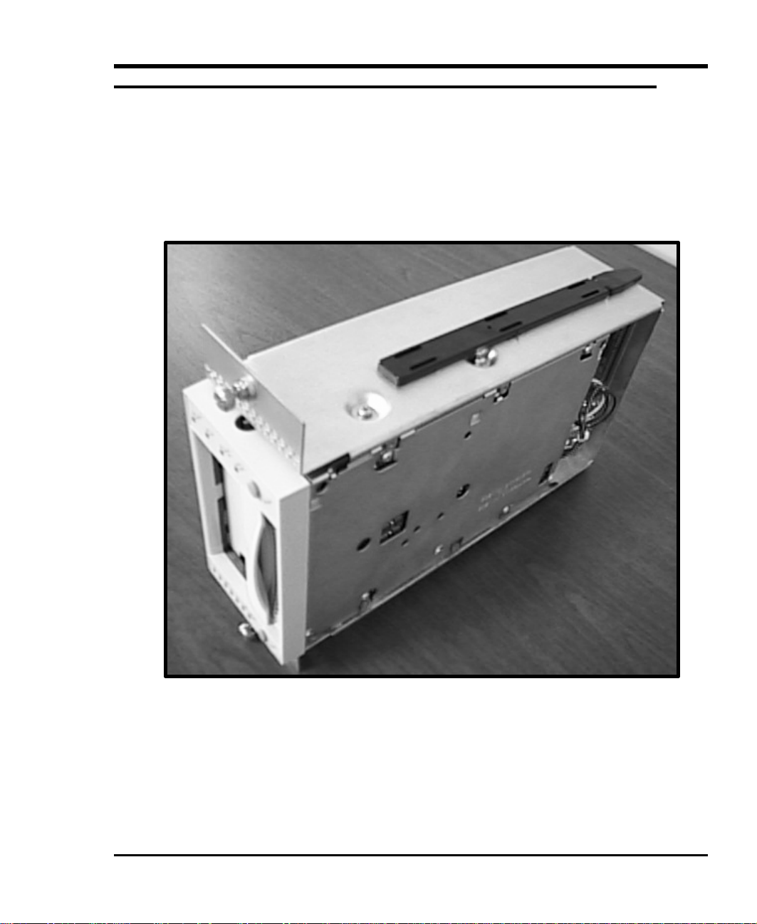
Equipment Description
The DLT tape drives employed in the Tape Array 5 Rackmount Enclosure are mounted in easily
inserted/removed drive carrier modules. The modules slide into the front of the Tape Array 5
enclosure and are retained with captive screws located at the top and bottom of the carrier. Each
module contains SCSI and power connectors, which dock with mating connectors inside the Tape
Array 5 enclosure. The modules provide all power and data connections between the drives and the
Tape Array 5 enclosure.
Figure 1-1: Drive/Carrier Assembly
1
Page 4

The Tape Array 5 enclosure features a snap on/off front bezel. The bezel can be easily snapped off
SCSI Connector
Power Connector
Front Bezel
for drive carrier module insertion/removal. Media cartridges loaded into the drives are accessible
when the bezel is snapped in place.
2
Figure 1-2: Tape Array 5 Enclosure, Front View
Page 5

Installing Tape Drives
1. Snap off the front bezel by pulling each side away from the enclosure. Set the bezel aside.
Figure 1-3: Tape Array 5 Enclosure, Front View, Bezel Removed
3
Page 6

2. Insert each drive carrier module into the unit by sliding the mounting rail on the drive/carrier
Drive/Carrier Assembly
module into the rail guide mounted in the enclosure. The drive carrier module should seat
fully into the enclosure (the mounting screw flanges on the top and bottom of the carrier will
contact the enclosure chassis). Check the carrier to insure proper docking connections.
4
Figure 1-4: Drive/Carrier Assembly Being Installed
Page 7

3. Fully tighten the captive screws at the top and bottom of each drive carrier module to secure it
Lower Captive Screw
in the Tape Array 5 enclosure.
Upper Captive Screw
Figure 1-5: Tightening Captive Screws
Caution
When inserting a drive carrier module, be sure that the orientation
of the module is correct. The SCSI data cable connector should be
nearest the top of the carrier.
5
Page 8

Blank Page
6
 Loading...