

Page 1
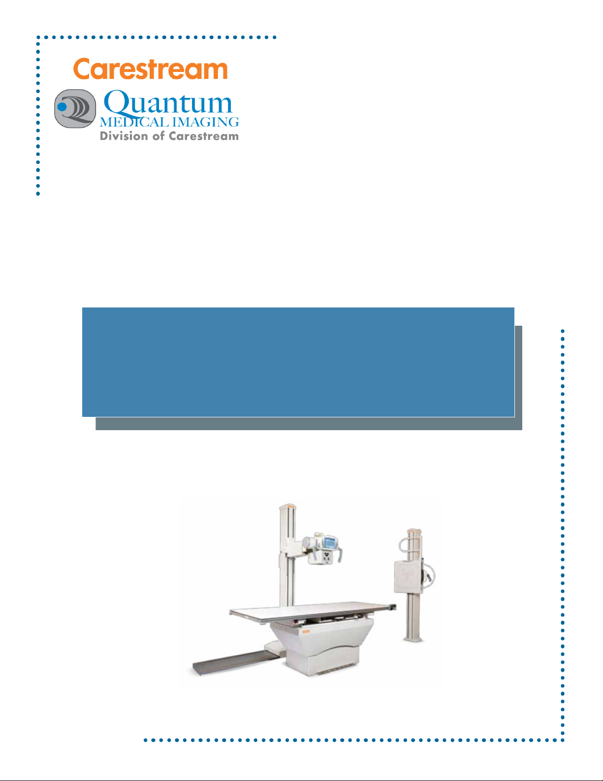
Q-Rad System
Operator’s Manual
Manual Part No. DC30-091 Revision F
Page 2

The original release of this manual dated 2011-02-24 (February 24, 2011) was drafted in the
English language by Quantum Medical Imaging, LLC.
This manual is copyrighted and all rights are reserved. No portion of this document may be copied, photocopied,
reproduced, translated, or reduced to any electronic medium or machine readable form without prior consent in
writing from Quantum Medical Imaging, LLC. (QMI)
Copyright © 2012 QMI
Quantum Medical Imaging, LLC
Division of Carestream
2002-B Orville Drive North
Ronkonkoma, NY 11779-7661 USA
Phone: (631) 567-5800
Fax: (631) 567-5074
E-mail: [email protected]
www.quantummedical.net
Made in U.S.A.
Page 3
Revision History
Revision Date Type Of Modification
A 2011-02-24 Initial Release
B 2011-11-02 Added DX-D DR configuration
C 2011-08-30 Added QG-DIG-DRX integration option
D 2012-01-30 Incorporated ECO 2568, 2609
E 2012-02-10 Renamed Operator Manual, changed EU Representative
F 2012-05-09 Updated per IEC 60601-1: 2005, IEC 60601-1-3,
IEC 60601-2-54
Page
Number Rev
i thru iv F
1-1 thru 1-14 F
2-1 thru 2-18 F
Page
Number Rev
Page
Number Rev
Q-Rad System - Operator’s Manual Revision F
Quantum Medical Imaging
i
Page 4

Revision History
REVISIO
N
A 2011-02-24--- Initial Release
B 2011-10-27All Various
DATE PAGES NOTES
THIS PAGE INTENTIONALLY LEFT BLANK
Revision F Q-Rad System - Operator’s Manual
ii Quantum Medical Imaging
Page 5

Table of Contents
Chapter 1: Safety Notices
General Safety Information . . . . . . . . . . . . . . . . . . . . . . . . . . . . . . . . . . .1-3
Warnings, Cautions, Notes . . . . . . . . . . . . . . . . . . . . . . . . . . . . . . . . . . . .1-3
Regulatory Compliance . . . . . . . . . . . . . . . . . . . . . . . . . . . . . . . . . . . . . .1-5
Classification . . . . . . . . . . . . . . . . . . . . . . . . . . . . . . . . . . . . . . . . . . .1-6
Compatibility . . . . . . . . . . . . . . . . . . . . . . . . . . . . . . . . . . . . . . . . . . .1-6
Intended Operator . . . . . . . . . . . . . . . . . . . . . . . . . . . . . . . . . . . . . . .1-7
Training. . . . . . . . . . . . . . . . . . . . . . . . . . . . . . . . . . . . . . . . . . . . . . .1-7
Applicable Standards. . . . . . . . . . . . . . . . . . . . . . . . . . . . . . . . . . . . . .1-7
Accompanying Documentation . . . . . . . . . . . . . . . . . . . . . . . . . . . . . . .1-7
Environmental Protection . . . . . . . . . . . . . . . . . . . . . . . . . . . . . . . . . . . . .1-8
Electromagnetic Compatibility
(EN 60601-1-2:2007/IEC 60601-1-2:2007) . . . . . . . . . . . . . . . . . . . . . .1-8
Abbreviation Definition. . . . . . . . . . . . . . . . . . . . . . . . . . . . . . . . . . . . . .1-13
Chapter 2: General Information
Instructions for Use . . . . . . . . . . . . . . . . . . . . . . . . . . . . . . . . . . . . . . . . .2-3
Overview . . . . . . . . . . . . . . . . . . . . . . . . . . . . . . . . . . . . . . . . . . . . . . . .2-4
Component Weights . . . . . . . . . . . . . . . . . . . . . . . . . . . . . . . . . . . . . .2-6
Generators (Cabinet) . . . . . . . . . . . . . . . . . . . . . . . . . . . . . . . . . . .2-6
Generators (Control Panel) . . . . . . . . . . . . . . . . . . . . . . . . . . . . . . .2-6
Tables . . . . . . . . . . . . . . . . . . . . . . . . . . . . . . . . . . . . . . . . . . . . .2-6
Tube Supports. . . . . . . . . . . . . . . . . . . . . . . . . . . . . . . . . . . . . . . .2-6
Upright Cassette Holders . . . . . . . . . . . . . . . . . . . . . . . . . . . . . . . .2-6
Heat Dissipation . . . . . . . . . . . . . . . . . . . . . . . . . . . . . . . . . . . . . . . . .2-7
Generators . . . . . . . . . . . . . . . . . . . . . . . . . . . . . . . . . . . . . . . . . .2-7
X-Ray Tube. . . . . . . . . . . . . . . . . . . . . . . . . . . . . . . . . . . . . . . . . .2-7
Tables . . . . . . . . . . . . . . . . . . . . . . . . . . . . . . . . . . . . . . . . . . . . .2-7
Tube Supports. . . . . . . . . . . . . . . . . . . . . . . . . . . . . . . . . . . . . . . .2-7
Upright Cassette Holders . . . . . . . . . . . . . . . . . . . . . . . . . . . . . . . .2-7
Q-Rad System - Operator’s Manual Revision F
Quantum Medical Imaging iii
Page 6

Table of Contents
System Operating Environment . . . . . . . . . . . . . . . . . . . . . . . . . . . . . .2-7
Transport and Non-Operating Environment. . . . . . . . . . . . . . . . . . . . . .2-7
System Configuration . . . . . . . . . . . . . . . . . . . . . . . . . . . . . . . . . . . . . . .2-8
Q-Rad Floor-Mounted System . . . . . . . . . . . . . . . . . . . . . . . . . . . . . . .2-8
Q-Rad “DRX Series” Integrated Radiography System . . . . . . . . . . . . . . .2-9
Intended Use . . . . . . . . . . . . . . . . . . . . . . . . . . . . . . . . . . . . . . . . . . . . 2-11
General Application Specification . . . . . . . . . . . . . . . . . . . . . . . . . . . . 2-11
Cleaning, Preventive Inspection and Maintenance . . . . . . . . . . . . . . . . . .2-11
Instructions for Disposal of Waste Equipment . . . . . . . . . . . . . . . . . . .2-11
Labeling . . . . . . . . . . . . . . . . . . . . . . . . . . . . . . . . . . . . . . . . . . . . . . . . 2-12
Power Disconnection . . . . . . . . . . . . . . . . . . . . . . . . . . . . . . . . . . . . . . . 2-17
Detachable Parts and Accessories . . . . . . . . . . . . . . . . . . . . . . . . . . . . . . 2-18
Revision F Q-Rad System - Operator’s Manual
iv Quantum Medical Imaging
Page 7

Chapter
C
HAPTER
1: S
AFETY
N
1
OTICES
1-1
Page 8

1-2
Page 9
Chapter 1 Safety Notices
General Safety Information
This product has been designed to meet stringent safety standards. All medical
electrical equipment requires proper installation, operation, and maintenance
(particularly with regard to safety).
It is vital that the user read, understand, note, and where applicable, strictly observe
all Warnings, Cautions, Notes and Safety markings within this document and on the
equipment, and that the user strictly follow all safety directions in this manual to help
ensure the safety of users and patients.
Every reasonable precaution has been taken during manufacture to safeguard the
health and safety of persons who will operate this equipment. The following
precautions must be observed at all times.
Warnings, Cautions, Notes
The following samples show how warnings, cautions, and notes appear in this
document. The text explains their intended use.
Indicates injury or death is possible if the instructions
Warning
Caution
Note
The purpose of safety icons, such as those shown below, is to indicate at a glance the
type of caution, warning or danger.
Warning Ionizing radiation: indicates the possibility of
Warning Dangerous voltage: indicates the presence of high
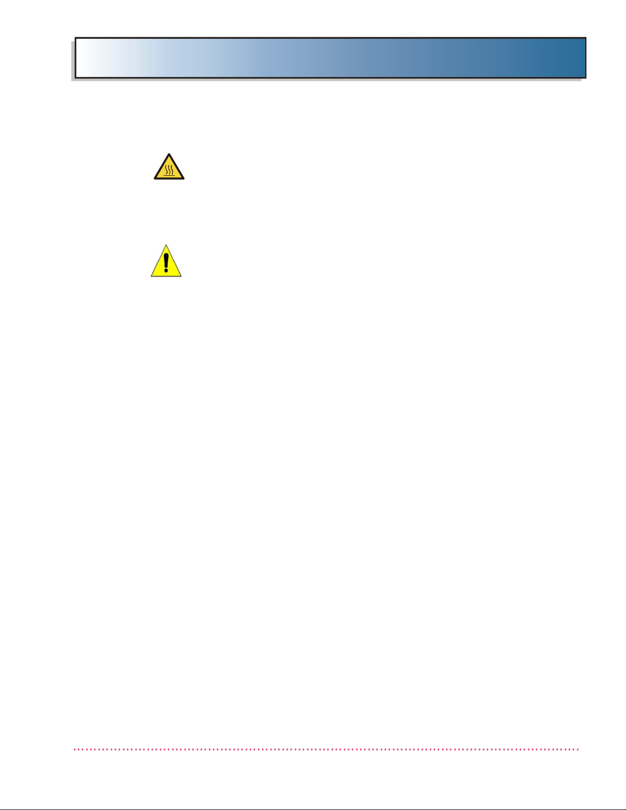
Warning Warning, hot surface.
are not obeyed. Instructs users to refer to
documentation if displayed without warning text.
Indicates that damage to equipment is possible if the
instructions are not obeyed.
Notes provide advice and highlight unusual points. A
note is not intended as an instruction.
increased levels of radiation.
voltage.
Q-Rad System - Operator’s Manual Revision F
Quantum Medical Imaging 1-3
Page 10
Chapter 1 Safety Notices
WARNING
Quantum Medical Imaging, LLC disclaims all responsibility from any injury
resulting from improper application of this equipment.
This equipment is sold to be used exclusively under the prescribed direction of a person who is licensed by law to operate equipment of this nature.
This equipment must be used in accordance with all safety procedures
described in this manual and must not be used for purposes other than
those described herein. In the United States, Federal law restricts this
device to sale, distribution, and use by or on order of a licensed physician.
Quantum Medical Imaging, LLC cannot assume responsibility for any malfunctioning of this equipment resulting from improper operation, maintenance, or repair, or from damage or modification of its components.
Failure to observe these warnings may cause serious injuries.
WARNING
X-rays are hazardous to both patient and operator unless established safe
exposure factors and operating instructions are observed.
Only qualified and authorized personnel shall operate this system. In this
context, qualified means those legally permitted to operate this equipment
in the jurisdiction in which the equipment is being used, and authorized
means those authorized by the authority controlling the use of the equipment. Full use must be made of all radiation protection features, devices,
systems, procedures and accessories.
It is important that everyone having anything to do with x-radiation be
properly trained and fully acquainted with the recommendations of the
National Council on Radiation Protection and Measurements as published
in NCRP Reports available from NCRP Publications, 7910 Woodmont Avenue, Suite 800, Bethesda, Maryland 20814-3095 (www.ncrp.com), and of
the International Commission on Radiological Protection (www.icrp.org),
and take adequate steps to protect against injury.
WARNING
X-ray equipment may cause injury if used improperly. The instructions contained in this manual must be read and followed when operating this unit.
Personal radiation monitoring and protective devices are available. You are
urged to use them to protect against unnecessary x-ray exposure.
Revision F Q-Rad System - Operator’s Manual
1-4 Quantum Medical Imaging
Page 11
Chapter 1 Safety Notices
WARNING
Exterior surfaces of the X-ray Tube can rise in temperature to levels where
the operator or patient could suffer burns. Avoid contact with the tube
housing.
WARNING
Changes, additions or maintenance to the equipment carried out by persons without appropriate qualifications and training and/or using unapproved spare parts may lead to serious risk of injury and damage to the
equipment as well as making the warranty void.
Regulatory Compliance
This certified Quantum Medical Imaging, LLC medical device has been designed,
manufactured, and calibrated to comply with governing Federal Regulations 21 CFR
Subchapter J and the performance standards attendant thereto. Upon installation, all
certified products require the filing of Form FD-2579 “Report of Assembly of a
Diagnostic X-ray System” by the assembler (i.e., the installer) with the appropriate
agencies; the “Installation Quality Assurance Checklist” must also be completed and
properly distributed upon installation. A copy of each form (pink copy) is provided to
the user. The installation report is completed by the installer and returned to
Quantum Medical Imaging, LLC.
Those responsible for the planning of x-ray equipment installations must be
thoroughly familiar and comply completely with NCRP Report No. 49, “Structural
Shielding Design and Evaluation for Medical Use of X-Rays and Gamma Rays of
Energies up to 10 MeV”, as revised or replaced in the future. Those authorized to
operate, test, participate in or supervise the operation of the equipment must be
thoroughly familiar and comply completely with the currently established safe
exposure factors and procedures described in publications such as Subchapter J of
Title 21 of the Code of Federal Regulations, “Diagnostic X-Ray Systems and Their
Major Components,” and NCRP Report No. 102, “Medical X-Ray, Electron Beam and
Gamma Ray Protection for Energies Up to 50 MeV—Equipment Design and Use” as
revised or replaced in the future.
This equipment must only be used in rooms that comply with all applicable laws or
regulations that have the force of law, concerning electrical safety for this type of
equipment.
Scheduled maintenance is essential to the assurance of continued integrity of this
equipment with respect to regulatory compliance. The continuance of certified
performance to the regulatory standard is incumbent upon the user's diligent
conformance to recommended maintenance instructions.
Q-Rad System - Operator’s Manual Revision F
Quantum Medical Imaging 1-5
Page 12
Chapter 1 Safety Notices
N
Complies with EC Directive 93/42/EEC for Medical Devices,
FDA Center for Devices and Radiological Health (CDRH) - Title 21 CFR Subchapter J
EU Authorized Representative:
Carestream Health France
1, rue Galilée
93192 NOISY-LE-GRAND CEDEX
France
Classification
This product has been classified as Class I, Type B. This equipment is not suitable
for use in the presence of a flammable anesthetic mixture with air or with oxygen
or with nitrous oxide. Protection against Harmful Ingress of Water (Ordinary),
enclosed equipment without protection against ingress of liquids.
MEDICAL ELECTRICAL EQUIPMENT
WITH RESPECT TO ELECTRIC SHOCK, FIRE,
MECHANICAL HAZARDS ONLY
IN ACCORDANCE WITH UL 60601-1-1 AND
CAN/CSA C22.2 NO. 601.1
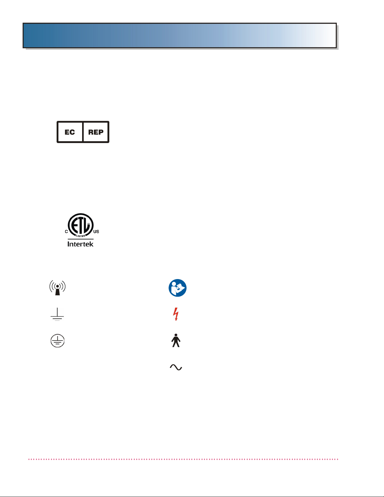
The following symbols may be used for marking on this equipment or equipment
documentation:
Non-ionizing Radiation Consult operating instructions
Earth (ground) Dangerous Voltage
Protective Earth (ground) Type B Equipment
Connection point for the
neutral conductor on
PERMANENTLY INSTALLED
EQUIPMENT
Alternating current
Revision F Q-Rad System - Operator’s Manual
1-6 Quantum Medical Imaging
Page 13

Chapter 1 Safety Notices
Compatibility
The equipment described in this manual must only be used in combination with
other equipment or components if these are expressly recognized by Quantum
Medical Imaging, LLC as compatible.
Intended Operator
This equipment is intended to be installed, used and operated only in accordance
with the safety procedures given within this manual for the purpose for which it
was designed. Before attempting to work with this equipment, read, understand,
note and strictly observe all warnings, cautions and safety markings on the
equipment.
Users include those persons who actually handle the equipment and those who
have authority over the equipment.
Training
Users of this equipment shall have received adequate training on its safe and
effective use before attempting to work with the equipment. Training
requirements may vary from country to country. The User shall make sure that
training is received in accordance with local laws or regulations that have the
force of law.
Applicable Standards
The Q-Rad Radiographic System complies with:
• IEC 60601-1: 2005
• IEC 60601-1-2: 2007
• IEC 60601-1-3: 2008
• IEC 60601-1-6:2010
• IEC 62366: 2007
Accompanying Documentation
The documentation consists of a System Operator’s manual (this document),
System Service manual (DC30-109) and related documentation, depending on
system configuration, as shown in Chapter 2, GENERAL INFORMATION, Table
2-1. The documentation shall be kept with the system for easy reference.
Q-Rad System - Operator’s Manual Revision F
Quantum Medical Imaging 1-7
Page 14

Chapter 1 Safety Notices
Environmental Protection
This equipment contains certain materials and chemical compounds incidental to the
manufacture of electrical and electronic equipment, and improper “end-of-life”
disposal of such equipment can result in environmental contamination. Therefore, this
equipment should not be disposed of as ordinary household waste, but should instead
be delivered to a designated electrical and electronic waste disposal or recycling
center. For further information on disposing of electrical and electronic waste, contact
the cognizant authority within the jurisdiction.
Electromagnetic Compatibility (EN 60601-1-2:2007/IEC 60601-1-2:2007)
The Q-Rad Radiographic System is intended for use in the electromagnetic
environment specified below. As such, Q-Rad Radiographic System must be installed
and put into service according to the information provided in the accompanying
Service Manual. Unauthorized changes to this product Do not make any modifications
Portable and mobile RF communications equipment can affect medical electrical
equipment. It is therefore recommended that the operation of equipment of this type
such as mobile telephones, cordless microphones and other similar mobile radio
equipment be restricted from the vicinity of this device.
Use of accessories, transducers and cables other than those specified in the
accompanying documents, may result in increased emissions or decreased immunity
of the equipment.
Guidance and manufacturer's declaration - electromagnetic emissions
The Q-Rad Radiographic System is intended for use in the electromagnetic environment specified below. The customer or the user of the Q-Rad Radiographic System should assure that it
is used in such an environment.
Emissions test Compliance Electromagnetic environment -
guidance
RF emissions
CISPR 11
Group 1 The Q-Rad Radiographic System
uses RF energy only for their internal
functions. Therefore, the RF emissions are very low and are not likely
to cause any interference in nearby
electronic equipment.
Revision F Q-Rad System - Operator’s Manual
1-8 Quantum Medical Imaging
Page 15

Chapter 1 Safety Notices
Guidance and manufacturer's declaration - electromagnetic emissions
RF emissions
CISPR 11
Harmonic emissions
IEC 61000-3-2
Voltage fluctuations/
flicker emissions
IEC 61000-3-3
Class A The Q-Rad Radiographic System is
suitable for use in all establishments
Class A
Complies
other than domestic and those
directly connected to the public lowvoltage power supply network that
supplies buildings used for domestic
purposes.
Guidance and manufacturer's declaration - electromagnetic immunity
The Q-Rad Radiographic System is intended for use in the electromagnetic environment specified below. The
customer or the user of the Q-Rad Radiographic System should assure that it is used in such an environment.
Immunity test IEC 60601
test level
Electrostatic
discharge (ESD)
IEC 61000-4-2
±6 kV contact
±8 kV air
Compliance
level
±6 kV contact
±8 kV air
Electromagnetic environment
- guidance
Floors should be wood, concrete or ceramic tile. If floors are
covered with synthetic material,
the relative humidity should be
at least 30 %.
Electrical fast
transient/burst
IEC 61000-4-4
Surge
IEC 61000-4-5
±2 kV for power supply
lines
±1 kV for input/output
lines
±1 kV differential mode
±2 kV common mode
±2 kV for power supply
lines
±1 kV for input/output
lines
±1 kV differential mode
±2 kV common mode
Mains power quality should be
that of a typical commercial or
hospital environment.
Mains power quality should be
that of a typical commercial or
hospital environment.
Q-Rad System - Operator’s Manual Revision F
Quantum Medical Imaging 1-9
Page 16

Chapter 1 Safety Notices
Guidance and manufacturer's declaration - electromagnetic immunity
Voltage dips,
short interruption,
and voltage
variations on power
supply
input lines
IEC 60601-4-11
Power frequency
(50/60 Hz)
IEC 61000-4-8
NOTE: U
is the A.C. mains voltage prior to application of the test level.
T
< 5 % U
T
(>95 % dip in UT)
for 0.5 cycle
< 5 % U
T
(>95 % dip in UT)
for 0.5 cycle
Mains power quality should be
that of a typical commercial or
hospital environment. If the user
of the Q-Rad Radiographic Sys-
40 % U
T
(60 % dip in UT)
for 5 cycles
70 % U
T
(30 % dip in UT)
< 5 % U
T
(> 95 % dip in UT)
for 5 s
40 % U
T
(60 % dip in UT)
for 5 cycles
70 % U
T
(30 % dip in UT)
< 5 % U
T
(> 95 % dip in UT)
for 5 s
tem requires continued operation during power mains
interruptions, it is recommended
that the Q-Rad Radiographic
System be powered from an
uninterruptible power supply or
battery.
3 A/m 3 A/m Power frequency magnetic
fields should be at levels characteristic of a typical location in
a typical commercial or hospital
environment
Guidance and manufacturer's declaration - electromagnetic immunity
The Q-Rad Radiographic System is intended for use in the electromagnetic environment specified
below. The customer or the user of the Q-Rad Radiographic System Q-Rad Radiographic System
should assure that it is used in such an environment.
Immunity test IEC 60601
test level
Compliance
level
Electromagnetic environment -
guidance
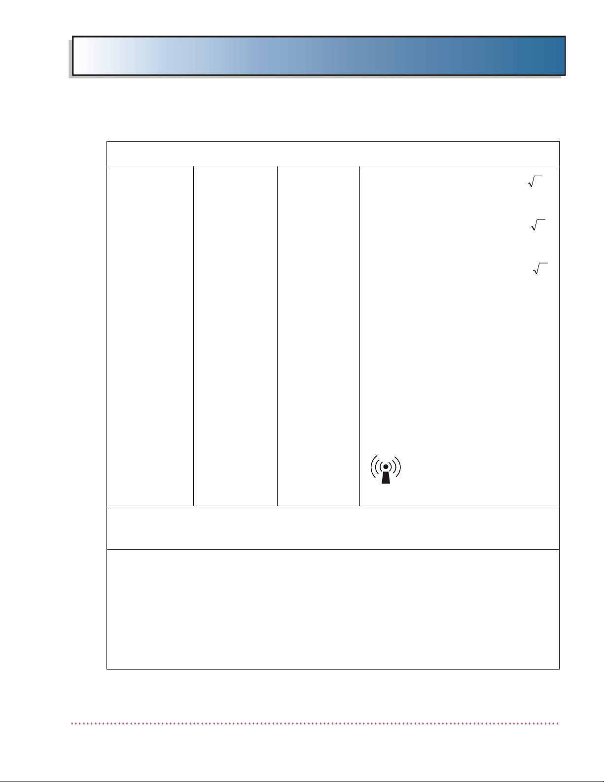
Portable and mobile RF communications
equipment should be used no closer to any
part of the Q-Rad Radiographic System,
including cables, than the recommended
separation distance calculated from the
equation applicable to the frequency of the
transmitter.
Recommended separation distance
Revision F Q-Rad System - Operator’s Manual
1-10 Quantum Medical Imaging
Page 17
Chapter 1 Safety Notices
Pd 2,1
Pd 2,1
Pd 3,2
Guidance and manufacturer's declaration - electromagnetic immunity
Conducted RF
IEC 61000-4-6
Radiated RF
IEC 61000-4-3
3 Vrms
150 kHz to 80
MHz
3 V/m
80 MHz to 2,5
GHz
3 Vrms
3 V/m
, 80 MHz to 800 MHz
, 800 MHz to 2,5 GHz
where P is the maximum output power rating of the transmitter in watts (W) according to the transmitter manufacturer and d
is the recommended separation distance in
metres (m).
Field strengths from fixed RF transmitters,
as determined by an electromagnetic site
a
survey
ance level in each frequency range.
Interference may occur in the vicinity of
equipment marked with the following symbol:
, should be less than the compli-
b
NOTE 1 At 80 MHz and 800 MHz, the higher frequency range applies.
NOTE 2 These guidelines may not apply in all situations. Electromagnetic propagation is affected by
absorption and reflection from structures, objects and people.
a
Field strengths from fixed transmitters, such as base stations for radio (cellular/cordless) telephones and land mobile radios, amateur radio, AM and FM radio broadcast and TV broadcast cannot
be predicted theoretically with accuracy. To assess the electromagnetic environment due to fixed RF
transmitters, an electromagnetic site survey should be considered. If the measured field strength in
the location in which the Q-Rad Radiographic System is used exceeds the applicable RF compliance
level above, the Q-Rad Radiographic System should be observed to verify normal operation. If abnormal performance is observed, additional measures may be necessary, such as re-orienting or relocating the Q-Rad Radiographic System.
b
Over the frequency range 150 kHz to 80 kHz, field strengths should be less than 3 V/m.
Q-Rad System - Operator’s Manual Revision F
Quantum Medical Imaging 1-11
Page 18
Chapter 1 Safety Notices
Pd 2,1
Pd 2,1
Pd 3,2
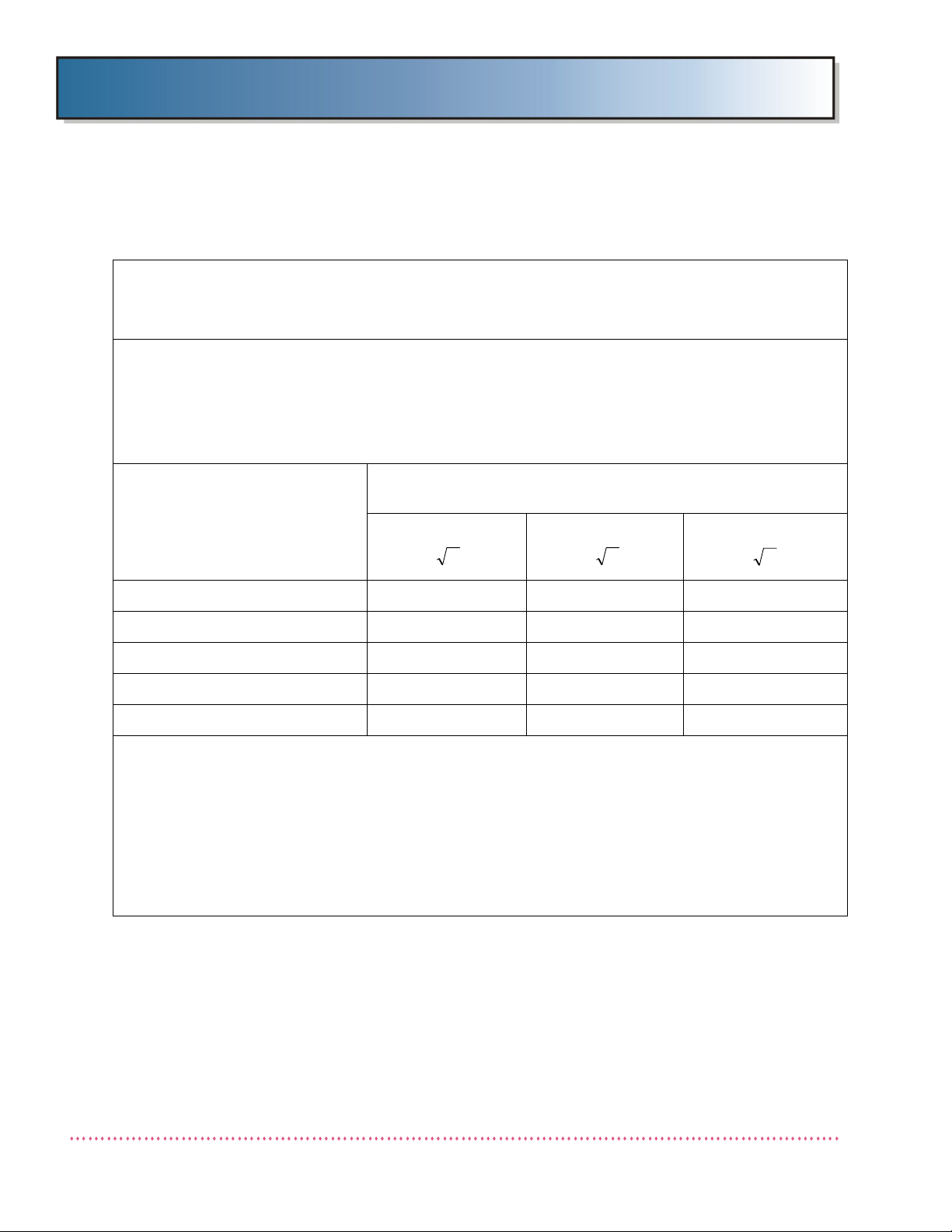
Recommended separation distances between
portable and mobile RF communications equipment and the
Q-Rad Radiographic System
The Q-Rad Radiographic System is intended for use in an electromagnetic environment in which radiated RF disturbances are controlled. The customer or the user of the Q-Rad Radiographic System QRad Radiographic System can help prevent electromagnetic interference by maintaining a minimum distance between portable and mobile RF communications equipment (transmitters) and the Q-Rad Radiographic System as recommended below, according to the maximum output power of the communications
equipment.
Rated maximum output power
of transmitter
W
0,01 0,12 0,12 0,23
0,1 0,38 0,38 0,73
1 1,2 1,2 2,3
10 3,8 3,8 7,3
100 12 12 23
For transmitters rated at a maximum output power not listed above, the recommended separation distance d in metres (m) can be estimated using the equation applicable to the frequency of the transmitter,
where P is the maximum output power rating of the transmitter in watts (W) according to the transmitter
manufacturer.
NOTE 1 At 80 MHz and 800 MHz, the separation distance for the higher frequency range applies.
NOTE 2 These guidelines may not apply in all situations. Electromagnetic propagation is affected by
absorption and reflection from structures, objects and people.
Separation distance according to frequency of transmitter
m
150 kHz to 80 MHz 80 MHz to 800 MHz 800 MHz to 2,5 GHz
Revision F Q-Rad System - Operator’s Manual
1-12 Quantum Medical Imaging
Page 19

Chapter 1 Safety Notices
Abbreviation Definition
The following abbreviations and acronyms may be found in this document. Their
definition is explained below.
AEC Automatic Exposure Control
Btu British Thermal Unit
CR Computed Radiography
dDistance
DR Digital Radiography
HF High Frequency
hPa Hecto-Pascal
hr Hour
kg Kilogram
kHz Kilohertz
KVA Kilovolt-Ampere
lb Pound
m Meter
MHz Megahertz
mm Millimeter
OCP Operator Control Panel
P Power (max.)
RF Radio Frequency
VVolt
WWatt
WEEE Waste Electrical and Electronic Equipment
Q-Rad System - Operator’s Manual Revision F
Quantum Medical Imaging 1-13
Page 20

Chapter 1 Safety Notices
THIS PAGE INTENTIONALLY LEFT BLANK
Revision F Q-Rad System - Operator’s Manual
1-14 Quantum Medical Imaging
Page 21

Chapter
C
HAPTER
2: G
ENERAL
I
NFORMATION
2
2-1
Page 22

2-2
Page 23
Chapter 2 General Information
Instructions for Use
The instructions for using Quantum’s Q-Rad Radiographic System, including an explanation of the function
of controls, displays and signals, and the sequence of operation, are contained in each of the system
component user’s manual indicated in Tabl e 2- 1.
WARNING: This equipment must be operated with reasonable care.
Manufacturer’s equipment recommendations described in this manual mus t
be observed.
WARNING: Use a focal spot-to-film distance as large as possible in order to
keep the absorbed dose to the patient as low as reasonably achievable.
WARNING: During each exposure, the individual operating the X-ray
machine must exit the radiographic operatory and stand behind a leaded
wall.
Q-Rad System - Operator’s Manual Revision F
Quantum Medical Imaging 2-3
Page 24
Chapter 2 General Information
Overview
This chapter describes the configurations of the Q-Rad Radiographic System, which typically includes
Quantum Medical Imaging HF Series X-ray Generators, radiographic tables, free-standing tube support,
upright cassette holder, collimator, X-ray tube, ion chamber (when equipped with AEC option), and image
receptor.
Detailed instructions for successful integration of the compatible Quantum components are published in
the Service Manuals for each of the various system components.
Table 2-1. Q-Rad System Components User/Service Documents
Component Type Model(s) User Manual P/N Service Manual
P/N
X-ray Generator,
Single-phase, nonStored Energy
X-ray Generator,
Single-phase, Stored
Energy
X-ray Generator,
Three-phase
TechVision Supplementary Generator
Control Panel
Radiographic Table,
Elevating Tabletop
Radiographic Table,
Non-Elevating Tabletop
QG-25, QG-25-5,
QG-32, QG-32-5,
QG-40, and QG-40-5
QG-20-SE, QG-32-SE,
QG-40-SE, QG-50-SE
QG-32-2, QG-32-3,
QG-40-2, QG-40-3,
QG-50, QG-50-2,
QG-65, and QG-80
QG-TV-Q, QG-TV-IP-Q,
QG-TV-F, QG-TV-IP-F, QGTV-C, QG-TV-IP-C
QT-750 DC30-006 DC30-007
QT-740 DC30-006 DC30-007
Odyssey - DC30-010
Quest - DC30-015
Q-Vision - DC30-101
Odyssey - DC30-010
Quest - DC30-015
Q-Vision - DC30-101
Odyssey - DC30-010
Quest - DC30-015
Q-Vision - DC30-101
DC30-048 (Quantum
non-integrated systems,
DC30-120 (Q-Vision
non-integrated systems)
DC30-126 (Carestream
integrated systems)
Q-Vision/Odyssey DC30-011
Quest - DC30-063
Q-Vision/Odyssey DC30-011
Quest - DC30-063
Q-Vision/Odyssey DC30-011
Quest - DC30-063
DC30-049
Radiographic Table,
Non-Elevating Tabletop
Tube Support, Floor/
Wall Mounted
Tube Support, FreeStanding (Floor)
Mounted
QT-730 DC30-003 DC30-003
QS-500 DC30-034 DC30-005
QS-550 DC30-034 DC30-009
Revision F Q-Rad System - Operator’s Manual
2-4 Quantum Medical Imaging
Page 25

Chapter 2 General Information
Table 2-1. Q-Rad System Components User/Service Documents
Component Type Model(s) User Manual P/N Service Manual
P/N
Radiographic Upright
Cassette Holder,
Collimator, Manual Progeny, MC150
Collimator, Automatic Progeny, Linear II
Collimator, Programmable
X-ray tube Toshiba E7239X, E7242X,
DX-D 500
Digital DRX Series
Integration Software
(QG-DIG-DRX)
(Optional)
n
Q-Rad
QW-420, QW-420-S, QW420-D, QW-400
Huestis, 150MC
Ralco R108
Progeny, Linear IV
Huestis, CM-32211-QMI CM-21-002 CM-21-002
E7252X, E7254X, E7869X
Varian RAD-14, RAD-60,
RAD-92
Dunlee DA 1092, DA 1036
QG-DIG-DRX DC30-123 DC30-123
DC30-039 DC30-040
00-02-1078
CM-21-001
MTR108
00-02-1559
00-02-1517
Refer to data sheet provided with tube
00-02-1078
CM-21-001
MTR108
00-02-1559
00-02-1517
Refer to data sheet
provided with tube
Dose Area Product
(DAP) meter
(Optional)
Vacutec VacuDAP OEM DAP-std-fl-
tw_BA011.3.doc
DAP-std-fltw_BA011.3.doc
Q-Rad System - Operator’s Manual Revision F
Quantum Medical Imaging 2-5
Page 26

Chapter 2 General Information
Component Weights
Generators (Cabinet)
Single-Phase,
non-Stored Energy (SE) units: 135.2 kg (298.0 lb)
32, 40, and 50 kW,
SE units: 195.5 kg (431.0 lb)
Three-Phase units: 172.4 kg (380.0 lb)
Generators (Control Panel)
Odyssey (without pedestal): 2.3 kg (5.0 lb)
Odyssey (with pedestal): 11.3 kg (25.0 lb)
Quest (without pedestal): 1.8 kg (4.0 lb)
Quest (with pedestal): 10.9 kg (24.0 lb)
Q-Vision: 5.9 kg (13.0 lb)
TechVision Option: 4.3 kg (9.5 lb)
without internal High Speed Starter (HSS)
176.0 kg (388.0 lb)
with internal High Speed Starter (HSS)
Tables
Model QT-730: 79.4 kg (175.0 lb)
Model QT-740: 158.8 kg (350.0 lb)
Model QT-750: 226.8 kg (500.0 lb)
Tube Supports
Model QS-550: 272.2 kg (600.0 lb)
Model QS-500: 230.4 kg (508.0 lb)
Upright Cassette Holders
Model QW-420: 102.1 kg (225.0 lb)
Model QW-420-S: 102.1 kg (225.0 lb)
Model QW-420-D: 90.7 kg (200.0 lb)
Model QW-400: 45.4 kg (100.0 lb)
Revision F Q-Rad System - Operator’s Manual
2-6 Quantum Medical Imaging
Page 27

Heat Dissipation
Generators
Cabinet Typical Heat Output: 3600 BTU per hour
Control Panel Typical Heat Output: 130 BTU per hour
X-Ray Tube
Max. Heat Output (600 khu tube): 2000 BTU per hour
Tables
QT-730 Typical Heat Output: 40 BTU per hour (from receptor)
QT-750 Typical Heat Output: 400 BTU per hour
QT-740 Typical Heat Output: 100 BTU per hour
Tube Supports
QS-500/QS-550: 200 BTU per hour
Upright Cassette Holders
Typical Heat Output: 50 BTU per hour
Chapter 2 General Information
NOTE: The above calculations are typical, based upon average usage. Air
circulation around the electronic cabinets must be provided. This
includes the sides, back, front, and top of cabinet.
System Operating Environment
Ambient Temperature: 10–40 °C (50–104 °F)
Relative Humidity: 15–75 %
Atmospheric Pressure: 700–1060 hPa
Transport and Non-Operating Environment
Ambient Temperature: -25 to +55 °C (-13 to 131 °F)
Relative Humidity: 5–95 %
Atmospheric Pressure: 500–1060 hPa
Q-Rad System - Operator’s Manual Revision F
Quantum Medical Imaging 2-7
Page 28
Chapter 2 General Information
System Configuration
The Quantum Q-Rad System consists of a combination of integrated radiographic components, typically
including an X-ray generator, X-ray tube and tube support, collimator, radiographic table, and an upright
cassette holder. Different types of image receptors may be utilized with the Q-Rad System, including
computed radiography (CR) receptors, as well as conventional analog film cassettes.
Q-Rad Floor-Mounted System
The Q-Rad Floor-Mounted system is configured around either a free-standing,
floor-mounted tube support (Model QS-550) or a wall/ceiling mounted tube support (Model QS-500).
Because the free-standing version does not require wall attachment for support, it provides enhanced
freedom of movement in the patient vicinity for the operator.
Recumbent examinations are accomplished utilizing an elevating (Model QT-750) or the
non-elevating (Model QT-740 and QT-730) radiologic tables. Standing (weight-bearing) examinations
are performed using an upright, non-tilting (Model QW-420 Series) chest stand (cassette holder).
The X-ray generator is available in various power output and operator control panel types, with the
typical configuration including a 80 kW output generator with an Odyssey operator control.
Table 2-2. Q-Rad Floor Mounted System
COMPONENT COMPONENT
COMPONENT MODEL#
DESIGNATION
GENERATOR QG1 SINGLE-PHASE: QG-25-1, QG-32-1, QG-40-1
STORED ENERGY
QG-40-SE, QG-50-SE
THREE-PHASE
QG-40-3, QG-50-3, QG-65-3, QG-80-3
GENERATOR
CONTROL PANEL
SUPPLEMENTAL
GENERATOR
CONTROL PANEL
(TECHVISION)
TABLE QT1 QT-730, QT-740, QT-750
TUBE SUPPORT QS1 QS-500, QS-550
WALL STAND QW1 QW-420, QW-420-D, QW-420-S, QW-400
OCP1 QUEST SERIES
QG-400, QG-500
ODYSSEY SERIES
QG-5000, QG-6500, QG-8000
Q-VISION SERIES
QGV-65, QGV-80
OCP2 QG-TV-IP-F
: QG-20-SE, QG-32-SE,
: QG-32-2, QG-32-3, QG-40-2,
: QG-200, QG-250, QG-320,
: QG-3200, QG-4000,
: QGV-32, QGV-40, QGV-50,
X-RAY TUBE TU1 TOSHIBA
E7869X
VARI A N
DUNLEE
: E7239X, E7242X, E7252X, E7254X,
: RAD-14, RAD-60, RAD-92
: DA 1092, DA 1036
Revision F Q-Rad System - Operator’s Manual
2-8 Quantum Medical Imaging
Page 29
Chapter 2 General Information
Table 2-2. Q-Rad Floor Mounted System
COMPONENT COMPONENT
COMPONENT MODEL#
DESIGNATION
COLLIMATOR QC1 PROGENY
LINEAR II, LINEAR IV
RALCO
HUESTIS
DAP QD1 VacuDAP-OEM DISPLAY + ION CHAMBER,
VacuDAP ION CHAMBER
ION CHAMBER IN1 AID
IMAGE
RECEPTOR
RC1 GRID CABINET
: ICX 1153
BUCKY CABINET
KLB10-08013
: MC150, MC150 PINNACLE,
: R 108/464 DHHS
: 150MC (MANUAL), CM 32211-QM1
: R50-17GC
: PROGENY KLB10-08011,
Q-Rad “DRX Series” Integrated Radiography System
The Q-Rad DRX Series Integrated Digital Radiography (DR) System combines the Q-Rad System’s HF
Series X-ray Generator and Carestream DRX-1 Digital Imaging Systems by way of a common user
interface (QG-DIG-DRX Software) running on the Carestream DRX-1 Digital Imaging System’s
Workstation computer.
When QG-DIG-DRX Software is implemented, all user interaction (except PREP and EXPOSE) with the
HF Series X-ray Generator is accomplished via the Digital Imaging System’s touchscreen computer,
thereby eliminating the need for a separate generator Operator Control Panel.
The Q-Rad DRX Series Integrated System consists of either a fixed DR Detector, and/or a Portable DR
Detector, and a Workstation Computer. The DR System is connected to the Quantum X-Ray Generator
by way of a software interface module.
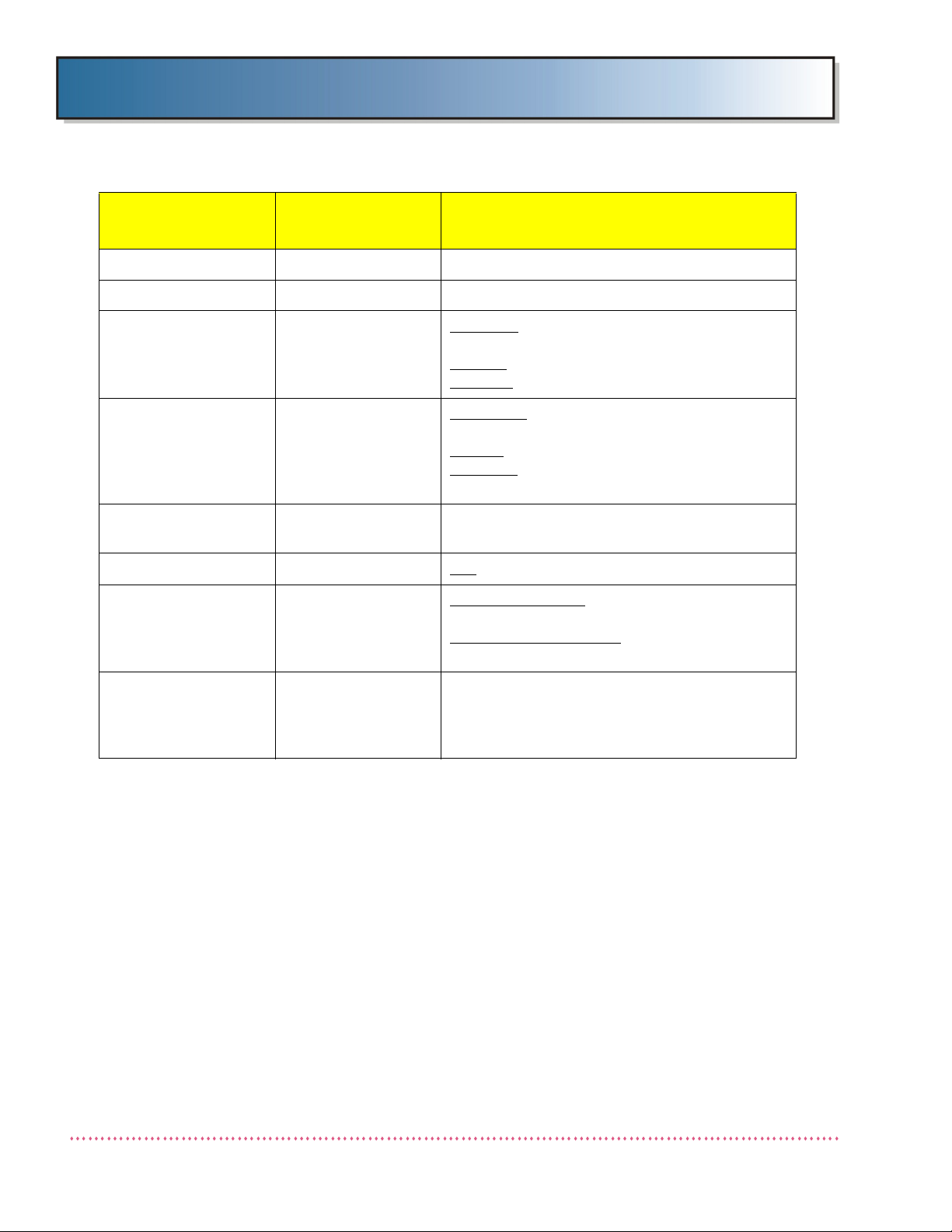
Table 2-3. Q-Rad System, DRX Series Integration
COMPONENT COMPONENT
DESIGNATION
GENERATOR QG1 SINGLE-PHASE
STORED ENERGY
QG-40-SE, QG-50-SE
THREE-PHASE
QG-40-3, QG-50-3, QG-65-3, QG-80-3
GENERATOR CONTROL PANEL
SUPPLEMENTAL
GENERATOR CONTROL PANEL (TECHVISION)
TABLE QT1 QT-730, QT-740, QT-750
OCP1 Q-CONNECT (WITH DRX-1 WORKSTATION)
QG-DIG-DRX
OCP2 QG-TV-IP-C, QG-TV-IP-F
COMPONENT MODEL#
: QG-32-1, QG-40-1
: QG-32-SE,
: QG-32-2, QG-32-3, QG-40-2,
:
Q-Rad System - Operator’s Manual Revision F
Quantum Medical Imaging 2-9
Page 30
Chapter 2 General Information
Table 2-3. Q-Rad System, DRX Series Integration
COMPONENT COMPONENT
DESIGNATION
TUBE SUPPORT QS1 FLOOR-MOUNTED: QS-500, QS-550
WALL STAND QW1 QW-420, QW-420-D, QW-420-S
X-RAY TUBE TU1 TOSHIBA
E7869X
VARIAN
DUNLEE
COLLIMATOR QC1 PROGENY
LINEAR II, LINEAR IV
RALCO
HUESTIS
(PROGRAMMABLE)
DAP QD1 VacuDAP-OEM DISPLAY + ION CHAMBER,
VacuDAP ION CHAMBER
ION CHAMBER IN1 AID
IMAGE
DETECTOR CABINET
RC1 FIXED DETECTOR
: ICX 1153
Q-FDR-T (TABLE)
PORTABLE DETECTOR
STAND), Q-DRT-T (TABLE)
COMPONENT MODEL#
: E7239X, E7242X, E7252X, E7254X,
: RAD-14, RAD-60, RAD-92
: DA 1092, DA 1036
: MC150, MC150 PINNACLE,
: R 108/464 DHHS
: 150MC (MANUAL), CM-32211-QMI
: Q-FDR (WALL STAND),
: Q-DRT (WALL
DR IMAGING DETECTOR/SYSTEM
QR1, QR2 CARESTREAM DRX-1 IMAGING SYSTEM
(PORTABLE, WIRELESS)
CARESTREAM DRX-1 IMAGING SYSTEM
(FIXED, 4343R)
Revision F Q-Rad System - Operator’s Manual
2-10 Quantum Medical Imaging
Page 31
Chapter 2 General Information
Intended Use
The Quantum Q-Rad System provides diagnostic quality images to aid the physician with diagnosis. The
system can be used to perform radiographic exposures of the skeleton (including skull, spinal column, and
extremities), chest, abdomen, and other body parts. The Q-Rad Radiographic System is not indicated for
use in mammography.
General Application Specification
Patient Population:
Age: Newborn to geriatric
Weight: Up to 294.8 kg (650.0 lb)
Region of Body: Produces images of any bone in the human body,
including the hand, wrist, arm, foot, ankle, knee, leg, or
spine.
Operator Requirements:
Education/Training: This equipment is sold to be used exclusively under the
prescribed direction of a person who is licensed by law
to operate equipment of this nature.
Application:
Location: Professional use only, indoor use only.
Physical Environment: Refer to Q-Rad System operating and non-operating
specifications in this chapter.
Frequency of Use: Intermittent operation, limited primarily by loading
characteristics specific to tube type used in the system.
Mobility: Stationary
Cleaning, Preventive Inspection and Maintenance
Instructions for cleaning, preventive inspection and routine maintenance of Q-Rad Radiographic System,
are included in each of the system component user’s and service manuals indicated in Table 2- 1 .
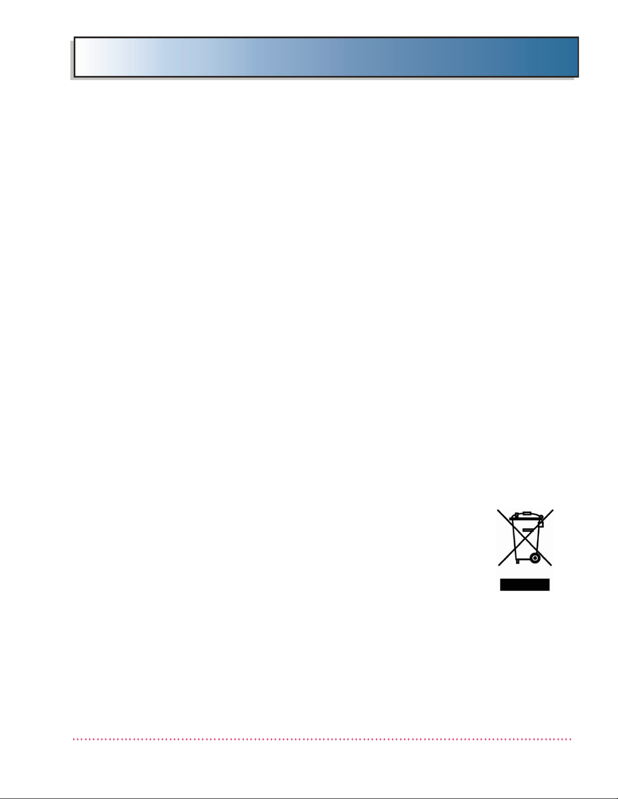
Instructions for Disposal of Waste Equipment
In the European Union, this symbol indicates that when the last user wishes to
discard this product, it must be sent to appropriate facilities for recovery and
recycling. Contact your local representative for additional information on the
collection and recovery programs available for this product.
Q-Rad System - Operator’s Manual Revision F
Quantum Medical Imaging 2-11
Page 32
Chapter 2 General Information
REGULATORY
LABEL
CONFIGURATION
LABEL
GENERATOR CABINET
GENERATOR
COMPLIANCE
LABEL
Labeling
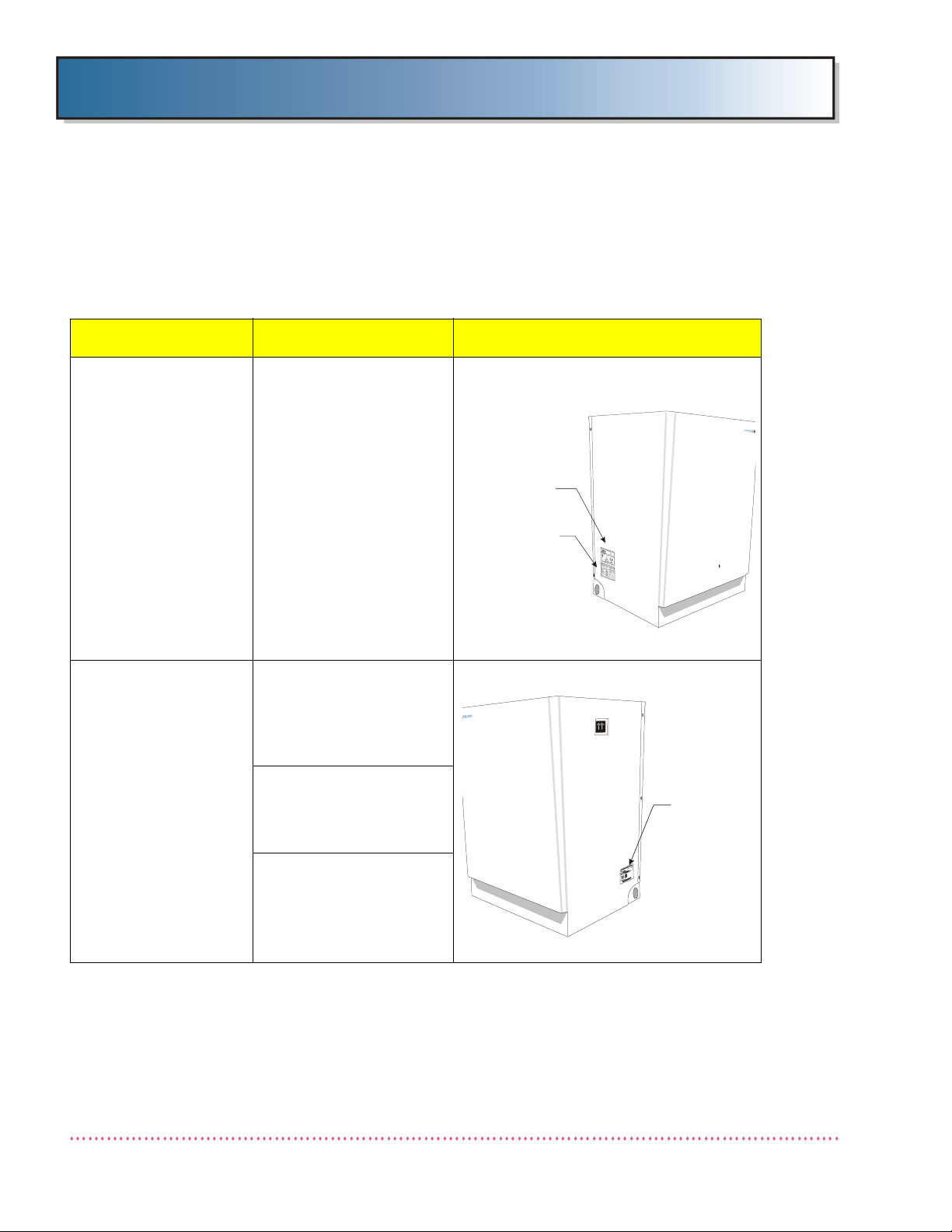
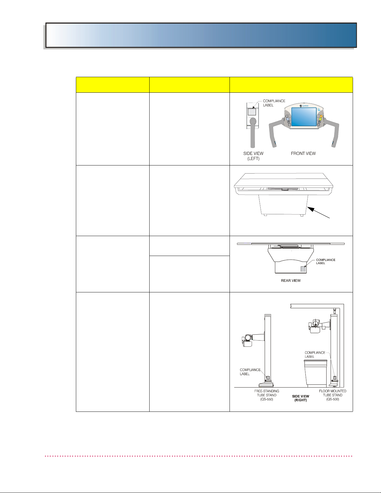
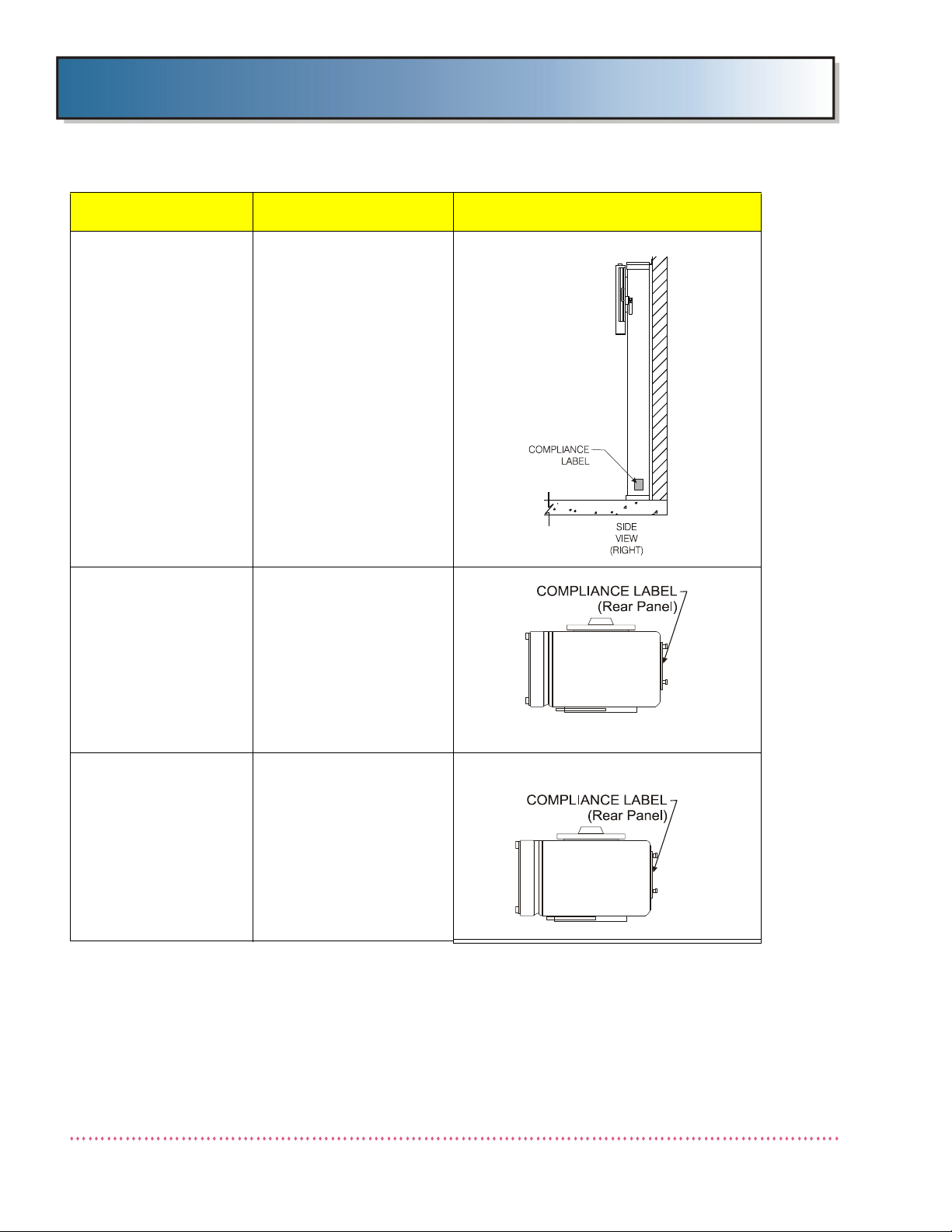
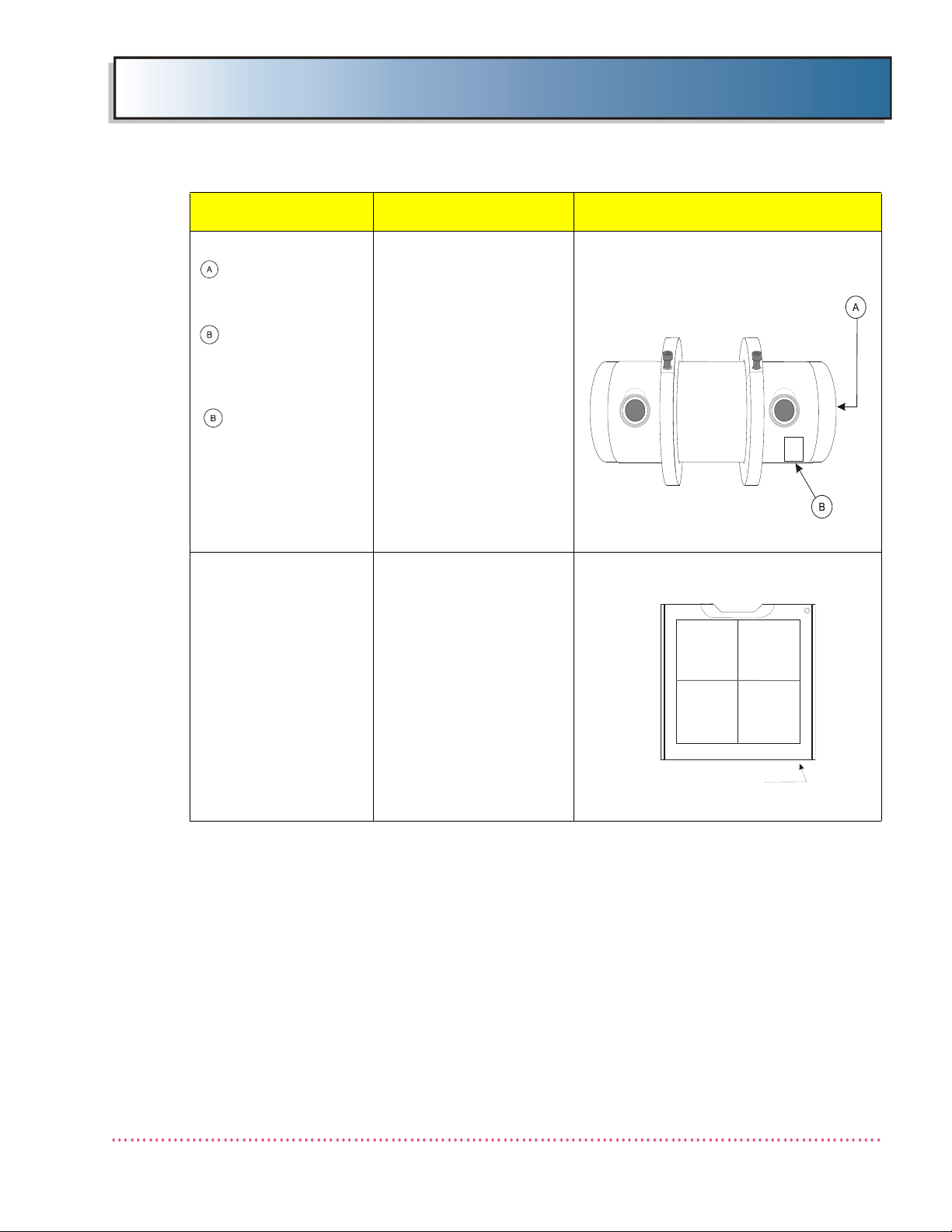
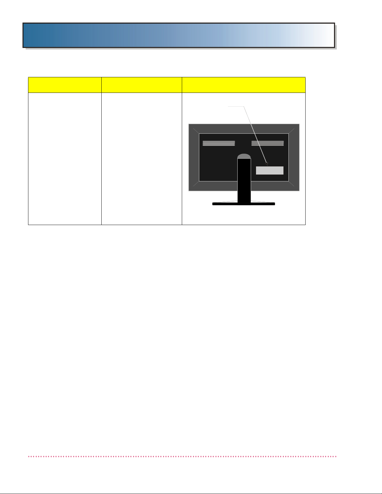
Each component of the Q-Rad System has its own rating plate/serial label. The following table provides the
general location of the rating plate/serial label on each of the various types of components that could be
incorporated in a Q-Rad System.
Table 2-4. Q-Rad System Components Labeling Guide
Component Type Model(s) Label Location
Q-Rad System Q-Rad
X-ray Generator Single-phase,
non-Stored Energy
QG-25, QG-25-5,
QG-32, QG-32-5,
QG-40, and QG-40-5
Single-phase, Stored
Energy
QG-20-SE, QG-32-SE,
QG-40-SE, QG-50-SE
Three-phase
QG-32-2, QG-32-3,
QG-40-2, QG-40-3,
QG-50, QG-50-2,
QG-65, and QG-80
Revision F Q-Rad System - Operator’s Manual
2-12 Quantum Medical Imaging
Page 33
Chapter 2 General Information
compliance label
Table 2-4. Q-Rad System Components Labeling Guide
Component Type Model(s) Label Location
TechVision
Supplementary Gener-
ator Control Panel
Radiographic Table Fixed Non-Float Tabletop
Radiographic Table Non-Elevating Tabletop
QG-TV-F,
QG-TV-IP-F,
QG-TV-C,
QG-TV-IP-C
QT-730
QT-740
Elevating Tabletop
QT-750
Tube Support,
Floor Mounted
QS-500
QS-550
Q-Rad System - Operator’s Manual Revision F
Quantum Medical Imaging 2-13
Page 34
Chapter 2 General Information
Table 2-4. Q-Rad System Components Labeling Guide
Component Type Model(s) Label Location
Radiographic Upright
Cassette Holder
Collimator, Manual PROGENY MC-150
QW-420,
QW-420-S, QW-420-D
QW-400
HUESTIS 150MC
RALCO R108/484 DHHS
Collimator, Automatic PROGENY Linear II,
Linear IV
HUESTIS CM-32211-QM1
Revision F Q-Rad System - Operator’s Manual
2-14 Quantum Medical Imaging
Page 35
Chapter 2 General Information
X-RAY TUBE
COMPLIANCE LABEL
LOCATIONS
REAR VIEW
COMPLIANCE
LABEL/DATAPLATE
CABINET (FRONT)
Table 2-4. Q-Rad System Components Labeling Guide
Component Type Model(s) Label Location
X-ray tube
VARI A N:
RAD-14, RAD-60,
RAD-92
TOSHIBA:
DUNLEE:
Digital Image Detector
Cabinet
E7239X, E7242X,
E7252X, E7254X,
E7869X
DA 1092, DA 1036
Q-DRT
Q-DRT-T
Q-FDR
Q-FDR-T
Q-Rad System - Operator’s Manual Revision F
Quantum Medical Imaging 2-15
Page 36
Chapter 2 General Information
REAR VIEW
COMPLIANCE
LABEL
Table 2-4. Q-Rad System Components Labeling Guide
Component Type Model(s) Label Location
Integration Option Q-Rad DRX Series
(QG-DIG-DRX)
Revision F Q-Rad System - Operator’s Manual
2-16 Quantum Medical Imaging
Page 37
Chapter 2 General Information
Power Disconnection
Refer to the following table for Q-Rad System component power disconnection methods.
Table 2-5. DX-D 500
n
Q-Rad System Component Power Disconnection Method
Component Type Model Means of Power
Disconnect
X-ray Generator,
Single-phase, nonStored Energy
X-ray Generator,
Single-phase, Stored
Energy
X-ray Generator, Threephase
TechVision Supplementary Generator Control
Panel
Radiographic Table,
Non-Elevating Tabletop
Radiographic Table,
Non-Elevating Tabletop
QG-25, QG-25-5,
QG-32, QG-32-5,
QG-40, and QG-40-5
QG-20-SE, QG-32-SE,
QG-40-SE, QG-50-SE
QG-32-2, QG-32-3,
QG-40-2, QG-40-3,
QG-50, QG-50-2,
QG-65, and QG-80
QG-TV-Q, QG-TV-IP-Q,
QG-TV-F, QG-TV-IP-F,
QG-TV-C, QG-TV-IP-C
QT-730 ON/OFF circuit breaker
QT-740 Unplug Line Cord
ON/OFF circuit breaker
CB1 on generator cabinet
ON/OFF circuit breaker
CB1 on generator cabinet
ON/OFF circuit breaker
CB1 on generator cabinet
ON/OFF circuit breaker
CB1 on generator cabinet
CB1 on generator cabinet
Radiographic Table,
Elevating Tabletop
Tube Support, Floor/Wall
Mounted
Tube Support, FreeStanding (Floor)
Mounted
QT-750 Unplug Line Cord
QS-500 ON/OFF circuit breaker
CB1 on generator cabinet
QS-550 ON/OFF circuit breaker
CB1 on generator cabinet
Q-Rad System - Operator’s Manual Revision F
Quantum Medical Imaging 2-17
Page 38

Chapter 2 General Information
Table 2-5. DX-D 500
n
Q-Rad System Component Power Disconnection Method
Component Type Model Means of Power
Disconnect
Radiographic Upright
Cassette Holder, NonTilting
Collimator, Manual Progeny, MC150
Collimator, Automatic Progeny, Linear II
X-ray tube Toshiba E7239X, E7242X,
Dose Area Product
Meter (optional)
QW-420, QW-420-S,
QW-420-D, QW-400
Huestis, 150MC
Ralco, R108
Progeny, Linear IV
Huestis Programmable,
CM-32211-QMI
E7252X, E7254X, E7869X
Varian RAD-14, RAD-60,
RAD-92
Dunlee DA 1092, DA1036
Vacutec Display Unit:
VacuDAP OEM (QD1-2)
Vacutec Ion Chamber: VacuDAP OEM (QD1-1)
ON/OFF circuit breaker
CB1 on generator cabinet
ON/OFF circuit breaker
CB1 on generator cabinet
Unplug Line Cord (ACS
Power Supply & Junction
Box)
ON/OFF circuit breaker
CB1 on generator cabinet
Unplug Line Cord
Carestream Digital
Imaging System
DRX-1 Quick Reference Card for
the Carestream DRX-1
System, document 8G8318
Carestream DRX-1 System
Safety and Regulatory
Information with Hardware
User’s Guide, document
7H8166
Carestream DRX-1 System
Battery Charger User’s
Guide, document 8H6193
Detachable Parts and Accessories
Instructions for detachable parts and accessories of Q-Rad Radiographic System are included in each of
the system component user’s manual indicated in Tab le 2 -1 .
<End of Document>
Revision F Q-Rad System - Operator’s Manual
2-18 Quantum Medical Imaging
 Loading...