

Page 1

quantum
MASCHINEN - GERMANY
© 2007
GB
Page 118 / 01 / 2008 Version 1.2.5 B 13 / B14 / B16 / B20 / B25 / B32 Drilling machine
Bench drill
B 13
B 14
B 16
B 20 / B20 Vario
Operating manual
Version 1.2.5
Keep for future reference !
Pillar drill
B 25 / B 25 Vario
B 32 / B 32 Vario
Illustr. 0-1: B13 B 25
Page 2

quantum
MASCHINEN - GERMANY
© 2007
GB
Page 2 Drilling machine B 13 / B14 / B16 / B20 / B25 / B32 Version 1.2.5 18 / 01 / 2008
Table of contents
1Safety
1.1 Safety warnings (warning notes) .................................................................................. 5
1.1.1 Classification of hazards ......................................... ... ... .... ... ... ...................... 5
1.1.2 Further ideograms ......................................................................................... 6
1.2 Proper use ....................................... ... .... ... ... ... .... ...................................... ... .... ... ... ...... 6
1.3 Possible dangers caused by the drilling machine .........................................................7
1.4 Qualification of employees ........................................................................................... 8
1.4.1 Target group ..................................................................................................8
1.4.2 Authorized persons .............................................. ......................................... 8
1.5 User’s position ........................................ ... ... ... .......................................... ... .... ............9
1.6 Safety devices ..............................................................................................................9
1.6.1 ON / OFF switch ..........................................................................................10
1.6.2 Drilling machine table .................................................................................. 10
1.7 Separating protective devices .................................................................................... 10
1.7.1 Drill chuck protection ................................................................................... 10
1.7.2 Protective cover of the pulleys .................................................................... 11
1.7.3 Prohibition, warning and mandatory labels .................................................11
1.8 Safety check ...............................................................................................................11
1.9 Personal protective equipment ................................................................................... 11
1.10 Safety during operation .............................................................................................. 12
1.11 Safety during maintenance ......................................................................................... 12
1.12 Use of lifting equipment ..............................................................................................13
1.12.1 Mechanical maintenance work .................................................................... 13
1.13 Accident report .......................... ... ... .......................................... ... .... ... ... ... ... ..............13
1.14 Electric ................................ ................................................. .......................................13
2 Technical Data
2.1 Power connection ....................................................................................................... 14
2.2 Drilling capacity ..................... .... ... ... ... .... ... .......................................... ... ... .................14
2.3 Spindle holding fixture ................................................................................................14
2.4 Drilling machine table ............ .... ... ... ... .......................................... .... ... ... ... ... .... ..........14
2.10 Emissions ................................................................................................................... 15
2.5 Dimensions ................................... .................................................... ..........................15
2.6 Working area ................................................... .... ... ... .......................................... ... ... . 15
2.7 Revolutions ................................ ................................................ .................................15
2.8 Environmental conditions ...........................................................................................15
2.9 Operating material ...................................................................................................... 15
3 Assembly
3.1 Extent of supply .......................................................................................................... 16
3.2 Transport .................................................................................................................... 16
3.3 Storage ...................................... .................................................................................17
3.4 Installation and assemby ............................................................................................17
3.4.1 Assembly .................................... ............................. ............................. ....... 17
3.4.2 Installation ................................................................................................... 20
3.4.3 Installation drawings ... ... ... ... .... ... ... ... .... ......................................... .... ... .......20
3.5 First use ........................... ... ... .... ... ... ... .... .......................................... ..........................21
3.5.1 Phase inverter for 400V - machines ............................................................22
Page 3

quantum
MASCHINEN - GERMANY
© 2007
GB
Page 318 / 01 / 2008 Version 1.2.5 B 13 / B14 / B16 / B20 / B25 / B32 Drilling machine
4Handling
4.1 Safety ......................................................................................................................... 23
4.2 Control and indicating elements ................................................................................. 23
4.2.1 B 13, B 14 ................................................................................................... 23
4.2.2 B 16, B 20, B 25, B 32, B20 Vario, B25 Vario, B32 Vario ........................... 24
4.2.3 Drill depth stop ............................................................................................ 24
4.2.4 Inclination of the drilling machine table ....................................................... 25
4.3 Speed alternation ....................................................................................................... 26
4.3.1 Speed table ................................................................................................. 27
4.4 Standard values for speeds with HSS – Eco – twist drill ............................................ 31
4.5 Drill chuck ................................................................................................................... 32
4.5.1 Gear rim-drill chuck ......................................................... ... .... ... ... ... ... .... ... .. 32
4.5.2 Disassembly of the drill chuck ..................................................................... 32
4.6 Cooling ....................................................................................................................... 32
4.7 Before starting the working process ........................................................................... 32
4.8 During the working process ........................................................................................ 33
5 Maintenance
5.1 Safety ......................................................................................................................... 35
5.1.1 Preparation ................................................................................................. 35
5.1.2 Restarting ........................................... ................................ ......................... 35
5.2 Inspection and maintenance ...................................................................................... 35
5.3 Repair ................................ ............................................. ............................................ 37
6 Ersatzteile - Spare parts B13, B14, B16, B20, B25, B32
6.1 Ersatzteilzeichnung - Parts drawing B13 / B14 .......................................................... 38
6.2 Bohrfutterschutz B13, B14 - Drill chuck protection B13, B14 ..................................... 39
6.2.1 Ersatzteilliste - Parts list B13 / B14 ............................................................. 39
6.3 Ersatzteilzeichnung - Parts drawing B 16 ....................... ... ... .... ... ... ............................ 41
6.4 Bohrfutterschutz B16 - Drill chuck protection B16 ...................................................... 42
6.4.1 Ersatzteilliste - Parts list B16 ....................................................................... 42
6.5 Ersatzteilzeichnung - Parts drawing B20 / B25 (Vario) .............................................. 44
6.6 Bohrfutterschutz B20, B25 - Drill chuck protection B20, B25 ..................................... 45
6.6.1 Ersatzteilliste - Parts list B20 / B25 (Vario) ................................................. 45
6.7 Ersatzteilzeichnung - Parts drawing B32 (Vario) ........................................................ 48
6.8 Bohrfutterschutz B32 - Drill chuck protection B32 ...................................................... 49
6.8.1 Ersatzteilliste - Parts list B32 (Vario) ........................................................... 49
6.9 Schaltplan - Wiring diagram B13-B20 (230V) ............................................................ 52
6.10 Schaltplan - Wiring diagram B20-B32 (400V) ............................................................ 52
6.11 Schaltplan - Wiring diagram B20Vario-B32Vario (230V) ............................................ 53
7 Malfunctions
8 Appendix
8.1 Copyright .............................. ............................................................................. .........56
8.2 Terminology/Glossary ................................................................................................ 56
8.3 Warranty ............................ ............................................. ............................................ 57
8.4 Disposal ................................ ................ ................ ................ ................. ................ ..... 57
8.5 RoHS , 2002/95/CE .................................................................................................... 57
8.6 Product follow-up ..................... ... .... ... ... ... .... ... ... ... .......................................... ... .... ... .. 58
8.7 EC - declaration of conformity .................................................................................... 59
Page 4

Safety
quantum
MASCHINEN - GERMANY
© 2007
GB
Page 4 Drilling machine B 13 / B14 / B16 / B20 / B25 / B32 Version 1.2.5 18 / 01 / 2008
1 Safety
Glossary of symbols
This part of the operating manual
• does explain the meaning and how to use the war ning refe re n ce s c ontained in this ope ra tin g
manual,
• does explain how to use the drilling machine,
• highlights the dangers that might arise for you and others if these instructions are not followed thoroughly,
• informs you on how to prevent dangers.
In addition to this operating manual, please note
• applicable laws and regulations,
• legal regulations for preventing an accident,
• the prohibition, warning and mandatory signs as well as the warning notes on the drilling
machine.
European standards must be kept during installation, operation, maintenance and repair of the
drilling machine.
If European standards are not applied at the national legislation of the country of destination, the
specific applicable regulations of each country are to be observed.
If necessary, the required measures must be taken to comply with the specific regulations of
each country before the drilling machine is used for the first time.
Always keep the operating manual close to the drilling machine for further reference.
INFORMATION
If you are not able to solve a problem using this manual, please do not hesitate to contact us for
further professional advice:
Optimum Maschinen Germany GmbH
Dr. Robert-Pfleger-Str. 26
D- 96103 Hallstadt
info@optimum-maschinen.de
gives further advice
calls on you to get in action
• enumeration
notice
Page 5

quantum
MASCHINEN - GERMANY
Safety
© 2007
GB
Page 518 / 01 / 2008 Version 1.2.5 B 13 / B14 / B16 / B20 / B25 / B32 Drilling machine
1.1 Safety warnings (warning notes)
1.1.1 Classification of hazards
We classify the safety warnings into various levels. The table below gives an overview of the
classification of symbols (ideogram) and warning signs for each specific danger and its (possible) consequences.
ideogram warning alert definition / consequence
DANGER!
Threatening danger that will cause serious injury or
death to people.
WARNING!
Risk: A danger that might cause serious injury or death
to a person.
CAUTION!
Danger or unsafe procedure that might cause injury to
people or damage to property.
ATTENTION!
Situation that could cause damage to the machine and
to the product and other types of damages.
No risk of injury to people.
INFORMATION
Application advice and other important or useful information and notes.
No dangerous or harmful consequences for people or
objects.
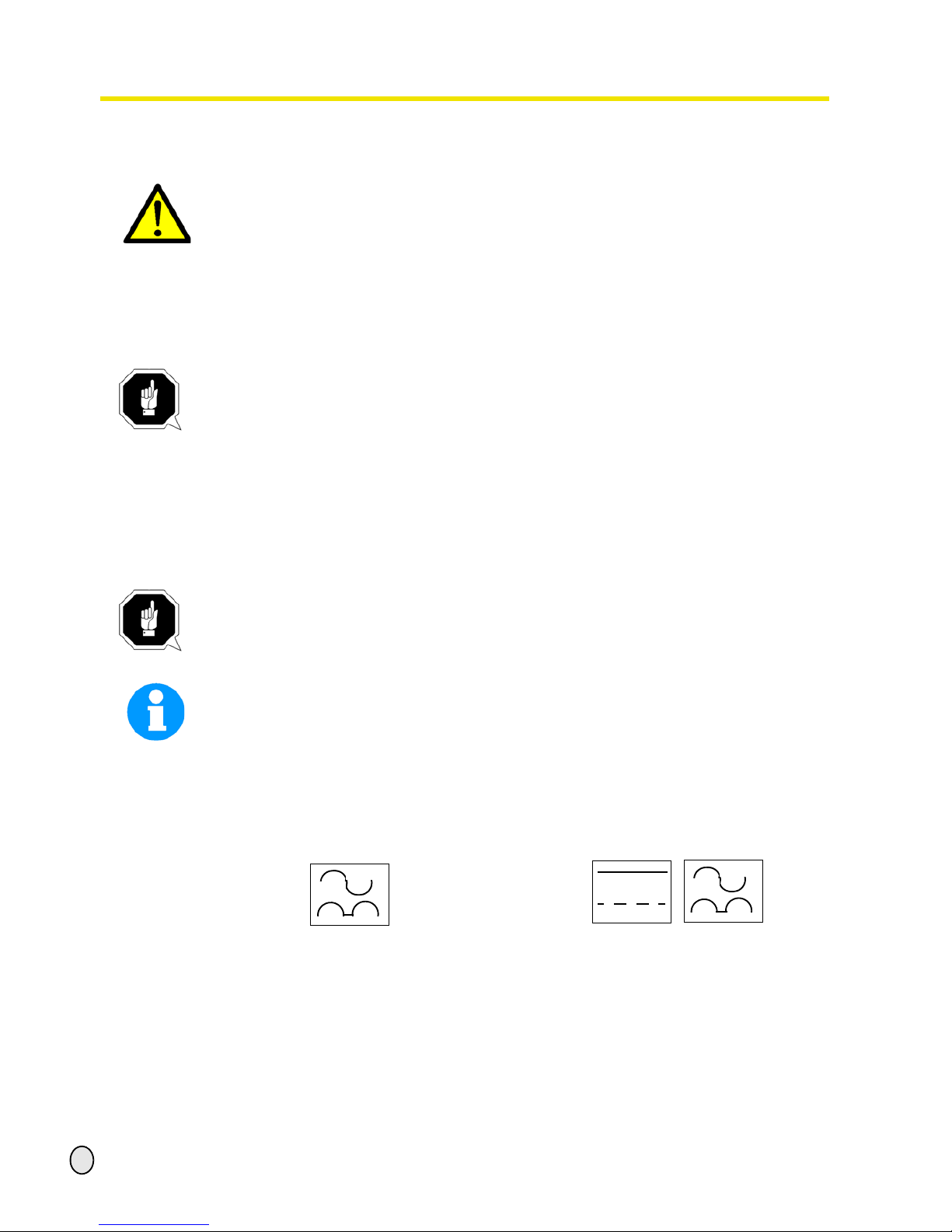
In case of certain dangers, we replace the ideogram by
or
general danger
with a warning ofinjuries to
hands,
hazardous
electrical voltage,
rotating parts.
Page 6

Safety
quantum
MASCHINEN - GERMANY
© 2007
GB
Page 6 Drilling machine B 13 / B14 / B16 / B20 / B25 / B32 Version 1.2.5 18 / 01 / 2008
1.1.2 Further ideograms
1.2 Proper use
WARNING!
In the event of improper use, the drilling-milling machine
• will endanger personnel,
• will endanger the machine and other material property of the operator,
may affect proper operation of the drilling machine.
The drilling machine is constructed and designed for the use in non-explosive surrounding. The
drilling machine is designed and manufactured to be used for drilling cold metals or other nonflammable materials or materials that do not constitute a health hazard by using a rotating cutting tool with various chucking grooves.
If the drilling machine is used in any way other than as described above, modified without the
authorisation of Optimum Maschinen GmbH or operated with different process data, then it is
being used improperly.
We do not take liability for damage caused by improper use.
We would like to stress that any modifications to the construction, or technical or technological
modifications that have not been authorised by Optimum Maschinen GmbH will also render the
guarantee null and void.
It is also part of proper use that
• the maximum values for the drilling machine are complied with,
• the operating manual is observed,
• inspection and maintenance instructions are observed.
„Technical Data“ on page 14
Warning of auto-
matic start-up!
Activation forbid-
den!
Pull the main plug! Use safety
glasses!
Use ear protec-
tion!
Use protective
gloves!
Use protective
boots!
Wear a safety suit! Protect the envi-
ronment!
Contact address
Page 7

quantum
MASCHINEN - GERMANY
Safety
© 2007
GB
Page 718 / 01 / 2008 Version 1.2.5 B 13 / B14 / B16 / B20 / B25 / B32 Drilling machine
WARNING!
Very serious injury.
It is forbidden to make any modifications or alternations to the operating values of the
drilling machine! They could endanger employees and cause damage to the drilling
machine.
1.3 Possible dangers caused by the drilling machine
The drilling machine is state of the art.
Nevertheless, there is a residual risk as the drilling machine operates with
• high revolutions,
• rotating parts,
• electrical voltage and currents.
We have used construction resources an d safety techniques to minimize the health risk to per-
sons resulting from these hazards.
If the drilling machine is used and maintained by employees who are poorly qualified, then there
might be a risk resulting from incorrect operation and unsuitable maintenance of the drilling
machine.
INFORMATION
Everyone involved in the assembly, commissioning, operation and maintenance must
• be duly qualified,
• strictly follow this operating manual.
Due to improper use
• there is a risk for the employee,
• the machine and further property might be endangered,
• the function of the drilling machine could be affected.
Always disconnect the drilling machine if cleaning or maintenance work is being carried out.
WARNING!
The drilling machine may only be used with the safety devices activated.
Disconnect the drilling machine immediately whenever you detect a failure in the safety
devices or when they are not mounted!
All additional installations carried out by the operator must incorporate the safety
devices prescribed.
This is your responsibility being the operator!
„Safety devices“ on page 9
Page 8

Safety
quantum
MASCHINEN - GERMANY
© 2007
GB
Page 8 Drilling machine B 13 / B14 / B16 / B20 / B25 / B32 Version 1.2.5 18 / 01 / 2008
1.4 Qualification of employees
1.4.1 Target group
This manual applies to
• the operators,
• the users,
• the maintenance staff.
Therefore, the warning notes refer to both operation and maintenance of the drilling machine.
Determine clearly and make a permanent decision in who will be responsible for the different
activities on the machine (operation, ma in te na nc e an d re pair).
Vague and unclear assignment of responsibilities constitute a safety hazard!
Always disconnect the main plug of the drilling machine. This will prevent it from being used by
unauthorized persons.
1.4.2 Authorized persons
WARNING!
Incorrect use and maintenance of the drilling machine constitute a danger for the staff,
objects and the environment .
Only authorized persons may operate the drilling machine!
Persons authorized to operate and maintain should be trained technical staff and
instructed by the ones who are working for the operator and for the manufacturer.
The operator must
Obligations
of the opera-
tor
• train the staff,
• instruct the staff in regular intervals (at least once a year) on
- all safety standards that apply to the drilling machine,
- the operation,
- accredited technical guidelines,
• check the knowledge of the staff,
• document training / instructions,
• require the staff to confirm participation in training / instructions by means of a signature,
• check if the staff is aware of safety rules and dangers in the workplace so that they observe
the operating manual.
The user must
Obligations
of the user
• have followed a training on the operation of the drilling machine,
• know the function and performance,
• before commissioning
- have read and understood the operating manual,
- be familiar with all safety devices and regulations.
Further
require-
ments to the
qualification
For working on the following machine parts, additional requirements are being applied:
• Electrical parts or operating agents: shall only be performed by an electrician or under the
guidance and supervision of an electrician.
Before starting work on electrical parts or operating agents, following measures are to be performed in the following order.
Page 9

quantum
MASCHINEN - GERMANY
Safety
© 2007
GB
Page 918 / 01 / 2008 Version 1.2.5 B 13 / B14 / B16 / B20 / B25 / B32 Drilling machine
disconnect all poles
secure against switching on
check dead circuit
1.5 User’s position
The user must stand in front of the drilling machine.
INFORMATION
The main switch of the drilling machine must be easily accessible.
1.6 Safety devices
Operate the drilling machine only with properly functioning safety devices.
Stop the drilling machine immediately if there is a failure in the safety device or if it is not func-
tioning for some reason.
It is your responsibility!
If the safety device has been activated or has failed, the drilling machine must only be operated
again when
• the cause of the failure has been removed,
• you have made sure that there is no existing danger for persons or objects.
WARNING!
If you bypass, remove or override a safety device in any other way, you are endangering
yourself and other persons working on the drilling machine. The possible consequences
are the following
• injuries due to components or parts of components flying off at high speed,
• contact with rotating parts,
• fatal electrocution.
The drilling machine includes the following safety devices:
• an EMERGENCY-STOP button,
• a drilling machine table with grooves to fasten the workpiece or a vice,
• a fixed screwed-on protective cover for the pulleys with micro switch,
• a drill chuck guard with micro switch.
Page 10

Safety
quantum
MASCHINEN - GERMANY
© 2007
GB
Page 10 Drilling machine B 13 / B14 / B16 / B20 / B25 / B32 Version 1.2.5 18 / 01 / 2008
1.6.1 ON / OFF switch
The lockable switch is equipped with an
EMERGENCY-STOP function and a
release for undervoltage.
Illustr.1-1: On / OFF switch
Open the cap of the switch in order to switch the drilling machine on.
CAUTION!
Even if the EMERGENCY-STOP button is activated the spindle will keep turning for sev-
eral seconds - depending on the pre-selected number of revolutions.
1.6.2 Drilling machine table
On the drilling machine table there are
holding fittings for sliding blocks.
WARNING!
There is danger of injury because of the
parts flying off. Tighten the workpiece
properly into the drilling machine table.
Illustr. 1-2: drilling machine table
1.7 Separating protective devices
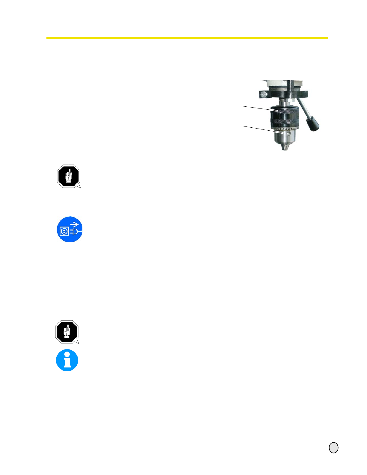
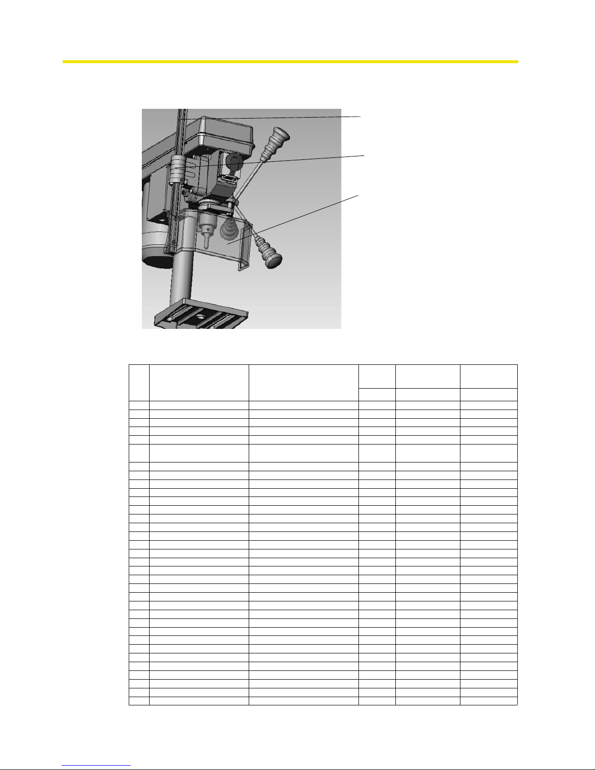
1.7.1 Drill chuck protection
Adjust the protective equipment to the correct height before you start working.
To do so, detach the clamping screw,
adjust the required height and retighten the
clamping screw.
A switch is integrated in the fixture of the
spindle protection which monitors that the
cover is closed.
INFORMATION
YOU CANNOT START THE MACHINE IF
THE DRILL CHUCK PROTECTION IS
NOT CLOSED.
Illustr.1-3: Drill chuck protection
ON / OFF switch
holding fixtures for
grooves
(14 mm)
Drill chuck protection
Page 11

quantum
MASCHINEN - GERMANY
Safety
© 2007
GB
Page 1118 / 01 / 2008 Version 1.2.5 B 13 / B14 / B16 / B20 / B25 / B32 Drilling machine
1.7.2 Protective cover of the pulleys
A protective cover for the belt pulleys is
mounted on the drilling head. A switch is
integrated in the protective cover which
monitors that the cover is closed.
INFORMATION
YOU CANNOT START THE MACHINE IF
THE PROTECTIVE COVER IS NOT
CLOSED.
Illustr.1-4: protective cover
1.7.3 Prohibition, warning and mandatory labels
INFORMATION
All warning labels must be legible. Check them regularly.
1.8 Safety check
Check the drilling machine at least once per shift. Inform the person responsible immediately of
any defect or change in the operating function.
Check all safety devices
• at the beginning of each shift (with the machine stopped),
• once a week (with the machine in operation),
• after every maintenance and repair work.
Check that the prohibition, warning and information labels as well as the markings on the drilling
machine
• are legible (clean them, if necessary),
• are complete.
1.9 Personal protective equipment
For certain work, personal protective equipment is required, such as:
• safety helmet,
• protective glasses or face guard,
• protective gloves,
• safety shoes with steel caps,
• ear protection.
Before starting work, make sure that the prescribed personal protective equipment is available
at the workplace.
CAUTION!
Dirty or eventually contaminated personal protective equipment might cause disease.
Clean your personal protective equipment
• after each use,
• regularly once a week.
protective cover
Page 12

Safety
quantum
MASCHINEN - GERMANY
© 2007
GB
Page 12 Drilling machine B 13 / B14 / B16 / B20 / B25 / B32 Version 1.2.5 18 / 01 / 2008
Personal protective equipment for special work
Protect your face and your eyes: Wear a safety helmet with a face guard for every work, especially for the kind of work where your face and eyes are exposed to hazards.
Use protective gloves when lifting or handling pieces with sharp edges.
Wear safety shoes when fitting, dismanteling or transporting heavy components.
1.10 Safety during operation
In the description of work with and on the drilling machine we highlight the dangers specific to
that work.
WARNING!
Before activating the drilling mac h ine, double check that this will
• not endanger other people,
• not cause damage to equipment.
Avoid unsafe working practice:
• Make sure that your work does not endanger anyone.
• The instructions of this manual must be observed strictly during assemby, operation, maintenance and repair.
• Do not work on the drilling machine, if your concentration is reduced, for example, because
you are taking medication.
• Observe the regulations for the prevention of accidents issued by your association for the
prevention of accidents and safety in the workplace or other inspection authorities.
• Inform the inspector of any danger or failure.
• Stay at the drilling machine until all rotating parts have come to a halt.
• Use the prescribed personal protective equipment. Make sure to wear a well-fitting work suit
and a hainet, if necessary.
• Do not use protective gloves when drilling.
1.11 Safety during maintenance
Inform the operating staff on time of any repair and maintenance work.
Report all safety-relevant changes or performance details of the drilling machine.Document all
changes, have the operating manual changed accordingly and train the machine operators.
Switching-off and securing the drilling machine
Unplug the main switch before starting any maintenance or repair work.
All machine components and hazardous voltages are d isc onnect ed.O nly the pos ition s which are
marked with the pictogram in the margin are excluded. Attach a warning sign on the machine.
Page 13

quantum
MASCHINEN - GERMANY
Safety
© 2007
GB
Page 1318 / 01 / 2008 Version 1.2.5 B 13 / B14 / B16 / B20 / B25 / B32 Drilling machine
1.12 Use of lifting equipment
WARNING!
Use of unstable lifting and load-suspension gear that might break under load can cause
very serious injuries or even death.
Check the lifting and load-suspension gear on
• sufficient load capacity,
• perfect condition.
Observe the regulations for the prevention of accidents issued by your association for
the prevention of occupational accidents and safety in the workplace or other inspection
authorities.
Fasten the loads properly. Do not walk under lifted loads !
1.12.1 Mechanical maintenance work
Remove all protection and safety de vices before starting maintenance wor k and re-install them
once the work has been completed, such as:
• covers,
• safety indications and warning signs,
• earth (ground) cables.
If you remove protection or safety devices, refit them immediately after completing the work.
Check if they are working properly!
1.13 Accident report
Inform your superiors and Optimum Maschinen GmbH immediately in case of accidents, possible sources of danger and any action which almost lead to an accident "near misses".
"Near misses" may have many possible causes.
The sooner they are notified, the faster theses causes can be eliminated.
1.14 Electric
Have the machine and / or the electrical equipment checked regularly, at least every six months.
Eliminate immediately all defects such as loose connections, defective wires, etc.
A second person must be present during work on live components, to disconnect the power in
case of an emergency.
Disconnect the drilling machine immediately if there is a malfunction in the power supply!
„Maintenance“ on page 34
Page 14

Technical Data
quantum
MASCHINEN - GERMANY
© 2007
GB
Page 14 Drilling machine B 13 / B14 / B16 / B20 / B25 / B32 Version 1.2.5 18 / 01 / 2008
2 Technical Data
The following data which give dimensions and weight are the manufacturer’s authorized
machine data.
2.1 Power connection
B 13 B 14 B 16 B 20
B 20 Vario
B 25
B 25 Vario
B 32
B 32 Vario
power connection~50Hz
230 V
300 W
230 V
350W
230 V
450 W
3 x 400 V
550 W
3 x 400 V
550 W
3 x 400 V
1,1 kW
or
230 V
550 W
230V
550 W
230V
1,1 kW
2.2 Drilling capacity
B 13 B 14 B 16 B 20 B 25 B 32
drilling capacity in steel
[mm]
13 14 16 20 20 32
reach [mm] 104 104 125 170 170 225
spindle sleve travel [mm] 50 50 65 80 80 125
2.3 Spindle holding fixture
B 13 B 14 B 16 B 20 B 25 B 32
spindle holding fixture firm/B16 firm/B16 MK2 MK2 MK3 MK4
2.4 Drilling machine table
B 13 B 14 B 16 B 20 B 25 B 32
slewable on the spindle
axis [mm]
length x width of the work-
ing area
160 x 160 160 x 160 200 x 200 275 x 275 275 x 275 360 x 360
T-groove dimension [mm] 14 14 14 14 14 14
maximum distance [mm]
spindle table
240 340 390 450 760 660
working area stand [mm]
length x width of the work-
ing area
135 x 175 140 x 180 160 x 170 205 x 200 235 x 220 260 x 270
Page 15

quantum
MASCHINEN - GERMANY
Technical Data
© 2007
GB
Page 1518 / 01 / 2008 Version 1.2.5 B 13 / B14 / B16 / B20 / B25 / B32 Drilling machine
2.10 Emissions
The emission of the drilling machine is below 76 dB(A). If the drilling machine is installed in an
area where various machines are in opera tion, the acoustic influence (immission) on the operator of the drilling machine may exceed 85 dB(A).
We recommend the use of soundproofing and ear protection.
Please note that the duration of the acoustic noise expose, the kind and nature of the working
area as well as other machines may influence the noise level in the workplace.
2.5 Dimensions
B 13 B 14 B 16 B 20 B 25 B 32
height [mm] 580 700 820 990 1570 1730
depth [mm] 420 420 510 700 690 790
width [mm] 220 230 270 300 390 400
total weight [kg] 21 24 38 56 63 138
column diameter [mm] 46 46 60 70 70 92
2.6 Working area
B 13 B 14 B 16 B 20 B 25 B 32
height [mm] 2050 205 0 2050 2050 2050 2050
depth [mm] 2000 200 0 2000 2000 2000 2000
width [mm] 1400 1400 1400 1400 1400 1400
2.7 Revolutions
B 13
B 14
B 16 B 20
B 25
B 20 Vario
B 25 Vario
B 32 B 32 Vario
spindle revolutions • 619
•837
•1314
•1807
•2435
• 459
• 579
• 787
• 1255
• 2100
•268
•323
•376
•453
•516
•533
•796
• 1029
• 1257
• 1274
• 1783
• 2209
• 16 - 686
• 19 - 827
• 22 - 963
• 27 - 1161
• 31 - 1323
• 32 - 1367
• 47 - 2041
• 61 - 2636
• 74 - 3221
• 75 - 3265
• 105 - 3500
• 131 - 3500
•167
•288
•339
•379
•489
•585
•1106
•1368
•1970
• 10 - 429
• 17 - 739
• 20 - 870
• 22 - 970
• 29 - 1253
• 35 - 1498
• 65 - 2835
• 81 - 3500
• 117 - 3500
2.8 Environmental conditions
B 13 B 14 B 16 B 20 B 25 B 32
temperature 5 - 35 °C
humidity 25 - 80 %
2.9 Operating material
toothed rack commercial slide bearing grease
drilling column acid-free lubricating oil
Page 16

Assembly
quantum
MASCHINEN - GERMANY
© 2007
GB
Page 16 Drilling machine B 13 / B14 / B16 / B20 / B25 / B32 Version 1.2.5 18 / 01 / 2008
3 Assembly
3.1 Extent of supply
When the drilling machine is delivered, check immediately that the machine has not been damaged during shipping and that all components are included. Also check that no fastening screws
have come loose.
The delivery volume contains:
3.2 Transport
WARNING!
Machine parts falling off forklift trucks or transport vehicles could cause very serious or
even fatal injuries. Follow the instructions and information on the transport case:
• centres of gravity
• suspension points
•weights
• means of transport to be used
• prescribed shipping position
WARNING!
Use of unstable lifting equipment and load-suspension devices that break under load can
cause very serious injuries or even death.
Check that lifting and load suspension gear has sufficient load capacity and that it is in
perfect condition.
B13 / B14 B16 B20
B20 Vario
B25 / B32
B25 Vario
B32 Vario
• drilling head • drilling head • drilling head • drilling head
• drilling table with premounted clamping lever
• drilling table with premounted clamping lever
• drilling table
• drilling table support
• handle
• drilling table
• drilling table support
• handle
•stand •stand •stand •stand
• column component with
premounted table support
• column component with
premounted table support
• column component
• toothed rod
• guide ring
• column component
• toothed rod
• guide ring
• gear rim drill chuck (B13)
• quick action drill chuck
(B14)
• quick action drill chuck
• morse cone MK2
• drill drift
• quick action drill chuck
• morse cone MK2
• drill drift
• quick action drill chuck
• morse cone MK3
(B25 / Vario)
• morse cone MK4
(B32 / Vario)
• drill drift
• 3 x handle bar star handle
• 3 x handle bar star handle
• 3 x handle rod star handle
• 3 x handle rod star handle
• assembly set • assembly set • assembly set • assembly set
• operating manual • operating manual • operating manual • operating manual
• for 400 V: CEE - 16 A,
phase inverter
• CEE - 16 A,
phase inverter
Page 17

quantum
MASCHINEN - GERMANY
Assembly
© 2007
GB
Page 1718 / 01 / 2008 Version 1.2.5 B 13 / B14 / B16 / B20 / B25 / B32 Drilling machine
Observe the rules for preventing accidents issued by your association for the prevention
of accidents or other inspection authorities. Hold the loads properly. Never walk under
suspended loads!
3.3 Storage
ATTENTION!
Improper storage may cause important parts to be damaged or destroyed. Store packed
or unpacked parts only under the following ambient conditions:
„Environmental conditions“ on page 15
Consult Optimum Maschinen GmbH if the drilling machine and accessories have to be stored
for a period of over three monthes or under different external conditions than those given here.
3.4 Installation and assemby
3.4.1 Assembly
WARNING!
Danger of crushing when grouping, assembling and mounting the machine components.
Assembly of stand and tripod
INFORMATION
You need a hexagon spanner 17mm and the hexagon bolts contained in the delivery volume to
assemble the drilling machine.
Put the stand on the floor and fix the drill
column to the stand. Hexagon bolts are
provided to fix it.
Illustr.3-1: Assembly drill column
drill column
hexagon bolts
stand
Page 18

Assembly
quantum
MASCHINEN - GERMANY
© 2007
GB
Page 18 Drilling machine B 13 / B14 / B16 / B20 / B25 / B32 Version 1.2.5 18 / 01 / 2008
Assembly of the drilling machine table B16, B20, B25 and B32 / Vario
Introduce the toothed rack into the sup-
port for the drilling machine table.
Adjust the toothed rack within the drill-
ing machine table in a way that the
teeth of the toothed rack cam into the
spiral wheel of the support for the drilling machine table.
Push the complete table with the
toothed rack onto the tripod.
Illustr.3-2: Assembly of the drilling
machine table (B20)
INFORMATION
The larger part without toothing of the toothed rack must be upside.
Push the guide ring on the column and
on the toothed rack.
Fix the guide ring with the stud bolt.
Make sure that the drilling table is still turning easily around the drill column.
Illustr.3-3: Assembly guide ring
Mount the crank handle for height
adjustment of the drill head.
Clamp the crank handle with the stud
bolt.
Illustr.3-4: Assembly crank handle
support for drilling
machine table
toothed rack
tripod
guide ring
stud bolt
crank handle
Page 19

quantum
MASCHINEN - GERMANY
Assembly
© 2007
GB
Page 1918 / 01 / 2008 Version 1.2.5 B 13 / B14 / B16 / B20 / B25 / B32 Drilling machine
Put the drilling table onto the drilling
support. Mount the clamping lever.
Illustr.3-5: Assembly drilling table
Mount the drilling table B13 , B14
Push the drilling table support with
mounted drilling table onto the column.
Illustr.3-6: Assembly drilling table B13/
B14
Assembly of the drilling head
Put the drilling head on the tripod and
turn it until it aligns with the stand.
Make sure that the drilling head is
completely fixed onto the tripod.
Tighten the drilling head with the two set
screws.
Mount the three levers of the feed cross.
Illustr.3-7: Assembly drilling head
clamping lever
drilling table support
Lever
stud bolt
Page 20

Assembly
quantum
MASCHINEN - GERMANY
© 2007
GB
Page 20 Drilling machine B 13 / B14 / B16 / B20 / B25 / B32 Version 1.2.5 18 / 01 / 2008
3.4.2 Installation
Check the horizontal orientation of the base of the drilling machine with a spirit level.
Attach the drilling machine to the base using the holes in the stand.
The place where the drilling machine is installed must comply with ergonomic workplace require-
ments.
ATTENTION!
Tighten the setscrews on the drilling machine only until it is firmly secured and can nei-
ther move during operation nor be turned over.
If the setscrews are too tight and the base is uneven, the stand of the drilling machine may
break.
3.4.3 Installation drawings
B 25 / B32
Illustr. 3-8: B25 B32
Page 21
quantum
MASCHINEN - GERMANY
Assembly
© 2007
GB
Page 2118 / 01 / 2008 Version 1.2.5 B 13 / B14 / B16 / B20 / B25 / B32 Drilling machine
3.5 First use
WARNING!
Staff and equipment may be endangered if the drilling machine is first used by unexpert
staff. We do not take responsibility for damage caused by incorrect commissioning.
Power supply
Connect the main plug of the drilling machine to the power supply.
Check the fuse protection of your power supply to the technical data for the power consump-
tion of the engine.
ATTENTION!
Please pay attention that all three phases (L1, L2, L3) for 400V - drilling machines are
connected correctly.
Most engine failures result from incorrect connection, for instance the neutral connector
(N) is being connected to a phase.
This might lead to the following results:
• The engine does get quickly very hot.
• The engine noise increases, i. e. becomes louder.
• The engine has no power.
When the phases are connected incorrectly, the guarantee is null and void.
ATTENTION!
Drilling machines with frequency converter should not be operated with a CEE plug. Con-
nect the machine permanently to a connection box (see EN 50178/5.2.11.1)
INFORMATION
The frequency converter (driving regulator) might release the FI protected switch of your electrical supply. In order to avoid any malfunctioning, you either need an FI protected switch sensitive for pulse current or and AC / DC sensitive one.
In case of a malfunction or release of the FI protected switch, please check the type installed.
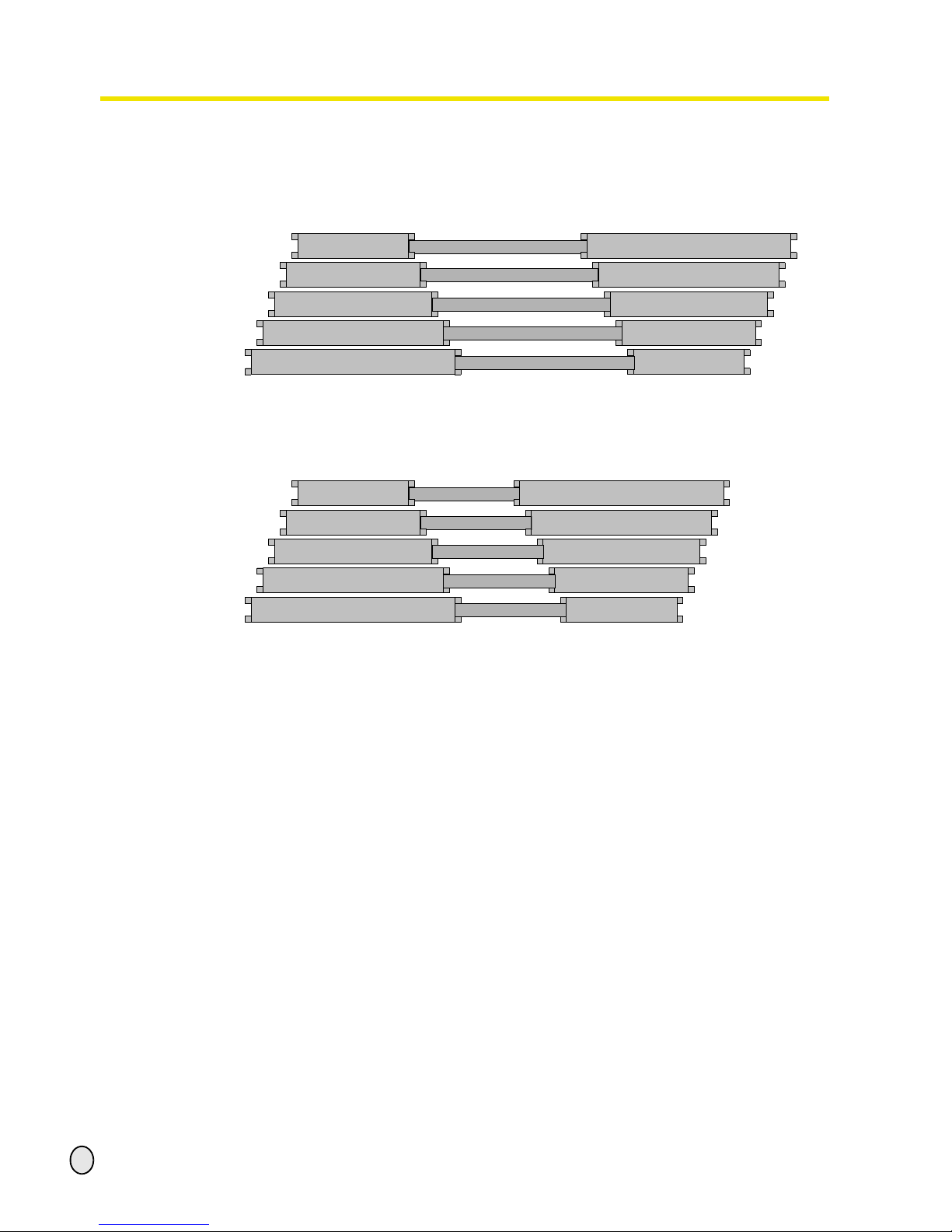
The following signs indicate if you have one of the FI protected switches described above.
We recommend you to use an FI protected switch sensitive to AC/DC. FI protected switches
sensitive to AC/DC (RCCB, type B are adequate for 1 phase and 3 phase fed frequency converters (driving regulators).
An FI protected switch type AC (only for alternating current (AC)) is not appropriate for frequency converters. FI protected switches type AC are no longer used.
„Qualification of employees“ on page 8
FI protected switch sensitive to pulse current
Typ A
FI protected switch sensitive to AC/DC
Typ B
300 mA
300 mA
Page 22

Assembly
quantum
MASCHINEN - GERMANY
© 2007
GB
Page 22 Drilling machine B 13 / B14 / B16 / B20 / B25 / B32 Version 1.2.5 18 / 01 / 2008
3.5.1 Phase inverter for 400V - machines
Change the poles by means of the phase
inverter if the turning direction of the drilling machine is not correct.
Illustr.3-9: Phase inverter
Phase inverter
Page 23

quantum
MASCHINEN - GERMANY
Handling
© 2007
GB
Page 2318 / 01 / 2008 Version 1.2.5 B 13 / B14 / B16 / B20 / B25 / B32 Drilling machine
4 Handling
4.1 Safety
Use the drilling machine only under the following conditions:
The drilling machine is in proper working order.
The drilling machine is used as prescribed.
The instruction manual has been followed.
All safety devices are installed and activated.
All malfunctions should be eliminated immediately. Stop the machine immediately at an event of
any malfunction in operation and make sure it cannot be started up accidentally or without
authorization.
Notify the person responsible immediately of any modification.
„Safety during operation“ on page 12
4.2 Control and indicating elements
4.2.1 B 13, B 14
Illustr. 4-1: quantum B 13
pulley drive with housing
handle for V-belt tension
lever for spindle sleeve feed
drilling machine table
table height adjustment
ON / OFF switch with
EMERGENCY STOP
function
drill depth stop
drill chuck guard
Page 24

Handling
quantum
MASCHINEN - GERMANY
© 2007
GB
Page 24 Drilling machine B 13 / B14 / B16 / B20 / B25 / B32 Version 1.2.5 18 / 01 / 2008
4.2.2 B 16, B 20, B 25, B 32, B20 Vario, B25 Vario, B32 Vario
Illustr. 4-2: quantum B20 Vario
4.2.3 Drill depth stop
When drilling several holes of the same
depth, you can use the drill depth stop.
• Bei B16 / B20 / B25 / B32:
Unscrew the locking screw and turn the
graduated collar until the required drill
depth superimposes with the pointer.
Retighten the locking screw .
Illustr.4-3: Drill depth stop
B16 - B32
pulley drive with housing
handle for V-belt tension
lever for spindle sleeve feed
drill depth stop
drilling machine table
table height adjustment
adjustment for the inclination of
the drilling machine table
potentiometer speed
regulation (only Vario)
ON / OFF switch with
EMERGENCY STOP
function
reversing switch
drill chuck guard
clamping lever
locking screw
drill depth stop
scale
Page 25

quantum
MASCHINEN - GERMANY
Handling
© 2007
GB
Page 2518 / 01 / 2008 Version 1.2.5 B 13 / B14 / B16 / B20 / B25 / B32 Drilling machine
• For B 13 / B14:
Adjust the limit screw to the required drilling
depth.
The spindle may only be lowered to the
required drill depth.
Illustr.4-4: Drill depth stop
B13 - B14
4.2.4 Inclination of the drilling machine table
The drilling machine table can be inclined
to the right or to the left.
Loosen the fastening screws.
For B16 / B20 / B25 / B32:
Pull out the threaded pin.
Illustr.4-5: Fastening screw
INFORMATION
If the threaded pin may not be pulled out, the seat may be loosened by turning the nut clockwise.
Adjust the required angle by means of the scale.
Retighten the fastening screw firmly.
INFORMATION
The threaded pin is only provided for correct positioning of a horizontal level of the drilling table.
limit screw
drill depth stop
scale
fastening screw
threaded pin
scale
Page 26

Handling
quantum
MASCHINEN - GERMANY
© 2007
GB
Page 26 Drilling machine B 13 / B14 / B16 / B20 / B25 / B32 Version 1.2.5 18 / 01 / 2008
4.3 Speed alternation
WARNING!
Only open the cover hood when the drilling machine is disconnected from the electrical
power supply.
Close and screw the covering hood after each modification of the number of revolutions.
Disconnect the machine from the electrical
power supply.
Detach the screws on the protective
cover.
Open the protective cover of the belt
drive.
Illustr.4-6: Clamping screw V-belt
tension
Untighten the clamping screw of the V-belt tension and push the motor in direction of the drill
chuck.
Type Vario:
Adjust the required speed with the potentiometer. Depending on the position of the V-belts on
the V-belt pulleys you will get a certain speed range.
„Speed table“ on page 27
INFORMATION
The drilling machine B 20 , B 25 and B 32 are equipped with a handle by which you may push
the motor in direction of the drill chuck.
Thus the pre-tension of the V-belts is loosened.
Put the V-belt/-s onto the required V-belt pulley/-s.
Retighten the V-belt/-s
Close and rescrew the cover.
ATTENTION!
Make sure that the tension of the V-belts is correct.
If the tension of the V-belts is too high or too low, it may lead to damages. The V-belts are
well tightened if the they could be squeezed approximately 1 cm.
V-belt pulleys
clamping screw
V-belt tension
Page 27
quantum
MASCHINEN - GERMANY
Handling
© 2007
GB
Page 2718 / 01 / 2008 Version 1.2.5 B 13 / B14 / B16 / B20 / B25 / B32 Drilling machine
4.3.1 Speed table
Speed table B13 / B14
Illustr. 4-7: Speed table quantum B13 / B14
Speed table B16
Illustr. 4-8: Speed table quantum B16
2435
spindle
engine
1807
1314
837
619
2100
spindle
engine
1255
787
579
459
Page 28

Handling
quantum
MASCHINEN - GERMANY
© 2007
GB
Page 28 Drilling machine B 13 / B14 / B16 / B20 / B25 / B32 Version 1.2.5 18 / 01 / 2008
Speed table B20 / B25
Illustr. 4-9: Speed table B20 / B25
spindle
533
376
268
796
453
323
1029
1274
516
1783
2209
1257
engine
center pulleys
Page 29

quantum
MASCHINEN - GERMANY
Handling
© 2007
GB
Page 2918 / 01 / 2008 Version 1.2.5 B 13 / B14 / B16 / B20 / B25 / B32 Drilling machine
Speed table B20 Vario / B25 Vario
Illustr. 4-10: Speed table B20 Vario / B25 Vario
spindle
526
371
264
785
447
318
1014
1256
509
1757
2177
1239
engine
center pulleys
1367
963
686
2041
1161
827
2636
3265
1323
3500
3500
3221
32
22
16
47
27
19
61
75
31
105
131
74
15% 100% 225%
Page 30

Handling
quantum
MASCHINEN - GERMANY
© 2007
GB
Page 30 Drilling machine B 13 / B14 / B16 / B20 / B25 / B32 Version 1.2.5 18 / 01 / 2008
Speed table B32
Speed table B 32
spindle
379
288
167
1368
585
339
1106
1970
489
engine
center pulleys
Page 31

quantum
MASCHINEN - GERMANY
Handling
© 2007
GB
Page 3118 / 01 / 2008 Version 1.2.5 B 13 / B14 / B16 / B20 / B25 / B32 Drilling machine
Speed table B32 Vario
Illustr. 4-11: Speed table B 32 Vario
4.4 Standard values for speeds with HSS – Eco – twist drill
The preceding specifications are standard values. In some cases, it might be advantageous
to increase or to decrease those values.
Never do without coolant or lubricant when drilling.
Do not center rust-free materials (e.g. VA – or NIRO sheet metals), as the material will
harden and the drills will quickly get blunt.
The workpieces must always be tightened rigidly and strongly (vice, screw clamp).
spindle
373
284
165
1349
576
335
1090
1942
482
engine
center pulleys
15% 100% 225%
970
739
429
3507
1498
870
2835
3500
1253
22
17
10
81
35
20
65
117
29
material
drill diameter
cooling
3)
2345678910
steel, unalloyed,
up to 600 N7mm
2
n 1)5600 3550 2800 2240 2000 1600 1400 1250 1120
E
f
2)
0,04 0,063 0,08 0,10 0,125 0,125 0,16 0,16 0,20
structural steel, alloyed,
hardened and tempered, up
to 900N/mm
2
n 3150 2000 1600 1250 1000 900 800 710 630
E/Öl
f 0,032 0,05 0,063 0,08 0,10 0,10 0,125 0,125 0,16
structural steel, alloyed,
hardened and tempered, up
to 1200 n/mm
2
n 2500 1600 1250 1000 800 710 630 560 500
Öl
f" 0,032 0,04 0,05 0,063 0,08 0,10 0,10 0,125 0,125
rustproof steels of up to 900
N/mm
2
e.g. X5CrNi18 10
n 2000 1250 1000 800 630 500 500 400 400
Öl
f 0,032 0,05 0,063 0,08 0,10 0,10 0,125 0,125 0,16
1): speed [ n ] in r/min
2): feed [ f ] in mm/r
3): cooling: E = emulsion; Öl = cutting oil
Page 32
Handling
quantum
MASCHINEN - GERMANY
© 2007
GB
Page 32 Drilling machine B 13 / B14 / B16 / B20 / B25 / B32 Version 1.2.5 18 / 01 / 2008
4.5 Drill chuck
4.5.1 Gear rim-drill chuck
Open the drill chuck by means of the key
for chucks.
Illustr.4-12: gear rim-drill chuck
ATTENTION!
Make sure that the chucked tool is positioned firmly and correctly.
4.5.2 Disassembly of the drill chuck
WARNING!
Disassemble the drill chuck only when the drilling machine is disconnected from the
electrical power supply.
Disconnect the drilling machine from the electrical power supply.
The conical connection can be separated with a plastic or a rubber hammer.
4.6 Cooling
The friction generated during rotation can cause the edge of the tool to become very hot.
The tool should be cooled during the drilling process. Cooling the tool with a suitable cooling
lubricant ensures better working results and a longer edge life of the tools.
This is best realized by a separate cooling equipment. If there is no cooling equipment included
in the delivery volume, you can cool by means of a spray gun or a washing bottle.
ATTENTION!
Danger of injury due to brushes getting caught or pulled in.
Use a spray gun or a washing bottle for cooling.
INFORMATION
Use a water-soluble and non-polluant drilling emulsion which can be obtained from authorized
distributors.
Make sure that the cooling agent is being collected.
Respect the environment when disposing any lubricants and cooling agents.
Follow the manufacturer’s disposal instructions.
4.7 Before starting the working process
Before you start working, select the required speed. It is depending on the drilling diameter and
on the material used.
upper part
gear rim drill chuck
opening for the
key for chucks
Page 33
quantum
MASCHINEN - GERMANY
Handling
© 2007
GB
Page 3318 / 01 / 2008 Version 1.2.5 B 13 / B14 / B16 / B20 / B25 / B32 Drilling machine
„Speed table“ on page 27
WARNING!
For drilling jobs, it is necessary to clamp the workpiece firmly to prevent the bit catching
on the piece. Example of suitable clamping devices include a machine vice or clamping
jaws.
Put a wooden or plastic board beneath the workpiece to avoid drilling through to the work table,
vice, etc.
If necessary, adjust the required drill depth by means of the drill depth stop in order to achieve a
constant result.
Use a dust remover unit while working with wood. Sawdust can be health hazardous. Also use a
suitable protective mask for any work which generates dust.
4.8 During the working process
The spindle sleeve feed is being p erformed by th e star grip. Make sur e that the feed is being at
a regular pace and not too fast.
The reset of the spindle sleeve is being performed by a track recoil spring.
WARNING!
Danger of clothing and / or long hair getting caught.
• Make sure to wear a well-fitting work suit during drilling work.
• Do not use gloves.
• If necessary, wear a hairnet.
ATTENTION!
Danger of collision by the levers of the star grip.
Do not let the star grip get loose when resetting the drill sleeve.
Thin bits break easily.
In case of deep drilling, remove the bit from time to time, to remove drilling chips from the bore
hole. Some drops of oil reduce friction and ensure a longer edge life of the bit.
CAUTION!
Danger of crushing! Do not place your hand between the drill head and the spindle
sleeve.
Page 34

Maintenance
quantum
MASCHINEN - GERMANY
© 2007
GB
Page 34 Drilling machine B 13 / B14 / B16 / B20 / B25 / B32 Version 1.2.5 18 / 01 / 2008
5 Maintenance
In this chapter you will find important information about
• inspection,
• maintenance,
• repair of the drilling machine.
The diagram below shows which of these headings each task falls under.
Illustr. 5-1: Maintenance –Definition according to DIN 31051
ATTENTION!
Properly-performed regular maintenance is an essential prerequistite for
• safe operation,
• fault-free operation,
• long service life of the drilling machine and
• the quality of the products you manufacture.
Installations and equipment from other manufactures must also be in optimum condition.
ENVIRONMENTAL PROTECTION
During work on the spindle nose and the apron, make sure that
• collector vessels are used, with sufficient capacity for the amount of liquid to be collected,
• liquid and oils are not spilt on the ground.
Clean up any spilt liquid or oils immediately using proper oil-absorption methods and dispose of
them in accordance with current legal requirements on the environment.
Cleaning up spillages
Do not re-introduce liquids spilt outside the system during repair or as a result of leakage from
the reserve tank: collect them in a collecting vessel to be disposed of.
Disposal
Never dump oil or other pollutant substances in water inlet s, river s o r channels.
Maintenance
Inspection Maintenance
Repair
Measuring Rough cleaning Mending
Testing Fine cleaning Replacing
Conserving
Lubricating
Completing
Replacing
Readjusting
Adjusting
Page 35

quantum
MASCHINEN - GERMANY
Maintenance
© 2007
GB
Page 3518 / 01 / 2008 Version 1.2.5 B 13 / B14 / B16 / B20 / B25 / B32 Drilling machine
Used oils must be delivered to a collection centre. Consult your superior if you do not know
where the collection centre is.
5.1 Safety
WARNING!
The consequences of incorrect maintenance and repair work may include:
• very serious injury to personnel working on the drilling machine,
• damage to the drilling machine.
• Only qualified personnel should carry out maintenance and repair work on the drilling
machine.
5.1.1 Preparation
WARNING!
Only carry out work on the drilling machine if it has been switched off using the main
switch and secured with a padlock to prevent the machine from being turned on.
Attach a warning label.
5.1.2 Restarting
Before restarting run a safety check.
„Safety check“ on page 11
WARNING!
Before connecting the machine you must check that
• there is no danger for personnel
• the drilling machine is undamaged.
5.2 Inspection and maintenance
The type and extent of wear depends to a large extent on individual usage and service conditions. Therefore, the indicated intervals only apply fo r the approved conditions.
Interval Where? What? How?
start of shift
after each
maintenance or
repair operation
drilling machine
„Safety check“ on page 11
Page 36

Maintenance
quantum
MASCHINEN - GERMANY
© 2007
GB
Page 36 Drilling machine B 13 / B14 / B16 / B20 / B25 / B32 Version 1.2.5 18 / 01 / 2008
every week
attachment screws
V-belt tension
• Check if the attachment screws for the V-belt tension on the left
and right side of the drilling head are well fastened.
• Check if the V-belts are well tightened. Checking the tension of
the V-belts,
„Speed alternation“ on page 26.
Illustr. 5-2: B20 drilling head on the right
every month
tripod and rack
lubricate
• Lubricate the tripod regularly with commercial oil.
• Lubricate the rack regularly with commercial grease (e.g. friction bearing grease).
Illustr. 5-3: tripod
every six
months
V-belts on the drilling head
visual inspection
• Check the V-belt on the drilling head that it is not being porous
or used.
Illustr. 5-4: V-belts
Interval Where? What? How?
guide rail screws
on the right
tripod
toothed rack
V-belts
Page 37

quantum
MASCHINEN - GERMANY
Maintenance
© 2007
GB
Page 3718 / 01 / 2008 Version 1.2.5 B 13 / B14 / B16 / B20 / B25 / B32 Drilling machine
5.3 Repair
For any repair work, request the assistance of an employee of Optimum Maschinen GmbH’s
technical service or send us the drilling machine.
If the repairs are carried out by qualified technical staff, they must follow the indications given in
this manual.
Optimum Maschinen GmbH does not take responsiblity nor does it guarantee against damage
and operating malfunctions resulting from failure to observe this operating manual.
For repairs only use
• faultless and suitable tools,
• original parts or parts from series expressly authorized by Optimum Maschinen GmbH.
every six
months
electric
check
Check the electrical equipment/ parts of the drilling machine.
„Qualification of employees“ on page 8
Interval Where? What? How?
Page 38

Ersatzteile - Spare parts B13, B14, B16, B20, B25, B32
quantum
MASCHINEN - GERMANY
38
S:\Betriebsanleitungen\drilling_machines\B13_14_16_20_25_32\B13-B32_parts\B13-B32_parts.fm
18.1.08
6 Ersatzteile - Spare parts B13, B14, B16, B20, B25, B32
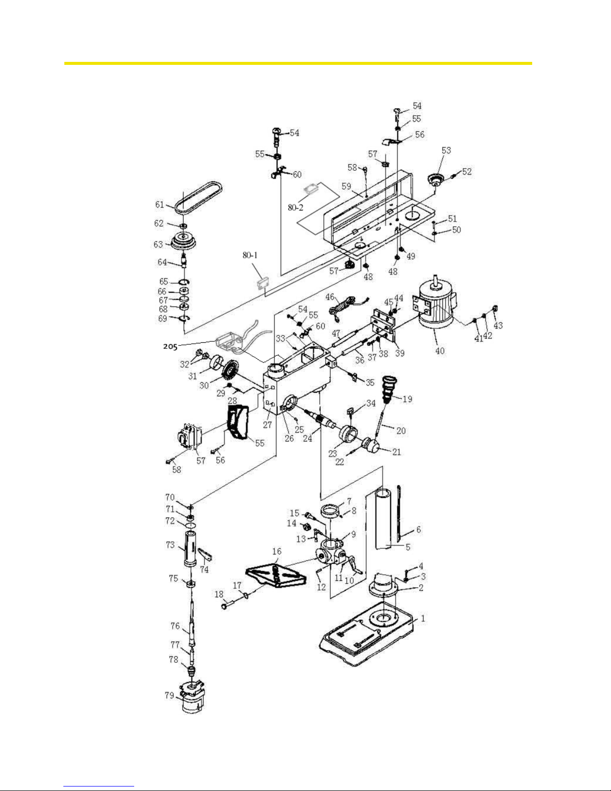
6.1 Ersatzteilzeichnung - Parts drawing B13 / B14
Abb.6-1: B13 / B14
Page 39
quantum
MASCHINEN - GERMANY
Ersatzteile - Spare parts B13, B14, B16, B20, B25, B32
18.1.08
S:\Betriebsanleitungen\drilling_machines\B13_14_16_20_25_32\B13-B32_parts\B13-B32_parts.fm
39
6.2 Bohrfutterschutz B13, B14 - Drill chuck protection B13, B14
6.2.1 Ersatzteilliste - Parts list B13 / B14
202
201
203
Pos.
Bezeichnung Designation
Menge grösse
Artikel-
nummer
Qty. Size Item no.
1 Maschinenfuss Base 1 0300813101
2 Säulenflansch Column seat 1 0300813102
3 Scheibe Washer 3 M 8
4 Federscheibe Spring Washer 3 M 8
5 Schraube Screw 3 M8x16
6 Bohrsäule Column 1
B13
B14
0300813106
0300814106
7 Klemmhebel Clamp Handl e 1 0300813107
8 Schraube Screw 1 M12x26 0300813108
9 Federscheibe Spring Washer 1 M 12
10 Bohrtisch Work Table 1 0300813110
11 Bohrtischhalter Support 1 0300813111
12 Bolzen Bolt 1 M6x25
13 Mutter Nut 1 M6
14 Getriebeachse Gear Axis (pinion shaft) 1 0300813114
15 Hebel lever 3 0300813115
16 Knopf knob 3 0300820121
17 Bolzen Bolt 2 M8x10
18 Stellgriff Adjusting Handle 1 0300813118
19 Druckfeder Compress Spring 1 0300813119
20 Motorstange Motor Pole 1 0300813120
21 Elastische Unterlegscheibe Cushion Washer 1 0300813121
22 Schraube Screw 3 M6x12
23 Scheibe Washer 3 M 6
24 Motorbodenplatte Motor Bottom Board 1 0300813124
25 Scheibe Washer 2 M 6
26 Schraube Screw 2 M8x16
27 Motor Motor 1 0300813127
28 Motorriemenscheibe Motor pulley 1 0300813128
29 Bolzen Bolt 1 M6x10
30 Scheibe Washer 4 M 6
31 Bolzen Bolt 4 M8x12
32 Mutter Nut 1 M5x12
33 Scheibe Washer 1 M 5
34 Hebegriff Lifting Handle 1 0300813134
Page 40

Ersatzteile - Spare parts B13, B14, B16, B20, B25, B32
quantum
MASCHINEN - GERMANY
40
S:\Betriebsanleitungen\drilling_machines\B13_14_16_20_25_32\B13-B32_parts\B13-B32_parts.fm
18.1.08
35 Riemengehäuse pulley cover 1 0300813135
36 Bolzen Bolt 2 M4x12
37 Scheibe Washer 2 M 4
38 Kabelklemme Wire Clamp 2 M 4
39 Kabelöse Ring for Wire 1 0300813139
40 Scheibe Washer 2 0300813140
41 Kabelöse Ring for Wire 4 0300813141
42 Anschlusskabel Plug Wire 2 0300813142
43 Gehäuse Case 1 0300813143
44 Schaltgehäuse Switch Box 1 0300813144
46 Bolzen Bolt 1 0300813146
47 Schalter Switch 1 0300813147
48 Mutter Nut 1 M10x1
49 Mutter Nut 1 M10x1
50 Federgehäuse Cover of Spring 1 0300813150
51 Rückholfeder Turbination Spring 1 0300813151
52 Anzeigevorrichtung Indicator 1 0300813152
53 Mutter Nut 1 0300813153
54 Mutter Nut 1 0300813154
55 Stange Rod 1 0300813155
56 Haltevorrichtung Holder 1 0300813156
57 Mutter Nut 1 M6
58 Keilriemen V-belt 1 10 x 650 0391050
59 Spindelriemenscheibe Spindle pulley 1 0300813159
60 Bolzen Bolt 1 M6 x 10
61 Achsenring Ring of Axis 1 22 0300813161
62 Achsenabdeckung Square Axis Cover 1 0300813162
63 Bohrungsring Ring of Hole 1 40 0300813163
64 Kugellager Bearing 1 6203 0406203.2R
65 Kugellager Bearing 1 6203 0406203.2R
66 Bohrungsring Ring of Hole 1 40 0300813166
67 Achsenring Ring of Axis 1 12 0300813167
68 Kugellager Bearing 1 6201 0406201.2R
69 Gummiunterlegscheibe Rubber Washer 1 0300813169
70 Pinole Pinole 1 0300813170
71 Kugellager Bearing 1 6201 0406201.2R
72 Spindel Spindle 1 0300813172
73 Bohrfutter chuck 1 3050654
74 Kabelklemme Wire Clamp 1 0300813174
201
Bohrfutterschutz Sichtschutz-
scheibe
Drill chuck protection view sealing
pane
1 03008131201
202 Arm Bohrfutterschutz Arm drill chuck protection 1 03008131202
203 Halterung Bohrfutterschutz Fixing drill chuck protection 1 03008131203
203-1 Endlagenschalter Bohrfutterschutz
End position switch drill chuck protec-
tion
1 030081312031
205 Gehäuse (Trafo) Housing (trafo) 1 03008131205
T eile ohne Abbildung - Parts without illustration
0 Schalterkappe gelb switch cap yellow 1 0300813180
0 Abdeckung Lüfter (B13) cover fan (B13) 1 0300813182
0 Kondensator (Motor) condensator (engine) 1 0300813176
0 Lüfterrad (Motor) fan wheel (engine) 1 0300813178
0 Bohrfutterschutz alter typ Drill chuck protection old type 1
3008135
+
3008136
0 Reed Kontakt Reed contact 1 0302024192
0 Transformator Transformer 1 03008131301
0 Schütz Contactor 1 03008131302
0 Schaltkasten (leer) Electric box (empty) 1 0300813179
0 Nutenstein t-nut 1 0300813177
Komplett-Sätze - Complete sets
Pinole komplett pinole complete 1 0300813170CPL
201-1 Bohrfutterschutz komplett Drill chuck protection complete 1 030081312011
Säule kpl. column compl. 1 0300813106CPL
Halter kplt. Holder cplt. 1 03008131201CPL
Gehäuse (Trafo) kpl. Housing (transformer) compl. 1 03008131205CPL
Pos.
Bezeichnung Designation
Menge grösse
Artikel-
nummer
Qty. Size Item no.
Page 41
quantum
MASCHINEN - GERMANY
Ersatzteile - Spare parts B13, B14, B16, B20, B25, B32
18.1.08
S:\Betriebsanleitungen\drilling_machines\B13_14_16_20_25_32\B13-B32_parts\B13-B32_parts.fm
41
6.3 Ersatzteilzeichnung - Parts drawing B 16
Abb.6-2: B16
Page 42

Ersatzteile - Spare parts B13, B14, B16, B20, B25, B32
quantum
MASCHINEN - GERMANY
42
S:\Betriebsanleitungen\drilling_machines\B13_14_16_20_25_32\B13-B32_parts\B13-B32_parts.fm
18.1.08
6.4 Bohrfutterschutz B16 - Drill chuck protection B16
6.4.1 Ersatzteilliste - Parts list B16
202
201
203
Pos.
Bezeichnung Designation
Menge grösse
Artikelnum-
mer
Qty. Size Item no.
1 Maschinenfuss Base 1 0300816101
2 Säulenflansch Column Seat 1 0300816102
3 Scheibe Washer 3 M 8
4 Schraube Screw 3 M8x25
5 Säule Column 1 0300816105
6 Zahnstange Rack 1 0300816106
7 Säulenring Column Ring 1 0300816107
8 Bolzen Bolt 1 M8x10
9 Bohrtischhalter Support 1 0300816109
10 Kurbel crank 1 0300820110
11 Schraube Screw 1 M5x10
12 Bolzen Bolt 1 0300816112
13 Klemmhebel Cl amp Handle 1 0300816113
14 Zahnrad Gear 1 0300816114
15 Schneckenrad Gear Wheel 1 0300816115
16 Bohrtisch Work Table 1 0300816116
17 Scheibe Washer 1 M 12
18 Schraube Screw 1 M12x25
19 Knopf Knob 1 0300820121
20 Hebel Lever 1 0300816120
21 Hebelsitz Lever Seat 1 0300816121
22 Bolzen Pin 1 0300816122
23 Skalenring Dial 1 0300816123
24 Schaftritzel pinion shaft 1 0300816124
25 Niete Rivet 1 0300816125
26 Zeiger Pointer 1 0300816126
27 Gehäuse Case 1 0300816127
28 Bolzen Bolt 1 M8x16
29 Mutter Nut 1 M 8
30 Rückholfeder Turbination Spring 1 0300816130
31 Federgehäuse Cover of Spring 1 0300816131
32 Mutter Nut 2 M 12x1,5
33 Bolzen Bolt 2 M8x6
34 Feststellknopf Tight Knob 1 0300816134
35 Einstellknopf Adjust Knob 1 0300816134
36 Motorstange Motor Pole 1 0300816136
37 Schraube Screw 4 M8x16
Page 43

quantum
MASCHINEN - GERMANY
Ersatzteile - Spare parts B13, B14, B16, B20, B25, B32
18.1.08
S:\Betriebsanleitungen\drilling_machines\B13_14_16_20_25_32\B13-B32_parts\B13-B32_parts.fm
43
38 Scheibe Washer 4 M 8
39 Motorbodenplatte Motor Bottom Board 1 0300816139
40 Motor Motor 1 0300816140
41 Scheibe Washer 1 8
42 Federscheibe Spring Washer 1 8
43 Mutter Nut 1 M8
44 Mutter Nut 1 M8
45 Scheibe Washer 1 8
46 Kabel Wire Plug 1 0300816146
47 Motorstange Motor Pole 1 0300816147
48 Mutter Nut 1 M6
49 Gummiring Rubber Ring 1 0300816149
50 Scheibe Washer 4 6
51 Bolzen Bolt 1 M6x8
52 Bolzen Bolt 1 M5x22
53 Motorriemenscheibe Motor Pulley 1 0300816153
54 Bolzen Bolt 2 M6x16
55 Schalte r gehäuse S witch housing 2 0300816155
56 Schraube screw 1 0300816156
57 Schalter switch 1 0300813147
58 Bolzen Bolt 1 M5x8
59 Riemengehäuse Pulley Cover 1 0300816159
60 Presskabelblock Press Wire Block 2 0300816160
61 Keilriemen V-belt 1 0391100
62 Mutter Nut 1 0300816162
63 Spindelriemenscheibe Spindle pulley 1 0300816163
64 Schaft pinion 1 0300816164
65 Bohrungsring Ring for Hole 1 0300816165
66 Kugellager Bearing 1 6204 0406204.2R
67 Kugellagerring Ring for Bearing 1 0300816167
68 Kugellager Bearing 1 6204 0406204.2R
69 Bohrungsring Ring for Hole 1 0300816165
70 Schaftring Ring for Shaft 1 0300816170
71 Kugellager Bearing 1 6201 0406201.2R
72 Gummiring Rubber ring 1 0300816172
73 Pinole Pinole 1 0300816173
74 Austreiber Drill Drift 1 0300816174
75 Kugellager Bearing 1 6205 0406205.2R
76 Spindel Spindle 1 0300816176
77 Kegeldorn Taper mandril 1 0300816177
78 Bohrfutter chuck 1 3050626
79 Bohrfutterschutz alter typ Drill chuck protection old type 1
3008205
+
3008206
201
Bohrfutterschutz Sichtschutz-
scheibe
Drill chuck protection view sealing
pane
1 03008161201
202 Arm Bohrfutterschutz Arm drill chuck protection 1 03008161202
203 Halterung Bohrfutterschutz Fixing drill chuck protection 1 03008161203
203-1 Endlagenschalter Bohrfutterschutz
End position switch drill chuck protec-
tion
1 030081312031
205 Gehäuse (Trafo) Housing (trafo) 1 03008161205
Teile ohne Abbildung - Parts without illustration
0 Kondensator capacitor 1 0300816182
0 Reed Kontakt Reed contact 1 0302024192
0 Transformator Transformer 1 03008131301
0 Schütz Contactor 1 03008131302
0 Schaltkasten Motor (leer) Electric box motor (empty) 1 0300816181
0 Nutenstein t-nut 1 0300813177
0 Motorlüfterdeckel motor fan cover 1 0300816180
0 O-Anzeige O-Pointer 1 0322025
Komplett-Sätze - Complete sets
Pinole Komplett Pinole complete 1 0300816173CPL
Säule mit Halter Column with base ring 1 0300816105CPL
201-1 Bohrfutterschutz komplett Drill chuck protection complete 1 030081612011
Gehäuse (Trafo) kpl. Housing (transformer) compl. 1 03008161205CPL
Pos.
Bezeichnung Designation
Menge grösse
Artikelnum-
mer
Qty. Size Item no.
Page 44

Ersatzteile - Spare parts B13, B14, B16, B20, B25, B32
quantum
MASCHINEN - GERMANY
44
S:\Betriebsanleitungen\drilling_machines\B13_14_16_20_25_32\B13-B32_parts\B13-B32_parts.fm
18.1.08
6.5 Ersatzteilzeichnung - Parts drawing B20 / B25 (Vario)
Abb.6-3: B20 / B25
Page 45

quantum
MASCHINEN - GERMANY
Ersatzteile - Spare parts B13, B14, B16, B20, B25, B32
18.1.08
S:\Betriebsanleitungen\drilling_machines\B13_14_16_20_25_32\B13-B32_parts\B13-B32_parts.fm
45
6.6 Bohrfutterschutz B20, B25 - Drill chuck protection B20, B25
6.6.1 Ersatzteilliste - Parts list B20 / B25 (Vario)
202
201
203
Pos.
Bezeichnung Designation
Menge grösse
Artikel-
nummer
Qty. Size Item no.
1 Maschinenfuss Base 1 0300820101
2 Säulenflansch 1
B20 0300820102
B25 0300825302
3 Scheibe Washer 4 0300820103
4 Schraube Screw 4 10 0300820104
5 Säule Column 1
B20 0300820105
B25 0300825305
6 Zahnstange Rack 1
B20 0300820106
B25 0300825306
7 Säulenring Colum Ring 1 0300820107
8 Bolzen Bolt 1 M 6x10
9 Bohrtischhalter Support 1 0300820109
10 Kurbel Crank 1 0300820110
11 Schraube Screw 1 M 6x15
12 Getriebewelle Gear Shaft 1 0300820112
14 Schraube Screw 1 M 6x15
15 Klemmhebel Clamp Handle 1 0300820115
16 Arm Arm 1 0300820116
17 Bohrtisch W ork Table 1 0300820117
18 Klemmhebel Clamp Handle 1 0300820118
19 Zahnrad Gear 1 0300820119
20 Schneckenrad Worm Gear 1 0300820120
21 Knopf Knob 3 0300820121
22 Hebel Lever 3 0300820122
23 Hebelsitz Lever Seat 1 0300820123
24 Bolzen Pin 1 5 x 32 0300820124
25 Skalenring Dial 1 0300820125
26 Ritzelwelle Pinion Shaft 1 0300820126
27 Gehäuse Case 1 0300820127
28 Bolzen Bolt 1 M10 x 10
29 Mutter Nut 1 M 10
30 Rückholfeder Turbination Spring 1 0300820130
31 Federgehäuse Cover of Spring 1 0300820131
32 Mutter Nut 2 M12x1,5
33 Schraube Screw 1 0300820133
34 Bolzen Bolt 2 M10 x 10
35 Nockenwelle Camshaft 1 0300820135
36 Schraube Screw 1 0300820136
Page 46

Ersatzteile - Spare parts B13, B14, B16, B20, B25, B32
quantum
MASCHINEN - GERMANY
46
S:\Betriebsanleitungen\drilling_machines\B13_14_16_20_25_32\B13-B32_parts\B13-B32_parts.fm
18.1.08
37 Motorstange Motor Pole 1 0300820137
38 Schraube Screw 4 M8 x 25
39 Scheibe Washer 9 8
40 Motorbodenplatte Motor Bottom Board 1 0300820140
41
Motor Motor 1
230 V 0300820141
400 V 0300825341
42 Federscheibe Lock washer 4 8
43 Mutter nut 4 M 8
44 Mutter nut 2 M 10
45 Scheibe Washer 2 10
46 Motorstange Motor Pole 1 0300820146
47 Schraube Screw 1 M 6x12
48 Nocke Cam 1 0300820148
49 Schaltergehäuse Switch housing 1
230 V 0300820149
400 V 0300820349
51 Bolzen Bolt 1 0300820151
52 Schalter Switch 1
230 V 0300820152
400 V 0300820352
53 Anschlusskabel Power Wire 1
230V 0300820153
400V 0300825353
54 Kabelblock Wire Block 1 0300820154
55 Bolzen Bolt 1 M 6x10
56 Scheibe Washer 4 6
57 Bolzen Bolt 4 M 6x12
58 Riemenscheibe Motor Motor pulley 1 0300820158
59 Bolzen Bolt 1 M 5 x 6
60 Bohrungsring Ring for Hole 1 35 0300820160
61 Kugellager Bearing 2 6201 0406201.2R
62 Keilriemen V-belt 1 10 x 610 0300820162
63 Riemenscheibe Mitte Middle Pulley 1 0300820163
64 Zentrierteil Centering Device 1 0300820164
65 Hebel Lifting Handle 1 0300820165
66 Riemenabdeckung Pulley Cover 1 0300820166
67 Keilriemen V-belt 1 10 x 625 0300820167
68 Rundmutter Round Nut 1 0300820168
69 Spindelriemenscheibe Spindle pulley 1 0300820169
70 Schaft Pinion 1 0300820170
71 Bohrungsring Ring for Hole 1 47 0300820171
72 Kugellager Bearing 1 6005 0406005.2R
73 Lagerscheibe Bearing Washer 1 0300820173
74 Kugellager Bearing 1 6005 0406005.2R
75 Bohrungsring Ring for Hole 1 47 0300820175
76 Spindelring Ring for Spindle 1 15 0300820176
77 Kugellager Bearing 1 6005 0406204.2R
78 Elastischer Unterlegscheibe Cushion Washer 1
B25
B20
0300825378
0300820178
79 Pinole Pinole 1 0300820179
80 Austreiber Drill Drift 1 0300820180
81 Kugellager Bearing 1 6204 0406204.2R
82
Spindel B20 Spindle B20 1 MT2 0300820182
Spindel B25 Spindle B25 1 MT3 0300825382
83 Kegeldorn Taper Mandriel 1
B20
B25
3050659
3050660
84 Bohrfutter Chuck 1 3050626
85 Bohrfutterschutz alter typ Drill chuck protection old type 1
B20
B25
3008205
+
3008206
3008207
+
3008206
Pos.
Bezeichnung Designation
Menge grösse
Artikel-
nummer
Qty. Size Item no.
Page 47

quantum
MASCHINEN - GERMANY
Ersatzteile - Spare parts B13, B14, B16, B20, B25, B32
18.1.08
S:\Betriebsanleitungen\drilling_machines\B13_14_16_20_25_32\B13-B32_parts\B13-B32_parts.fm
47
86 Ring für Kabelschutz Ring for Protecting Wire 1 0300820186
87 Mutter Nut 1 0300820187
88 Kabelklemme Press Wire 1 0300820188
89 Scheibe Washer 1 0300820189
90 Bolzen Bolt 1 0300820190
201
Bohrfutterschutz Sichtschutz-
scheibe
Drill chuck protection view sealing
pane
1 03008201201
202 Arm Bohrfutterschutz Arm drill chuck protection 1 03008201202
203 Halterung Bohrfutterschutz Fixing drill chuck protection 1 03008201203
203-1 Endlagenschalter Bohrfutterschutz
End position switch drill chuck protec-
tion
1 030081312031
205 Gehäuse (Trafo) Housing (trafo) 1 03008201205
Teile ohne Abbildung - Parts without illustration
0 Kondensator capacitor 1 0300820192
0 Reed Kontakt Reed contact 1 0302024192
0 Transformator Transformer 1
0 Schütz Contactor 1
0 Schaltkasten (leer) Electric box (empty) 1 0300820192
O-Anzeige O-Pointer 0300820193
Komplett-Sätze - Complete sets
Pinole Komplett Spindle sleeve complete
1 B20 0300820179CPL
1 B25 0300825379CPL
201-1 Bohrfutterschutz komplett Drill chuck protection complete 1 030082012011
Säule kplt. Column complete 1 B20 0380020105CPL
Lüfterraddeckel fan cover 0300820193
Gehäuse (Trafo) kpl. Housing (transformer) compl. 1 03008201205CPL
Pos.
Bezeichnung Designation
Menge grösse
Artikel-
nummer
Qty. Size Item no.
Page 48
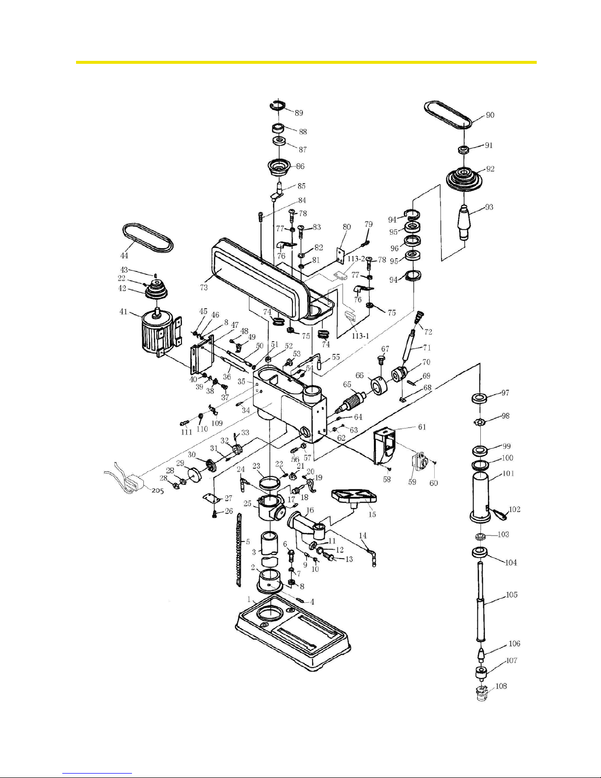
Ersatzteile - Spare parts B13, B14, B16, B20, B25, B32
quantum
MASCHINEN - GERMANY
48
S:\Betriebsanleitungen\drilling_machines\B13_14_16_20_25_32\B13-B32_parts\B13-B32_parts.fm
18.1.08
6.7 Ersatzteilzeichnung - Parts drawing B32 (Vario)
Abb.6-4: B32
Page 49

quantum
MASCHINEN - GERMANY
Ersatzteile - Spare parts B13, B14, B16, B20, B25, B32
18.1.08
S:\Betriebsanleitungen\drilling_machines\B13_14_16_20_25_32\B13-B32_parts\B13-B32_parts.fm
49
6.8 Bohrfutterschutz B32 - Drill chuck protection B32
6.8.1 Ersatzteilliste - Parts list B32 (Vario)
202
201
203
Pos.
Bezeichnung Designation
Menge grösse
Artikelnum-
mer
Qty. Size Item no.
1 Maschinenfuss Base 1 0300832301
2 Säulenflansch Column Sea t 1 0300832302
3 Säule Column 1 0300832303
4 Arretierbolzen Lock Bolt 1 M 10x10
5 Zahnstange Rack 1 0300832305
6 Schraube Screw 5 M12 x 40
9 Bolzen (A) Pin (A) 1 0300832309
10 Mutter Nut 1 M6
14 Klemmhebel Clamp Handle 1 0300832314
15 Bohrtisch W ork Table 1 0300832315
16 Arm Arm 1 0300832316
17 Bolzen Pin 1 0300832317
18 Schneckenrad Worm Wheel 1 0300832318
19 Kurbel Crank 1 0300832319
20 Schraube bolt 1 M 6 x 12
21 Zahnrad Gear 1 0300832321
23 Säulenring Column Ring 1 0300832323
24 Klemmhebel Clamp Handle 1 0300832324
25 Bohrtischhalter Support 1 0300832325
26 Bolzen Bolt 4 M 5 x 8
27 Abdeckung Cover Board 1 0300832327
29 Federgehäuse Cover of Spring 1 0300832329
30 Rückholfeder Turbination Spring 1 0300832330
31 Federstift Spring Pin 1 6 x 21
32 Federsitz Spring Seat 1 0300832332
33 Federstift Spring Pin 1 3 x 15
34 Bolzen Bolt 1 M10 x 12
35 Gehäuse Case 4 0300832335
36 Motorstange Motor Pole 4 0300832336
37 Schraube Screw 4 0300832337
38 Mutter Nut 4 M8
41
Motor Motor 1 400 V 0300832341
42 Motorriemenscheibe Motor pulley 1 neuer typ / new type 0300832342
42 Motorriemenscheibe Motor pulley 1 alter typ / old type 0323238
43 Paßfeder Key 1 0300832343
44 Keilriemen V - belt 1
neuer typ / new type
13 x 750
0323274
Page 50

Ersatzteile - Spare parts B13, B14, B16, B20, B25, B32
quantum
MASCHINEN - GERMANY
50
S:\Betriebsanleitungen\drilling_machines\B13_14_16_20_25_32\B13-B32_parts\B13-B32_parts.fm
18.1.08
44 Keilriemen V - belt 1 15x740Li (old type) 0323259
45 Mutter Nut 2 0300832345
47 Motorbodenplatte Motor Bottom Board 1 0300832347
49 Nocke Cam 1 0300832349
50 Motorstange Motor Pole 1 0300832350
52 Gummidichtung Rubber Washer 1 0300832352
53 Bolzen (A) Bolt (A) 1 0300832353
54 Bolzen Bolt 1 0300832354
55 Nockenwelle Cam Shaft 1 0300832355
56 Bolzen Bolt 1 0300832356
57 Mutter Nut 1 M10
58 Bolzen Bolt 4 0300832358
59 Schalter Switch 1 0300820352
60 Bolzen Bolt 3 0300832360
61 Schaltergehäuse Switch Housing 1 0300832361
62 Zeiger Pointer 1 0300832362
63 Bolzen Bolt 1 0300832363
64 Bolzen Bolt 1 0300832364
65 Schaftritzel Pinion Shaft 2 0300832365
66 Skalenring Dial 1 0300832366
67 Bolzen (B) Bolt (B) 1 40 0300832367
68 Klemmstück Clamping Piece 1 0300832368
69 Federstift Spring Pin 1 6 0300832369
70 Hebelsitz Lever Seat 1 0300832370
71 Hebel Lever 3 0300832371
72 Knopf Knob 3 0300832372
73 Riemengehäuse Pulley Cover 1 0300832373
74 Schutz Kabelring Protect Wire Ring 2 0300832374
75 Mutter Nut 2 0300832375
76 Druckkabelblock Press Wire Block 2 0300832376
77 Scheibe Washer 2 0300832377
78 Bolzen Bolt 2 0300832378
79 Bolzen Bolt 1 M5x8
80 Quardatisches Bord Square Board 1 0300832380
81 Scheibe Washer 4 6
82 Federring Spring Washer 4 6
83 Bolzen Bolt 4 M6x16
84 Bolzen Bolt 1 0300832384
85 Zentrierstück Centering Device 1 0300832385
86 Keilriemenscheibe Mitte Middle pulley 1 neuer typ / new type 0300832386
86 Keilriemenscheibe Mitte Middle pulley 1 alter typ / old type 0323235
87 Kugellager Bearing 1 0406202.2R
89 Klammer Circlip 1 40 0300832389
90 Keilriemen V - belt 1
gates Super HC MN
SPA 832 (new type)
13 x 850
0323273
90 Keilriemen V - belt 1 15x845Li (old type) 0323258
91 Mutter Nut 1 0300832391
92 Spindel-Keilriemenscheibe Spindle pulley 1 neuer typ / new type 0300832392
92 Spindel-Keilriemenscheibe Spindle pulley 1 alter typ / old type 0323237
93 Schaft Pinion 1 0300832393
94 Klammer Circlip 1 0300832394
95 Kugellager Bearing 1 627 040627.2R
96 Ring Ring 1 0300832396
97 Rundmutter Round nut 1 0300832397
98 Scheibe Washer 1 0300832398
99 Kugellager Bearing 1 6206 0406206.2R
100 Scheibe Washer 1 03008323100
101 Pinole Pinole 1 03008323101
102 Austreiber Drill Drift 1 03008323102
103 Kugellager Bearing 1 6007 0406007.2R
104 Kugellager Bearing 1 6208-2Z 0406208.2R
105 Spindel Spindle 1 03008323105
106 Kegeldorn Taper Mandril 1 3050661
107 Bohrfutter chuck 1 3050626
Pos.
Bezeichnung Designation
Menge grösse
Artikelnum-
mer
Qty. Size Item no.
Page 51

quantum
MASCHINEN - GERMANY
Ersatzteile - Spare parts B13, B14, B16, B20, B25, B32
18.1.08
S:\Betriebsanleitungen\drilling_machines\B13_14_16_20_25_32\B13-B32_parts\B13-B32_parts.fm
51
108 Bohrfutterschutz Chuck guard old type 1
3008325
+
3008326
109 Druckkabelblock Press Wire Block 1 03008323109
110 Scheibe Washer 1 03008323110
111 Bolzen Bolt 1 03008323111
201
Bohrfutterschutz Sichtschutz-
scheibe
Drill chuck protection view sealing
pane
1 03008201201
202 Arm Bohrfutterschutz Arm drill chuck protection 1 03008201202
203 Halterung Bohrfutterschutz Fixing drill chuck protection 1 03008201203
203-1 Endlagenschalter Bohrfutterschutz
End position switch drill chuck protec-
tion
1 030081312031
205 Gehäuse (Trafo) Housing (trafo) 1 03008323205
Teile ohne Abbildung - Parts without illustration
0 Reed Kontakt Reed contact 1 0302024192
0 Transformator Transformer 1 03008131301
0 Schütz Contactor 1 03008131302
0 Schaltkasten (leer) Electric box (empty) 1 03008131112
0 Skala Bohrtisch Scale table 1 03008131113
0 Skala Skalenring Scale for dial 1 03008131114
Komplett-Sätze - Complete sets
Pinole Komplett pinole complete 03008323101CPL
101-1 Bohrfutterschutz komplett Drill chuck protection complete 1 030082011011
Gehäuse (Trafo) kpl. Housing (transformer) compl. 1 03008323205CPL
Pos.
Bezeichnung Designation
Menge grösse
Artikelnum-
mer
Qty. Size Item no.
Page 52
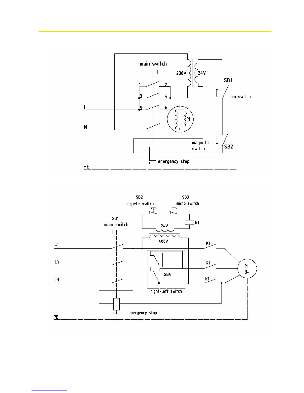
Ersatzteile - Spare parts B13, B14, B16, B20, B25, B32
quantum
MASCHINEN - GERMANY
52
S:\Betriebsanleitungen\drilling_machines\B13_14_16_20_25_32\B13-B32_parts\B13-B32_parts.fm
18.1.08
6.9 Schaltplan - Wiring diagram B13-B20 (230V)
6.10 Schaltplan - Wiring diagram B20-B32 (400V)
Page 53

quantum
MASCHINEN - GERMANY
Ersatzteile - Spare parts B13, B14, B16, B20, B25, B32
18.1.08
S:\Betriebsanleitungen\drilling_machines\B13_14_16_20_25_32\B13-B32_parts\B13-B32_parts.fm
53
6.11 Schaltplan - Wiring diagram B20Vario-B32Vario (230V)
Page 54

Malfunctions
quantum
MASCHINEN - GERMANY
© 2007
GB
Page 54 Drilling machine B 13 / B14 / B16 / B20 / B25 / B32 Version 1.2.5 18 / 01 / 2008
7 Malfunctions
Malfunction
Cause/
possible effects
Solution
FI protective switch disengages
• a non-common FI protective
switch is used
• „Power supply“ on page 21
Noise during working
• Spindle turning dry.
• Tool blunt or is being incorrectly
secured.
• Grease spindle
• Use new tool and check securing (fixed setting of the bit, drill
chuck and morse taper).
Bit "burnt"
• Incorrect speed/ feed too fast
• The chips have not been
removed from the bore hole
•Bit blunt
• Operating without or too little
cooling agent
• Select another speed
• Extract the bit more often
• Sharpen or replace bit
• Use coolant
Bit tip moves, bore hole
is not circular
• Hard fibre in the workpiece
• unequal length of the cutting spiral or unequal angles in the bit.
• Bit deformed
• Replace bit or re-sharpen it
Defective bit
• No support used • Place a wooden board beneath
the workpiece and secure them
to one another
Bit running off-centre or
„hopping“
• Bit deformed
• Bearings worn down
• Bit badly secured
• Drill chuck defective
• Replace bit
• Have the bearings replaced
• Secure the bit properly
• Replace the drill chuck
Impossible to introduce
drill chuck or morse taper
• There is dirt, grease or oil on the
inner conical surface of the drill
chuck or on the conical surface of
the drilling spindle
• Clean surfaces well
• Keep surfaces free of grease
Engine does not start
• engine connected wrongly
• Defective fuse
• Have it checked by authorized
personnel
Overheating of motor and
lack of power
• Engine overloaded
• Insufficient mains voltage
• Engine connected wrongly
• Disconnect immediately and
have it checked by authorized
personnel
• Have it checked by authorized
personnel
Precision of the work
deficient
• Heavy and unbalanced or twisted
workpiece
• Inexact horizontal position of the
workpiece holder
• Balance workpiece statically and
secure it without straining
• Adjust workpiece holder
Drilling spindle sleeve
does not return to its initial position
• Spindle restoring spring does not
work properly
• locking pin is being introduced
• Check spindle restoring spring,
replace it, if necessary
• pull out locking pin
The drilling sleeve may
not be moved downwards.
• The locking pin is introduced
• The drill depth setting is not
released
• Pull out the locking pin
• Release the drill depth setting
Page 55

quantum
MASCHINEN - GERMANY
Malfunctions
© 2007
GB
Page 5518 / 01 / 2008 Version 1.2.5 B 13 / B14 / B16 / B20 / B25 / B32 Drilling machine
The temperature of the
spindle bearing is too
high
• The bearings are worn out
• The pretension of the bearings is
too high
• Working with high drilling revolutions for a long period of time
•Replace
• Reduce clearance in the bearing
for (taper roller bearings)
• Reduce drilling revolutions / feed
Ratteling of the working
spindle when working
with rough workpiece
surfaces
• Clearance of the bearing too
wide
• The working spindle moves up
and down
• The adjusting gib has come loose
• Clamping chuck is loose
• Tool is blunt
• Workpiece is loose
• Adjust the clearance of the bearing or exchange the bearing
• Adjust the clearance of the bearing
• Adjust the gib with the adjusting
screw to the correct clearance
• control, retighten
• Sharpen the tool or replace it
• Clamp the workpiece properly
Malfunction
Cause/
possible effects
Solution
Page 56

Appendix
quantum
MASCHINEN - GERMANY
© 2007
GB
Page 56 Drilling machine B 13 / B14 / B16 / B20 / B25 / B32 Version 1.2.5 18 / 01 / 2008
8 Appendix
8.1 Copyright
© 2007
This documentation is copyright. All derived rights are also reserved, especially those of transla-
tion, re-printing, use of figures, broadcast, reproduction by photo-mechanical or similar means
and recording in data processing systems, neither partial nor total.
The company reserves the right to make technical alternations without prior notice.
8.2 Terminology/Glossary
Term Explanation
drill drift tool to release the bit or the drill chuck from the drill
spindle
drill chuck drill holding fixture
drilling head upper part of the drilling machine
drill sleeve fixed hollow shaft which runs in the drill spindle
drill spindle shaft driven by the engine
drilling machine table support face, clamping surface
morse taper cone of the drill or of the drill chuck
sleeve lever manual control for the drill feed
quick action drill chuck drill holding fixture to be clamped manually
workpiece part to be drilled, part to be machined
tool bit, countersink, etc.
locking pin pin to hold the drill sleev e at a ce rtain heigh t in or de r
to disassemble the drill chuck or the tool
Page 57

quantum
MASCHINEN - GERMANY
Appendix
© 2007
GB
Page 5718 / 01 / 2008 Version 1.2.5 B 13 / B14 / B16 / B20 / B25 / B32 Drilling machine
8.3 Warranty
Within the term of warranty, the company Optimum warrants for a perfect quality of its products
and will reimburse any cost for overhaul or exchange of defective parts in case of construction
error, fault in material and / or defect of fabrication.
The term of warranty for commercial use is 12 months and for use as an amateur it is 24
months. Condition for a warranty claim due to construction errors, faults in material and / or
defects of fabrication is:
• Proof of purchase and that the instructions for use had been followed.
In order to assert the claim of warranty, you have to present a typescript original receipt of
purchase. It must comprise the complete address, date of purchase and type designation of
the product.
The instruction for use for the corresponding device as well as the safety information are to
be observed. Damages due to operator’s mistakes may not be accepted as warranty claims.
• Correct use of the devices.The products of the company Optimum had been designed and
built for certain purposes. They are listed in the operation ma nu a l.
The warranty claim may not be accepted if the operating manual is not being followed properly or if it is used for a purpose which has not been intended or with improper accessory.
• Maintenance work and cleaning.
It is absolutely necessary to maintain and clean the machine in regular intervals according to
the prescriptions of the instruction for use.
By intervention of a third party, any warranty claim will expire. Maintenance work and cleaning are usually not part of the claim of warranty.
• Original spare parts
Make sure to use only original spare parts and original accessory. This can be acquired from
authorized distributors of the machine.
When other than original parts are being used, consequential damages may occur and danger of accidents will increase. Disassembled or partially disassembled devices and devices
which are repaired with foreign parts are excluded from warranty claims.
• Wearing parts
Certain components are subject to wear out by time respectively a standard wear by use on
the corresponding machine.
Among these components are e.g. V-belts, ball bearings, switches, mains cables, gaskets
and washers, etc. These wearing parts are not part of the warranty.
8.4 Disposal
Disposal of used electric and electronic machines
(Applicable in the countries of the European Union and other European countries with a separate collecting system for those devices).
The sign on the product or on its packing indicates that the product must not be handles as common household waist, but that is needs to be delivered to a central collection point for recycling.
Your contribution to the correct disposal of this product will protect the environment and the
health of your fellow men. The environment and the health are endangered by incorrect disposal. Recycling of material will help to reduce the consumption of raw materials. Your District
Office, the municipal waste collection station or the shop where you have bought the product will
inform you about the recycling of this product.
8.5 RoHS , 2002/95/CE
The sign on the product or on its packing indicates that this product complies with the European
guideline 2002/95/EC .
Page 58

Appendix
quantum
MASCHINEN - GERMANY
© 2007
GB
Page 58 Drilling machine B 13 / B14 / B16 / B20 / B25 / B32 Version 1.2.5 18 / 01 / 2008
8.6 Product follow-up
We are required to perform a follow-up service for our products which extends beyond shipment.
We would be grateful if you could send us the following information:
• modified settings
• experiences with the drilling machine, which could be important for other users
• recurring failures
Optimum Maschinen Germany GmbH
Dr.-Robert-Pfleg er-Str. 26
D-96103 Hallstadt
Fax +49 (0) 951 - 96822 - 22
E-Mail: info@optimum-maschinen.de
Page 59

quantum
MASCHINEN - GERMANY
© 2007
GB
Page 59Stand 18 / 01 / 2008 Version 1.2.5 B 13 / B14 / B16 / B20 / B25 / B32 Drilling machine
8.7 EC - declaration of conformity
The manufacturer/
retailer:
Optimum Maschinen Germany GmbH
Dr.-Robert-Pfleger-Str. 26
D - 96103 Hallstadt
hereby declares that the following product,
type of machine: bench drill
pillar drill
designation of machine: B13, B14, B16, B20, B20
Va rio, B25, B25 Vario, B32,
B32 V ario
relevant EU directives:
machine directives 98/37/EG, Appendix II A
EMV- directive 89/336/EWG
low voltage directive 73/23/EWG
meets the provisions of the aforementioned directive, including any amendments valid
at the time of this statement.
In order to ensure conformity, the following harmonized standard in partic ular have
been applied:
EN 12717: 2001 Safety of machine tools, drilling machines
EN 62079 Editing of instructions - structure, content and illustra-
tion (IEC 62079:2001)
Hallstadt, 18 / 01 / 2008
Kilian Stürmer
(Manager)
Thomas Collrep
(Manager)
Page 60

quantum
MASCHINEN - GERMANY
© 2007
GB
Page 60 Drilling machine B 13 / B14 / B16 / B20 / B25 / B32 Version 1.2.5 18 / 01 / 2008
Index
A
Assembly ......................................................16, 17
C
Cooling .........................................................32
Copyright
......................................................56
D
Declaration of conformity ..............................59
Dimensions
...................................................15
Drill chuck
.....................................................32
Drill depth stop
.............................................24
E
EC - declaration of conformity ......................59
Electric
..........................................................13
Environmental conditions
.............................15
Extent of supply
............................................16
H
Handling .......................................................23
I
Inclination of the drilling machine table ........25
Inspection
..................................................... 35
Installation
....................................................17
Installation drawings
.....................................20
M
Maintenance .................................................34
Malfunctions
.................................................54
O
ON / OFF switch ...........................................10
P
Power connection .........................................14
Power supply
................................................21
Product follow-up
..........................................58
Prohibition, warning and mandatory labels
..11
Q
Qualification of employees ...........................8
S
Safety devices ..............................................9
Speed alternation
.........................................26
Speed table
..................................................27
Spindle holding fixture
..................................14
Storage
.........................................................17
T
Technical Data .............................................14
Transport
......................................................16
U
User’s position ..............................................9
W
Warning notes ..............................................5
Warranty
.......................................................57
 Loading...