

Page 1

AIR-COOLED SCREW
LIQUID CHILLERS
INSTALLATION, OPERATION, MAINTENANCE
MODEL QTC4 STYLE A
AIR-COOLED SCREW LIQUID CHILLERS WITH
VARIABLE SPEED DRIVE
Supersedes: QTC4-NM1 (318) Form QTC4-NM1 (418)
035-24497-000
150 - 500 TONS
525 - 1750 KW
2 COMPRESSOR
60 HZ
HFC-134A
Issue Date:
April 2, 2018
LD18970
Page 2
IMPORTANT!
READ BEFORE PROCEEDING!
GENERAL SAFETY GUIDELINES
FORM QTC4-NM1
ISSUE DATE: 4/2/2018
This equipment is a relatively complicated apparatus.
During rigging, installation, operation, maintenance,
or service, individuals may be exposed to certain components or conditions including, but not limited to:
heavy objects, refrigerants, materials under pressure,
rotating components, and both high and low voltage.
Each of these items has the potential, if misused or
handled improperly, to cause bodily injury or death. It
is the obligation and responsibility of rigging, installation, and operating/service personnel to identify and
recognize these inherent hazards, protect themselves,
and proceed safely in completing their tasks. Failure
to comply with any of these requirements could result
in serious damage to the equipment and the property in
which it is situated, as well as severe personal injury or
death to themselves and people at the site.
This document is intended for use by owner-authorized
rigging, installation, and operating/service personnel. It
is expected that these individuals possess independent
training that will enable them to perform their assigned
tasks properly and safely. It is essential that, prior to
performing any task on this equipment, this individual
shall have read and understood the on-product labels,
this document and any referenced materials. This individual shall also be familiar with and comply with
all applicable industry and governmental standards and
regulations pertaining to the task in question.
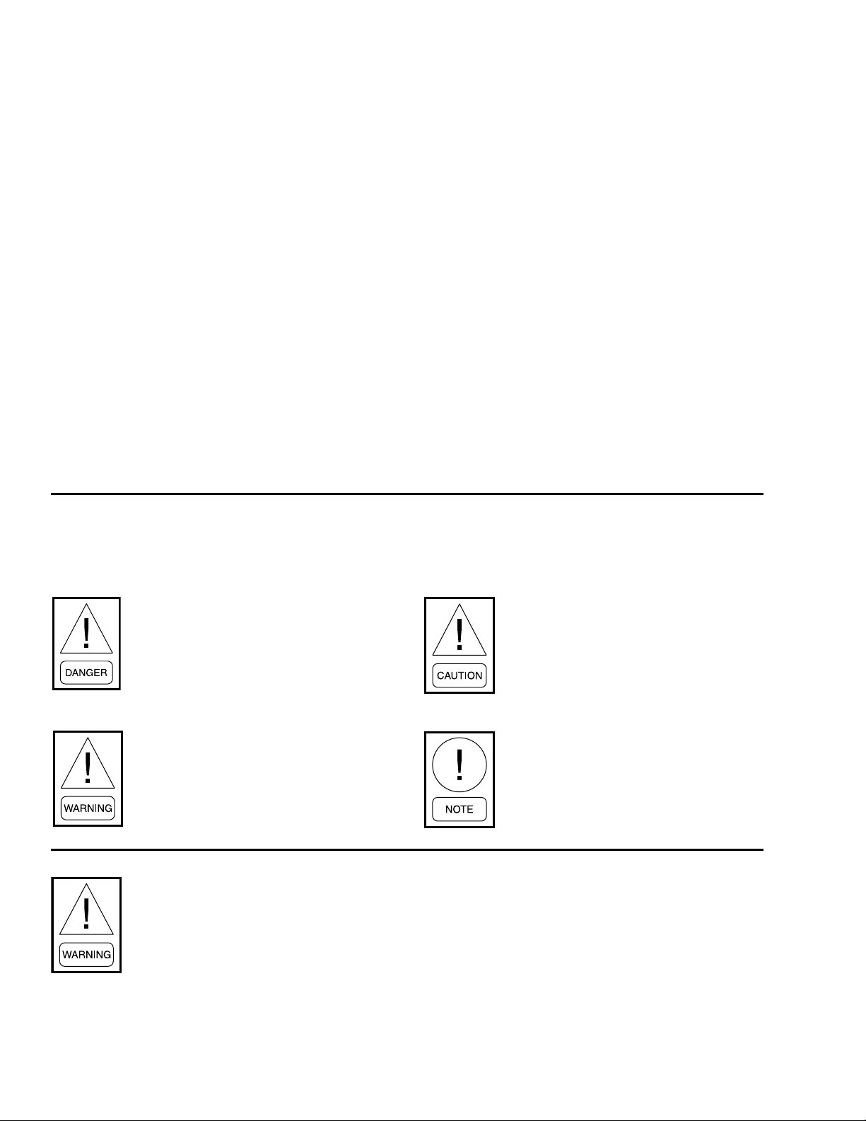
SAFETY SYMBOLS
The following symbols are used in this document to alert the reader to specific situations:
Indicates a possible hazardous situation
which will result in death or serious injury
if proper care is not taken.
Identies a hazard which could lead to
damage to the machine, damage to other
equipment and/or environmental pollution if proper care is not taken or instructions and are not followed.
Indicates a potentially hazardous situation which will result in possible injuries
or damage to equipment if proper care is
not taken.
External wiring, unless specied as an optional connection in the manufacturer’s product line, is not
to be connected inside the control cabinet. Devices such as relays, switches, transducers and controls
and any external wiring must not be installed inside the micro panel. All wiring must be in accor-
dance with Johnson Controls’ published specications and must be performed only by a qualied
electrician. Johnson Controls will NOT be responsible for damage/problems resulting from improper
connections to the controls or application of improper control signals. Failure to follow this warn-
ing will void the manufacturer’s warranty and cause serious damage to property or personal injury.
2
Highlights additional information useful
to the technician in completing the work
being performed properly.
QUANTECH
Page 3

FORM QTC4-NM1
ISSUE DATE: 4/2/2018
CHANGEABILITY OF THIS DOCUMENT
In complying with Johnson Controls’ policy for continuous product improvement, the information contained in this document is subject to change without
notice. Johnson Controls makes no commitment to
update or provide current information automatically
to the manual or product owner. Updated manuals, if
applicable, can be obtained by contacting the nearest
Johnson Controls Service office or accessing the Johnson Controls QuickLIT website at http://cgproducts.
johnsoncontrols.com.
It is the responsibility of rigging, lifting, and operating/
service personnel to verify the applicability of these
The Control/VSD Cabinet contains lethal
high AC and DC voltages. Before performing service inside the cabinet, remove
the AC supply feeding the chiller and
verify using a non-contact voltage sensor.
The DC voltage on the VSD DC Bus
will take 5 minutes to bleed off, after AC
power is removed. Always check the DC
Bus Voltage with a Voltmeter to assure
the capacitor charge has bled off before
working on the system.
NEVER short out the DC Bus to dis-
charge the lter capacitors.
NEVER place loose tools, debris, or any
objects inside the Control Panel/VSD
Cabinet.
documents to the equipment. If there is any question
regarding the applicability of these documents, rigging, lifting, and operating/service personnel should
verify whether the equipment has been modified and
if current literature is available from the owner of the
equipment prior to performing any work on the chiller.
CHANGE BARS
Revisions made to this document are indicated with a
line along the left or right hand column in the area the
revision was made. These revisions are to technical information and any other changes in spelling, grammar
or formatting are not included.
NEVER allow the Control Panel VSD
Cabinet doors to remain open if there
is a potential for rain to enter the panel.
Keep doors closed and assure all latches
are engaged on each door unless the unit
is being serviced.
ALWAYS lockout the disconnect supplying AC to the chiller.
The 1L Line Inductor will reach operating
temperatures of over 150°C (300°F.). DO
NOT open panel doors during operation.
Assure the inductor is cool whenever
working near the inductor with power
OFF.
ASSOCIATED LITERATURE
MANUAL DESCRIPTION FORM NUMBER
Equipment Pre-Startup and Startup Checklist QTC4-CL2
QTC4 Parts Guide QTC4-RP1
Equipment Standard Limited Warranty QTC-NM2
QUANTECH
3
Page 4

LD23520
UNIT NOMENCLATURE
Base Product Type
Q = Quantech
T = Variable Speed Screw
C4 = Air Cooled Design Series
Model Number
Configuration
S = Condenser Code
X = Evaporator Code
X = Compressor Code
X = Condenser Fan
& Sound Kit Code
-
QTC4 SXXX 46 AA
210
FORM QTC4-NM1
ISSUE DATE: 4/2/2018
Level / Refrigerant
A = Refrigerant R134a
B = Refrigerant R513A
Voltage
17 = 200 / 3 / 60
28 = 230 / 3 / 60
40 = 380 / 3 / 60
42 = 400 / 3 / 60
46 = 460 / 3 / 60
50 = 380-415 / 3 / 50
58 = 575 / 3 / 60
4
QUANTECH
Page 5

FORM QTC4-NM1
ISSUE DATE: 4/2/2018
TABLE OF CONTENTS
SECTION 1 - GENERAL CHILLER INFORMATION AND SAFETY ...................................................................... 11
Introduction ..................................................................................................................................................... 11
Warranty ......................................................................................................................................................... 11
Quality Assurance and Safety ........................................................................................................................ 11
Fluorinated Greenhouse Gases .....................................................................................................................12
Responsibility for Safety ................................................................................................................................. 12
About This Manual..........................................................................................................................................12
Misuse of Equipment ...................................................................................................................................... 12
Suitability for Application ....................................................................................................................... 12
Structural Support .................................................................................................................................12
Mechanical Strength .............................................................................................................................12
General Access .....................................................................................................................................12
Pressure Systems .................................................................................................................................12
Electrical ................................................................................................................................................ 12
Rotating Parts ........................................................................................................................................13
Sharp Edges ..........................................................................................................................................13
Refrigerants and Oils .............................................................................................................................13
High Temperature and Pressure Cleaning ............................................................................................13
Emergency Shutdown ...........................................................................................................................14
Safety Labels .........................................................................................................................................14
SECTION 2 - PRODUCT DESCRIPTION ............................................................................................................... 15
General System Description ........................................................................................................................... 15
Semi-Hermetic Quantech Twin-Screw Compressors .....................................................................................17
Evaporator ...................................................................................................................................................... 17
Condenser ...................................................................................................................................................... 17
Refrigerant Circuit ..........................................................................................................................................17
Electrical ......................................................................................................................................................... 17
Building Automation System Capabilities ....................................................................................................... 18
Microcomputer Control Center .......................................................................................................................18
Display Data .......................................................................................................................................... 18
Programmable Setpoints ...................................................................................................................... 18
Accessories and Options ................................................................................................................................ 19
Sound Attenuation ................................................................................................................................. 19
Fan Options .................................................................................................................................................... 19
Condenser Coils ............................................................................................................................................. 19
Condenser Coil Protection ....................................................................................................................19
Protective Chiller Panels .......................................................................................................................19
Evaporator Options ...............................................................................................................................20
Controls Options ....................................................................................................................................20
General Options ....................................................................................................................................20
Vibration Isolation .................................................................................................................................. 21
SECTION 3 - RIGGING, HANDLING AND STORAGE ..........................................................................................23
Lifting Weights ................................................................................................................................................ 23
Delivery and Storage ...................................................................................................................................... 23
Inspection ....................................................................................................................................................... 23
Moving the Chiller ........................................................................................................................................... 24
Unit Removal From Shipping Container ......................................................................................................... 24
Lifting Using Shackles .................................................................................................................................... 24
Lifting Using Lugs ........................................................................................................................................... 24
QUANTECH
5
Page 6

FORM QTC4-NM1
ISSUE DATE: 4/2/2018
TABLE OF CONTENTS (CONT'D)
SECTION 4 - INSTALLATION ................................................................................................................................ 35
Location Requirements ..................................................................................................................................35
Outdoor Installations ......................................................................................................................................35
Location Clearances ....................................................................................................................................... 35
Recommended Minimum Clearances ...................................................................................................36
Vibration Isolators ........................................................................................................................................... 37
Installation .............................................................................................................................................37
Shipping Braces .............................................................................................................................................37
Chilled Liquid Piping ....................................................................................................................................... 37
General Requirements ..........................................................................................................................37
Water Treatment ............................................................................................................................................. 38
Pipework Arrangement ................................................................................................................................... 38
Minimum Water Volume ................................................................................................................................. 38
Leaving Water Temperature Out of Range ..................................................................................................... 38
Flow Rate Out of Range ................................................................................................................................. 39
Variable Primary Flow ....................................................................................................................................40
Connection Types and Sizes .......................................................................................................................... 40
Evaporator Connections ................................................................................................................................. 40
Option Flanges ...................................................................................................................................... 41
Refrigerant Relief Valve Piping ....................................................................................................................... 41
Electrical Connection ...................................................................................................................................... 41
Power Wiring .................................................................................................................................................. 41
Power Supply Wiring ...................................................................................................................................... 42
115VAC Control Supply Transformer ..............................................................................................................42
Control Wiring ................................................................................................................................................. 42
Volts Free Contacts ........................................................................................................................................ 42
Chilled Liquid Pump Starter ...................................................................................................................42
Run Contact ..........................................................................................................................................42
Alarm Contacts ...................................................................................................................................... 42
System Inputs ................................................................................................................................................. 42
Flow Switch ...........................................................................................................................................42
Remote Run / Stop ................................................................................................................................ 43
Remote Print .........................................................................................................................................43
Optional Remote Setpoint Offset – Temperature...................................................................................43
Optional Remote Setpoint Offset – Current ........................................................................................... 43
Optional Remote Setpoint Offset – Sound Limiting ............................................................................... 43
Power Supply Wiring ...................................................................................................................................... 44
Single Point Wiring ................................................................................................................................ 44
Voltage Utilization Range ......................................................................................................................44
Dual Point Wiring ...................................................................................................................................45
Customer Control Wiring ................................................................................................................................ 46
SECTION 5 - TECHNICAL DATA ...........................................................................................................................57
Elastomeric Isolator Installation ...................................................................................................................... 84
Elastomeric Isolator Specifications ................................................................................................................. 85
One Inch Deflection Isolator Installation ......................................................................................................... 86
One Inch Deflection Spring Isolator Specifications ........................................................................................87
Two Inch Deflection Isolator Installation And Adjustment ............................................................................... 88
Two Inch Deflection, Restrained Spring Isolator Specifications .....................................................................89
6
QUANTECH
Page 7

FORM QTC4-NM1
ISSUE DATE: 4/2/2018
TABLE OF CONTENTS (CONT'D)
SECTION 6 - COMMISSIONING ............................................................................................................................91
Preparation ..................................................................................................................................................... 91
Inspection ............................................................................................................................................. 91
Refrigerant Charge ................................................................................................................................ 91
Correct System Refrigerant Charge ...................................................................................................... 91
Service and Oil Line Valves ................................................................................................................... 91
Compressor Oil .....................................................................................................................................91
Fans .....................................................................................................................................................92
Isolation / Protection .............................................................................................................................. 92
Control Panel .........................................................................................................................................92
Power Connections ...............................................................................................................................92
Grounding ..............................................................................................................................................92
Water System ........................................................................................................................................92
Flow Switch ...........................................................................................................................................92
Temperature Sensor(s) .......................................................................................................................... 92
Programmed Options ............................................................................................................................92
Programmed Settings ...........................................................................................................................92
Date and Time ....................................................................................................................................... 92
Start/Stop Schedule ..............................................................................................................................93
Setpoint and Remote Offset .................................................................................................................. 93
First Time Start Up .........................................................................................................................................93
Interlocks ............................................................................................................................................... 93
Unit Switch ............................................................................................................................................93
Startup ................................................................................................................................................... 93
Oil Pressure ...........................................................................................................................................93
Loading ..................................................................................................................................................93
Condenser and Fan Rotation ................................................................................................................93
System Charge ......................................................................................................................................93
General Operation ......................................................................................................................................... 93
Operation in Sub-freezing Conditions ...................................................................................................94
Unit Maintenance and Shutdown in Sub-freezing Conditions ..............................................................94
SECTION 7 - OPERATION .....................................................................................................................................95
Operating Controls .........................................................................................................................................95
Unit Switch ............................................................................................................................................95
Keypad ..................................................................................................................................................95
Keypad Data Entry Mode ......................................................................................................................96
Display ...................................................................................................................................................96
Anti-recycle Timer ..................................................................................................................................96
Evaporator Pump Control ...................................................................................................................... 96
Evaporator Heater Control ....................................................................................................................96
Alarms ...................................................................................................................................................97
Chiller Run Contact ...............................................................................................................................97
Flow Switch Control ...............................................................................................................................97
Remote Run / Stop ................................................................................................................................ 97
Basic Operating Sequence ............................................................................................................................. 97
Start Sequence and Loading ................................................................................................................. 97
Unit Warning ...................................................................................................................................................97
Unit Warning Operation .........................................................................................................................97
Low Battery Warning .............................................................................................................................97
QUANTECH
7
Page 8

FORM QTC4-NM1
ISSUE DATE: 4/2/2018
TABLE OF CONTENTS (CONT'D)
Microboard (331-03478-xxx) ..........................................................................................................................98
Power Supplies and LEDs .....................................................................................................................98
Power Supply Test Points ......................................................................................................................98
Conguration Jumpers .........................................................................................................................98
Communication Ports .......................................................................................................................... 100
Building Automation System (BAS) Communications ..................................................................................100
Using Communications Protocol .........................................................................................................100
E-Link or SC-EQ Interface ............................................................................................................................ 101
SC-EQ or E-Link BAS Communications Card .............................................................................................. 103
E-Link ..................................................................................................................................................107
VSD ..................................................................................................................................................... 107
Program Update ........................................................................................................................................... 107
Data Logging ................................................................................................................................................ 107
Invalid Number of Compressors Warning............................................................................................108
Invalid Serial Number Warning ............................................................................................................108
Unit Safeties ................................................................................................................................................. 109
Unit Safety Operation .......................................................................................................................... 109
High Ambient Temp Fault .................................................................................................................... 109
Low Ambient Temp Fault ..................................................................................................................... 109
Low Leaving Chilled Liquid Temp Fault ............................................................................................... 109
VSD Communications Failure Fault ....................................................................................................109
System Safeties (Faults) .............................................................................................................................. 110
System Safety (Fault) Operation ......................................................................................................... 110
High Discharge Pressure Cutout (Software) Fault .............................................................................. 110
High Discharge Pressure Cutout (HPCO) (Hardware) Fault .............................................................. 111
Low Suction Pressure Cutout (Software) Fault ................................................................................... 111
Low Motor Current Cutout Fault .......................................................................................................... 111
High Differential Oil Pressure Cutout Fault ......................................................................................... 111
Low Differential Oil Pressure Cutout Fault .......................................................................................... 112
High Discharge Temperature Cutout Fault .......................................................................................... 11 2
Low Discharge Superheat Cutout Fault .............................................................................................. 112
Discharge Pressure Load Limiting/Unloading ..................................................................................... 112
Suction Pressure Load Limiting/Unloading ......................................................................................... 113
Sensor Failure Cutout Fault ................................................................................................................ 113
High Motor Temperature Cutout Fault ................................................................................................. 114
System Control Voltage Cutout Fault .................................................................................................. 114
Eductor Clog Fault ............................................................................................................................... 114
SECTION 8 - MICROPANEL ................................................................................................................................ 115
Unit Data Key ............................................................................................................................................... 118
System Data Keys 1 Through 4....................................................................................................................120
VSD Data Key ..............................................................................................................................................123
Operating Hours / Start Counter Key ...........................................................................................................124
History Key ................................................................................................................................................... 125
Setpoints Key ...............................................................................................................................................132
Program Key ................................................................................................................................................134
Options Key .................................................................................................................................................. 137
Date/Time and Schedule Keys .....................................................................................................................140
Manual Override Key .................................................................................................................................... 143
Print Key ....................................................................................................................................................... 144
System Switches Key ................................................................................................................................... 147
8
QUANTECH
Page 9

FORM QTC4-NM1
ISSUE DATE: 4/2/2018
TABLE OF CONTENTS (CONT'D)
SECTION 9 - MAINTENANCE .............................................................................................................................. 149
General Requirements .................................................................................................................................149
Weekly Maintenance ...........................................................................................................................149
Unit Status ........................................................................................................................................... 149
Refrigerant Leaks ................................................................................................................................ 149
Operating Conditions ...........................................................................................................................149
Compressor Oil Level .......................................................................................................................... 149
Refrigerant Charge .............................................................................................................................. 149
Adding Charge to a System ................................................................................................................149
Refrigerant Removal, Evacuation and Charging a QTC4 Chiller ................................................................150
Refrigerant Removal ...........................................................................................................................150
Evacuating a System ...........................................................................................................................150
Charging Refrigerant into a System ....................................................................................................151
Microchannel Coil Cleaning .......................................................................................................................... 151
Scheduled Maintenance ...................................................................................................................... 151
Maintenance Requirements for QTC4 Chillers ............................................................................................. 152
SECTION 10 - DECOMMISSIONING, DISMANTLING AND DISPOSAL ............................................................161
General ......................................................................................................................................................... 161
Temperature ................................................................................................................................................. 162
QUANTECH
9
Page 10

FORM QTC4-NM1
ISSUE DATE: 4/2/2018
LIST OF FIGURES
FIGURE 1 - QTC4 Air-Cooled Screw Liquid Chiller with Variable Speed Drive ...................................................... 15
FIGURE 2 - Chiller Control System ......................................................................................................................... 16
FIGURE 3 - View of Control Center User Interface ................................................................................................. 18
FIGURE 4 - Lift Lug to remove unit from shipping container ................................................................................... 24
FIGURE 5 - Accessory Lifting lugs ..........................................................................................................................24
FIGURE 6 - Acceptable Minimum Clearances Around / Between Unit(S) ............................................................... 36
FIGURE 7 - Pipework Arrangement ........................................................................................................................ 38
FIGURE 8 - Leaving Water Temperature Out of Range Suggested Layout ............................................................ 39
FIGURE 9 - Suggested Layout For Applications With Flow Rates Less Than The Evaporator
Minimum Allowable Flow Rate .............................................................................................................39
FIGURE 10 - Suggested Layout For Applications With A Flow Rate Greater Than The Evaporator
Maximum Allowable Flow Rate ..........................................................................................................39
FIGURE 11 - Victaulic Groove ................................................................................................................................. 40
FIGURE 12 - Flange Attachment ............................................................................................................................. 41
FIGURE 13 - Single Point Power Wiring .................................................................................................................44
FIGURE 14 - Dual Point Power Wiring .................................................................................................................... 45
FIGURE 15 - Customer Control Connections .........................................................................................................46
FIGURE 16 - QTC4 Dimensions .............................................................................................................................76
FIGURE 17 - Keyboard and Display........................................................................................................................95
FIGURE 18 - New 331-03478-xxx Microboard ........................................................................................................ 99
FIGURE 19 - Control Board Connections for BAS Communications ....................................................................103
LIST OF TABLES
TABLE 1 - Unit Rigging ........................................................................................................................................... 26
TABLE 2 - Minimum Evaporator Tube Removal Clearance ....................................................................................36
TABLE 3 - Evaporator Connections Dimensions ....................................................................................................40
TABLE 4 - Electrical Lug Data ................................................................................................................................47
TABLE 5 - Physical Data - Microchannel Coil ......................................................................................................... 58
TABLE 6 - Physical Data - Round Tube Coil ..........................................................................................................62
TABLE 7 - Optional One-Pass Evaporator ..............................................................................................................64
TABLE 8 - Standard Two-Pass, Rear Inlet/Outlet Evaporator ................................................................................ 68
TABLE 9 - Optional Three-Pass Rear Inlet/Front Outlet Evaporator ......................................................................72
TABLE 10 - Isolator Selection and Mounting Locations .......................................................................................... 78
TABLE 11 - Values Required for BAS Communication ......................................................................................... 102
TABLE 12 - Real Time Error Numbers For BAS, SC-EQ or E-Link Communications Card ..................................102
TABLE 13 - Native Communications Data Map .................................................................................................... 104
TABLE 13 - Native Communications Data Map (CONT'D) ...................................................................................105
TABLE 14 - Operational and Fault / Inhibit Codes ................................................................................................ 106
TABLE 15 - Flash Card Update Error XXXXX ......................................................................................................107
TABLE 16 - Data Logging ....................................................................................................................................108
TABLE 17 - Low Differential Oil Pressure Cutout ................................................................................................. 112
TABLE 18 - Discharge Pressure Load Limiting/Unloading ...................................................................................11 3
TABLE 19 - Suction Pressure Load Limiting/Unloading ........................................................................................113
TABLE 20 - Start Inhibit Sensor Thresholds ......................................................................................................... 114
TABLE 21 - Sensor Min/Max Outputs ................................................................................................................... 122
TABLE 22 - Setpoint Limits ................................................................................................................................... 133
TABLE 23 - Programmable Operating Parameters ...............................................................................................136
TABLE 24 - Printout Types ....................................................................................................................................144
TABLE 25 - Troubleshooting Guide ......................................................................................................................153
TABLE 26 - Temperature Input Voltage Sensor (Measured Signal To Shield at the Sensor) ...............................156
TABLE 27 - Outside Air Temperature Sensor Input Voltage (Measured Signal To Shield at the Sensor) ............. 157
TABLE 28 - Pressure Transducer Output Voltage (Measured Signal To Return At The Transducer) ................... 158
TABLE 29 - Motor Temperature Sensor Resistance (Check At The Motor) ..........................................................159
TABLE 30 - SI Metric Conversion .........................................................................................................................162
10
QUANTECH
Page 11

FORM QTC4-NM1
ISSUE DATE: 4/2/2018
SECTION 1 - GENERAL CHILLER INFORMATION AND SAFETY
INTRODUCTION
Quantech QTC4 chillers are manufactured to the
highest design and construction standards ensuring
high performance, reliability and adaptability with all
types of air conditioning installations.
The unit is intended for cooling water or glycol solutions and is not suitable for purposes other than those
specified in this manual.
Rigging and lifting should only be done by a professional rigger in accordance with a written rigging and
lifting plan. The most appropriate rigging and lifting
method will depend on job specific factors, such as the
rigging equipment available and site needs. Therefore,
a professional rigger must determine the rigging and
lifting method to be used, and it is beyond the scope of
this manual to specify rigging and lifting details.
The rigger should locate the center of
gravity through trial lifts to account
possible variations in unit configurations. Contact your nearest Quantech sales office for weight data. See
SECTION 3 - RIGGING, HANDLING
AND STORAGE for more details.
This manual contains all the information required for
correct installation and commissioning of the unit,
together with operating and maintenance instructions.
The manual should be read thoroughly before attempting to operate or service the unit.
All procedures detailed in the manual, including installation, commissioning and maintenance tasks must
only be performed by suitable, trained and qualified
personnel.
The manufacturer will not be liable for any injury or
damage caused by incorrect installation, commissioning, operation or maintenance resulting from a failure
to follow the procedures and instructions detailed in
the manual.
WARRANTY
Quantech warrants all equipment and materials against
defects in workmanship and materials for a period of
eighteen months from date of shipment or 12 months
from date of startup, whichever comes first, unless
labor or extended warranty has been purchased as part
of the contract.
1
The warranty is limited to parts only replacement and
shipping of any faulty part, or sub-assembly, which has
failed due to poor quality or manufacturing errors. All
claims must be supported by evidence that the failure
has occurred within the warranty period, and that the
unit has been operated within the designed parameters
specified.
All warranty claims must specify the unit model, serial
number, order number and run hours/starts. Model and
serial number information is printed on the unit identification plate.
The unit warranty will be void if any modification to
the unit is carried out without prior written approval
from Quantech. For warranty purposes, the following
conditions must be satisfied:
• The initial start of the unit must be carried out by
trained personnel from an authorized Quantech
Service Center. Refer to SECTION 6 - COMMIS-
SIONING for more information.
• Only genuine Quantech approved spare parts,
oils, coolants, and refrigerants must be used.
• All the scheduled maintenance operations detailed
in this manual must be performed at the specied
times by suitably trained and qualied personnel.
See SECTION 9 - MAINTENANCE for more information.
• Failure to satisfy any of these conditions will
automatically void the warranty. Refer to Form
QTC4-NM2 for complete details.
QUALITY ASSURANCE AND SAFETY
QTC4 chillers are designed within EN ISO 9001 and
built within an EN ISO 9002 accredited manufacturing
organization.
ETL/ASME marked units conform to the following
standards:
• ANSI/ASHRAE 15 – Safety Code for Mechanical
Refrigeration.
• ANSI/ASHRAE 34 – Number Designation and
Safety Classication of Refrigerants.
• ANSI/NFPA 70 – National Electrical Code
(N.E.C.).
• ASME Boiler and Pressure Vessel Code, Section
VIII, Division 1.
QUANTECH
11
Page 12

SECTION 1 - GENERAL CHILLER INFORMATION AND SAFETY
FORM QTC4-NM1
ISSUE DATE: 4/2/2018
FLUORINATED GREENHOUSE GASES
• This equipment contains uorinated greenhouse
gases covered by the Kyoto Protocol.
• The global warming potential of the refrigerant
(HFC-134a) used in this unit is 1300.
• The refrigerant quantity is stated in Table 5 on
Page 58 of this document.
• The uorinated greenhouse gases in this equipment may not be vented to the atmosphere.
• This equipment should only be serviced by quali-
ed technicians.
RESPONSIBILITY FOR SAFETY
Every care has been taken in the design and
manufacturing of the unit to ensure compliance with
the safety requirements listed above. However, the
individual rigging, lifting, maintaining, operating or
working on any machinery is primarily responsible for:
• Personal safety, safety of other personnel, and the
machinery.
• Correct utilization of the machinery in accordance
with the procedures detailed in the manual.
Structural Support
Structural support of the unit must be provided as indicated in these instructions. Failure to provide proper
support may result in injury to the operator, or damage
to the equipment and/or building.
Mechanical Strength
The unit is not designed to withstand loads or stresses from adjacent equipment, pipework or structures.
Additional components must not be mounted on the
unit. Any such extraneous loads may cause structural failure and may result in injury to the operator, or
damage to the equipment.
General Access
There are a number of areas and features, which may
be a hazard and potentially cause injury when working
on the unit unless suitable safety precautions are taken.
It is important to ensure access to the unit is restricted
to suitably qualified persons who are familiar with the
potential hazards and precautions necessary for safe
operation and maintenance of equipment containing
high temperatures, pressures and voltages.
Pressure Systems
ABOUT THIS MANUAL
The contents of this manual include suggested best
working practices and procedures. These are issued for
guidance only, and they do not take precedence over
the above stated individual responsibility and/or local
safety regulations.
This manual and any other document supplied with
the unit are the property of Quantech which reserves
all rights. They may not be reproduced, in whole or
in part, without prior written authorization from an
authorized Quantech Sales Representative.
MISUSE OF EQUIPMENT
Suitability for Application
The unit is intended for cooling water or glycol solutions and is not suitable for purposes other than those
specified in these instructions. Any use of the equipment other than its intended use, or operation of the
equipment contrary to the relevant procedures may
result in injury to the operator, or damage to the
equipment.
The unit contains refrigerant vapor and liquid under
pressure, release of which can be a danger and cause injury. The user should ensure that care is taken during installation, operation and maintenance to avoid damage to
the pressure system. No attempt should be made to gain
access to the component parts of the pressure system other
than by suitably trained and qualified personnel.
Electrical
The unit must be grounded. No installation or maintenance work should be attempted on the electrical equipment without first switching power OFF,
isolating and locking-off the power supply. Servicing and maintenance on live equipment must not be
attempted. No attempt should be made to gain access to the
control panel or electrical enclosures during normal
operation of the unit.
The unit must not be operated outside the design
parameters specified in this manual.
12
QUANTECH
Page 13
FORM QTC4-NM1
ISSUE DATE: 4/2/2018
SECTION 1 - GENERAL CHILLER INFORMATION AND SAFETY
This equipment (Class A, Group 1) is
designed and manufactured for use in
an industrial environment, in accordance
with EN 61000-6-2:2005 and EN 61000-6
4:2007 (with EN 55011:2007 limits). It is
not intended to be used on a low-voltage
public network which supplies domestic
premises. Radio frequency interference
may occur if it is used on a low voltage
public network.
This equipment equipped with VSD, may generate
conducted and radiated disturbances, which may interfere with or damage susceptible connected apparatus.
Generally accepted engineering standards and practices should be followed to ensure trouble-free and EMC
compliant electrical installation. Installations must
be supervised or completed by a competent person in
accordance with EN 13313.
Special considerations depending on the application:
• Industry standard grounding or “earthing” practices for the equipment and installation
• Use of shielded or special cables (power and/or
control)
• Use of metallic conduit and/or cable trays for
power and control cables connected to equipment
• Cable segregation (in order to avoid the risk of
crosstalk or cross interference to signal cables,
the power cables shall be segregated from signal
cables)
• Dedicated isolation transformer
• Use of additional EMC lters
It is the responsibility of a designated System Integrator to take proper steps assuring the Electromagnetic
Compatibility of both equipment and installation as a
system.
Rotating Parts
1
Fan guards must be fitted at all times and not removed
unless the power supply has been isolated. If ductwork
is to be fitted, requiring the wire fan guards to be removed, alternative safety measures must be taken to
protect against the risk of injury from rotating fans.
Sharp Edges
The fins on the air-cooled condenser coils have sharp
metal edges. Reasonable care should be taken when
working in contact with the coils to avoid the risk of
minor abrasions and lacerations. The use of gloves is
recommended.
Frame rails, brakes, and other components may also
have sharp edges. Reasonable care should be taken
when working in contact with any components to avoid
risk of minor abrasions and lacerations.
Refrigerants and Oils
Refrigerants and oils used in the unit are generally nontoxic, non-flammable and non-corrosive, and pose no
special safety hazards. Use of gloves and safety glasses is, however, recommended when working on the
unit. The buildup of refrigerant vapor, from a leak for
example, does pose a risk of asphyxiation in confined
or enclosed spaces and attention should be given to
good ventilation.
Use only the refrigerant specifically designated for the
unit. Any other type of refrigerant may cause damage
to the equipment and will void the warranty.
High Temperature and Pressure Cleaning
High temperature and pressure cleaning methods
(for example, steam cleaning) should not be used
on any part of the pressure system as this may cause
operation of the pressure relief device(s). Detergents
and solvents, which may cause corrosion, should also
be avoided.
QUANTECH
13
Page 14
SECTION 1 - GENERAL CHILLER INFORMATION AND SAFETY
Emergency Shutdown
In case of emergency , the control panel is fitted with
an incoming supply circuit breaker with a red and yellow handle which can be used as the emergency stop
device. When operated it removes the electrical supply
to the inverter, fans, and control circuit thus shutting
down the unit.
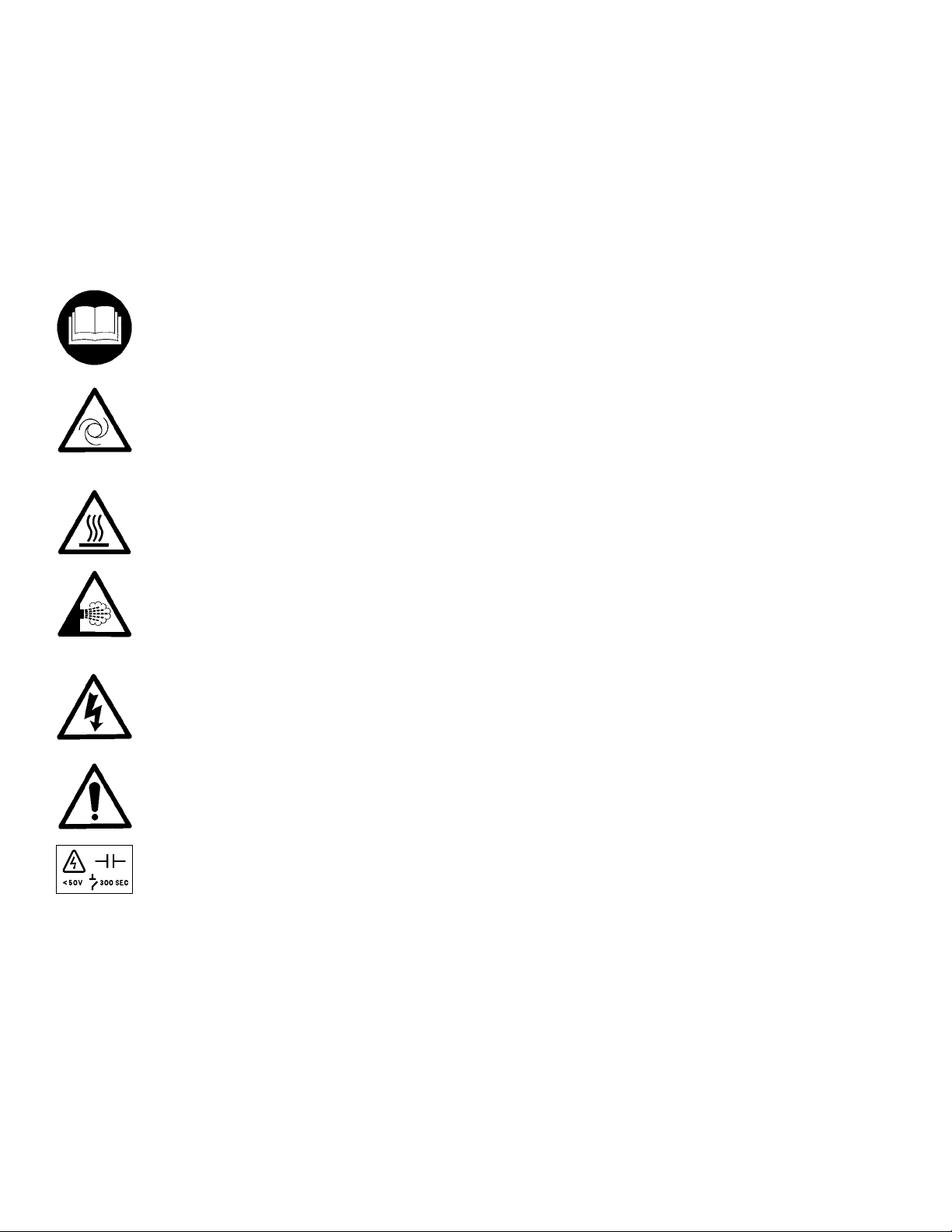
Safety Labels
White symbol on blue background.
For safe operation, read the Instructions
first.
Black symbol on yellow background.
Warning: This machine may start automatically without prior warning
FORM QTC4-NM1
ISSUE DATE: 4/2/2018
Black symbol on yellow background.
Warning: Hot surface.
Black symbol on yellow background.
Warning: Safety relief valve may discharge gas or liquid without prior warning.
Black symbol on yellow background.
Warning: Isolate all electrical sources of
supply before opening or removing the
cover, as lethal voltages may exist.
Black symbol on yellow background.
General attention symbol.
Black symbol on yellow background.
Warning: On isolating the supply it may
take up to 300 seconds for the capacitor
voltage to fall below 50 volts.
14
QUANTECH
Page 15

FORM QTC4-NM1
ISSUE DATE: 4/2/2018
SECTION 2 - PRODUCT DESCRIPTION
Quantech QTC4 chillers are designed for water or
glycol cooling. All units are designed to be located
outside on the roof of a building or at ground level.
The units are completely assembled with all interconnecting refrigerant piping and internal wiring, ready
for field installation.
Prior to delivery, the unit is pressure tested, evacuated,
and fully charged with refrigerant and oil in each of the
two independent refrigerant circuits. After assembly,
an operational test is performed with water flowing
through the evaporator to ensure that each refrigerant
circuit operates correctly.
The unit structure is manufactured from heavy gauge,
galvanized steel. Many external structural parts are
coated with “Champagne” baked-on enamel powder
paint.
All exposed power wiring is routed through
liquid-tight, non-metallic conduit.
GENERAL SYSTEM DESCRIPTION
The QTC4 chiller combines the best of modern screw
compressor design with the latest technology in
variable speed drives. The result is superior control and
efficiency in real world conditions. The VSD enables
slowing the speed of the compressor to match the load
on the system resulting in precise chilled liquid control, minimized sound, maximum energy efficiency,
and reduced cost of ownership. The VSD also provides soft starts with no electrical inrush. The lack of
heat build-up on start also enables required off time
between starts to be reduced to a period of two minutes.
The QTC4 Air-Cooled Screw Chiller utilizes many
components, which are the same or nearly the same as
a standard screw chiller of a similar size. This includes
modular frame rails, condenser, fans, compressors and
evaporator.
The chiller consists of two screw compressors in a
corresponding number of separate refrigerant circuits,
a hybrid falling film evaporator, an air-cooled condenser, receiver/flash tanks, feed valves, oil separators, and
compressor mufflers.
2
FIGURE 1 - QTC4 AIR-COOLED SCREW LIQUID CHILLER WITH VARIABLE SPEED DRIVE
QUANTECH
LD15045
15
Page 16

SECTION 2 - PRODUCT DESCRIPTION
FORM QTC4-NM1
ISSUE DATE: 4/2/2018
INPUTS
Pressure Transducers
Temperature Sensors
Switches
Liquid Flow
High Pressure
Start/Stop
Level
Customer Supplied
Contacts
COMMUNICATIONS
Building Automation
Printer Modem
3 Phase Power Line
CONTROL
PANEL
Chiller Control
Board)
Microprocessor
User Interface
Display and
Keypad
DISPLAY
KEYPAD
OUTPUTS
Relay Output Board)
Solenoids
Contactors
Alarm
Pump
Compressor Heater
Run Status
Evaporator Heater
VSD
VSD Logic Board
SCR Trigger Board
Power Components
PWM (Speed Control)
MOTOR
LD15028
AC/DC Rectier
Rectier Controller
SCR Trigger Board
Rectier
VSD Logic Board
Signal From Main Control Panel
FIGURE 2 - CHILLER CONTROL SYSTEM
Oil separators utilize no moving parts. Oil cooling is
accomplished by refrigerant leaving the eductor flashing in the suction line which cools the oil, motor and
compressor.
An integral liquid cooled, transistorized, PWM,
Variable Speed Drive (VSD) is controlled by the chiller
microprocessor control panel to start/stop, select compressors to run, and select compressor speed. Displacement Power Factor is 0. 95 at part or full load.
Compressor 1
Power Driver
(IGBT)
Compressor 2
IGBT Gate Driver
Inverter
PWM Signal
LD15158
The chiller microprocessor communicates with the
VSD Logic Board via a 3-wire RS-485 opto coupled
data link. The VSD Logic Board runs the number of
compressors required to meet the load and the compressors to the speed requested by the chiller microprocessor.
The basic system control and VSD system architecture
is shown in Figure 2 on Page 16.
16
QUANTECH
Page 17

FORM QTC4-NM1
ISSUE DATE: 4/2/2018
SECTION 2 - PRODUCT DESCRIPTION
SEMI-HERMETIC QUANTECH TWIN-SCREW COMPRESSORS
Compressors are direct drive, semi-hermetic, rotary
twin-screw type, including: muffler, temperature actuated ‘off-cycle’ heater, IP55 terminal board and precision machined cast iron housing.
Reliable suction gas cooled, high efficiency,
accessible hermetic compressor motor, full suction gas
flow through mesh screen filter, with inherent internal
thermal overload protection and external current overload on all three phases.
Continuous function, microprocessor controlled,
Variable Speed Drive (VSD) shall provide valve-less,
smooth capacity control from 100% down to 10% of
chiller capacity.
In addition, elimination of the slide valve and associated unloading components has resulted in a 50%
reduction in compressor moving parts.
EVAPORATOR
The evaporator is a shell and tube, hybrid falling film
type heat exchanger. It contains a balance of flooded
and falling film technology to optimize efficiency, minimize refrigerant charge, and maintain reliable control.
A specifically designed distribution system provides
uniform refrigerant flow for optimum performance.
Fan motors are Totally Enclosed Air-Over (TEAO),
squirrel-cage type and current protected. The direct
drive motors feature double-sealed and permanently
lubricated ball bearings, cutting down on maintenance
cost over the life of the unit.
REFRIGERANT CIRCUIT
An independent refrigerant circuit is provided per
compressor. Each circuit uses copper refrigerant pipe
formed on computer controlled bending machines to
reduce the number of brazed joints resulting in a reliable and leak resistant system.
• Discharge lines are provided with a manual compressor shutoff service valve (See Accessories
and Options on Page 19 for suction line service
valve).
• The external oil separators, with no moving parts
and designed for minimum oil carry-over, are
mounted in the discharge line of the compressor.
• Liquid line components include: high absorp-
tion removable core lter-drier, sight glasses with
moisture indicators, manual shut-off valve with
charging port, orice and electronic expansion
valve.
• An economizer (ash) tank is located in each re-
frigerant circuit to increase the system efciency.
2
CONDENSER
The QTC4 introduces micro-channel coil to the
Quantech screw compressor chiller line. The microchannel maximizes condenser heat transfer, resulting
in a smaller footprint, and reduces refrigerant charge
by as much as 50%.
Each condenser coil is a single piece all aluminum
construction including headers, tubes and fins to avoid
galvanic corrosion due to dissimilar metals. Coils and
headers are brazed as one piece. Integral sub-cooling
is included. The design working pressure is 375 PSIG
(25.9 barg).
Multiple, standard low sound, high efficiency, TEAO
motor driven fans move air through the coils. They are
dynamically and statically balanced, direct drive with
corrosion-resistant glass fiber reinforced composite
blades molded into low-noise, full airfoil cross sections, providing vertical air discharge from extended
orifices for efficiency and low sound.
ELECTRICAL
Quantech has years of experience designing Variable
Speed Drives (VSDs) specifically for chiller applications. The result is an extremely reliable air-cooled
chiller system that offers industry leading efficiency at
real world operating conditions, valve-less compressor loading/unloading, excellent capacity control, high
power factor and soft start.
Incoming single point power is standard utilizing a
lockable circuit breaker, 115VAC control transformer,
VSD, fan contactors, ON/OFF unit switch, microcomputer keypad and display, Chiller Control and VSD
Logic boards, and relay boards.
Standard design includes IP55 rating, powder painted
steel cabinet with hinged, latched, and gasket sealed
outer doors equipped with wind struts for safer servicing. The panel includes a control display access door so
that display and control features can be accessed without opening main cabinet doors. All exposed power
wiring is routed through liquid-tight, UV-stabilized,
non-metallic conduit.
QUANTECH
17
Page 18

SECTION 2 - PRODUCT DESCRIPTION
FORM QTC4-NM1
ISSUE DATE: 4/2/2018
BUILDING AUTOMATION SYSTEM CAPABILITIES
The E-Link Gateway provides an economical and
versatile connection between Quantech equipment
and open/standard protocols. It efficiently manages the communication protocols currently used by
Quantech equipment, exposing the data in a consistent,
organized, and defined fashion. The E-Link Gateway is
available as a field-installed option on QTC4. A simple
switch selection allows configuration of the required
equipment profile and output protocol, which reduces
equipment connectivity startup time.
MICROCOMPUTER CONTROL CENTER
The microcomputer control center (see Figure 3 on
Page 18) provides automatic control of chiller
operation including compressor start/ stop and load/
unload anti-recycle timers, condenser fans, evaporator pump, evaporator heater, unit alarm contacts and
run signal contacts. The microcomputer control center comes online as soon as the main power switch on
the unit is switched on; immediately, the microcomputer control center will begin to check all variables
with a frequency ranging from 30 seconds to almost
continuous monitoring.
The microprocessor controls the unit’s capacity by matching the actual leaving chilled water
temperature (LCWT) to the user-defined setpoint.
Factors that may cause the system’s actual LCWT to
fluctuate are changes in ambient temperature, loop
flow rate, load, and loop volume. The control system
reacts to such changes by adjusting the number of compressors that are on and the loading of each compressor
in order to keep the LCWT at the setpoint.
• Compressor Run Hours
• Compressor Number of Starts
• Oil Pressure and Temperature (per Compressor)
• Evaporator Pump Status
• Evaporator Heater Status
• History Data for Last Twenty Normal Shutdowns
• History Data for Last Ten Shutdown Faults
Programmable Setpoints
• Chiller On/Off
• Chilled Liquid (Water or Glycol)
• Local or Remote Control
• Units of Measure (Imperial or SI)
• System Lead / Lag
• Remote Temperature Reset
• Remote Current Limit
• Leaving Chilled Liquid Temperature Setpoint and
Range
Quantech’ systems or another vendor’s systems can
incorporate these setpoints and data outputs to give the
customer a complete understanding of how the system
is running through a Building Automation System.
The control system logic monitors the rate at which
the LCWT is approaching the setpoint to ramp up or
down compressor capacity as required. The variable
frequency drive allows the compressor capacity to
match the load.
Display Data
• Leaving Chilled Liquid Temperature
• Returning Liquid Temperature
• Ambient Temperature
• Lead System
• Compressor Capacity (% of Full Load Amps)
• VSD Output Frequency / Compressor Speed
18
FIGURE 3 - VIEW OF CONTROL CENTER USER
INTERFACE
QUANTECH
Page 19

FORM QTC4-NM1
ISSUE DATE: 4/2/2018
SECTION 2 - PRODUCT DESCRIPTION
Extreme Conditions – During extreme or unusual
conditions (i.e. blocked condenser coils, ambient above
scheduled maximum, etc.) the chiller control system
will avoid shutdown by varying capacity. By monitoring motor current and suction and discharge pressures,
the chiller can maintain maximum available cooling
output without shutting down.
Unit Safeties are provided for the chiller to perform
auto-reset shut down for the following conditions:
• Ambient temperature above or below allowable
range
• Out of range leaving chilled liquid temperature
• Under voltage
• Flow switch operation
ACCESSORIES AND OPTIONS
All options factory mounted unless otherwise noted.
Sound Attenuation
Low Noise Kits – The standard chiller configuration is
equipped with low sound fans and acoustic treatments
on the refrig erant lines and compressors. There are
several sound attenuation options available to further
reduce sound at its source thereby meeting local sound
level regulations.
SilentNight™ – Due to time of day based sound regulations in some locations it may be desirable to force
the chiller to a lower sound level on demand. The
SilentNight control option provides a control input
to limit sound output of the chiller based on time of
day. This feature is programmable at the chiller panel
or can be controlled remotely via a signal (4-20mA or
0-10VDC) from a BAS system.
FAN OPTIONS
Ultra Quiet Fans – The chiller is equipped with
specially designed fans and motors to provide lower
sound levels yet retain appropriate airflow. The result is
reduced fan generated sound with minimal effect on
the chiller capacity or efficiency.
High Static Fans – The chiller is equipped with
condenser fans with higher power motors suitable for
high external static pressure, up to 100 Pa (0.4 in. water), across condenser coils. This option should be selected if additional airflow resistance may be present
due to flow restrictions such as field installed ducts,
filters, sound enclosures etc. Please contact your local
Quantech Sales Representative for more information.
High Airflow Fans – The chiller is equipped with condenser fans with airfoil type blades and high power motors providing extra airflow across coils. In some chiller
configurations, this option can provide an increase in
chiller capacity at high ambient. The high airflow fans are
also available with variable speed control. Please contact
your local Quantech Sales Representative for more information.
CONDENSER COILS
Fin and tub condenser coils of seamless, internally-enhanced, high-condensing-coefficient, corrosion resistant copper tubes are arranged in staggered rows. The
tubes are mechanically expanded into aluminum fins.
Integral subcooling is included. The design working
pressure of the coils is 350 PSIG (24 barg).
Condenser Coil Protection
The aluminum alloys used in the QTC4 microchannel condenser have been carefully selected and
tested for high corrosion resistance. However, all metals can corrode in harsh conditions. Consider protecting coils from corrosive environments such as coastal,
marine, urban and industrial.
Post-Coated Epoxy Dipped Condenser – Microchannel condenser coils applied with electro-deposited
and baked flexible epoxy coating that is finished with a
polyurethane UV resistant top-coat suitable for highly
corrosive applications.
Protective Chiller Panels
Wire Panels – UV stabilized black polyvinyl chloride
coated, heavy gauge, welded wire mesh guards mounted
on the exterior of the full unit. Protects condenser coil
faces and prevents unauthorized access to refrigerant
components (compressors, pipes, evaporator, etc.), yet
provides free air flow. This can cut installation cost by
eliminating the need for separate, expensive fencing.
Louvered Panels – Louvered panels, painted the same
color as the unit, enclose the unit to visually screen
and protect the coils as well as preventing unauthorized access to internal components. Also available as a
condenser-only option.
Louvered/Wire Panels Combination – Louvered panels, painted the same color as the unit, are mounted on
external condenser coil faces. Heavy gauge, welded
wire-mesh panels, coated to resist corrosion, are mounted
around base of machine to restrict unauthorized access.
2
QUANTECH
19
Page 20

SECTION 2 - PRODUCT DESCRIPTION
FORM QTC4-NM1
ISSUE DATE: 4/2/2018
End Hail Guard – Louvered panels, painted the same
color as the unit, are installed on the rear of the unit
(opposite end of the control panel) to protect the exposed condenser from flying debris or hail.
V-Guard Panels – Solid panels, painted the same color as the unit, are installed along the sides of the units
to cover exposed piping within the condenser section
without impacting airflow. These guard panels can be
combined with End Hail Guard option for additional
protection from debris.
Evaporator Options
38 mm insulation – Double thickness insulation
provided.
Flange Kit – Provides contractor with the couplings
best suited to tie into the chilled water piping. All
flanges are PN10.
Connection Location – The standard unit configuration is available with fluid inlet connections at rear
(opposite control panel end) of unit. Option available
for front fluid inlet on select configurations.
Water Box Heater – The standard unit comes with
evaporator shell heaters and water pump control software. Optional water box heaters are required for
storage below 0°F (-17°C). Refer to the "Refrigerant
Valve - Off: Close the water valves, close flash tank
drain valves, close the suction service valves and leave
power to the chiller for evaporator heater mat and waterbox heater operation. For units without a suction
service valve, close the discharge and compressor oil
valves." on page 94 for more information on freeze
protection.
Controls Options
High Ambient Operation – This provides special
control logic coupled with high airflow fans to permit
high ambient up to 52°C (125°F) operation. Fans are
airfoil type blades with high power motors. This option
may also allow for increased machine capacity, allowing the selection of a smaller chassis to meet specific
capacity requirements.
setpoint can be positively offset upwards up to 22.2°C
(40°F). This option is useful for ice storage or process
applications or for periods where higher chilled liquid
temperatures are adequate for low loads. Available
alone or in combination with BAS Load Limit.
Building Automation System Interface (Load Limit) – Factory installed option to accept a 4 to 20mA or
a 0 to 10VDC input to allow remote reset of the Load
Limit Setpoint. The setpoint can limit system demand
from 30-100%. Available alone or in combination with
BAS Temperature Reset.
E-Link – The optional E-Link gateway provides communication between the equipment and Building Automation Systems, including BACnet (MS/TP), Modbus,
LON and N2.
Thermal Storage – Provides special control logic and
modifications to produce leaving chilled brine temperatures below 4.4°C (40°F) primarily at times of low
ambient temperatures (night time). Option can be used
to produce ice to supplement cooling and significantly
decrease energy costs. The capability of the chiller is
enhanced by using both ice and chilled water simultaneously during times of peak cooling needs.
General Options
Flow Switch Accessory – Vapor proof SPDT, NEMA
3R switch, 10.3 barg (150 PSIG) DWP, -29°C to 121°C
(-20°F to 250°F) with 1" NPT (IPS) connection for upright mounting in horizontal pipe. This flow switch
or equivalent must be furnished with each unit. Field
mounted.
Differential Pressure Switch – This 0.2-3 barg (3-45
PSIG) range switch, with 1/4" NPTE pressure connections, is an alternative to the paddle-type flow switch.
Field mounted.
Service Isolation Valve – Service suction isolation
valve added to unit for each refrigerant circuit.
Dual Pressure Relief Valve – Two safety relief valves
are mounted in parallel; one is always operational to
assist in valve replacement during maintenance.
Building Automation System Interface (Temperature) – Factory installed option to accept a 4 to 20mA
or a 0 to 10VDC input to allow remote reset of the
Leaving Chilled Liquid Temperature Setpoint. The
20
QUANTECH
Page 21

FORM QTC4-NM1
ISSUE DATE: 4/2/2018
SECTION 2 - PRODUCT DESCRIPTION
Terminal Block [not available for CE marked
units] Terminal Block connections shall be provided
at the point of incoming single point connection for
field connection and interconnecting wiring to the
compressors. Separate external protection must be
supplied, by others, in the incoming power wiring,
which must comply with local codes.
Circuit Breaker – A unit-mounted circuit breaker with
external lockable handle will be supplied to isolate the
single point power voltage for servicing. The circuit
breaker is sized to provide motor branch circuit protection, short circuit protection and ground fault protection for the motor branch-circuit conductors, the motor
control apparatus and the motors.
Non-Fused Disconnect Switch – Unit-mounted
disconnect switch with external lockable handle can be
supplied to isolate the unit power voltage for servicing.
Separate external fusing must be supplied by the power
wiring, which must comply with local codes.
Vibration Isolation
Elastomeric Isolation – This option is recommended for normal installations. It provides very good
performance in most applications for the least cost.
Field mounted.
25 mm (1") Spring Isolators – Spring and cage type
isolators for mounting under the unit base rails are
available to support unit. They are level adjustable.
25 mm (1") nominal deflection may vary slightly by
application. Field mounted.
50 mm (2") Restrained Spring Isolators – Restrained
Spring-Flex Mounting isolators incorporate a rugged
welded steel housing with vertical and horizontal limit
stops. Housings designed to withstand a minimum 1.0g
accelerated force in all directions up to 51 mm (2").
The deflection may vary slightly by application. They
are level adjustable. Field mounted.
2
QUANTECH
21
Page 22

FORM QTC4-NM1
ISSUE DATE: 03/07/2018
THIS PAGE INTENTIONALLY LEFT BLANK
22
QUANTECH
Page 23
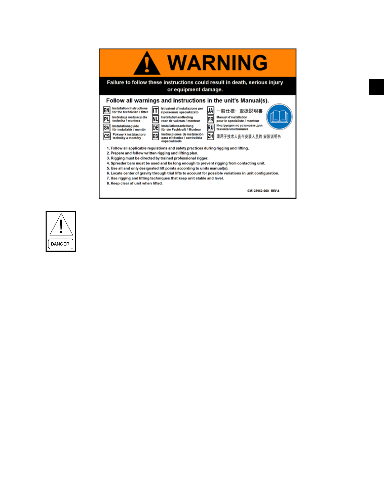
FORM QTC4-NM1
ISSUE DATE: 4/2/2018
SECTION 3 - RIGGING, HANDLING AND STORAGE
3
Rigging and lifting should only be done by a professional rigger in accordance with a written rig-
ging and lifting plan. The most appropriate rigging and lifting method will depend on job specic
factors, such as the rigging equipment available and site needs. Therefore, a professional rigger
must determine the rigging and lifting method to be used, and it is beyond the scope of this manual
to specify rigging and lifting details.
LIFTING WEIGHTS
Refer to the unit nameplate for unit shipping weight.
Note that weight may vary depending on unit configuration at the time of lifting. Refer to the Physical
Data tables within this manual for further information
regarding shipping and operating weights.
DELIVERY AND STORAGE
To ensure consistent quality and maximum reliability, all units are tested and inspected before leaving
the factory. Units are shipped completely assembled
and containing refrigerant under pressure. Units are
shipped without export crating unless crating has been
specified on the Sales Order.
If the unit is to be put into storage, prior to installation,
the following precautions should be observed:
• The chiller must be “blocked” so that the base is
not permitted to sag or bow.
• Ensure that all openings, such as water connections, are securely capped.
• Do not store where exposed to high ambient air
temperatures that may exceed relief valve settings.
LD19197
Refer to Long-Term Storage Requirement - Field
Preparation (Form 50.20-NM7).
• The condensers should be covered to protect the
coils and ns from potential damage and corrosion,
particularly where building work is in progress.
• The unit should be stored in a location where there
is minimal activity in order to limit the risk of
accidental physical damage.
• To prevent inadvertent operation of the pressure
relief devices the unit must not be steam cleaned.
• It is recommended that the unit is periodically inspected during storage.
INSPECTION
Remove any transit packing and inspect the unit to ensure that all components have been delivered and that
no damage has occurred during transit. If any damage
is evident, it should be noted on the carrier’s freight bill
and a claim entered in accordance with the instructions
given on the advice note.
Major damage must be reported immediately to your
local Quantech Representative.
QUANTECH
23
Page 24

SECTION 3 - RIGGING, HANDLING AND STORAGE
LOCKING PIN
LUG
FLANGE
LIFTING HOLE
IN BASE FRAME
CORRECT
LOCKING PIN
LUG
LIFTING HOLE
IN BASE FRAME
FLANGE
INCORRECT
LOCKING
PIN
FLANGE
LUG
FORM QTC4-NM1
ISSUE DATE: 4/2/2018
MOVING THE CHILLER
Prior to moving the unit, ensure that the installation
site is suitable for installing the unit and is easily
capable of supporting the weight of the unit and all associated services. Care should be taken to avoid damaging the condenser cooling fins when moving the unit.
The unit must only be lifted by the base
frame using all lift points provided. Never
move the unit on rollers, or lift the unit
using a forklift truck.
UNIT REMOVAL FROM SHIPPING CONTAINER
1. Place a clevis pin into the holes provided at the
end of each base rail on the unit. Attach chains or
nylon straps through the clevis pins and hook onto
a suitable lift truck for pulling the unit out of the
container.
2. Slowly place tension on the chains or straps until
the unit begins to move and then slowly pull the
unit from the container. Be sure to pull straight so
the sides do not scrape the container.
3. Place a lifting xture on the forks of the lift truck
and reattach the chain or strap. Slightly lift the
front of the unit to remove some weight from the
oor of the container. Continue pulling the unit
with an operator on each side to guide the lift
truck operator.
4. Pull the unit until the lifting locations are outside
of the container. Place 4 X 4 blocks of wood under
the base rails of the unit. Gently rest the unit on
the blocks and remove the chains and lift truck.
Rigging and lifting should only be done by
a professional rigger in accordance with a
written rigging and lifting plan. The most
appropriate rigging and lifting method
will depend on job specic factors, such as
the rigging equipment available and site
needs. Therefore, a professional rigger
must determine the rigging and lifting
method to be used, and it is beyond the
scope of this manual to specify rigging
and lifting details.
LIFTING USING SHACKLES
The shackles should be inserted into the respective
holes in the base frame and secured from the inside.
Use spreader bars to avoid lifting chains hitting the
chiller. Various methods of spreader bar arrangements
may be used, keeping in mind the intent is to keep
the unit stable and to keep the chains from hitting the
chiller and causing damage. Never lift the chiller using
a forklift or by hooking to the top rails. Use only the
lifting holes provided. Lifting Instructions are placed
on a label on the chiller and on the shipping bag.
LIFTING USING LUGS
Units are provided with lifting holes in the base frame
which accept the accessory lifting lug set as shown
in the figure below. The lugs (RH and LH) should be
inserted into the respective holes in the base frame and
turned so that the spring loaded pin engages into the
hole and the flanges on the lug lock behind the hole.
The lugs should be attached to the cables/chains using
shackles or safety hooks.
5. Once the unit is completely removed from the
container, follow the professional written rigging
plan to lift the unit.
FIGURE 4 - LIFT LUG TO REMOVE UNIT FROM SHIPPING CONTAINER
24
LD19197a
LD19197b
FIGURE 5 - ACCESSORY LIFTING LUGS
QUANTECH
Page 25

FORM QTC4-NM1
ISSUE DATE: 03/07/2018
SECTION 3 - RIGGING, HANDLING AND STORAGE
THIS PAGE INTENTIONALLY LEFT BLANK
QUANTECH
25
Page 26
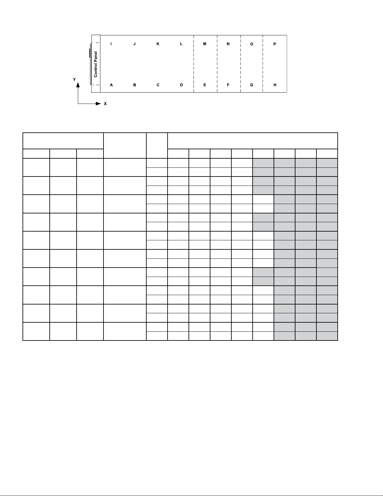
SECTION 3 - RIGGING, HANDLING AND STORAGE
TABLE 1 - UNIT RIGGING
FORM QTC4-NM1
ISSUE DATE: 4/2/2018
LD18582
QTC4 MODEL
DESCRIPTION UNITS
RIGGING HOLES
MODEL COND EVAP A B C D E F G H
150 S B
165 H B
175 P C
185 S A
185 H A
185 P B
175 C C
210 S A
210 H C
210 P C
Rigging Hole
Location
Rigging Hole
Location
Rigging Hole
Location
Rigging Hole
Location
Rigging Hole
Location
Rigging Hole
Location
Rigging Hole
Location
Rigging Hole
Location
Rigging Hole
Location
Rigging Hole
Location
inches 18 60 116 192
mm 464 1512 2937 4866
inches 18 60 137 214
mm 464 1533 3482 5435
inches 12 73 144 197 260
mm 314 1845 3654 5012 6593
inches 18 60 143 220
mm 464 1533 3636 5598
inches 18 60 143 227 272
mm 464 1533 3636 5761 6920
inches 18 60 137 215 302
mm 464 1533 3484 5455 7670
inches 18 60 131 214
mm. 464 1518 3332 5430
inches 18 60 143 227 272
mm 464 1533 3637 5761 6920
inches 12 73 144 197 260
mm 314 1845 3654 5012 6593
inches 12 73 163 254 324
mm 314 1845 4144 6443 8218
NOTE: Rigging and lifting the unit must be done by a professional rigger safely, as discussed in this section. The rigger should locate the center
of gravity through trial lifts to account for possible variations in unit conguration. Contact your nearest Quantech Sales Ofce for weight data.
26
QUANTECH
Page 27
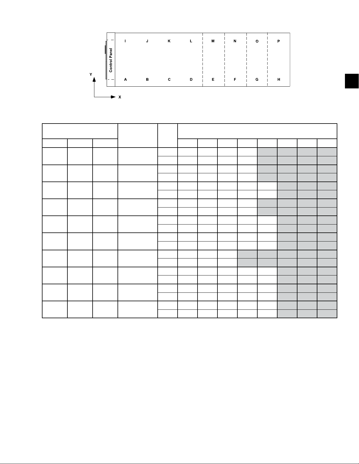
FORM QTC4-NM1
ISSUE DATE: 4/2/2018
TABLE 1 - UNIT RIGGING (CONT'D)
SECTION 3 - RIGGING, HANDLING AND STORAGE
3
LD18582
QTC4 MODEL
DESCRIPTION UNITS
RIGGING HOLES
MODEL COND EVAP I J K L M N O P
150 S B
165 H B
175 P C
185 S A
185 H A
185 P B
175 C C
210 S A
210 H C
210 P C
Rigging Hole
Location
Rigging Hole
Location
Rigging Hole
Location
Rigging Hole
Location
Rigging Hole
Location
Rigging Hole
Location
Rigging Hole
Location
Rigging Hole
Location
Rigging Hole
Location
Rigging Hole
Location
inches 18 60 116 192
mm 464 1511 2937 4866
inches 18 60 137 214
mm 464 1533 3485 5435
inches 12 73 144 197 260
mm 314 1845 3654 5012 6593
inches 18 60 143 220
mm 464 1533 3636 5598
inches 18 60 143 227 272
mm 464 1533 3636 5761 6920
inches 18 60 137 215 302
mm 464 1533 3484 5455 7670
inches 60 131 214
mm 1518 3332 5430
inches 18 60 143 227 272
mm 464 1533 3637 5761 6920
inches 12 73 144 197 260
mm 314 1845 3654 5012 6593
inches 12 73 163 254 324
mm 314 1845 4144 6443 8218
NOTE: Rigging and lifting the unit must be done by a professional rigger safely, as discussed in this section. The rigger should locate the center
of gravity through trial lifts to account for possible variations in unit conguration. Contact your nearest Quantech Sales Ofce for weight data.
QUANTECH
27
Page 28
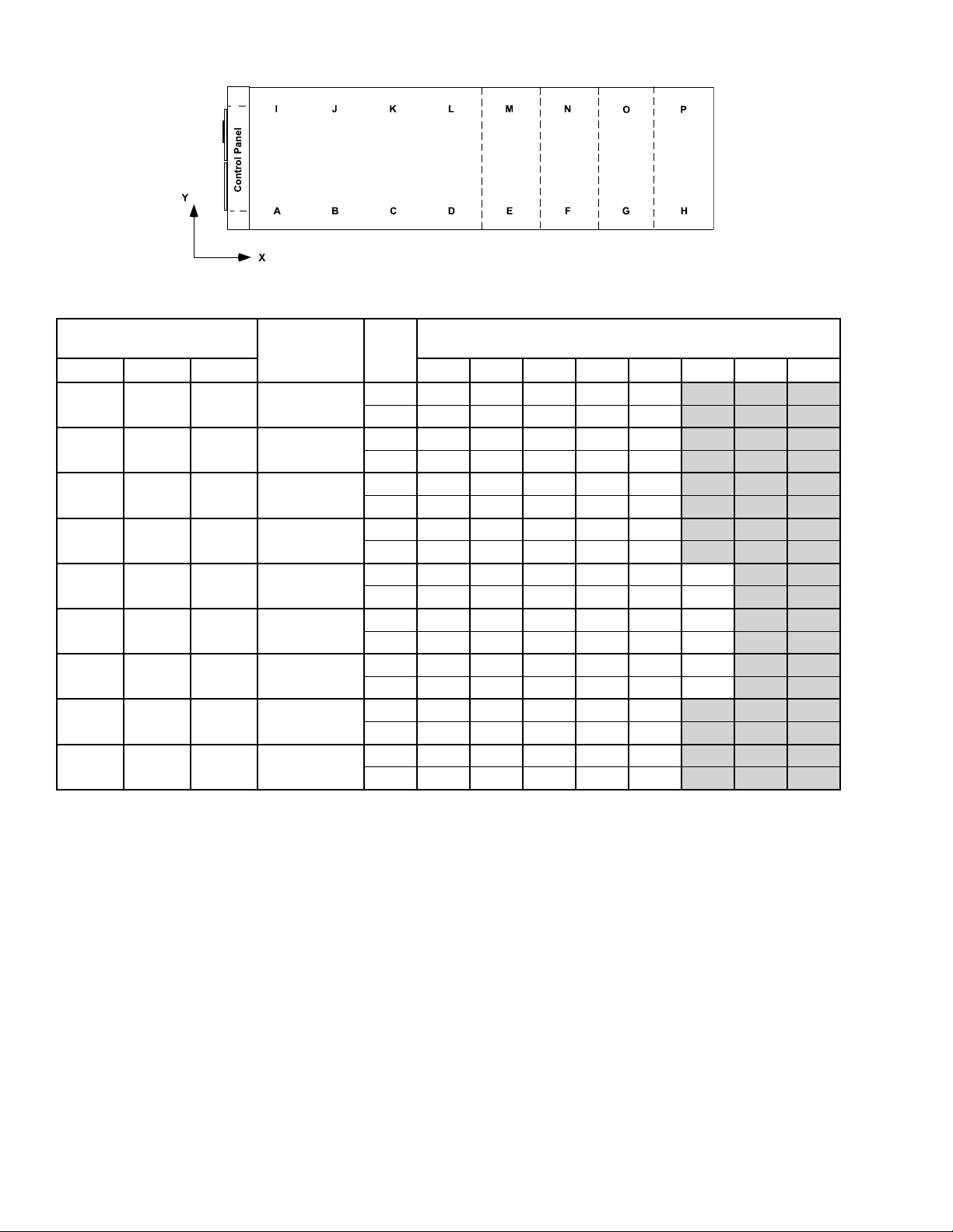
SECTION 3 - RIGGING, HANDLING AND STORAGE
TABLE 1 - UNIT RIGGING (CONT'D)
FORM QTC4-NM1
ISSUE DATE: 4/2/2018
LD18582
QTC4 MODEL
DESCRIPTION UNITS
RIGGING HOLES
MODEL COND EVAP A B C D E F G H
230 S B
240 H C
240 P C
260 S B
270 S D
270 H E
270 P E
290 H E
300 S C
Rigging Hole
Location
Rigging Hole
Location
Rigging Hole
Location
Rigging Hole
Location
Rigging Hole
Location
Rigging Hole
Location
Rigging Hole
Location
Rigging Hole
Location
Rigging Hole
Location
inches 18 60 137 215 272
mm 464 1533 3485 5456 6919
inches 18 60 149 240 324
mm 464 1533 3789 6088 8218
inches 12 73 163 254 347
mm 314 1845 4144 6443 8825
inches 18 60 137 215 302
mm 464 1533 3484 5455 7670
inches 12 73 121 181 264 324
mm 314 1845 3073 4601 6717 8217
inches 12 73 121 181 264 324
mm 314 1845 3073 4601 6717 8218
inches 12 73 121 181 243 347
mm 314 1845 3073 4601 6169 8825
inches 12 73 179 290 347
mm 314 1845 4551 7358 8825
inches 12 73 161 254 347
mm 314 1845 4092 6443 8825
NOTE: Rigging and lifting the unit must be done by a professional rigger safely, as discussed in this section. The rigger should locate the center
of gravity through trial lifts to account for possible variations in unit conguration. Contact your nearest Quantech Sales Ofce for weight data.
28
QUANTECH
Page 29
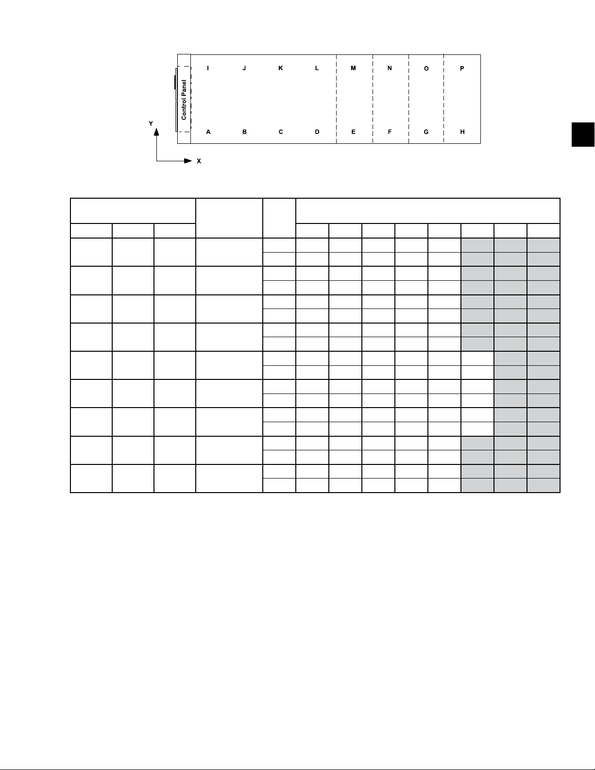
FORM QTC4-NM1
ISSUE DATE: 4/2/2018
TABLE 1 - UNIT RIGGING (CONT'D)
SECTION 3 - RIGGING, HANDLING AND STORAGE
3
LD18582
QTC4 MODEL
DESCRIPTION UNITS
RIGGING HOLES
MODEL COND EVAP I J K L M N O P
230 S B
240 H C
240 P C
260 S B
270 S D
270 H E
270 P E
290 H E
300 S C
Rigging Hole
Location
Rigging Hole
Location
Rigging Hole
Location
Rigging Hole
Location
Rigging Hole
Location
Rigging Hole
Location
Rigging Hole
Location
Rigging Hole
Location
Rigging Hole
Location
inches 18 60 137 215 272
mm 464 1533 3485 5456 6919
inches 18 60 149 240 324
mm 464 1533 3789 6088 8218
inches 12 73 163 254 347
mm 314 1845 4144 6443 8825
inches 18 60 137 215 302
mm 464 1533 3484 5455 7670
inches 12 73 121 181 264 324
mm 314 1845 3073 4601 6717 8218
inches 12 73 121 181 264 324
mm 314 1845 3073 4601 6717 8218
inches 12 73 121 181 243 347
mm 314 1845 3073 4601 6169 8825
inches 12 73 179 290 347
mm 314 1845 4551 7358 8825
inches 12 73 161 254 347
mm 314 1845 4092 6443 8825
NOTE: Rigging and lifting the unit must be done by a professional rigger safely, as discussed in this section. The rigger should locate the center
of gravity through trial lifts to account for possible variations in unit conguration. Contact your nearest Quantech Sales Ofce for weight data.
QUANTECH
29
Page 30
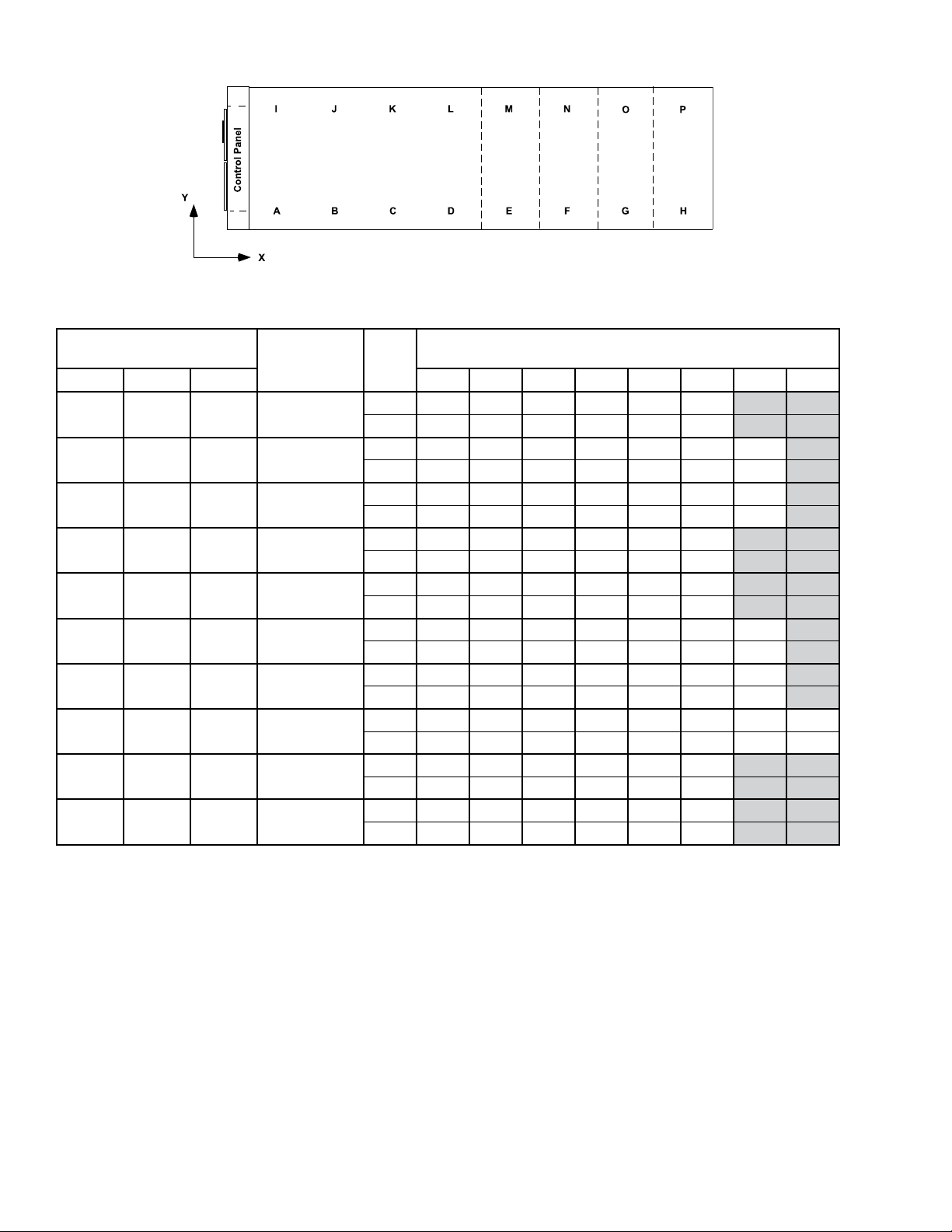
SECTION 3 - RIGGING, HANDLING AND STORAGE
TABLE 1 - UNIT RIGGING (CONT'D)
FORM QTC4-NM1
ISSUE DATE: 4/2/2018
LD18582
QTC4 MODEL
DESCRIPTION UNITS
RIGGING HOLES
MODEL COND EVAP A B C D E F G H
300 H C
310 P E
315 P E
320 S E
330 S C
340 S E
340 H E
370 P J
370 S F
370 H J
Rigging Hole
Location
Rigging Hole
Location
Rigging Hole
Location
Rigging Hole
Location
Rigging Hole
Location
Rigging Hole
Location
Rigging Hole
Location
Rigging Hole
Location
Rigging Hole
Location
Rigging Hole
Location
inches 12 73 161 254 306 391
mm 314 1845 4092 6443 7763 9941
inches 12 73 121 179 243 296 391
mm 314 1845 3072 4549 6169 7508 9942
inches 12 73 121 179 243 353 435
mm 314 1845 3072 4549 6169 8962 11059
inches 12 73 121 181 243 347
mm 314 1845 3073 4601 6169 8825
inches 12 73 163 254 306 391
mm 314 1845 4144 6443 7765 9942
inches 12 73 121 181 243 296 391
mm 314 1845 3073 4602 6170 7511 9942
inches 12 73 121 181 243 353 435
mm 314 1845 3073 4602 6170 8961 11059
inches 12 73 181 238 302 392 434 501
mm 314 1845 4602 6039 7662 9957 11024 12725
inches 12 73 181 238 302 435
mm 314 1845 4602 6039 7662 11059
inches 12 73 181 238 302 435
mm 314 1845 4602 6039 7662 11059
NOTE: Rigging and lifting the unit must be done by a professional rigger safely, as discussed in this section. The rigger should locate the center
of gravity through trial lifts to account for possible variations in unit conguration. Contact your nearest Quantech Sales Ofce for weight data.
30
QUANTECH
Page 31
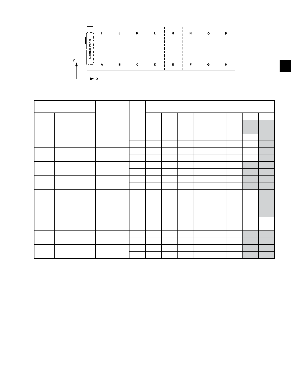
FORM QTC4-NM1
ISSUE DATE: 4/2/2018
TABLE 1 - UNIT RIGGING (CONT'D)
SECTION 3 - RIGGING, HANDLING AND STORAGE
3
LD18582
QTC4 MODEL
DESCRIPTION UNITS
RIGGING HOLES
MODEL COND EVAP I J K L M N O P
300 H C
310 P E
315 P E
320 S E
330 S C
340 S E
340 H E
370 P J
370 S F
370 H J
Rigging Hole
Location
Rigging Hole
Location
Rigging Hole
Location
Rigging Hole
Location
Rigging Hole
Location
Rigging Hole
Location
Rigging Hole
Location
Rigging Hole
Location
Rigging Hole
Location
Rigging Hole
Location
inches 12 73 161 254 306 391
mm 314 1845 4092 6443 7763 9941
inches 12 73 121 179 243 296 391
mm 314 1845 3072 4549 6169 7508 9942
inches 12 73 121 179 243 353 435
mm 314 1845 3072 4549 6169 8962 11059
inches 12 73 121 181 243 347
mm 314 1845 3073 4601 6169 347
inches 12 73 163 254 306 391
mm 314 1845 4144 6443 7765 9942
inches 12 73 121 181 243 296 391
mm 314 1845 3073 4602 6170 7511 9942
inches 12 73 121 181 243 353 435
mm 314 1845 3073 4602 6170 8961 11059
inches 12 73 181 238 302 392 434 501
mm 314 1845 4602 6039 7662 9957 11024 12725
inches 12 73 181 238 302 435
mm 314 1845 4602 6039 7662 11059
inches 12 73 181 238 302 435
mm 314 1845 4602 6039 7662 11059
NOTE: Rigging and lifting the unit must be done by a professional rigger safely, as discussed in this section. The rigger should locate the center
of gravity through trial lifts to account for possible variations in unit conguration. Contact your nearest Quantech Sales Ofce for weight data.
QUANTECH
31
Page 32
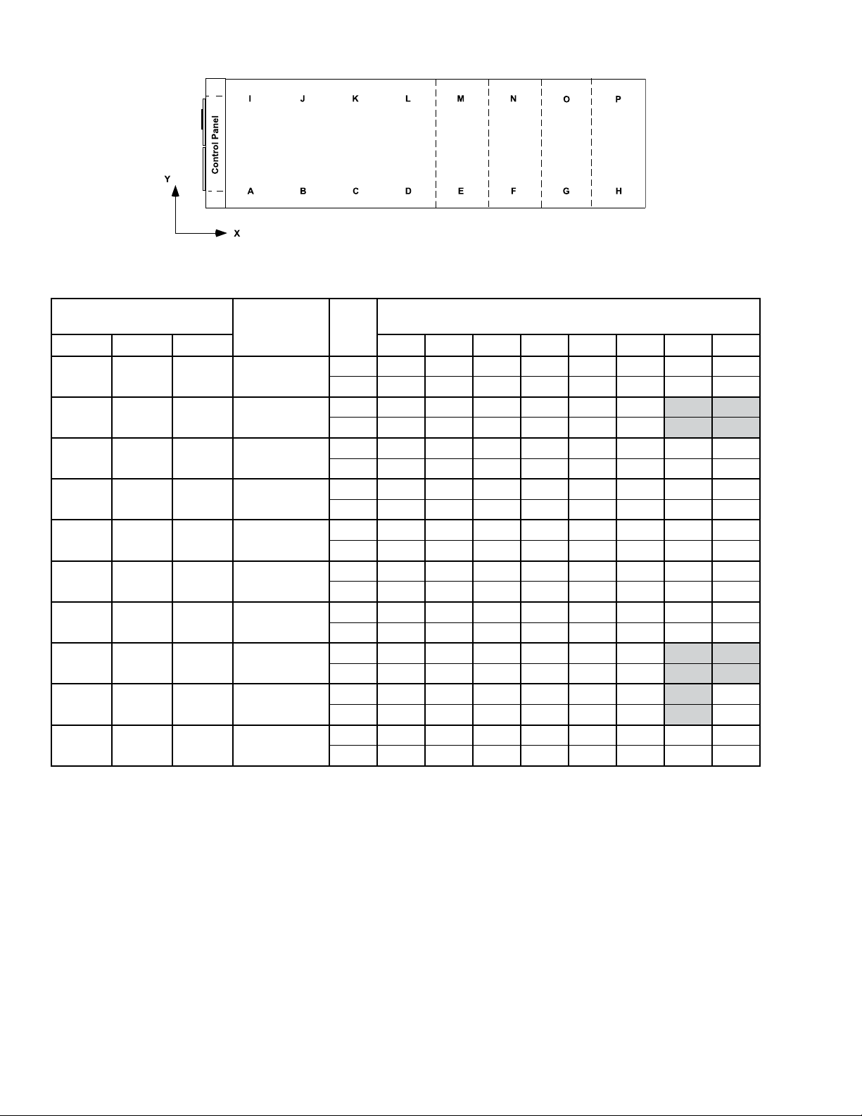
SECTION 3 - RIGGING, HANDLING AND STORAGE
TABLE 1 - UNIT RIGGING (CONT'D)
FORM QTC4-NM1
ISSUE DATE: 4/2/2018
LD18582
QTC4 MODEL
DESCRIPTION UNITS
RIGGING HOLES
MODEL COND EVAP A B C D E F G H
400 P J
405 S H
410 H H
410 P J
450 S G
490 H J
460 S G
470 C K
480 C J
500 S J
Rigging Hole
Location
Rigging Hole
Location
Rigging Hole
Location
Rigging Hole
Location
Rigging Hole
Location
Rigging Hole
Location
Rigging Hole
Location
Rigging Hole
Location
Rigging Hole
Location
Rigging Hole
Location
inches 12 73 181 238 302 435 478 545
mm 314 1845 4602 6039 7358 11059 12135 13835
inches 12 73 181 238 302 435
mm 314 1845 4601 6039 7662 11059
inches 12 73 181 238 302 435 478 545
mm 314 1845 4602 6039 7358 11059 12135 13835
inches 12 73 181 238 302 435 494 572
mm 314 1845 4602 6039 7358 11059 12546 14541
inches 12 73 181 238 290 435 478 545
mm 314 1845 4602 6039 7662 11059 12135 13835
inches 12 73 181 238 290 435 494 572
mm 314 1845 4602 6039 7358 11059 12546 14541
inches 12 73 181 238 290 435 494 572
mm 314 1845 4602 6039 7358 11059 12546 14529
inches 12 73 181 238 290 435
mm 305 1854 4597 6045 7366 11049
inches 12 73 181 238 290 435 572
mm 305 1854 4597 6045 7366 11049 14529
inches 12 73 181 238 290 435 494 572
mm 305 1854 4597 6045 7366 11049 12548 14529
NOTE: Rigging and lifting the unit must be done by a professional rigger safely, as discussed in this section. The rigger should locate the center
of gravity through trial lifts to account for possible variations in unit conguration. Contact your nearest Quantech Sales Ofce for weight data.
32
QUANTECH
Page 33
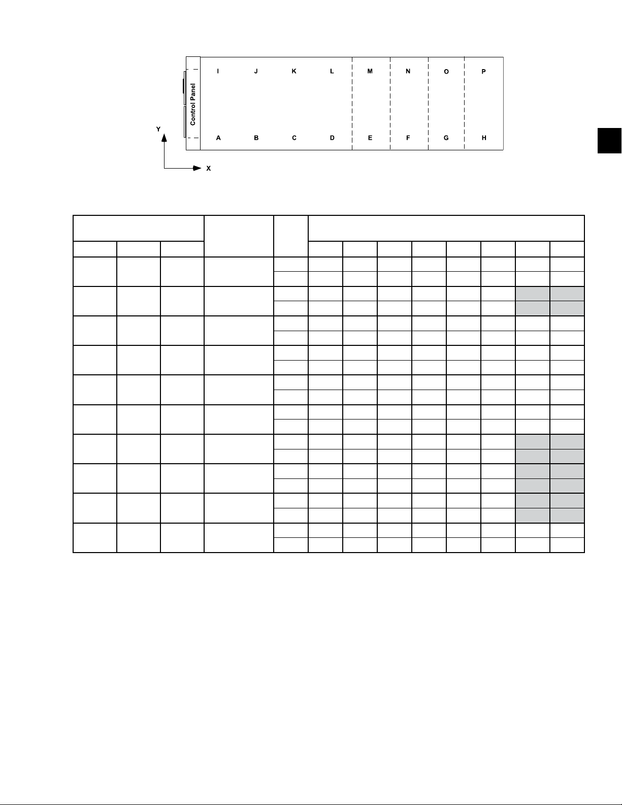
FORM QTC4-NM1
ISSUE DATE: 4/2/2018
TABLE 1 - UNIT RIGGING (CONT'D)
SECTION 3 - RIGGING, HANDLING AND STORAGE
3
LD18582
QTC4 MODEL
DESCRIPTION UNITS
RIGGING HOLES
MODEL COND EVAP I J K L M N O P
400 P J
405 S H
410 H H
410 P J
450 S G
490 H J
460 S G
470 C K
480 C J
500 S J
Rigging Hole
Location
Rigging Hole
Location
Rigging Hole
Location
Rigging Hole
Location
Rigging Hole
Location
Rigging Hole
Location
Rigging Hole
Location
Rigging Hole
Location
Rigging Hole
Location
Rigging Hole
Location
inches 12 73 181 238 302 435 478 545
mm 314 1845 4602 6039 7358 11059 12135 13835
inches 12 73 181 238 302 435
mm 314 1845 4601 6039 7662 11059
inches 12 73 181 238 302 435 478 545
mm 314 1845 4602 6039 7358 11059 12135 13835
inches 12 73 181 238 302 435 494 572
mm 314 1845 4602 6039 7358 11059 12546 14541
inches 12 73 181 238 290 435 478 545
mm 314 1845 4602 6039 7358 11059 12135 13835
inches 12 73 181 238 290 435 494 572
mm 314 1845 4602 6039 7358 11059 12546 14541
inches 12 73 181 238 290 435
mm 305 1854 4597 6045 7366 11049
inches 12 73 181 238 290 435
mm 305 1854 4597 6045 7366 11049
inches 12 73 181 238 290 435
mm 305 1854 4597 6045 7366 11049
inches 12 73 181 238 290 435 494 572
mm 305 1854 4597 6045 7366 11049 12548 14529
NOTE: Rigging and lifting the unit must be done by a professional rigger safely, as discussed in this section. The rigger should locate the center
of gravity through trial lifts to account for possible variations in unit conguration. Contact your nearest Quantech Sales Ofce for weight data.
QUANTECH
33
Page 34

FORM QTC4-NM1
ISSUE DATE: 03/07/2018
THIS PAGE INTENTIONALLY LEFT BLANK
34
QUANTECH
Page 35

FORM QTC4-NM1
ISSUE DATE: 4/2/2018
SECTION 4 - INSTALLATION
LOCATION REQUIREMENTS
For optimum performance and trouble-free service, it
is essential that the installation site meets the location
and space requirements for the model being installed.
Ensure to preserve minimum service access space for
cleaning and maintenance purposes.
OUTDOOR INSTALLATIONS
The units are designed for outdoor installation and
can be installed at ground level on a suitable flat level
foundation easily capable of supporting the weight of
the unit, or on a suitable rooftop location. In both cases
an adequate supply of air is required. Avoid locations
where the sound output and air discharge from the unit
may be objectionable.
The selected location must have minimum sun
exposure and must be away from boiler flues and
other sources of airborne chemicals that could attack
the condenser coils and steel parts of the unit.
If located in an area accessible to unauthorized
persons, steps must be taken to prevent access to the
unit by means of a protective fence. This will help
to prevent the possibility of vandalism, accidental
damage, or possible harm caused by unauthorized
removal of protective guards or opening panels to
expose rotating or high voltage components.
For ground level locations, the unit must be installed
on a suitable flat and level concrete base that extends
to fully support the two side channels of the unit
base frame. A one-piece concrete slab, with footings
extending below the frost line is recommended. To
avoid noise and vibration transmission, the unit should
not be secured to the building foundation.
On rooftop locations, choose a place with adequate
structural strength to safely support the entire operating
weight of the unit and service personnel. The unit can
be mounted on a concrete slab, similar to ground floor
locations, or on steel channels of suitable strength. The
channels should be spaced with the same centers as the
unit side and front base rails. This will allow vibration
isolators to be fitted if required. Isolators are recommended for rooftop locations.
Mounting holes (5/8”) are provided in the base rails for
bolting the unit to its foundation. Refer to Table 10 on
Page 78 for location of the mounting holes.
Any ductwork or attenuators fitted to the unit must
not have a total static pressure resistance, at full unit
airflow, exceeding the capability of the fans installed
in the unit.
The condenser fans are propeller-type and are not
recommended for use with ductwork, filters or other
impediments to airflow in the condenser air stream.
When it is desirable to surround the unit(s) in
addition to whatever optional louver package is
selected, it is recommended that the screening be able
to pass the required chiller CFM without exceeding
0.1"w.g. (24.9084 pa) external static pressure.
Protection against corrosive environments is
available by ordering the units with cured epoxy-coating on the microchannel condenser coil. Epoxy-coated
coils should be used with any units being installed at
the seashore where salt spray / mist may hit the units,
or where acid rain is prevalent.
On installations where winter operation is intended and
snow accumulations are expected, additional elevation
must be provided to insure normal condenser air flow.
Avoid locations near windows or structures where
normal operating sounds may be objectionable.
LOCATION CLEARANCES
Adequate clearances around the unit(s) are required for
the unrestricted airflow for the air-cooled condenser
coils and to prevent re-circulation of warm discharge
air back onto the coils. If clearances given are not
maintained, airflow restriction or re-circulation will
cause a loss of unit performance, an increase in power
consumption, and may cause the unit to malfunction.
Consideration should also be given to the possibility of
down drafts, caused by adjacent buildings, which may
cause re-circulation or uneven unit airflow.
For locations where significant cross winds are
expected, such as exposed roof tops, an enclosure of
solid or louver type is recommended to prevent wind
turbulence interfering with the unit airflow.
When units are installed in an enclosure, the enclosure height should not exceed the height of the unit
on more than one side. If the enclosure is of louvered
construction, the same requirement of static pressure loss
applies as for ducts and attenuators stated above.
4
QUANTECH
35
Page 36
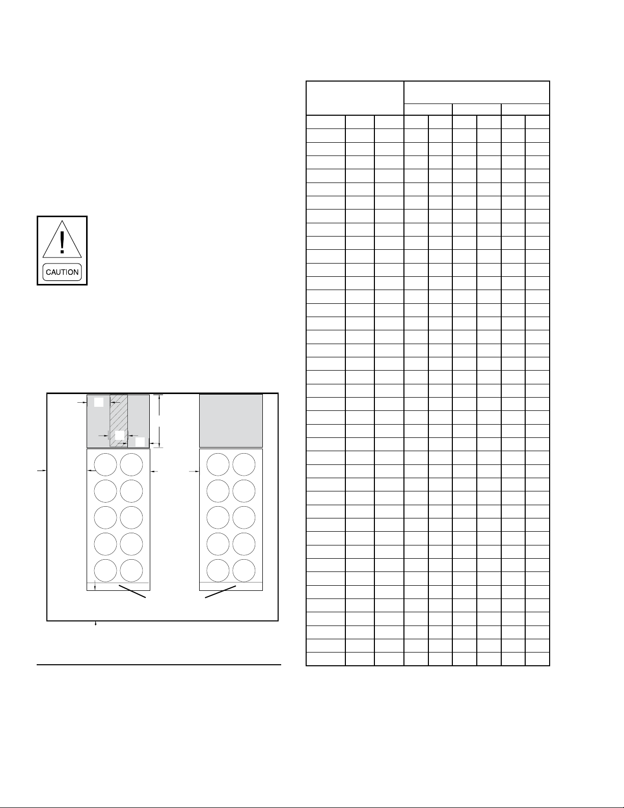
SECTION 4 - INSTALLATION
FORM QTC4-NM1
ISSUE DATE: 4/2/2018
Recommended Minimum Clearances
Recommended clearances for the QTC4 units are:
• Side to wall – 6' (1.8 m)
• Rear to wall – 6' (1.8 m)
• Control panel end to wall – 4' (1.2 m)
• Top – no obstructions whatsoever
• Distance between adjacent units – 10' (3 m)
Clearance dimensions provided in Figure
6 on page 36below and Table 2 on Page
36, are necessary to maintain good
airow and ensure correct unit operation.
It is also necessary to consider access
requirements for safe operation and
maintenance of the unit and power and
control panels. Local health and safety
regulations, or practical considerations
for service replacement of large components, may require larger clearances than
those recommended.
A
Tube Removal
Clearance Area
B
1.8 m (6')
Minimum
1.2 m (4')
Minimum
C
A
3 m (10')
Minimum
Control Panel
FIGURE 6 - ACCEPTABLE MINIMUM CLEARANCES AROUND / BETWEEN UNIT(S)
Tube Removal
Clearance Area
TABLE 2 - MINIMUM EVAPORATOR TUBE REMOVAL CLEARANCE
TUBE REMOVAL
MODEL QTC4
FRAME COND EVAP IN. MM IN. MM IN. MM
150 S B 26 663 36 914 132 3353
165 H B 26 663 36 914 132 3353
175 P C 26 663 36 914 156 3962
185 S A 26 663 36 914 144 3658
185 H A 26 663 36 914 144 3658
185 P B 26 663 36 914 144 3658
175 C C 26 663 36 914 156 3962
210 S A 26 663 36 914 156 3962
210 H C 26 663 36 914 156 3962
210 P C 26 663 36 914 156 3962
230 S B 26 663 36 914 132 3353
240 H C 26 663 36 914 156 3962
240 P C 26 663 36 914 156 3962
260 S B 26 663 36 914 132 3353
270 C D 26 663 36 914 192 4877
270 S D 26 663 36 914 192 4877
270 H E 26 663 36 914 192 4877
270 P E 26 663 36 914 192 4877
290 H E 26 663 36 914 192 4877
300 S C 26 663 36 914 156 3962
300 H E 26 663 36 914 156 3962
310 P E 26 663 36 914 156 3962
315 P E 26 663 36 914 192 4877
320 S E 26 663 36 914 192 4877
330 S C 26 663 36 914 156 3962
340 S E 26 663 36 914 192 4877
340 H E 26 663 36 914 192 4877
370 P J 26 663 36 914 192 4877
370 S F 26 663 36 914 144 3658
370 H J 26 663 36 914 192 4877
400 P J 26 663 36 914 192 4877
405 S H 26 663 36 914 192 4877
410 H H 26 663 36 914 144 3658
410 P J 26 663 36 914 192 4877
450 S G 26 663 36 914 144 3658
490 H J 26 663 36 914 192 4877
460 S G 26 663 36 914 144 3658
470 C K 26 663 36 914 192 4877
480 C J 26 663 36 914 192 4877
500 S J 26 663 36 914 192 4877
CLEARANCE DIMENSIONS
A B C
36
QUANTECH
Page 37

FORM QTC4-NM1
ISSUE DATE: 4/2/2018
SECTION 4 - INSTALLATION
VIBRATION ISOLATORS
Optional sets of vibration isolators can be supplied
loose with each unit.
Using the Isolator tables shipped with the unit in the
information pack. Identify each mount and its correct
location on the unit.
Installation
Place each mount in its correct position and lower the
unit carefully onto the mounts ensuring the mount
engages in the mounting holes in the unit base frame.
On adjustable mounts, transfer the unit weight evenly to the springs by turning the mount adjusting nuts
(located just below the top plate of the mount) counterclockwise to raise and clockwise to lower. This should
be done two turns at a time until the top plates of all
mounts are between 1/4" (6 mm) and 1/2" (12 mm)
clear of top of their housing and the unit base is level.
SHIPPING BRACES
The chiller’s modular design does not require shipping
braces.
CHILLED LIQUID PIPING
General Requirements
The following piping recommendations are intended to
ensure satisfactory operation of the unit(s). Failure to
follow these recommendations could cause damage to
the unit, or loss of performance, and may invalidate the
warranty.
The maximum ow rate and pressure drop
for the evaporator must not be exceeded at
any time. Refer to SECTION 5 - TECHNICAL DATE on page 57 for details.
The Maximum acceptable Chilled Liquid
pressure in the inlet of Evaporator is same
as the statement in "Maximum Tube Side
Pressure" of Pressure Vessel Name Plate
for QTC4 with Falling Film Evaporator.
There should be a straight run of piping of at least 5
pipe diameters on either side. The flow switch should
be wired to Terminals 2 and 13 on the 1TB terminal
block. A flow switch is required to prevent damage to
the evaporator caused by the unit operating without adequate liquid flow.
The flow switch used must have gold plated contacts
for low voltage/current operation. Paddle type flow
switches suitable for 10 barg (150 PSIG) working pressure and having a 1" N.P.T. connection can be obtained
from Quantech as an accessory for the unit. Alternatively, a differential pressure switch fitted across an
orifice plate may be used, preferably of the high/low
limit type.
The chilled liquid pump(s) installed in the piping
system(s) should discharge directly into the unit evaporator section of the system. The pump(s) may be controlled by the chiller controls or external to the unit.
Pipework and fittings must be separately supported to
prevent any loading on the evaporator. Flexible connections are recommended which will also minimize
transmission of vibrations to the building. Flexible
connections must be used if the unit is mounted on
anti-vibration mounts, as some movement of the unit
can be expected in normal operation.
Piping and fittings immediately next to the evaporator
should be readily de-mountable to enable cleaning before operation, and to facilitate visual inspection of the
exchanger nozzles.
The evaporator must be protected by a
strainer, preferably of 16 mesh, tted as
close as possible to the liquid inlet connection, and provided with a means of
local isolation.
The evaporator must not be exposed to flushing
velocities or debris released during flushing. It is
recommended that a suitably sized bypass and valve
arrangement is installed to allow flushing of the piping
system. The bypass can be used during maintenance to
isolate the heat exchanger without disrupting flow to
other units.
4
QUANTECH
The liquid must enter evaporator at the
inlet connection. The standard inlet connection is opposite the control panel end
of the evaporator. A ow switch must be
installed in the customer piping at the
outlet of the evaporator and wired back
to the control panel using shielded cable.
Thermometer and pressure gauge connections should
be provided on the inlet and outlet connections of each
evaporator. Gauges and thermometers are not provided
with the unit and are to be furnished by others.
Drain and air vent connections should be provided at
all low and high points in the piping to permit drainage
of the system and to vent any air in the pipes.
37
Page 38
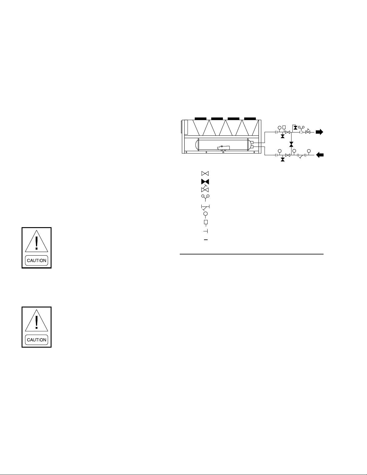
SECTION 4 - INSTALLATION
FORM QTC4-NM1
ISSUE DATE: 4/2/2018
Liquid system lines at risk of freezing, due to low ambient temperatures should be protected using insulation and heater tape and/or a suitable glycol solution.
The liquid pump(s) may also be used to ensure liquid
is circulated when the ambient temperature approaches
freezing point.
Insulation should also be installed around the evaporator nozzles. Heater tape of 21 Watts per meter under
the insulation is recommended, supplied independently
and controlled by an ambient temperature thermostat
set to switch ON at approximately 2.2°C (4°F), above
the freezing temperature of the chilled liquid.
Evaporator heater mats are installed under the insulation, and are powered from the chiller's control panel.
In sub-freezing conditions, unless the evaporator has
been drained or an appropriate water-to-glycol concentration is maintained, high voltage power to the chiller must be kept on to ensure the heater mats assist in
evaporator freeze protection. If there is a potential for
power loss, Quantech recommends that the evaporator
is drained or that water in the chilled water circuit be
replaced with an appropriate water-to-glycol concentration.
Any debris left in the water piping between the strainer and evaporator could
cause serious damage to the tubes in the
evaporator and must be avoided. Be sure
the piping is clean before connecting it to
the evaporator. Keep evaporator nozzles
and chilled liquid piping capped prior to
installation to assure construction debris
is not allowed to enter.
The installer/user must also ensure that
the quality of the water in circulation is
adequate, without any dissolved gases,
which can cause oxidation of steel or copper parts within the evaporator.
WATER TREATMENT
The unit performance provided in the Design Guide is
based on a fouling factor of 0.018m2/hr °C/kW (0.0001
ft2hr°F/Btu). Dirt, scale, grease and certain types of water treatment will adversely affect the heat exchanger
surfaces and therefore the unit performance. Foreign
matter in the water system(s) can increase the heat exchanger pressure drop, reducing the flow rate and causing potential damage to the heat exchanger tubes. Aerated, brackish or salt water is not recommended for use
in the water system(s).
Quantech recommends that a water treatment specialist
should be consulted to determine whether the proposed
water composition will adversely affect the evaporator
materials of carbon steel and copper. The pH value of
the water flowing through the evaporator must be kept
in a range between 7 and 8.5.
PIPEWORK ARRANGEMENT
The following is a suggested piping arrangement for
single unit installations.
-Isolating Valve - Normally Open
-Isolating Valve - Normally Closed
-Flow Regulating Valve
-Flow Measurement Device
-Strainer
-Pressure Tapping
-Flow Switch
-Flanged Connection
-Pipework
FIGURE 7 - PIPEWORK ARRANGEMENT
LD15151
MINIMUM WATER VOLUME
It is good practice to include as much water volume as
possible in a chilled water loop. This increases the thermal mass and “Flywheel” effect within the system (that
is: the more; the better) which in turn promotes stable
water temperature control and increases reliability by
reducing compressor cycling.
For air conditioning applications, a minimum of 3 gallons/ton is required. It is preferred that the gallon/ton
ratio be within the 5 to 8 range. For process applications, a minimum of 6 gallons/ton ratio is required with
preference towards a range of 7 to 11. Install a tank or
increase pipe sizes to provide sufficient water volume.
LEAVING WATER TEMPERATURE OUT OF RANGE
The QTC4 chiller line has a maximum leaving water
temperature of 15.6°C (60°F). Where process applications require a chilled water temperature higher than
what the chiller provides, a simple piping change can
remove the problem. By using a mixture of chillercooled water and returning process water, the chilled
38
QUANTECH
Page 39
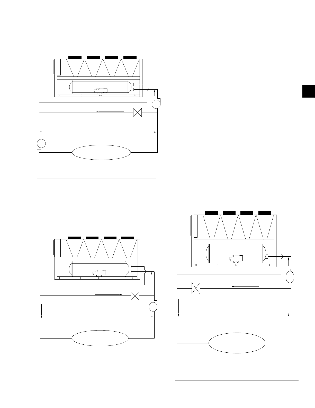
FORM QTC4-NM1
ISSUE DATE: 4/2/2018
SECTION 4 - INSTALLATION
water entering the process can be held at the desired
temperature. A tank can also be used to meet high leaving water temperature requirements.
RECIRCULATION
SUPPLY TO LOAD
RETURN FROM LOAD
LOAD
LD15049
FIGURE 8 - LEAVING WATER TEMPERATURE OUT
OF RANGE SUGGESTED LAYOUT
FLOW RATE OUT OF RANGE
Each QTC4 evaporator has a minimum and maximum
flow rate. Some process applications require a flow
rate that is out of range for the evaporator. In those applications, a piping change can remove the problem.
In applications where the required flow rate is less than
the evaporator’s minimum allowable, the chilled water
can be recirculated to the chiller.
In applications where the required flow rate is greater
than the evaporator’s maximum allowable, the chilled
water can be recirculated to the load.
THERMAL STORAGE
Thermal storage is the practice of storing cooling energy during a period of little or no load and/or low energy
costs for use during periods of high load and/or energy
costs. Conventional cooling systems produce cooling
when it is needed which is commonly during times of
peak demand. Thermal storage allows generation of
cooling capacity to occur during off-peak periods and
store that capacity to meet future cooling requirements.
Using thermal storage can result in smaller equipment
sizes, thereby reducing capital cost, and also can result
in significant energy cost savings
The QTC4 has special control logic to be able to produce chilled leaving brine temperatures below 4.4°C
(40°F) so as to supply a storage tank with chilled liquid during times of low demand. QTC4 chillers selected
for thermal storage operation can also be selected to
efficiently provide chilled fluid at nominal cooling loads.
4
BYPASS
SUPPLY TO LOAD
RETURN FROM LOAD
LOAD
LD15050
FIGURE 9 - SUGGESTED LAYOUT FOR APPLICATIONS WITH FLOW RATES LESS THAN THE EVAPORATOR MINIMUM ALLOWABLE FLOW RATE
QUANTECH
BYPASS
SUPPLY TO LOAD
LOAD
LD15051
FIGURE 10 - SUGGESTED LAYOUT FOR APPLICATIONS WITH A FLOW RATE GREATER THAN THE EVAPORATOR MAXIMUM ALLOWABLE FLOW RATE
39
Page 40

SECTION 4 - INSTALLATION
FORM QTC4-NM1
ISSUE DATE: 4/2/2018
VARIABLE PRIMARY FLOW
Quantech recommends a maximum 10% per minute
flow rate of change, based on design flow, for variable
primary flow applications. Provide 8 to 10 gallons per
chiller ton (8.6 to 10.8 liter per cooling KW) system water volume. Insufficient system volume and rapid flow
changes can cause control problems or can even cause
chiller shutdowns. There are many other design issues
to evaluate with variable primary flow systems. Consult
your Quantech Sales Representative for more information about successfully applying QTC4 chillers.
CONNECTION TYPES AND SIZES
For connection sizes relevant to individual models, refer to SECTION 5 - TECHNICAL DATA.
EVAPORATOR CONNECTIONS
Standard chilled liquid connections on evaporators are
of the Victaulic Groove type.
LD10494
FIGURE 11 - VICTAULIC GROOVE
TABLE 3 - EVAPORATOR CONNECTIONS DIMEN-
SIONS
VICTAULIC
FRAME COND. EVAP.
150 S B 6" DN150
165 H B 6" DN150
175 P C 6" DN150
185 S A 6" DN150
185 H A 6" DN150
185 P B 6" DN150
175 C C 6" DN150
210 S A 6" DN150
210 H C 6" DN150
210 P C 6" DN150
230 S B 6" DN150
240 H C 6" DN150
240 P C 6" DN150
260 S B 6" DN150
270 C D 6" DN150
270 S D 6" DN150
270 H E 8" DN200
270 P E 8" DN200
290 H E 8" DN200
300 S C 6" DN150
300 H C 6" DN150
310 P E 8" DN200
315 P E 8" DN200
320 S E 8" DN200
330 S C 6" DN150
340 S E 8" DN200
340 H E 8" DN200
370 P J 8" DN200
370 S F 8" DN200
370 H J 8" DN200
400 P J 8" DN200
405 S H 8" DN200
410 H H 8" DN200
410 P J 8" DN200
450 S G 8" DN200
490 H J 8" DN200
460 S G 8" DN200
470 C K 8" DN200
480 C J 8" DN200
500 S J 8" DN200
* Reference Figure 12 on Page 41 for ange dimensions.
CONNECTIONS
SIZE
NOMINAL
DIAMETER
40
QUANTECH
Page 41
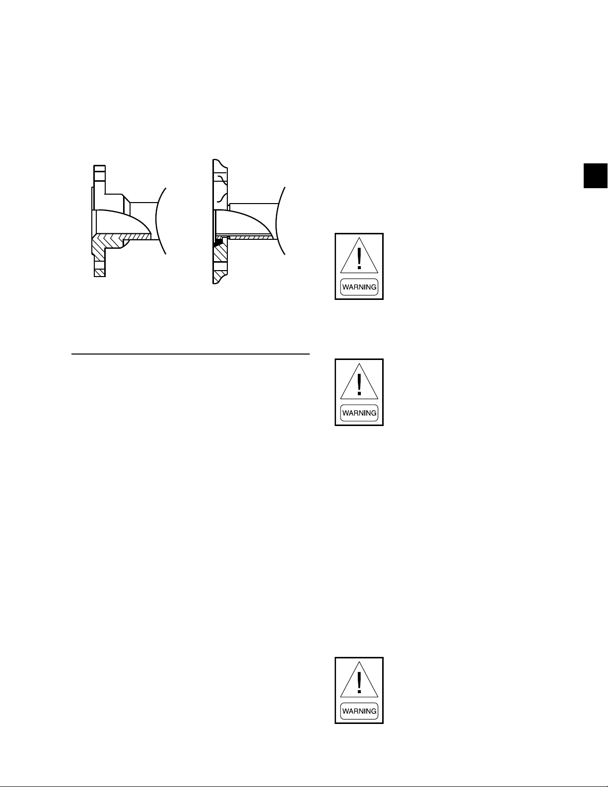
FORM QTC4-NM1
ISSUE DATE: 4/2/2018
SECTION 4 - INSTALLATION
Option Flanges
One of two types of flanges may be fitted depending
on the customer or local pressure vessel code requirements. These are Victaulic-Adapter flanges, normally
supplied loose, or weld flanges, which may be supplied loose or ready-fitted. Victaulic-Adapter and weld
flange dimensions are to ISO 7005 - NP10.
WELD FLANGE VICTAULIC ADAPTER
LD10495
FIGURE 12 - FLANGE ATTACHMENT
If relief piping is common to more than one valve, its
cross-sectional area must be at least the total required
by each valve. Valve types should not be mixed on a
common pipe. Precautions should be taken to ensure
the outlets of relief valves or relief valve vent pipes
remain clear of obstructions at all times.
ELECTRICAL CONNECTION
The following connection recommendations are
intended to ensure safe and satisfactory operation of
the unit. Failure to follow these recommendations
could cause harm to persons or damage the unit, and
may invalidate the warranty.
No additional controls (relays, etc.)
should be mounted in the control panel.
Power and control wiring not connected
to the control panel should not be run
through the control panel. If these precautions are not followed it could lead to
a risk of electrocution. In addition, electrical noise could cause malfunctions or
damage the unit and its controls.
4
REFRIGERANT RELIEF VALVE PIPING
The evaporator is protected against internal refrigerant
overpressure by refrigerant relief valves. A pressure
relief valve is mounted on each of the main refrigerant
lines connecting the evaporator to the compressors.
A piece of pipe is fitted to each valve and directed so
that when the valve is activated the release of high
pressure gas and liquid cannot be a danger or cause
injury. For indoor installations (not recommended),
pressure relief valves should be piped to the exterior
of the building.
The size of any piping attached to a relief valve must
be of sufficient diameter so as not to cause resistance to
the operation of the valve. Unless otherwise specified
by local regulations. Internal diameter depends on the
length of pipe required and is given by the following
formula:
D5 = 1.447 x L
Where:
• D = minimum pipe internal diameter in cm
• L = length of pipe in meters
After power wiring connection, do not
switch on mains power to the unit. Some
internal components are live when the
mains are switched on and this must
only be done by “Authorized” persons
familiar with starting, operating, and
troubleshooting this type of equipment.
POWER WIRING
All electrical wiring should be carried out in accordance with local regulations. Route properly sized
cables to cable entries on the unit.
In accordance with local codes, NEC codes, U.L. and
C.E. standards, it is the responsibility of the user to
install over current protection devices between the
supply conductors and the power supply terminals on
the unit.
To ensure that no eddy currents are set up in the power
panel, the cables forming the 3-phase power supply
must enter via the same cable entry.
All sources of supply to the unit must be
taken via a common point of isolation
(not supplied by Quantech).
QUANTECH
41
Page 42
SECTION 4 - INSTALLATION
FORM QTC4-NM1
ISSUE DATE: 4/2/2018
Copper power wiring only should be used for supplying power to the chiller. This is recommended to avoid
safety and reliability issues resulting from connection
failure at the power connections to the chiller. Aluminum wiring is not recommended due to thermal characteristics that may cause loose terminations resulting from the contraction and expansion of the wiring.
Aluminum oxide may also build up at the termination
causing hot spots and eventual failure. If aluminum
wiring is used to supply power to the chiller, AL-CU
compression fittings should be used to transition from
aluminum to copper. This transition should be done in
an external box separate to the power panel. Copper
conductors can then be run from the box to the chiller.
Caulk power and control wiring conduit
entering the power panel to assure moist
air from the building cannot enter the
panel.
POWER SUPPLY WIRING
Units require only one 3-phase supply, plus earth.
Connect the 3-phase supplies to the circuit breaker
located in the panel (See Table 4 on Page 47).
Connect a suitably sized earth wire to the PE terminal
in the panel.
CONTROL WIRING
All control wiring utilizing contact closures to the control panel terminal block is nominal 115VAC and must
be run in shielded cable, with the shield grounded at
the panel end only, and run in water tight conduit. Run
shielded cable separately from mains cable to avoid
electrical noise pick-up. Use the control panel cable
entry to avoid the power cables.
Voltage free contacts connected to the panel must be
suitable for 115VAC10 ma (gold contacts recommended). If the voltage free contacts form part of a relay or
contactor, the coil of the device must be suppressed using
a standard R/C suppressor. The above precautions must
be taken to avoid electrical noise, which could cause a
malfunction or damage to the unit and its controls.
VOLTS FREE CONTACTS
Chilled Liquid Pump Starter
Terminals 23 and 24 on 1TB close to start the chilled
liquid pump. This contact can be used as a master start/
stop for the pump in conjunction with the daily start/
stop schedule. Cycle the pumps from the unit panel if
the unit will be operational or shut-down during subfreezing conditions. Refer to the Evaporator Pump
Control on Page 96 for more information on testing
the pumps.
115VAC CONTROL SUPPLY TRANSFORMER
A 3-wire high voltage to 115VAC supply transformer
is standard in the chiller. This transformer is mounted
in the cabinet and steps down the high voltage supply
to 115VAC to be used by the Controls, VSD, Feed and
Drain Valve Controller, Valves, Solenoids, Heaters, etc.
The high voltage for the transformer primary is
taken from the chiller input. Fusing is provided for the
transformer.
Removing high voltage power to the
chiller will remove the 115VAC supply
voltage to the control panel circuitry
and the evaporator heater mat. In subfreezing weather, this could cause serious
damage to the chiller due to evaporator
freeze-up. Do not remove power unless
alternate means are taken to ensure operation of the control panel, evaporator
heater mat, and waterbox heaters.
Run Contact
Terminals 21 and 22 on 1TB close to indicate that a
system is running.
Alarm Contacts
Each system has a single voltage-free contact, which
will operate to signal an alarm condition whenever any
system locks out, or there is a power failure. To obtain
system alarm signal, connect the alarm circuit to volt
free Terminals 25 & 26 (Sys 1), Terminals 27 and 28
(Sys 2) of 1TB.
SYSTEM INPUTS
Flow Switch
A chilled liquid flow switch of suitable type MUST be
connected between Terminals 2 and 13 of 1TB to provide protection against loss of liquid flow, which will
cause evaporator freeze-up if the chiller is permitted
to run. The flow switch circuitry is a 115VAC circuit.
Contacts must be rated for low current (5mA). Gold
contacts should be used.
42
QUANTECH
Page 43

FORM QTC4-NM1
ISSUE DATE: 4/2/2018
SECTION 4 - INSTALLATION
Remote Run / Stop
A Remote Run/Stop input is available for each systems.
These inputs require a dry contact to start and stop the
system. System 1 remote dry contacts are connected
between Terminals 2 and 15 of 1TB and System 2 dry
contacts are connected between Terminals 2 and 16 of
1TB. If remote start/stop is not utilized, a jumper must
be paced across the terminals to allow the system to
run. The remote run/stop circuitry is a 115VAC circuit.
Contacts must be rated for low current (5mA). Gold
contacts should be used.
Remote Print
Closure of suitable contacts connected to Terminals
2 and 14 of 1TB will cause a hard copy printout of
Operating Data/Fault History to be made if an optional
printer is connected to the RS-232 port. The remote print
circuitry is a 115VAC circuit. Contacts must be rated for
low current (5mA). Gold contacts should be used.
Optional Remote Setpoint Offset – Temperature
A voltage signal connected to Terminals 17 and 18 of
1TB will provide a remote offset function of the chilled
liquid setpoint, if required.
Optional Remote Setpoint Offset – Current
A voltage signal connected to Terminals 19 and 20
of 1TB will provide a remote setting of current limit
setpoint, if required.
Optional Remote Setpoint Offset – Sound Limiting
A voltage signal connected to Terminals 40 and 41 of
1TB will provide remote setting of sound limit setpoint,
if required.
4
QUANTECH
43
Page 44

SECTION 4 - INSTALLATION
POWER SUPPLY WIRING
FORM QTC4-NM1
ISSUE DATE: 4/2/2018
Single Point Wiring
Minimum Circuit Ampacity (MCA),
Minimum/Maximum Fuse Size and
Minimum/Maximum Circuit Breaker size
varies on chillers based upon model and
options ordered. Consult YorkWorks or
the chiller data plate for electrical data
on a specic chiller.
FIGURE 13 - SINGLE POINT POWER WIRING
44
Voltage Utilization Range
RATED
VOLTAGE
200/60/3 180-220
230/60/3 208-254
380/60/3 342-402
400/60/3 360-440
460/60/3 414-508
575/60/3 520-635
400/50/3 360-440
UTILIZATION RANGE
LD18588
QUANTECH
Page 45
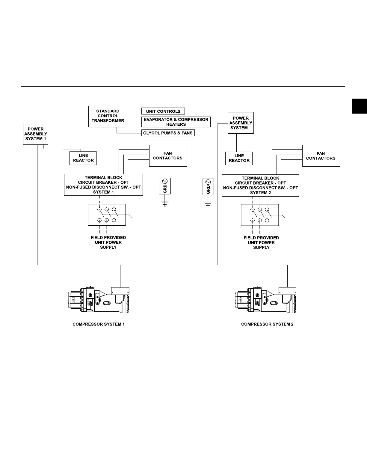
FORM QTC4-NM1
ISSUE DATE: 4/2/2018
SECTION 4 - INSTALLATION
Dual Point Wiring
4
2
FIGURE 14 - DUAL POINT POWER WIRING
QUANTECH
LD18589
45
Page 46
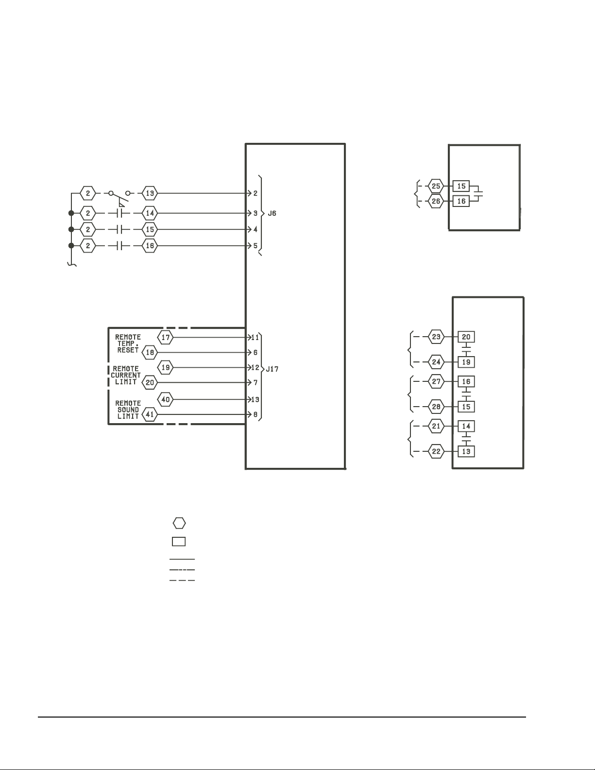
SECTION 4 - INSTALLATION
SYS. No. 1
ALARM
CONTACTS
SYS. No. 2
ALARM
CONTACTS
CHILLER
RUN
EVAP. PUMP
START
SIGNAL
SYS. No. 1 RUN PERM
SYS. No. 2 RUN PERM
FLOW SWITCH (-SF)
PRINT (PNT)
LEGEND
TERMINAL BLOCK FOR CUSTOMER CONNECTIONS
TERMINAL BLOCK FOR QUANTECH CONNECTIONS
WIRING AND COMPONENTS BY QUANTECH
OPTIONAL EQUIPMENT
WIRING AND/OR COMPONENTS BY OTHERS
RELAY
BOARD
No. 2
RELAY
BOARD
No. 1
CONTROL
BOARD
+ SIGNAL INPUT
+ SIGNAL INPUT
+ SIGNAL INPUT
- SIGNAL INPUT (GND)
- SIGNAL INPUT (GND)
- SIGNAL INPUT (GND)
FORM QTC4-NM1
ISSUE DATE: 4/2/2018
CUSTOMER CONTROL WIRING
FIGURE 15 - CUSTOMER CONTROL CONNECTIONS
46
QUANTECH
Page 47
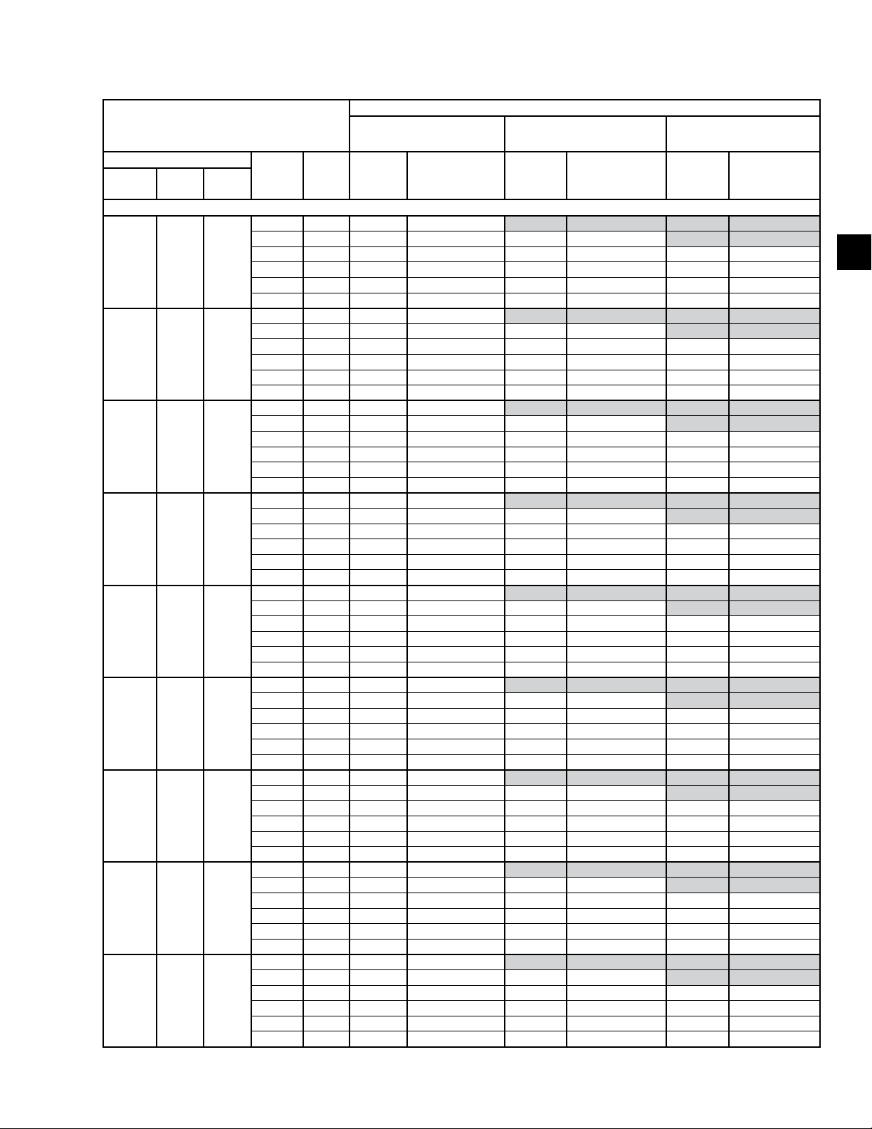
FORM QTC4-NM1
ISSUE DATE: 4/2/2018
TABLE 4 - ELECTRICAL LUG DATA
FIELD WIRING LUGS
QTC4 MODEL
MODEL COND EVAP
150 S B
165 H B
175 P C
185 S A
185 H A
185 P B
175 C C
210 S A
210 H C
INPUT
VOLTS
INPUT
FREQ
200 60 4 #2 - 600 kcmil
230 60 4 #2 - 600 kcmil 4 4/0 ~ 500 kcmil
380 60 2 #2 - 600 kcmil 2 #2/0 ~ 500 kcmil 2 #2 - 600 kcmil
400 50 2 #2 - 600 kcmil 2 #2/0 ~ 500 kcmil 2 #2 - 600 kcmil
460 60 2 #2 - 600 kcmil 2 #1 ~ 500 kcmil 2 #2 - 600 kcmil
575 60 2 #2 - 600 kcmil 2 #1 ~ 500 kcmil 2 #2 ~ 600 kcmil
200 60 4 #2 - 600 kcmil
230 60 4 #2 - 600 kcmil 4 4/0 ~ 500 kcmil
380 60 2 #2 - 600 kcmil 2 #2/0 ~ 500 kcmil 2 #2 - 600 kcmil
400 50 2 #2 - 600 kcmil 2 #2/0 ~ 500 kcmil 2 #2 - 600 kcmil
460 60 2 #2 - 600 kcmil 2 #1 ~ 500 kcmil 2 #2 - 600 kcmil
575 60 2 #2 - 600 kcmil 2 #1 ~ 500 kcmil 2 #2 ~ 600 kcmil
200 60 4 #2 - 600 kcmil
230 60 4 #2 - 600 kcmil 4 4/0 ~ 500 kcmil
380 60 2 #2 - 600 kcmil 2 #2/0 ~ 500 kcmil 2 #2 - 600 kcmil
400 50 2 #2 - 600 kcmil 2 #2/0 ~ 500 kcmil 2 #2 - 600 kcmil
460 60 2 #2 - 600 kcmil 2 #1 ~ 500 kcmil 2 #2 - 600 kcmil
575 60 2 #2 - 600 kcmil 2 #1 ~ 500 kcmil 2 #2 ~ 600 kcmil
200 60 4 #2 - 600 kcmil
230 60 4 #2 - 600 kcmil 4 4/0 ~ 500 kcmil
380 60 2 #2 - 600 kcmil 2 #1 ~ 500 kcmil 3 #2 ~ 600 kcmil
400 50 2 #2 - 600 kcmil 2 #1 ~ 500 kcmil 3 #2 ~ 600 kcmil
460 60 2 #2 - 600 kcmil 2 #1 ~ 500 kcmil 2 #2 - 600 kcmil
575 60 2 #2 - 600 kcmil 2 #1 ~ 500 kcmil 2 #2 ~ 600 kcmil
200 60 4 #2 - 600 kcmil
230 60 4 #2 - 600 kcmil 4 4/0 ~ 500 kcmil
380 60 2 #2 - 600 kcmil 2 #1 ~ 500 kcmil 3 #2 ~ 600 kcmil
400 50 2 #2 - 600 kcmil 2 #1 ~ 500 kcmil 3 #2 ~ 600 kcmil
460 60 2 #2 - 600 kcmil 2 #1 ~ 500 kcmil 2 #2 - 600 kcmil
575 60 2 #2 - 600 kcmil 2 #1 ~ 500 kcmil 2 #2 ~ 600 kcmil
200 60 4 #2 - 600 kcmil
230 60 4 #2 - 600 kcmil 4 4/0 ~ 500 kcmil
380 60 2 #2 - 600 kcmil 2 #1 ~ 500 kcmil 3 #2 ~ 600 kcmil
400 50 2 #2 - 600 kcmil 2 #1 ~ 500 kcmil 3 #2 ~ 600 kcmil
460 60 2 #2 - 600 kcmil 2 #1 ~ 500 kcmil 2 #2 - 600 kcmil
575 60 2 #2 - 600 kcmil 2 #1 ~ 500 kcmil 2 #2 ~ 600 kcmil
200 60 4 #2 - 600 kcmil
230 60 4 #2 - 600 kcmil 4 4/0 ~ 500 kcmil
380 60 3 #2 - 600 kcmil 3 3/0 ~ 400 kcmil 3 #2 ~ 600 kcmil
400 50 3 #2 - 600 kcmil 3 3/0 ~ 400 kcmil 3 #2 ~ 600 kcmil
460 60 2 #2 - 600 kcmil 2 #1 ~ 500 kcmil 3 #2 - 600 kcmil
575 60 2 #2 - 600 kcmil 2 #1 ~ 500 kcmil 2 #2 ~ 600 kcmil
200 60 4 #2 - 600 kcmil
230 60 4 #2 - 600 kcmil 4 4/0 ~ 500 kcmil
380 60 2 #2 - 600 kcmil 2 #1 ~ 500 kcmil 3 #2 ~ 600 kcmil
400 50 2 #2 - 600 kcmil 2 #1 ~ 500 kcmil 3 #2 ~ 600 kcmil
460 60 2 #2 - 600 kcmil 2 #1 ~ 500 kcmil 2 #2 - 600 kcmil
575 60 2 #2 - 600 kcmil 2 #1 ~ 500 kcmil 2 #2 ~ 600 kcmil
200 60 4 #2 - 600 kcmil
230 60 4 #2 - 600 kcmil 4 4/0 ~ 500 kcmil
380 60 2 #2 - 600 kcmil 2 #1 ~ 500 kcmil 3 #2 ~ 600 kcmil
400 50 2 #2 - 600 kcmil 2 #1 ~ 500 kcmil 3 #2 ~ 600 kcmil
460 60 2 #2 - 600 kcmil 2 #1 ~ 500 kcmil 2 #2 - 600 kcmil
575 60 2 #2 - 600 kcmil 2 #1 ~ 500 kcmil 2 #2 ~ 600 kcmil
STANDARD & ULTRA QUIET CONDENSER FANS
TERMINAL
BLOCK
WIRES
PER
PHASE
SINGLE POINT WIRING
LUG
WIRE
RANGE
WIRES
PER
PHASE
CIRCUIT
BREAKER
LUG
WIRE
RANGE
SECTION 4 - INSTALLATION
NON-FUSED
DISCONNECT SWITCH
WIRES
PER
PHASE
LUG
WIRE
RANGE
4
QUANTECH
47
Page 48

SECTION 4 - INSTALLATION
TABLE 4 - ELECTRICAL LUG DATA (CONT'D)
FIELD WIRING LUGS
QTC4 MODEL
MODEL COND EVAP
150 S B
165 H B
175 P C
185 S A
185 H A
185 P B
175 C C
210 S A
210 H C
INPUT
VOLTS
INPUT
FREQ
200 60 4 #1/0 ~ 700 kcmil
230 60 4 #2 - 600 kcmil 4 4/0 ~ 500 kcmil
380 60 2 #2 - 600 kcmil 2 #1 ~ 500 kcmil 3 #2 ~ 600 kcmil
400 50 2 #2 - 600 kcmil 2 #1 ~ 500 kcmil 3 #2 ~ 600 kcmil
460 60 2 #2 - 600 kcmil 2 #1 ~ 500 kcmil 3 #2 ~ 600 kcmil
575 60 2 #2 - 600 kcmil 2 #1 ~ 500 kcmil 2 #2 ~ 600 kcmil
200 60 4 #1/0 ~ 700 kcmil
230 60 4 #2 - 600 kcmil 4 4/0 ~ 500 kcmil
380 60 2 #2 - 600 kcmil 2 #1 ~ 500 kcmil 3 #2 ~ 600 kcmil
400 50 2 #2 - 600 kcmil 2 #1 ~ 500 kcmil 3 #2 ~ 600 kcmil
460 60 2 #2 - 600 kcmil 2 #1 ~ 500 kcmil 3 #2 ~ 600 kcmil
575 60 2 #2 - 600 kcmil 2 #1 ~ 500 kcmil 2 #2 ~ 600 kcmil
200 60 4 #1/0 ~ 700 kcmil
230 60 4 #2 - 600 kcmil 4 4/0 ~ 500 kcmil
380 60 2 #2 - 600 kcmil 2 #1 ~ 500 kcmil 3 #2 ~ 600 kcmil
400 50 2 #2 - 600 kcmil 2 #1 ~ 500 kcmil 3 #2 ~ 600 kcmil
460 60 2 #2 - 600 kcmil 2 #1 ~ 500 kcmil 3 #2 ~ 600 kcmil
575 60 2 #2 - 600 kcmil 2 #1 ~ 500 kcmil 2 #2 ~ 600 kcmil
200 60 4 #1/0 ~ 700 kcmil
230 60 4 #2 - 600 kcmil 4 4/0 ~ 500 kcmil
380 60 3 #2 - 600 kcmil 3 3/0 ~ 400 kcmil 3 #2 ~ 600 kcmil
400 50 3 #2 - 600 kcmil 3 3/0 ~ 400 kcmil 3 #2 ~ 600 kcmil
460 60 2 #2 - 600 kcmil 2 #1 ~ 500 kcmil 3 #2 ~ 600 kcmil
575 60 2 #2 - 600 kcmil 2 #1 ~ 500 kcmil 2 #2 ~ 600 kcmil
200 60 4 #1/0 ~ 700 kcmil
230 60 4 #2 - 600 kcmil 4 4/0 ~ 500 kcmil
380 60 3 #2 - 600 kcmil 3 3/0 ~ 400 kcmil 3 #2 ~ 600 kcmil
400 50 3 #2 - 600 kcmil 3 3/0 ~ 400 kcmil 3 #2 ~ 600 kcmil
460 60 2 #2 - 600 kcmil 2 #1 ~ 500 kcmil 3 #2 ~ 600 kcmil
575 60 2 #2 - 600 kcmil 2 #1 ~ 500 kcmil 2 #2 ~ 600 kcmil
200 60 4 #1/0 ~ 700 kcmil
230 60 4 #2 - 600 kcmil 4 4/0 ~ 500 kcmil
380 60 3 #2 - 600 kcmil 3 3/0 ~ 400 kcmil 3 #2 ~ 600 kcmil
400 50 3 #2 - 600 kcmil 3 3/0 ~ 400 kcmil 3 #2 ~ 600 kcmil
460 60 2 #2 - 600 kcmil 2 #1 ~ 500 kcmil 3 #2 ~ 600 kcmil
575 60 2 #2 - 600 kcmil 2 #1 ~ 500 kcmil 2 #2 ~ 600 kcmil
200 60 4 #1/0 ~ 700 kcmil
230 60 4 #2 - 600 kcmil 4 4/0 ~ 500 kcmil
380 60 3 #2 - 600 kcmil 3 3/0 ~ 400 kcmil 3 #2 ~ 600 kcmil
400 50 3 #2 - 600 kcmil 3 3/0 ~ 400 kcmil 3 #2 ~ 600 kcmil
460 60 3 #2 - 600 kcmil 3 3/0 ~ 400 kcmil 3 #2 ~ 600 kcmil
575 60 2 #2 - 600 kcmil 2 #1 ~ 500 kcmil 2 #2 ~ 600 kcmil
200 60 4 #1/0 ~ 700 kcmil
230 60 4 #2 - 600 kcmil 4 4/0 ~ 500 kcmil
380 60 3 #2 - 600 kcmil 3 3/0 ~ 400 kcmil 3 #2 ~ 600 kcmil
400 50 3 #2 - 600 kcmil 3 3/0 ~ 400 kcmil 3 #2 ~ 600 kcmil
460 60 2 #2 - 600 kcmil 2 #1 ~ 500 kcmil 3 #2 ~ 600 kcmil
575 60 2 #2 - 600 kcmil 2 #1 ~ 500 kcmil 2 #2 ~ 600 kcmil
200 60 4 #1/0 ~ 700 kcmil
230 60 4 #2 - 600 kcmil 4 4/0 ~ 500 kcmil
380 60 3 #2 - 600 kcmil 3 3/0 ~ 400 kcmil 3 #2 ~ 600 kcmil
400 50 3 #2 - 600 kcmil 3 3/0 ~ 400 kcmil 3 #2 ~ 600 kcmil
460 60 2 #2 - 600 kcmil 2 #1 ~ 500 kcmil 3 #2 ~ 600 kcmil
575 60 2 #2 - 600 kcmil 2 #1 ~ 500 kcmil 2 #2 ~ 600 kcmil
WIRE
PER
PHASE
HIGH AIRFLOW/HIGH STATIC CONDENSER FANS
TERMINAL
BLOCK
LUG
WIRE
RANGE
PHASE
BREAKER
WIRES
PER
CIRCUIT
LUG
WIRE
RANGE
SINGLE POINT WIRING
FORM QTC4-NM1
ISSUE DATE: 4/2/2018
NON-FUSED
DISCONNECT SWITCH
WIRES
PER
PHASE
LUG
WIRE
RANGE
48
QUANTECH
Page 49
FORM QTC4-NM1
ISSUE DATE: 4/2/2018
TABLE 4 - ELECTRICAL LUG DATA (CONT'D)
FIELD WIRING LUGS
QTC4 MODEL
MODEL COND EVAP
210 P C
230 S B
240 H C
240 P C
260 S B
270 C D
270 S D
270 H E
270 P E
INPUT
VOLTS
INPUT
FREQ
200 60 4 #2 - 600 kcmil
230 60 4 #2 - 600 kcmil 4 4/0 ~ 500 kcmil
380 60 2 #2 - 600 kcmil 2 #1 ~ 500 kcmil 3 #2 ~ 600 kcmil
400 50 2 #2 - 600 kcmil 2 #1 ~ 500 kcmil 3 #2 ~ 600 kcmil
460 60 2 #2 - 600 kcmil 2 #1 ~ 500 kcmil 2 #2 - 600 kcmil
575 60 2 #2 - 600 kcmil 2 #1 ~ 500 kcmil 2 #2 ~ 600 kcmil
200 60 4 #2 - 600 kcmil
230 60 4 #2 - 600 kcmil 4 4/0 ~ 500 kcmil
380 60 3 #2 - 600 kcmil 3 3/0 ~ 400 kcmil 3 #2 ~ 600 kcmil
400 50 3 #2 - 600 kcmil 3 3/0 ~ 400 kcmil 3 #2 ~ 600 kcmil
460 60 2 #2 - 600 kcmil 2 #1 ~ 500 kcmil 3 #2 ~ 600 kcmil
575 60 2 #2 - 600 kcmil 2 #1 ~ 500 kcmil 2 #2 ~ 600 kcmil
200 60 4 #2 - 600 kcmil
230 60 4 #2 - 600 kcmil 4 4/0 ~ 500 kcmil
380 60 3 #2 - 600 kcmil 3 3/0 ~ 400 kcmil 3 #2 ~ 600 kcmil
400 50 3 #2 - 600 kcmil 3 3/0 ~ 400 kcmil 3 #2 ~ 600 kcmil
460 60 2 #2 - 600 kcmil 2 #1 ~ 500 kcmil 3 #2 ~ 600 kcmil
575 60 2 #2 - 600 kcmil 2 #1 ~ 500 kcmil 2 #2 ~ 600 kcmil
200 60 4 #2 - 600 kcmil
230 60 4 #2 - 600 kcmil 4 4/0 ~ 500 kcmil
380 60 3 #2 - 600 kcmil 3 3/0 ~ 400 kcmil 3 #2 ~ 600 kcmil
400 50 3 #2 - 600 kcmil 3 3/0 ~ 400 kcmil 3 #2 ~ 600 kcmil
460 60 2 #2 - 600 kcmil 2 #1 ~ 500 kcmil 3 #2 ~ 600 kcmil
575 60 2 #2 - 600 kcmil 2 #1 ~ 500 kcmil 2 #2 ~ 600 kcmil
200 60 4 #2 - 600 kcmil
230 60 4 #2 - 600 kcmil 4 4/0 ~ 500 kcmil
380 60 3 #2 - 600 kcmil 3 3/0 ~ 400 kcmil 3 #2 ~ 600 kcmil
400 50 3 #2 - 600 kcmil 3 3/0 ~ 400 kcmil 3 #2 ~ 600 kcmil
460 60 2 #2 - 600 kcmil 2 #1 ~ 500 kcmil 3 #2 ~ 600 kcmil
575 60 2 #2 - 600 kcmil 2 #1 ~ 500 kcmil 2 #2 ~ 600 kcmil
200 60 4 #2 - 600 kcmil
230 60 4 #2 - 600 kcmil 4 4/0 ~ 500 kcmil
380 60 3 #2 - 600 kcmil 3 3/0 ~ 400 kcmil 3 #2 ~ 600 kcmil
400 50 3 #2 - 600 kcmil 3 3/0 ~ 400 kcmil 3 #2 ~ 600 kcmil
460 60 2 #2 - 600 kcmil 2 #1 ~ 500 kcmil 3 #2 ~ 600 kcmil
575 60 2 #2 - 600 kcmil 2 #1 ~ 500 kcmil 2 #2 ~ 600 kcmil
200 60 4 #2 - 600 kcmil
230 60 4 #2 - 600 kcmil 4 4/0 ~ 500 kcmil
380 60 3 #2 - 600 kcmil 3 3/0 ~ 400 kcmil 3 #2 ~ 600 kcmil
400 50 3 #2 - 600 kcmil 3 3/0 ~ 400 kcmil 3 #2 ~ 600 kcmil
460 60 2 #2 - 600 kcmil 2 #1 ~ 500 kcmil 3 #2 ~ 600 kcmil
575 60 2 #2 - 600 kcmil 2 #1 ~ 500 kcmil 2 #2 ~ 600 kcmil
200 60 4 #2 - 600 kcmil
230 60 4 #2 - 600 kcmil 4 4/0 ~ 500 kcmil
380 60 3 #2 - 600 kcmil 3 3/0 ~ 400 kcmil 3 #2 ~ 600 kcmil
400 50 3 #2 - 600 kcmil 3 3/0 ~ 400 kcmil 3 #2 ~ 600 kcmil
460 60 2 #2 - 600 kcmil 2 #1 ~ 500 kcmil 3 #2 ~ 600 kcmil
575 60 2 #2 - 600 kcmil 2 #1 ~ 500 kcmil 2 #2 ~ 600 kcmil
200 60 4 #2 - 600 kcmil
230 60 4 #2 - 600 kcmil 4 4/0 ~ 500 kcmil
380 60 3 #2 - 600 kcmil 3 3/0 ~ 400 kcmil 3 #2 ~ 600 kcmil
400 50 3 #2 - 600 kcmil 3 3/0 ~ 400 kcmil 3 #2 ~ 600 kcmil
460 60 2 #2 - 600 kcmil 2 #1 ~ 500 kcmil 3 #2 ~ 600 kcmil
575 60 2 #2 - 600 kcmil 2 #1 ~ 500 kcmil 2 #2 ~ 600 kcmil
WIRES
PER
PHASE
STANDARD & ULTRA QUIET CONDENSER FANS
TERMINAL
BLOCK
LUG
WIRE
RANGE
SINGLE POINT WIRING
PHASE
WIRES
PER
CIRCUIT
BREAKER
LUG
WIRE
RANGE
SECTION 4 - INSTALLATION
NON-FUSED
DISCONNECT SWITCH
WIRES
PER
PHASE
LUG
WIRE
RANGE
4
QUANTECH
49
Page 50
SECTION 4 - INSTALLATION
TABLE 4 - ELECTRICAL LUG DATA (CONT'D)
FIELD WIRING LUGS
QTC4 MODEL
MODEL COND EVAP
210 P C
230 S B
240 H C
240 P C
260 S B
270 C D
270 S D
270 H E
270 P E
INPUT
VOLTS
INPUT
FREQ
200 60 4 #1/0 ~ 700 kcmil
230 60 4 #2 - 600 kcmil 4 4/0 ~ 500 kcmil
380 60 3 #2 - 600 kcmil 3 3/0 ~ 400 kcmil 3 #2 ~ 600 kcmil
400 50 3 #2 - 600 kcmil 3 3/0 ~ 400 kcmil 3 #2 ~ 600 kcmil
460 60 2 #2 - 600 kcmil 2 #1 ~ 500 kcmil 3 #2 ~ 600 kcmil
575 60 2 #2 - 600 kcmil 2 #1 ~ 500 kcmil 2 #2 ~ 600 kcmil
200 60 4 #1/0 ~ 700 kcmil
230 60 4 #2 - 600 kcmil 4 4/0 ~ 500 kcmil
380 60 3 #2 - 600 kcmil 3 3/0 ~ 400 kcmil 3 #2 ~ 600 kcmil
400 50 3 #2 - 600 kcmil 3 3/0 ~ 400 kcmil 3 #2 ~ 600 kcmil
460 60 3 #2 - 600 kcmil 3 3/0 ~ 400 kcmil 3 #2 ~ 600 kcmil
575 60 2 #2 - 600 kcmil 2 #1 - 500 kcmil 2 #2 ~ 600 kcmil
200 60 4 #1/0 ~ 700 kcmil
230 60 4 #2 - 600 kcmil 4 4/0 ~ 500 kcmil
380 60 3 #2 - 600 kcmil 3 3/0 ~ 400 kcmil 3 #2 ~ 600 kcmil
400 50 3 #2 - 600 kcmil 3 3/0 ~ 400 kcmil 3 #2 ~ 600 kcmil
460 60 3 #2 - 600 kcmil 3 3/0 ~ 400 kcmil 3 #2 ~ 600 kcmil
575 60 2 #2 - 600 kcmil 2 #1 - 500 kcmil 2 #2 ~ 600 kcmil
200 60 4 #1/0 ~ 700 kcmil
230 60 4 #2 - 600 kcmil 4 4/0 ~ 500 kcmil
380 60 3 #2 - 600 kcmil 3 3/0 ~ 400 kcmil 3 #2 ~ 600 kcmil
400 50 3 #2 - 600 kcmil 3 3/0 ~ 400 kcmil 3 #2 ~ 600 kcmil
460 60 3 #2 - 600 kcmil 3 3/0 ~ 400 kcmil 3 #2 ~ 600 kcmil
575 60 2 #2 - 600 kcmil 2 #1 - 500 kcmil 2 #2 ~ 600 kcmil
200 60 4 #1/0 ~ 700 kcmil
230 60 4 #2 - 600 kcmil 4 4/0 ~ 500 kcmil
380 60 3 #2 - 600 kcmil 3 3/0 ~ 400 kcmil 3 #2 ~ 600 kcmil
400 50 3 #2 - 600 kcmil 3 3/0 ~ 400 kcmil 3 #2 ~ 600 kcmil
460 60 3 #2 - 600 kcmil 3 3/0 ~ 400 kcmil 3 #2 ~ 600 kcmil
575 60 2 #2 - 600 kcmil 2 #1 - 500 kcmil 2 #2 ~ 600 kcmil
200 60 4 #1/0 ~ 700 kcmil
230 60 4 #2 - 600 kcmil 4 4/0 ~ 500 kcmil
380 60 3 #2 - 600 kcmil 3 3/0 ~ 400 kcmil 3 #2 ~ 600 kcmil
400 50 3 #2 - 600 kcmil 3 3/0 ~ 400 kcmil 3 #2 ~ 600 kcmil
460 60 3 #2 - 600 kcmil 3 3/0 ~ 400 kcmil 3 #2 ~ 600 kcmil
575 60 2 #2 - 600 kcmil 2 #1 ~ 500 kcmil 2 #2 ~ 600 kcmil
200 60 4 #1/0 ~ 700 kcmil
230 60 4 #2 - 600 kcmil 4 4/0 ~ 500 kcmil
380 60 3 #2 - 600 kcmil 3 3/0 ~ 400 kcmil 3 #2 ~ 600 kcmil
400 50 3 #2 - 600 kcmil 3 3/0 ~ 400 kcmil 3 #2 ~ 600 kcmil
460 60 3 #2 - 600 kcmil 3 3/0 ~ 400 kcmil 3 #2 ~ 600 kcmil
575 60 2 #2 - 600 kcmil 2 #1 ~ 500 kcmil 2 #2 ~ 600 kcmil
200 60 4 #1/0 ~ 700 kcmil
230 60 4 #2 - 600 kcmil 4 4/0 ~ 500 kcmil
380 60 3 #2 - 600 kcmil 3 3/0 ~ 400 kcmil 3 #2 ~ 600 kcmil
400 50 3 #2 - 600 kcmil 3 3/0 ~ 400 kcmil 3 #2 ~ 600 kcmil
460 60 3 #2 - 600 kcmil 3 3/0 ~ 400 kcmil 3 #2 ~ 600 kcmil
575 60 2 #2 - 600 kcmil 2 #1 - 500 kcmil 2 #2 ~ 600 kcmil
200 60 4 #1/0 ~ 700 kcmil
230 60 4 #2 - 600 kcmil 4 4/0 ~ 500 kcmil
380 60 3 #2 - 600 kcmil 3 3/0 ~ 400 kcmil 3 #2 ~ 600 kcmil
400 50 3 #2 - 600 kcmil 3 3/0 ~ 400 kcmil 3 #2 ~ 600 kcmil
460 60 3 #2 - 600 kcmil 3 3/0 ~ 400 kcmil 3 #2 ~ 600 kcmil
575 60 2 #2 - 600 kcmil 2 #1 - 500 kcmil 2 #2 ~ 600 kcmil
WIRE
PER
PHASE
HIGH AIRFLOW/HIGH STATIC CONDENSER FANS
TERMINAL
BLOCK
LUG
WIRE
RANGE
WIRES
PHASE
PER
CIRCUIT
BREAKER
LUG
WIRE
RANGE
SINGLE POINT WIRING
FORM QTC4-NM1
ISSUE DATE: 4/2/2018
NON-FUSED
DISCONNECT SWITCH
WIRES
PER
PHASE
LUG
WIRE
RANGE
50
QUANTECH
Page 51
FORM QTC4-NM1
ISSUE DATE: 4/2/2018
TABLE 4 - ELECTRICAL LUG DATA (CONT'D)
FIELD WIRING LUGS
QTC4 MODEL
MODEL COND EVAP
290 H E
300 S C
300 H C
310 P E
315 P E
320 S E
330 S C
340 S E
340 H E
INPUT
VOLTS
INPUT
FREQ
200 60
230 60
380 60 3 #2 - 600 kcmil 4 #4/0 ~ 500 kcmil 4* #2 - 600 kcmil
400 50 3 #2 - 600 kcmil 4 #4/0 ~ 500 kcmil 3 #2 ~ 600 kcmil
460 60 3 #2 - 600 kcmil 3 #3/0 ~ 400 kcmil 3 #2 ~ 600 kcmil
575 60 3 #2 - 600 kcmil 3 #3/0 ~ 400 kcmil 3 #2 ~ 600 kcmil
200 60
230 60
380 60 3 #2 - 600 kcmil 4 #4/0 ~ 500 kcmil 4* #2 - 600 kcmil
400 50 3 #2 - 600 kcmil 4 #4/0 ~ 500 kcmil 3 #2 ~ 600 kcmil
460 60 3 #2 - 600 kcmil 3 #3/0 ~ 400 kcmil 3 #2 ~ 600 kcmil
575 60 3 #2 - 600 kcmil 3 #3/0 ~ 400 kcmil 3 #2 ~ 600 kcmil
200 60
230 60
380 60 3 #2 - 600 kcmil 4 #4/0 ~ 500 kcmil 4* #2 - 600 kcmil
400 50 3 #2 - 600 kcmil 4 #4/0 ~ 500 kcmil 3 #2 ~ 600 kcmil
460 60 3 #2 - 600 kcmil 3 #3/0 ~ 400 kcmil 3 #2 ~ 600 kcmil
575 60 3 #2 - 600 kcmil 3 #3/0 ~ 400 kcmil 3 #2 ~ 600 kcmil
200 60
230 60
380 60 3 #2 - 600 kcmil 4 #4/0 ~ 500 kcmil 4* #2 - 600 kcmil
400 50 3 #2 - 600 kcmil 4 #4/0 ~ 500 kcmil 3 #2 ~ 600 kcmil
460 60 3 #2 - 600 kcmil 3 #3/0 ~ 400 kcmil 3 #2 ~ 600 kcmil
575 60 3 #2 - 600 kcmil 3 #3/0 ~ 400 kcmil 3 #2 ~ 600 kcmil
200 60
230 60
380 60 3 #2 - 600 kcmil 4 #4/0 ~ 500 kcmil 4* #2 - 600 kcmil
400 50 3 #2 - 600 kcmil 4 #4/0 ~ 500 kcmil 3 #2 ~ 600 kcmil
460 60 3 #2 - 600 kcmil 3 #3/0 ~ 400 kcmil 3 #2 ~ 600 kcmil
575 60 3 #2 - 600 kcmil 3 #3/0 ~ 400 kcmil 3 #2 ~ 600 kcmil
200 60
230 60
380 60 3 #2 - 600 kcmil 4 #4/0 ~ 500 kcmil 4* #2 - 600 kcmil
400 50 3 #2 - 600 kcmil 4 #4/0 ~ 500 kcmil 3 #2 ~ 600 kcmil
460 60 3 #2 - 600 kcmil 3 #3/0 ~ 400 kcmil 3 #2 ~ 600 kcmil
575 60 3 #2 - 600 kcmil 3 #3/0 ~ 400 kcmil 3 #2 ~ 600 kcmil
200 60
230 60
380 60 3 #2 - 600 kcmil 4 #4/0 ~ 500 kcmil 4* #2 - 600 kcmil
400 50 3 #2 - 600 kcmil 4 #4/0 ~ 500 kcmil 3 #2 ~ 600 kcmil
460 60 3 #2 - 600 kcmil 3 #3/0 ~ 400 kcmil 3 #2 ~ 600 kcmil
575 60 3 #2 - 600 kcmil 3 #3/0 ~ 400 kcmil 3 #2 ~ 600 kcmil
200 60
230 60
380 60 3 #2 - 600 kcmil 4 #4/0 ~ 500 kcmil 4* #2 - 600 kcmil
400 50 3 #2 - 600 kcmil 4 #4/0 ~ 500 kcmil 3 #2 ~ 600 kcmil
460 60 3 #2 - 600 kcmil 3 #3/0 ~ 400 kcmil 3 #2 ~ 600 kcmil
575 60 3 #2 - 600 kcmil 3 #3/0 ~ 400 kcmil 3 #2 ~ 600 kcmil
200 60
230 60
380 60 3 #2 - 600 kcmil 4 #4/0 ~ 500 kcmil 4* #2 - 600 kcmil
400 50 3 #2 - 600 kcmil 4 #4/0 ~ 500 kcmil 3 #2 ~ 600 kcmil
460 60 3 #2 - 600 kcmil 3 #3/0 ~ 400 kcmil 3 #2 ~ 600 kcmil
575 60 3 #2 - 600 kcmil 3 #3/0 ~ 400 kcmil 3 #2 ~ 600 kcmil
WIRES
PER
PHASE
STANDARD & ULTRA QUIET CONDENSER FANS
TERMINAL
BLOCK
LUG
WIRE
RANGE
SINGLE POINT WIRING
WIRES
PER
PHASE
CIRCUIT
BREAKER
LUG
WIRE
RANGE
SECTION 4 - INSTALLATION
NON-FUSED
DISCONNECT SWITCH
WIRES
PER
PHASE
LUG
WIRE
RANGE
4
QUANTECH
51
Page 52

SECTION 4 - INSTALLATION
TABLE 4 - ELECTRICAL LUG DATA (CONT'D)
FIELD WIRING LUGS
QTC4 MODEL
MODEL COND EVAP
290 H E
300 S C
300 H C
310 P E
315 P E
320 S E
330 S C
340 S E
340 H E
INPUT
VOLTS
INPUT
FREQ
200 60
230 60
380 60 4 #2 - 600 kcmil 4 #4/0 ~ 500 kcmil 4* #2 - 600 kcmil
400 50 4 #2 - 600 kcmil 4 #4/0 ~ 500 kcmil 4* #2 - 600 kcmil
460 60 3 #2 - 600 kcmil 4 #4/0 ~ 500 kcmil 3 #2 - 600 kcmil
575 60 3 #2 - 600 kcmil 3 #3/0 ~ 400 kcmil 3 #2 - 600 kcmil
200 60
230 60
380 60 4 #2 - 600 kcmil 4 #4/0 ~ 500 kcmil 4* #2 - 600 kcmil
400 50 4 #2 - 600 kcmil 4 #4/0 ~ 500 kcmil 4* #2 - 600 kcmil
460 60 3 #2 - 600 kcmil 4 #4/0 ~ 500 kcmil 3 #2 - 600 kcmil
575 60 3 #2 - 600 kcmil 3 #3/0 ~ 400 kcmil 3 #2 - 600 kcmil
200 60
230 60
380 60 4 #2 - 600 kcmil 4 #4/0 ~ 500 kcmil 4* #2 - 600 kcmil
400 50 4 #2 - 600 kcmil 4 #4/0 ~ 500 kcmil 4* #2 - 600 kcmil
460 60 3 #2 - 600 kcmil 4 #4/0 ~ 500 kcmil 3 #2 - 600 kcmil
575 60 3 #2 - 600 kcmil 3 #3/0 ~ 400 kcmil 3 #2 - 600 kcmil
200 60
230 60
380 60 4 #2 - 600 kcmil 4 #4/0 ~ 500 kcmil 4* #2 - 600 kcmil
400 50 4 #2 - 600 kcmil 4 #4/0 ~ 500 kcmil 4* #2 - 600 kcmil
460 60 3 #2 - 600 kcmil 4 #4/0 ~ 500 kcmil 3 #2 - 600 kcmil
575 60 3 #2 - 600 kcmil 3 #3/0 ~ 400 kcmil 3 #2 - 600 kcmil
200 60
230 60
380 60 4 #2 - 600 kcmil 4 #4/0 ~ 500 kcmil 4* #2 - 600 kcmil
400 50 4 #2 - 600 kcmil 4 #4/0 ~ 500 kcmil 4* #2 - 600 kcmil
460 60 3 #2 - 600 kcmil 4 #4/0 ~ 500 kcmil 3 #2 - 600 kcmil
575 60 3 #2 - 600 kcmil 3 #3/0 ~ 400 kcmil 3 #2 - 600 kcmil
200 60
230 60
380 60 4 #2 - 600 kcmil 4 #4/0 ~ 500 kcmil 4* #2 - 600 kcmil
400 50 4 #2 - 600 kcmil 4 #4/0 ~ 500 kcmil 4* #2 - 600 kcmil
460 60 3 #2 - 600 kcmil 4 #4/0 ~ 500 kcmil 3 #2 - 600 kcmil
575 60 3 #2 - 600 kcmil 3 #3/0 ~ 400 kcmil 3 #2 - 600 kcmil
200 60
230 60
380 60 4 #2 - 600 kcmil 4 #4/0 ~ 500 kcmil 4* #2 - 600 kcmil
400 50 4 #2 - 600 kcmil 4 #4/0 ~ 500 kcmil 4* #2 - 600 kcmil
460 60 3 #2 - 600 kcmil 4 #4/0 ~ 500 kcmil 3 #2 - 600 kcmil
575 60 3 #2 - 600 kcmil 3 #3/0 ~ 400 kcmil 3 #2 - 600 kcmil
200 60
230 60
380 60 4 #2 - 600 kcmil 4 #4/0 ~ 500 kcmil 4* #2 - 600 kcmil
400 50 4 #2 - 600 kcmil 4 #4/0 ~ 500 kcmil 4* #2 - 600 kcmil
460 60 3 #2 - 600 kcmil 4 #4/0 ~ 500 kcmil 3 #2 - 600 kcmil
575 60 3 #2 - 600 kcmil 3 #3/0 ~ 400 kcmil 3 #2 - 600 kcmil
200 60
230 60
380 60 4 #2 - 600 kcmil 4 #4/0 ~ 500 kcmil 4* #2 - 600 kcmil
400 50 4 #2 - 600 kcmil 4 #4/0 ~ 500 kcmil 4* #2 - 600 kcmil
460 60 3 #2 - 600 kcmil 4 #4/0 ~ 500 kcmil 3 #2 - 600 kcmil
575 60 3 #2 - 600 kcmil 3 #3/0 ~ 400 kcmil 3 #2 - 600 kcmil
WIRE
PER
PHASE
HIGH AIRFLOW/HIGH STATIC CONDENSER FANS
TERMINAL
BLOCK
LUG
WIRES
WIRE
RANGE
PHASE
SINGLE POINT WIRING
PER
CIRCUIT
BREAKER
LUG
WIRE
RANGE
FORM QTC4-NM1
ISSUE DATE: 4/2/2018
NON-FUSED
DISCONNECT SWITCH
WIRES
PER
PHASE
LUG
WIRE
RANGE
52
QUANTECH
Page 53
FORM QTC4-NM1
ISSUE DATE: 4/2/2018
TABLE 4 - ELECTRICAL LUG DATA (CONT'D)
FIELD WIRING LUGS
QTC4 MODEL
MODEL COND EVAP
370 P J
370 S F
370 H J
400 P J
405 S H
410 H H
410 P J
450 S G
490 H J
INPUT
VOLTS
INPUT
FREQ
200 60
230 60
380 60 3 #2 - 600 kcmil 3 #3/0 ~ 400 kcmil 3 #3/0 ~ 400 kcmil
400 50 3 #2 - 600 kcmil 3 #3/0 ~ 400 kcmil 3 #3/0 ~ 400 kcmil
460 60 2 #2 - 600 kcmil 2 #1 ~ 500 kcmil 2 #1 ~ 500 kcmil
575 60 2 #2 - 600 kcmil 2 #1 ~ 500 kcmil 2 #1 ~ 500 kcmil
200 60
230 60
380 60 3 #2 - 600 kcmil 3 #3/0 ~ 400 kcmil 3 #3/0 ~ 400 kcmil
400 50 3 #2 - 600 kcmil 3 #3/0 ~ 400 kcmil 3 #3/0 ~ 400 kcmil
460 60 2 #2 - 600 kcmil 2 #1 ~ 500 kcmil 2 #1 ~ 500 kcmil
575 60 2 #2 - 600 kcmil 2 #1 ~ 500 kcmil 2 #1 ~ 500 kcmil
200 60
230 60
380 60 3 #2 - 600 kcmil 3 #3/0 ~ 400 kcmil 3 #3/0 ~ 400 kcmil
400 50 3 #2 - 600 kcmil 3 #3/0 ~ 400 kcmil 3 #3/0 ~ 400 kcmil
460 60 2 #2 - 600 kcmil 2 #1 ~ 500 kcmil 2 #1 ~ 500 kcmil
575 60 2 #2 - 600 kcmil 2 #1 ~ 500 kcmil 2 #1 ~ 500 kcmil
200 60
230 60
380 60 3 #2 - 600 kcmil 3 #3/0 ~ 400 kcmil 3 #3/0 ~ 400 kcmil
400 50 3 #2 - 600 kcmil 3 #3/0 ~ 400 kcmil 3 #3/0 ~ 400 kcmil
460 60 2 #2 - 600 kcmil 2 #1 ~ 500 kcmil 2 #1 ~ 500 kcmil
575 60 2 #2 - 600 kcmil 2 #1 ~ 500 kcmil 2 #1 ~ 500 kcmil
200 60
230 60
380 60 3 #2 - 600 kcmil 3 #3/0 ~ 400 kcmil 3 #3/0 ~ 400 kcmil
400 50 3 #2 - 600 kcmil 3 #3/0 ~ 400 kcmil 3 #3/0 ~ 400 kcmil
460 60 2 #2 - 600 kcmil 2 #1 ~ 500 kcmil 2 #1 ~ 500 kcmil
575 60 2 #2 - 600 kcmil 2 #1 ~ 500 kcmil 2 #1 ~ 500 kcmil
200 60
230 60
380 60 3 #2 - 600 kcmil 3 #3/0 ~ 400 kcmil 3 #3/0 ~ 400 kcmil
400 50 3 #2 - 600 kcmil 3 #3/0 ~ 400 kcmil 3 #3/0 ~ 400 kcmil
460 60 2 #2 - 600 kcmil 2 #1 ~ 500 kcmil 2 #1 ~ 500 kcmil
575 60 2 #2 - 600 kcmil 2 #1 ~ 500 kcmil 2 #1 ~ 500 kcmil
200 60
230 60
380 60 3 #2 - 600 kcmil 3 #3/0 ~ 400 kcmil 3 #3/0 ~ 400 kcmil
400 50 3 #2 - 600 kcmil 3 #3/0 ~ 400 kcmil 3 #3/0 ~ 400 kcmil
460 60 2 #2 - 600 kcmil 2 #1 ~ 500 kcmil 2 #1 ~ 500 kcmil
575 60 2 #2 - 600 kcmil 2 #1 ~ 500 kcmil 2 #1 ~ 500 kcmil
200 60
230 60
380 60 3 #2 - 600 kcmil 3 #3/0 ~ 400 kcmil 3 #3/0 ~ 400 kcmil
400 50 3 #2 - 600 kcmil 3 #3/0 ~ 400 kcmil 3 #3/0 ~ 400 kcmil
460 60 2 #2 - 600 kcmil 2 #1 ~ 500 kcmil 2 #1 ~ 500 kcmil
575 60 2 #2 - 600 kcmil 2 #1 ~ 500 kcmil 2 #1 ~ 500 kcmil
200 60
230 60
380 60 3 #2 - 600 kcmil 3 #3/0 ~ 400 kcmil 3 #3/0 ~ 400 kcmil
400 50 3 #2 - 600 kcmil 3 #3/0 ~ 400 kcmil 3 #3/0 ~ 400 kcmil
460 60 2 #2 - 600 kcmil 2 #1 ~ 500 kcmil 2 #1 ~ 500 kcmil
575 60 2 #2 - 600 kcmil 2 #1 ~ 500 kcmil 2 #1 ~ 500 kcmil
WIRES
PER
PHASE
STANDARD & ULTRA QUIET CONDENSER FANS
TERMINAL
BLOCK
LUG
WIRE
RANGE
DUAL POINT WIRING
WIRES
PER
PHASE
CIRCUIT
BREAKER
LUG
WIRE
RANGE
SECTION 4 - INSTALLATION
NON-FUSED
DISCONNECT SWITCH
WIRES
PER
PHASE
LUG
WIRE
RANGE
4
QUANTECH
53
Page 54
SECTION 4 - INSTALLATION
TABLE 4 - ELECTRICAL LUG DATA (CONT'D)
FIELD WIRING LUGS
QTC4 MODEL
MODEL COND EVAP
370 P J
370 S F
370 H J
400 P J
405 S H
410 H H
410 P J
450 S G
490 H J
INPUT
VOLTS
INPUT
FREQ
200 60
230 60
380 60 3 #2 - 600 kcmil 3 #3/0 ~ 400 kcmil 3 #3/0 ~ 400 kcmil
400 50 3 #2 - 600 kcmil 3 #3/0 ~ 400 kcmil 3 #3/0 ~ 400 kcmil
460 60 2 #2 - 600 kcmil 3 #3/0 ~ 400 kcmil 3 #3/0 ~ 400 kcmil
575 60 2 #2 - 600 kcmil 2 #1 ~ 500 kcmil 2 #1 ~ 500 kcmil
200 60
230 60
380 60 3 #2 - 600 kcmil 3 #3/0 ~ 400 kcmil 3 #3/0 ~ 400 kcmil
400 50 3 #2 - 600 kcmil 3 #3/0 ~ 400 kcmil 3 #3/0 ~ 400 kcmil
460 60 2 #2 - 600 kcmil 3 #3/0 ~ 400 kcmil 3 #3/0 ~ 400 kcmil
575 60 2 #2 - 600 kcmil 2 #1 ~ 500 kcmil 2 #1 ~ 500 kcmil
200 60
230 60
380 60 3 #2 - 600 kcmil 3 #3/0 ~ 400 kcmil 3 #3/0 ~ 400 kcmil
400 50 3 #2 - 600 kcmil 3 #3/0 ~ 400 kcmil 3 #3/0 ~ 400 kcmil
460 60 2 #2 - 600 kcmil 3 #3/0 ~ 400 kcmil 3 #3/0 ~ 400 kcmil
575 60 2 #2 - 600 kcmil 2 #1 ~ 500 kcmil 2 #1 ~ 500 kcmil
200 60
230 60
380 60 3 #2 - 600 kcmil 3 #3/0 ~ 400 kcmil 3 #3/0 ~ 400 kcmil
400 50 3 #2 - 600 kcmil 3 #3/0 ~ 400 kcmil 3 #3/0 ~ 400 kcmil
460 60 2 #2 - 600 kcmil 3 #3/0 ~ 400 kcmil 3 #3/0 ~ 400 kcmil
575 60 2 #2 - 600 kcmil 2 #1 ~ 500 kcmil 2 #1 ~ 500 kcmil
200 60
230 60
380 60 3 #2 - 600 kcmil 3 #3/0 ~ 400 kcmil 3 #3/0 ~ 400 kcmil
400 50 3 #2 - 600 kcmil 3 #3/0 ~ 400 kcmil 3 #3/0 ~ 400 kcmil
460 60 2 #2 - 600 kcmil 3 #3/0 ~ 400 kcmil 3 #3/0 ~ 400 kcmil
575 60 2 #2 - 600 kcmil 2 #1 ~ 500 kcmil 2 #1 ~ 500 kcmil
200 60
230 60
380 60 3 #2 - 600 kcmil 3 #3/0 ~ 400 kcmil 3 #3/0 ~ 400 kcmil
400 50 3 #2 - 600 kcmil 3 #3/0 ~ 400 kcmil 3 #3/0 ~ 400 kcmil
460 60 2 #2 - 600 kcmil 3 #3/0 ~ 400 kcmil 3 #3/0 ~ 400 kcmil
575 60 2 #2 - 600 kcmil 2 #1 ~ 500 kcmil 2 #1 ~ 500 kcmil
200 60
230 60
380 60 3 #2 - 600 kcmil 3 #3/0 ~ 400 kcmil 3 #3/0 ~ 400 kcmil
400 50 3 #2 - 600 kcmil 3 #3/0 ~ 400 kcmil 3 #3/0 ~ 400 kcmil
460 60 2 #2 - 600 kcmil 3 #3/0 ~ 400 kcmil 3 #3/0 ~ 400 kcmil
575 60 2 #2 - 600 kcmil 2 #1 ~ 500 kcmil 2 #1 ~ 500 kcmil
200 60
230 60
380 60 3 #2 - 600 kcmil 3 #3/0 ~ 400 kcmil 3 #3/0 ~ 400 kcmil
400 50 3 #2 - 600 kcmil 3 #3/0 ~ 400 kcmil 3 #3/0 ~ 400 kcmil
460 60 2 #2 - 600 kcmil 3 #3/0 ~ 400 kcmil 3 #3/0 ~ 400 kcmil
575 60 2 #2 - 600 kcmil 2 #1 ~ 500 kcmil 2 #1 ~ 500 kcmil
200 60
230 60
380 60 3 #2 - 600 kcmil 3 #3/0 ~ 400 kcmil 3 #3/0 ~ 400 kcmil
400 50 3 #2 - 600 kcmil 3 #3/0 ~ 400 kcmil 3 #3/0 ~ 400 kcmil
460 60 2 #2 - 600 kcmil 3 #3/0 ~ 400 kcmil 3 #3/0 ~ 400 kcmil
575 60 2 #2 - 600 kcmil 2 #1 ~ 500 kcmil 2 #1 ~ 500 kcmil
TERMINAL
WIRE
PER
PHASE
HIGH AIRFLOW/HIGH STATIC CONDENSER FANS
CIRCUIT
BLOCK
LUG
WIRE
RANGE
WIRES
PER
PHASE
BREAKER
LUG
WIRE
RANGE
DUAL POINT WIRING
FORM QTC4-NM1
ISSUE DATE: 4/2/2018
NON-FUSED
DISCONNECT SWITCH
WIRES
PER
PHASE
LUG
WIRE
RANGE
54
QUANTECH
Page 55
FORM QTC4-NM1
ISSUE DATE: 4/2/2018
TABLE 4 - ELECTRICAL LUG DATA (CONT'D)
FIELD WIRING LUGS
QTC4 MODEL
MODEL COND EVAP
460 S G
470 C K
480 C J
500 S J
INPUT
VOLTS
INPUT
FREQ
200 60
230 60
380 60 3 #2 - 600 kcmil 3 #3/0 ~ 400 kcmil 3 #3/0 ~ 400 kcmil
400 50 3 #2 - 600 kcmil 3 #3/0 ~ 400 kcmil 3 #3/0 ~ 400 kcmil
460 60 2 #2 - 600 kcmil 2 #1 ~ 500 kcmil 2 #1 ~ 500 kcmil
575 60 2 #2 - 600 kcmil 2 #1 ~ 500 kcmil 2 #1 ~ 500 kcmil
200 60
230 60
380 60 3 #2 - 600 kcmil 3 #3/0 ~ 400 kcmil 3 #3/0 ~ 400 kcmil
400 50 3 #2 - 600 kcmil 3 #3/0 ~ 400 kcmil 3 #3/0 ~ 400 kcmil
460 60 2 #2 - 600 kcmil 2 #1 ~ 500 kcmil 2 #1 ~ 500 kcmil
575 60 2 #2 - 600 kcmil 2 #1 ~ 500 kcmil 2 #1 ~ 500 kcmil
200 60
230 60
380 60 3 #2 - 600 kcmil 3 #3/0 ~ 400 kcmil 3 #3/0 ~ 400 kcmil
400 50 3 #2 - 600 kcmil 3 #3/0 ~ 400 kcmil 3 #3/0 ~ 400 kcmil
460 60 2 #2 - 600 kcmil 2 #1 ~ 500 kcmil 2 #1 ~ 500 kcmil
575 60 2 #2 - 600 kcmil 2 #1 ~ 500 kcmil 2 #1 ~ 500 kcmil
200 60
230 60
380 60 3 #2 - 600 kcmil 3 #3/0 ~ 400 kcmil 3 #3/0 ~ 400 kcmil
400 50 3 #2 - 600 kcmil 3 #3/0 ~ 400 kcmil 3 #3/0 ~ 400 kcmil
460 60 2 #2 - 600 kcmil 2 #1 ~ 500 kcmil 2 #1 ~ 500 kcmil
575 60 2 #2 - 600 kcmil 2 #1 ~ 500 kcmil 2 #1 ~ 500 kcmil
WIRE
PER
PHASE
STANDARD & ULTRA QUIET CONDENSER FANS
TERMINAL
BLOCK
LUG
WIRE
RANGE
DUAL POINT WIRING
WIRES
PER
PHASE
CIRCUIT
BREAKER
LUG
WIRE
RANGE
SECTION 4 - INSTALLATION
NON-FUSED
DISCONNECT SWITCH
WIRES
PER
PHASE
LUG
WIRE
RANGE
4
QUANTECH
55
Page 56

FORM QTC4-NM1
ISSUE DATE: 03/07/2018
THIS PAGE INTENTIONALLY LEFT BLANK
56
QUANTECH
Page 57
FORM QTC4-NM1
ISSUE DATE: 4/2/2018
SECTION 5 - TECHNICAL DATA
The data shown in all the tables of this section, is applicable to selected typical configurations. Other configurations are available through our configuration/
selection software.
Please contact your nearest Quantech Sales Representative for the chiller configuration that best matches
your specific needs.
5
QUANTECH
57
Page 58
SECTION 5 - TECHNICAL DATA
FORM QTC4-NM1
ISSUE DATE: 4/2/2018
TABLE 5 - PHYSICAL DATA - MICROCHANNEL COIL
UNIT FRAME 150 165 175 185 185 185 175 210 210 210 UNIT FRAME 230 240 240 260 270 270 270 270 290 300
CONDENSER CODE S H P S H P C S H P CONDENSER CODE S H P S C S H P H S
EVAPORATOR CODE B B C A A B C A C C EVAPORATOR CODE B C C B D D E E E C
GENERAL UNIT DATA GENERAL UNIT DATA
Number of Independent
Refrigerant Circuits
Refrigerant Charge,
R-134a, R-513A, Ckt.-1/
Ckt.-2, lbs (kg)
Oil Charge, Ckt.-1/Ckt.-2,
gal (liters)
175/175
(79/79)
2.1/2.0
(8.0/
7.7)
190/190
(86/86)
2.2/2.2
(8.5/
8.5)
225/225
(102/102)
2.5/2.5
(9.3/
9.3)
175/155
(79/70)
2.4/2.0
(9.2/
7.7)
190/170
(86/77)
2.6/2.1
Minimum Load (%) 10% Minimum Load (%) 10%
Chassis Dimensions -
Length, inches (mm)
Chassis Dimensions -
Width, inches (mm)
Chassis Dimensions Height, inches (mm)
203.3
(5163)
88.3
(2242)
94.6
(2403)
247.2
(6280)
88.3
(2242)
94.6
(2403)
291.2
(7397)
88.3
(2242)
94.6
(2403)
247
(6274)
88.3
(2242)
94.6
(2403)
291.2
(7397)
(2242)
(2403)
COMPRESSORS, SEMI-HERMETIC SCREW COMPRESSORS, SEMI-HERMETIC SCREW
Qty per Chiller 2 Qty per Chiller 2
CONDENSER FANS CONDENSER FANS
Number Ckt-1/Ckt-2 4/4 5/5 6/6 6/4 7/5 8/6 4/4 6/6 6/6 7/7 Number Ckt-1/Ckt-2 7/5 8/6 8/8 7/7 6/6 7/7 7/7 8/8 9/7 9/7
Air on Condenser
(Min/Max), °F (°C)
EVAPORATOR, SHELL AND TUBE HYBRID FALLING FILM
Water Volume, gal (liters)
58
(220)
58
(220)
71 (269)
2
48
(182)
Leaving Water
Temperature (Min/Max),
°F (°C) 3
Maximum Water Side
Pressure, psig (barg)
Maximum Refrigerant
Side Pressure, psig
(barg)
Evap Drain Connection,
inches (mm)
Minimum Chilled Water
Flow Rate, gpm (l/sec)
Maximum Chilled Water
Flow Rate, gpm (l/sec)
Inlet and Outlet Water
Connections, in
250
(15.8)
950
(59.9)
6 6 6 6 6 6 6 6
250
(15.8)
950
(59.9)
300
(18.9)
1150
(72.6)
200
(12.6)
750
(47.3)
(12.6)
(47.3)
(9.7/
8.0)
88.3
94.6
(-17.8/55)
48
(182)
(4.4/15.6)
200
750
2
220/195
(100/88)
2.7/2.2
(10.4/
335.2
(8514)
(2242)
(2403)
0/131
58 (220)
40/60
150
(10.3)
235
(16.2)
3/4
(15.8)
(59.9)
8.5)
88.3
94.6
250
950
205/205
(93/93)
2.6/2.6
(10.0/
10.0)
226
(5741)
88.3
(2242)
94.6
(2403)
71
(269)
300
(18.9)
1150
(72.6)
175/175
(79/79)
2.5/2.5
(9.3/
9.3)
291.2
(7397)
88.3
(2242)
94.6
(2403)
48
(182)
200
(12.6)
750
(47.3)
225/225
(102/102)
2.8/2.8
(10.5/
10.5)
291.2
(7397)
88.3
(2242)
94.6
(2403)
240/240
(109/109)
2.9/2.9
(10.8/
10.8)
335.2
(8514)
88.3
(2242)
94.6
(2403)
71 (269) 71(269) Water Volume, gal (liters) 58(220) 71(269) 71(269) 58(220) 82(310) 82(310) 113(428) 113(428) 113(428) 71(269)
300
(18.9)
1150
(72.6)
300
(18.9)
1150
(72.6)
6 6
NOTES:
1. Shipping and operating weights shown are for base unit; selected options may add weight to unit. Contact your nearest Quantech Sales
Represenative for weight data.
2. For leaving liquid temperature below 40°F(4.4°C) or above 60°F (15.6°C). Contact your nearest Quantech Sales Representative for application
requirements.
58
QUANTECH
Page 59
FORM QTC4-NM1
ISSUE DATE: 4/2/2018
TABLE 5 - PHYSICAL DATA - MICROCHANNEL COIL (CONT'D)
SECTION 5 - TECHNICAL DATA
Number of Independent
Refrigerant Circuits
Refrigerant Charge,
R-134a, R-513A, Ckt.-1/
Ckt.-2, lbs (kg)
Oil Charge, Ckt.-1/Ckt.-2,
gal (liters)
Chassis Dimensions Length, inches (mm)
Chassis Dimensions Width, inches (mm)
Chassis Dimensions Height, inches (mm)
210/190
(95/86)
2.7/2.6
(10.1/
9.7)
291.2
(7397)
88.3
(2242)
94.6
(2403)
250/225
(113/102)
2.9/2.8
(11.1/
10.5)
335.2
(8514)
88.3
(2242)
94.6
(2403)
250/250
(113/113)
2.9/2.9
(11.1/
11.1)
379.1
(9631)
88.3
(2242)
94.6
(2403)
210/210
(95/95)
2.7/2.7
Air on Condenser
(Min/Max), °F (°C)
EVAPORATOR, SHELL AND TUBE HYBRID FALLING FILM
Leaving Water
Temperature (Min/Max),
°F (°C) 3
Maximum Water Side
Pressure, psig (barg)
Maximum Refrigerant
Side Pressure, psig
(barg)
Evap Drain Connection,
inches (mm)
Minimum Chilled Water
Flow Rate, gpm (l/sec)
Maximum Chilled Water
Flow Rate, gpm (l/sec)
Inlet and Outlet Water
Connections, in
250
(15.8)
950
(59.9)
6 6 6 6 6 6 8 8 8 6
300
(18.9)
1150
(72.6)
300
(18.9)
1150
(72.6)
(10.1/
10.1)
335.2
(8514)
88.3
(2242)
94.6
(2403)
2
250
(15.8)
950
(59.9)
250/250
(114/114)
3.0/3.0
(11.4/
11.4)
291.2
(7397)
88.3
(2242)
94.6
(2403)
(-17.8/55)
(4.4/15.6)
300
(18.9)
1150
(72.6)
2
265/265
(120/120)
3.0/3.0
(11.4/
11.4)
335.2
(8514)
88.3
(2242)
94.6
(2403)
0/131
40/60
150
(10.3)
235
(16.2)
3/4
300
(18.9)
1150
(72.6)
265/265
(120/120)
3.0/3.0
(11.4/
11.4)
335.2
(8514)
88.3
(2242)
94.6
(2403)
400
(25.2)
1500
(94.7)
270/270
(122/122)
3.1/3.1
(11.6/
11.6)
379.2
(9631)
88.3
(2242)
94.6
(2403)
400
(25.2)
1500
(94.7)
310/265
(141/120)
3.8/3.1
(14.4/
11.7)
379.2
(9631)
88.3
(2242)
94.6
(2403)
400
(25.2)
1500
(94.7)
290/245
(132/111)
3.7/3.0
(14.0/
11.4)
379.2
(9631)
88.3
(2242)
94.6
(2403)
300
(18.9)
1150
(72.6)
5
NOTES:
1. Shipping and operating weights shown are for base unit; selected options may add weight to unit. Contact your nearest Quantech Sales
Representative for weight data.
2. For leaving liquid temperature below 40°F(4.4°C) or above 60°F (15.6°C), Contact your nearest Quantech Sales Representative for application
requirements.
QUANTECH
59
Page 60
SECTION 5 - TECHNICAL DATA
FORM QTC4-NM1
ISSUE DATE: 4/2/2018
TABLE 5 - PHYSICAL DATA - MICROCHANNEL COIL (CONT'D)
UNIT FRAME 300 310 315 320 330 340 340 370 370 UNIT FRAME 370 400 405 410 410 450 490 460 470 480 500
CONDENSER CODE H P P S S S H P S CONDENSER CODE H P S H P S H S C C S
EVAPORATOR CODE C E E E C E E J F EVAPORATOR CODE J J H H J G J G K J J
GENERAL UNIT DATA GENERAL UNIT DATA
Number of Independent
Refrigerant Circuits
Refrigerant Charge, R-134a,
R-513A, Ckt.-1/Ckt.-2, lbs
(kg)
Oil Charge, Ckt.-1/Ckt.-2,
gal (liters)
Minimum Load (%) 10% Minimum Load (%) 10%
Chassis Dimensions Length, inches (mm)
Chassis Dimensions Width, inches (mm)
Chassis Dimensions Height, inches (mm)
COMPRESSORS, SEMI-HERMETIC SCREW COMPRESSORS, SEMI-HERMETIC SCREW
Qty per Chiller 2 Qty per Chiller 2
CONDENSER FANS CONDENSER FANS
Number Ckt-1/Ckt-2 10/8 10/8 8/8 8/8 9/9 9/9 10/10 14/8 13/7 Number Ckt-1/Ckt-2 13/7 14/10 12/8 14/10 14/12 12/12 13/13 13/13 10/10 10/10 13/13
Air on Condenser
(Min/Max), °F (°C)
EVAPORATOR, SHELL AND TUBE HYBRID FALLING FILM
Water Volume, gal (liters) 71 (269) 113 (428) 113 (428) 113 (428) 71 (269) 113 (428) 113 (428) 147 (556) 96 (363) Water Volume, gal (liters) 147(556) 147(556) 130(492) 130(492) 147(556) 96(363) 147(556) 96(363) 130 (492) 147(556) 147(556)
Leaving Water
Temperature (Min/Max), °F
2
(°C)
Maximum Water Side
Pressure, psig (barg)
Maximum Refrigerant Side
Pressure, psig (barg)
Evap Drain Connection,
inches (mm)
Minimum Chilled Water Flow
Rate, gpm (l/sec)
Maximum Chilled Water Flow
Rate, gpm (l/sec)
Inlet and Outlet Water
Connections, in
295/250
(134/114)
3.7/3.0
(14.0/ 11.4)
423.1
(10748)
88.3 (2242) 88.3 (2242) 88.3 (2242) 88.3 (2242) 88.3 (2242) 88.3 (2242) 88.3 (2242) 88.3 (2243) 88.3 (2243)
94.6 (2403) 94.6 (2403) 94.6 (2403) 94.6 (2403) 94.6 (2403) 94.6 (2403) 94.6 (2403) 94.7 (2405) 94.7 (2405)
300
(18.9)
1150
(72.6)
6
315/275
(143/125)
3.9/3.2
(14.8/ 12.1)
423.1
(10748)
400
(25.2)
1500
(94.7)
8 8 8
315/295
(143/134)
3.9/3.3
(14.8/ 12.5)
467.1
(11865)
2
400
(25.2)
1500
(94.7)
295/295
(134/134)
3.7/3.7
(14.0/ 14.0)
379.2
(9631)
400
(25.2)
1500
(94.7)
2
290/290
(132/132)
3.7/3.7
(14.0/ 14.0)
423.1
(10748)
0/125
(-17.8/51.7)
40/60
(4.4/15.6)
150
(10.3)
235
(16.2)
3/4
300
(18.9)
1150
(72.6)
6
310/310
(141/141)
3.8/3.8
(14.4/ 14.4)
423.1
(10748)
400
(25.2)
1500
(94.7)
8 8 8 8
315/315
(143/143)
3.9/3.9
(14.8/ 14.8)
467.1
(11865)
400
(25.2)
1500
(94.7)
475/320
(216/145)
4.1/4.0
(15.5/ 15.1)
511
(12979)
550
(34.1)
1880
(118.1)
420/245
(191/111)
4.0/2.9
(15.1/ 11.0)
467.1
(11864)
460
(29.0)
1540
(97.0)
NOTES:
1. Shipping and operating weights shown are for base unit; selected options may add weight to unit. Contact your nearest Quantech Sales
Representative for weight data.
2. For leaving liquid temperature below 40°F(4.4°C) or above 60°F (15.6°C). Contact your nearest Quantech Sales Representative for application
requirements.
60
QUANTECH
Page 61
FORM QTC4-NM1
ISSUE DATE: 4/2/2018
TABLE 5 - PHYSICAL DATA - MICROCHANNEL COIL (CONT'D)
SECTION 5 - TECHNICAL DATA
Number of Independent
Refrigerant Circuits
Refrigerant Charge, R-134a,
R-513A, Ckt.-1/Ckt.-2, lbs (kg)
Oil Charge, Ckt.-1/Ckt.-2, gal
(liters)
Chassis Dimensions - Length,
inches (mm)
Chassis Dimensions - Width,
inches (mm)
Chassis Dimensions - Height,
inches (mm)
Air on Condenser
(Min/Max), °F (°C)
EVAPORATOR, SHELL AND TUBE HYBRID FALLING FILM
Leaving Water
Temperature (Min/Max), °F
2
(°C)
Maximum Water Side
Pressure, psig (barg)
Maximum Refrigerant Side
Pressure, psig (barg)
Evap Drain Connection,
inches (mm)
Minimum Chilled Water Flow
Rate, gpm (l/sec)
Maximum Chilled Water Flow
Rate, gpm (l/sec)
Inlet and Outlet Water
Connections, in
470/310
(213/141)
4.1/3.8
(15.5/
14.4)
467.1
(11864)
(2243)
(2405)
(34.1)
1880
(118.1)
475/360
(216/163)
4.1/4.1
(15.5/
15.5)
555.3
(14104)
88.3
(2243)
94.7
(2405)
550
(34.1)
(118.1)
8 8 8 8 8 8 8 8 8 8 8
88.3
94.7
550
1880
460/345
(209/156)
4.0/4.0
(15.1/
15.1)
467.1
(11864)
88.3
(2243)
94.7
(2405)
520
(33.0)
1700
(107.0)
480/365
(218/166)
4.1/4.1
(15.5/
15.5)
555.3
(14104)
88.3
(2243)
94.7
(2405)
2
520
(33.0)
1700
(107.0)
475/385
(215/175)
4.1/4.1
(15.5/
15.5)
599.3
(15222)
88.3
(2243)
94.7
(2405)
550
(34.1)
1880
(118.1)
2
370/370
(168/168)
4.0/4.0
(15.1/
15.1)
555.3
(14104)
88.3
(2243)
94.7
(2405)
0/125
40/60
(4.4/15.6)
150
(10.3)
235
(16.2)
3/4
460
(29.0)
1540
(97.0)
445/445
(202/202)
4.2/4.2
(15.9/
15.9)
599.3
(15222)
88.3
(2243)
94.7
(2405)
550
(34.1)
1880
(118.1)
385/385
(175/175)
4.0/4.0
(15.1/
15.1)
599.3
(15222)
88.4
(2244)
94.7
(2405)
460
(29.0)
1540
(97.0)
390/390
(179/179)
4.0/4.0
(15.1/
15.1)
467.1
(11864)
88.3
(2242)
94.6
(2403)
470
(30)
1870
(118)
405/405
(184/184)
4.0/4.0
(15.1/
15.1)
467.1
(11865)
88.3
(2243)
94.7
(2405)
550
(34.1)
1880
(118.1)
445/445
(202/202)
4.2/4.2
(15.9/
15.9)
599.3
(15222)
88.3
(2243)
94.7
(2405)
550
(34.1)
1880
(118.1)
5
NOTES:
1. Shipping and operating weights shown are for base unit; selected options may add weight to unit. Contact your nearest Quantech Sales
Representative for weight data.
2. For leaving liquid temperature below 40°F(4.4°C) or above 60°F (15.6°C). Contact your nearest Quantech Sales Representative for application
requirements.
QUANTECH
61
Page 62
SECTION 5 - TECHNICAL DATA
FORM QTC4-NM1
ISSUE DATE: 4/2/2018
TABLE 6 - PHYSICAL DATA - ROUND TUBE COIL
UNIT FRAME 150 185 175 210 230 260 270 270 300
CONDENSER CODE S S C S S S C S S
EVAPORATOR CODE B A C A B B D D C
GENERAL UNIT DATA
Number of Independent
Refrigerant Circuits
Refrigerant Charge, R-134a,
R-513A, Ckt.-1/Ckt.-2, lbs (kg)
Oil Charge, Ckt.-1/Ckt.-2,
gal (liters)
Minimum Load (%) 10%
Chassis Dimensions - Length,
inches (mm)
Chassis Dimensions - Width,
inches (mm)
Chassis Dimensions - Height,
inches (mm)
COMPRESSORS, SEMI-HERMETIC SCREW
Qty per Chiller 2
CONDENSER FANS
Number Ckt-1/Ckt-2 4/4 6/4 4/4 6/6 7/5 7/7 6/6 7/7 9/7
Air on Condenser
(Min/Max), °F (°C)
EVAPORATOR, SHELL AND TUBE HYBRID FALLING FILM
Water Volume, gal (liters) 58 (220) 48 (182) 71 (269) 48 (182) 58 (220) 58 (220) 82 (310) 82 (310) 71 (269)
Leaving Water Temperature
(Min/Max), °F (°C)
Maximum Water Side
Pressure, psig (barg)
Maximum Refrigerant Side
Pressure, psig (barg)
Evap Drain Connection,
inches (mm)
Minimum Chilled Water Flow
Rate, gpm (l/sec)
Maximum Chilled Water Flow
Rate, gpm (l/sec)
Inlet and Outlet Water
Connections, in
2
211/211
(96/96)
2.1/2.0
(8.0/7.7)
203.3
(5163)
88.3
(2242)
94.6
(2403)
250
(15.8)
950
(59.9)
229/191
(104/87)
2.4/2.0
(9.2/7.7)
247
(6274)
88.3
(2242)
94.6
(2403)
200
(12.6)
750
(47.3)
6 6 6 6 6 6 6 6 6
241/241
(109/109)
2.6/2.6
(9.9/9.9)
226
(5740)
88.3
(2242)
94.6
(2403)
300
(18.9)
1150
(72.6)
229/229
(104/104)
2.5/2.5
(9.5/9.5)
291.2
(7397)
88.3
(2242)
94.6
(2403)
200
(12.6)
750
(47.3)
2
273/235
(124/107)
2.7/2.6
(10.3/9.9)
291.2
(7397)
88.3
(2242)
94.6
(2403)
0/125
(-17.8/51.7)
40/60
(4.4/15.6)
150
(10.3)
235
(16.2)
3/4
250
(15.8)
950
(59.9)
273/273
(124/124)
2.7/2.7
(10.3/10.3)
335.2
(8514)
88.3
(2242)
94.6
(2403)
250
(15.8)
950
(59.9)
304/304
(138/138)
3.0/3.0
(11.4/11.4)
291.2
(7397)
88.3
(2242)
94.6
(2403)
300
(18.9)
1150
(72.6)
328/328
(149/149)
3.0/3.0
(11.4/11.4)
335.2
(8514)
88.3
(2242)
94.6
(2403)
300
(18.9)
1150
(72.6)
371/308
(168/140)
3.7/3.0
(14.0/11.4)
(9631)
(2242)
(2403)
379.2
88.3
94.6
300
(18.9)
1150
(72.6)
NOTES:
1. Shipping and operating weights shown are for base unit; selected options may add weight to unit. Contact your nearest Quantech Sales
Representative for weight data.
2. For leaving liquid temperature below 40°F(4.4°C) or above 60°F (15.6°C). Contact your nearest Quantech Sales Representative for application requirements.
62
QUANTECH
Page 63
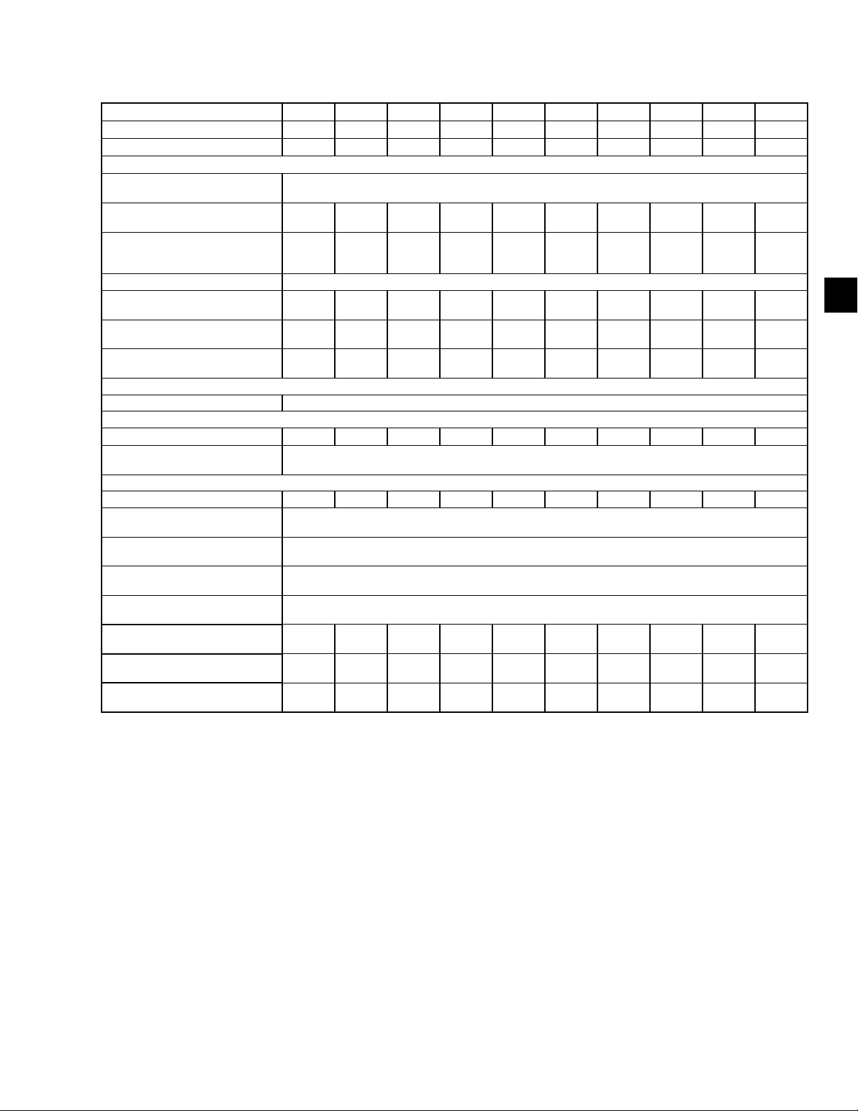
FORM QTC4-NM1
ISSUE DATE: 4/2/2018
SECTION 5 - TECHNICAL DATA
TABLE 6 - PHYSICAL DATA - ROUND TUBE COIL (CONT'D)
UNIT FRAME 320 330 340 370 405 450 460 470 480 500
CONDENSER CODE S S S S S S S C C S
EVAPORATOR CODE E C E F H G G K J J
GENERAL UNIT DATA
Number of Independent
Refrigerant Circuits
Refrigerant Charge, R-134a,
R-513A, Ckt.-1/Ckt.-2, lbs (kg)
Oil Charge, Ckt.-1/Ckt.-2,
gal (liters)
Minimum Load (%) 10%
Chassis Dimensions - Length,
inches (mm)
Chassis Dimensions - Width,
inches (mm)
Chassis Dimensions - Height,
inches (mm)
COMPRESSORS, SEMI-HERMETIC SCREW
Qty per Chiller 2
CONDENSER FANS
Number Ckt-1/Ckt-2 8/8 9/9 9/9 13/7 12/8 12/12 13/13 10/10 10/10 13/13
Air on Condenser
(Min/Max), °F (°C)
EVAPORATOR, SHELL AND TUBE HYBRID FALLING FILM
Water Volume, gal (liters) 113 (428) 71 (269) 113 (428) 96 (363) 130 (492) 96 (363) 96 (363) 130 (492) 147 (556) 147 (556)
Leaving Water Temperature
(Min/Max), °F (°C)
Maximum Water Side
Pressure, psig (barg)
Maximum Refrigerant Side
Pressure, psig (barg)
Evap Drain Connection,
inches (mm)
Minimum Chilled Water Flow
Rate, gpm (l/sec)
Maximum Chilled Water Flow
Rate, gpm (l/sec)
Inlet and Outlet Water
Connections, in
2
367/367
(166/166)
3.7/3.7
(14.0/
14.0)
379.2
(9631)
88.3
(2242)
94.6
(2403)
400
(25.2)
1500
(94.7)
371/371
(168/168)
3.7/3.7
(14.0/
14.0)
423.1
(10748)
88.3
(2242)
94.6
(2403)
(18.9)
1150
(72.6)
8 6 8 8 8 8 8 8 8 8
300
391/391
(177/177)
3.8/3.8
(14.4/
14.4)
423.1
(10748)
88.3
(2242)
94.6
(2403)
400
(25.2)
1500
(94.7)
537/308
(244/140)
4.0/2.9
(15.1/
11.0)
467.1
(11864)
88.3
(2243)
94.7
(2405)
460
(29.0)
1540
(97.0)
568/417
(258/189)
(11864)
4.0/4.0
(15.1/
15.1)
467.1
88.3
(2243)
94.7
(2405)
0/125
(-17.8/51.7)
40/60
(4.4/15.6)
(10.3)
(16.2)
520
(33.0)
1700
(107.0)
2
478/478
(217/217)
4.0/4.0
(15.1/
15.1)
555.3
(14104)
(2243)
(2405)
150
235
3/4
(29.0)
1540
(97.0)
88.3
94.7
460
502/502
(228/228)
4.0/4.0
(15.1/
15.1)
599.3
(15222)
88.4
(2244)
94.7
(2405)
460
(29.0)
1540
(97.0)
480/480
(218/218)
4.0/4.0
(15.1/
15.1)
467.1
(11864)
88.3
(2242)
94.6
(2403)
470
(30)
1870
(118)
495/495
(224/224)
4.0/4.0
(15.1/
15.1)
467.1
(11864)
88.4
(2244)
94.7
(2405)
550
(34.1)
1880
(118.1)
562/562
(255/255)
4.2/4.2
(15222)
(118.1)
(15.9/
15.9)
599.3
88.3
(2243)
94.7
(2405)
550
(34.1)
1880
5
NOTES:
1. Shipping and operating weights shown are for base unit; selected options may add weight to unit. Contact your nearest Quantech Sales
Representative for weight data.
2. For leaving liquid temperature below 40°F(4.4°C) or above 60°F (15.6°C). Contact your nearest Quantech Sales Representative for application requirements.
QUANTECH
63
Page 64
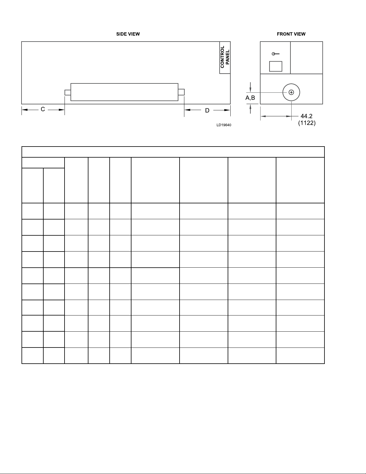
SECTION 5 - TECHNICAL DATA
TABLE 7 - OPTIONAL ONE-PASS EVAPORATOR
ALL DIMENSIONS - INCHES (MM)
FORM QTC4-NM1
ISSUE DATE: 4/2/2018
QTC4
MODEL
150 S
165 H
175 P
185 S
185 H
185 P
175 C
210 S
210 H
210 P
A,B C D
COND.
20.8
(528)
20.8
(528)
20.8
(528)
19.8
(503)
19.8
(503)
21
(533)
20.8
(528)
19.8
(503)
20.8
(528)
21
(533)
6.8
(173)
29.2
(742)
34.9
(886)
17.7
(450)
61.5
(1562)
117.3
(2979)
1.7
(43)
61.7
(1567)
34.9
(886)
78.9
(2044)
34.5
(876)
56.1
(1425)
70
(1778)
56.8
(1443)
56.7
(1425)
56.1
(1425)
38.1
(968)
56.8
(1443)
70
(1778)
70
(1778)
E
NOZZLE
SIZE
8
8
8
6
6
8
8
6
8
8
WATER
VOLUME.
GALLONS
(LITERS)
58
(220)
58
(220)
71
(269)
48
(182)
48
(182)
56
(220)
71
(269)
48
(182)
71
(269)
71
(269)
MINIMUM
CHILLED
WATER FLOW
RATE
GPM (L/S)
500
(32)
500
(32)
590
(37)
400
(25)
400
(25)
500
(32)
590
(37)
400
(25)
590
(37)
590
(37)
MAXIMUM
CHILLED
WATER FLOW
RATE
GPM (L/S)
1970
(124)
1970
(124)
2190
(138)
1230
(77)
1230
(77)
1970
(124)
2190
(138)
1230
(77)
2190
(138)
2190
(138)
NOTE: Minimum Chilled Water Flow Rate is for full load selections; Variable Primary Flow ratings as low as 50% of the minimum are permitted.
Glycol limits are higher. Please contact your Quantech Sales Representative for ratings and further information.
64
QUANTECH
Page 65

FORM QTC4-NM1
ISSUE DATE: 4/2/2018
TABLE 7 - OPTIONAL ONE-PASS EVAPORATOR (CONT'D)
ALL DIMENSIONS - INCHES (MM)
SECTION 5 - TECHNICAL DATA
5
QTC4
MODEL
230 S
240 H
240 P
260 S
270 C
270 S
270 H
270 P
290 H
300 S
A,B C D
COND.
20.8
(528)
21
(533)
21
(533)
21
(533)
21
(533)
21
(533)
22.5
(572)
22.5
(572)
22.5
(572)
21
(533)
73.2
(1859)
92.9
(2360)
122.9
(3122)
117.1
(2974)
16.8
(427)
42.9
(1090)
44.7
(1135)
88.3
(2243)
88.6
(2250)
122.9
(3122)
56.1
(1425)
56.1
(1425)
70
(1778)
56.1
(1425)
51.9
(1318)
70
(1778)
71.8
(1824)
71.8
(1824)
71.8
(1824)
70
(1778)
E
NOZZLE
SIZE
8
8
8
8
8
8
10
10
10
8
WATER
VOLUME.
GALLONS
(LITERS)
58
(220)
71
(269)
71
(269)
58
(220)
82
(310)
82
(310)
113
(428)
113
(428)
113
(428)
71
(269)
MINIMUM
CHILLED
WATER FLOW
RATE
GPM (L/S)
500
(32)
590
(37)
590
(37)
500
(32)
590
(37)
590
(37)
810
(51)
810
(51)
810
(51)
590
(37)
MAXIMUM
CHILLED
WATER FLOW
RATE
GPM (L/S)
1970
(124)
2190
(138)
2190
(138)
1970
(124)
2190
(138)
2190
(138)
3200
(202)
3200
(202)
3200
(202)
2190
(138)
NOTE: Minimum Chilled Water Flow Rate is for full load selections; Variable Primary Flow ratings as low as 50% of the minimum are permitted.
Glycol limits are higher. Please contact your Quantech Sales Representative for ratings and further information.
QUANTECH
65
Page 66
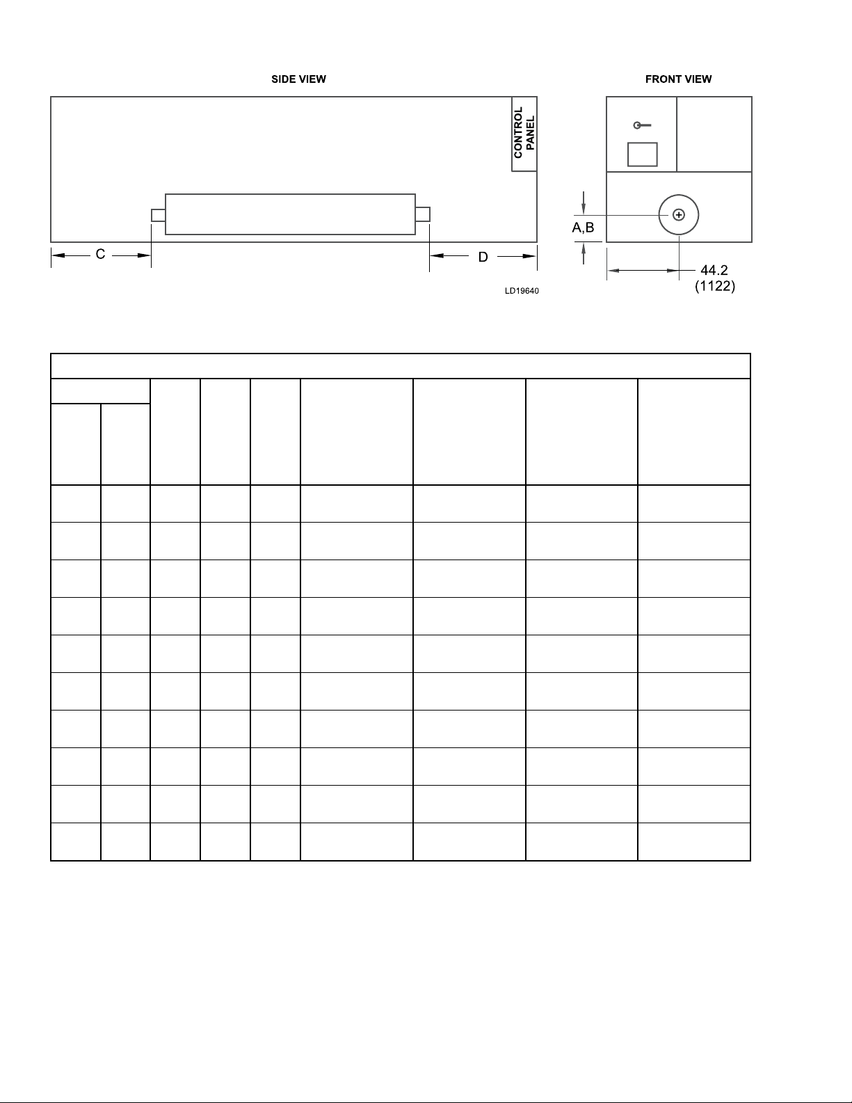
SECTION 5 - TECHNICAL DATA
TABLE 7 - OPTIONAL ONE-PASS EVAPORATOR (CONT'D)
ALL DIMENSIONS - INCHES (MM)
FORM QTC4-NM1
ISSUE DATE: 4/2/2018
QTC4
MODEL
300 H
310 P
315 P
320 S
330 S
340 S
340 H
370 P
370 S
370 H
A,B C D
COND.
21
(533)
22.5
(572)
22.5
(572)
22.5
(572)
21
(533)
22.5
(572)
22.5
(572)
23.3
(592)
22.3
(566)
23.3
(592)
166.9
(4239)
132.2
(3358)
176.6
(4486)
88.6
(2250)
166.9
(4239)
132.6
(3368)
176.21
(4476)
208.6
(5298)
180.9
(4595)
164.3
(4173)
70
(1778)
71.8
(1824)
71.8
(1824)
71.8
(1824)
70
(1778)
71.8
(1824)
71.8
(1824)
83.5
(2121)
112.2
(2850)
83.4
(2118)
E
NOZZLE
SIZE
8
10
10
10
8
10
10
10
10
10
WATER
VOLUME.
GALLONS
(LITERS)
71
(269)
113
(428)
113
(428)
113
(428)
71
(269)
113
(428)
113
(428)
147
(556)
96
(363)
147
(556)
MINIMUM
CHILLED
WATER FLOW
RATE
GPM (L/S)
590
(37)
810
(51)
810
(51)
810
(51)
590
(37)
810
(51)
810
(51)
1090
(69)
840
(53)
1090
(69)
MAXIMUM
CHILLED
WATER FLOW
RATE
GPM (L/S)
2190
(138)
3200
(202)
3200
(202)
3200
(202)
2190
(138)
3200
(202)
3200
(202)
3420
(215)
3320
(209)
3420
(215)
NOTE: Minimum Chilled Water Flow Rate is for full load selections; Variable Primary Flow ratings as low as 50% of the minimum are permitted.
Glycol limits are higher. Please contact your Quantech Sales Representative for ratings and further information.
66
QUANTECH
Page 67

FORM QTC4-NM1
ISSUE DATE: 4/2/2018
TABLE 7 - OPTIONAL ONE-PASS EVAPORATOR (CONT'D)
ALL DIMENSIONS - INCHES (MM)
SECTION 5 - TECHNICAL DATA
5
QTC4
MODEL
400 P
405 S
410 H
410 P
450 S
490 H
460 S
470 C
480 C
500 S
A,B C D
COND.
23.3
(592)
22.5
(572)
22.5
(572)
23.3
(592)
22.3
(566)
23.3
(592)
22.3
(566)
22.5
(571)
23.3
(592)
23.3
(592)
252.5
(6414)
164.6
(4181)
252.6
(6416)
296.5
(7531)
287.1
(7292)
308.4
(7833)
331.2
(8412)
176.5
(4482)
176.2
(4475)
308.4
(7833)
83.5
(2121)
83.8
(2129)
83.8
(2129)
83.5
(2121)
94.2
(2393)
71.5
(1816)
94.2
(2393)
71.7
(1820)
71.5
(1816)
71.5
(1816)
E
NOZZLE
SIZE
10
10
10
10
10
10
10
10
10
10
WATER
VOLUME.
GALLONS
(LITERS)
147
(556)
130
(492)
130
(492)
147
(556)
96
(363)
147
(556)
96
(363)
130
(492)
147
(556)
147
(556)
MINIMUM
CHILLED
WATER FLOW
RATE
GPM (L/S)
1090
(69)
940
(59)
940
(59)
1090
(69)
840
(53)
1090
(69)
840
(53)
940
(59)
1090
(69)
1090
(69)
MAXIMUM
CHILLED
WATER FLOW
RATE
GPM (L/S)
3420
(215)
3420
(215)
3420
(215)
3420
(215)
3320
(209)
3420
(215)
3320
(209)
3420
(215)
3420
(215)
3420
(215)
NOTE: Minimum Chilled Water Flow Rate is for full load selections; Variable Primary Flow ratings as low as 50% of the minimum are permitted.
Glycol limits are higher. Please contact your Quantech Sales Representative for ratings and further information.
QUANTECH
67
Page 68

SECTION 5 - TECHNICAL DATA
TABLE 8 - STANDARD TWO-PASS, REAR INLET/OUTLET EVAPORATOR
ALL DIMENSIONS - INCHES (MM)
FORM QTC4-NM1
ISSUE DATE: 4/2/2018
QTC4
MODEL
150 S
165 H
175 P
185 S
185 H
185 P
175 C
210 S
210 H
210 P
A B C DE NOZZLE
COND.
15.1
(384)
15.1
(384)
15.1
(384)
14.1
(358)
14.1
(358)
15.3
(389)
15.1
(384)
14.1
(358)
15.1
(384)
15.3
(389)
11.4
(290)
11.4
(290)
11.4
(290)
11.4
(290)
11.4
(290)
11.4
(290)
11.4
(290)
11.4
(290)
11.4
(290)
11.4
(290)
6.8
(173)
29.4
(747)
34.9
(886)
17.7
(450)
61.5
(1562)
117.3
(2979)
1.7
(43)
61.7
(1567)
29.9
(759)
78.9
(2004)
– 6
– 6
– 6
– 6
– 6
– 6
– 6
– 6
– 6
– 6
SIZE
F G
34.5
(876)
56.1
(1425)
70
(1778)
56.8
(1443)
56.7
(1440)
56.1
(1425)
38.1
(968)
58.8
(1494)
70
(1778)
70.3
(1786)
–
–
–
–
–
–
–
–
–
–
WATER
VOLUME
GALLONS
(LITERS)
58
(220)
58
(220)
71
(269)
48
(182)
48
(182)
58
(220)
71
(269)
48
(182)
71
(269)
71
(269)
MINIMUM
CHILLED
WATER
FLOW RATE
GPM (L/S)
250
(16)
250
(16)
300
(19)
200
(13)
200
(13)
250
(16)
300
(19)
200
(13)
300
(19)
300
(19)
MAXIMUM
CHILLED
WATER
FLOW RATE
GPM (L/S)
980
(62)
980
(62)
1170
(74)
790
(50)
790
(50)
980
(62)
1170
(74)
790
(50)
1170
(74)
1170
(74)
NOTE: Minimum Chilled Water Flow Rate is for full load selections; Variable Primary Flow ratings as low as 50% of the minimum are permitted.
Glycol limits are higher. Please contact your Quantech Sales Representative for ratings and further information.
68
QUANTECH
Page 69
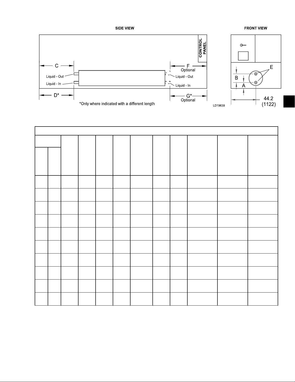
FORM QTC4-NM1
ISSUE DATE: 4/2/2018
TABLE 8 - STANDARD TWO-PASS, REAR INLET/OUTLET EVAPORATOR (CONT'D)
ALL DIMENSIONS - INCHES (MM)
SECTION 5 - TECHNICAL DATA
5
QTC4
MODEL
230 S
240 H
240 P
260 S
270 C
270 S
270 H
270 P
290 H
300 S
A B C D
COND.
15.1
(384)
15.3
(389)
15.3
(389)
15.3
(389)
15.3
(388)
15.3
(389)
15.5
(394)
15
(381)
15.5
(394)
15.3
(389)
11.4
(290)
11.4
(290)
11.4
(290)
11.4
(290)
11.4
(290)
11.4
(290)
14
(356)
14
(356)
14
(356)
11.4
(290)
73.3
(1862)
29.9
(759)
122.9
(3122)
117.3
(2979)
16.8
(427)
42.9
(1090)
44.3
(1125)
88.3
(2243)
88.3
(2243)
122.9
(3122)
NOZZLE
SIZE
– 6
– 6
– 6
– 6
– 6
– 6
– 8
– 8
– 8
– 6
E
F G
56.1
(1425)
56.1
(1425)
70
(1778)
56.1
(1425)
51.9
(1318)
70
(1778)
71.8
(1824)
71.8
(1824)
71.8
(1824)
70
(1778)
–
–
–
–
–
–
–
–
–
–
WATER
VOLUME
GALLONS
(LITERS)
58
(220)
71
(269)
71
(269)
58
(220)
82
(310)
82
(310)
113
(428)
113
(428)
113
(428)
71
(269)
MINIMUM
CHILLED
WATER
FLOW RATE
GPM (L/S)
250 (16) 980 (62)
300 (19) 1170 (74)
300 (19) 1170 (74)
250 (16) 980 (62)
300 (19) 1170 (74)
300 (19) 1170 (74)
410 (26) 1600 (101)
410 (26) 1600 (101)
410 (26) 1600 (101)
300 (19) 1170 (74)
MAXIMUM
CHILLED
WATER
FLOW RATE
GPM (L/S)
NOTE: Minimum Chilled Water Flow Rate is for full load selections; Variable Primary Flow ratings as low as 50% of the minimum are permitted.
Glycol limits are higher. Please contact your Quantech Sales Representative for ratings and further information.
QUANTECH
69
Page 70
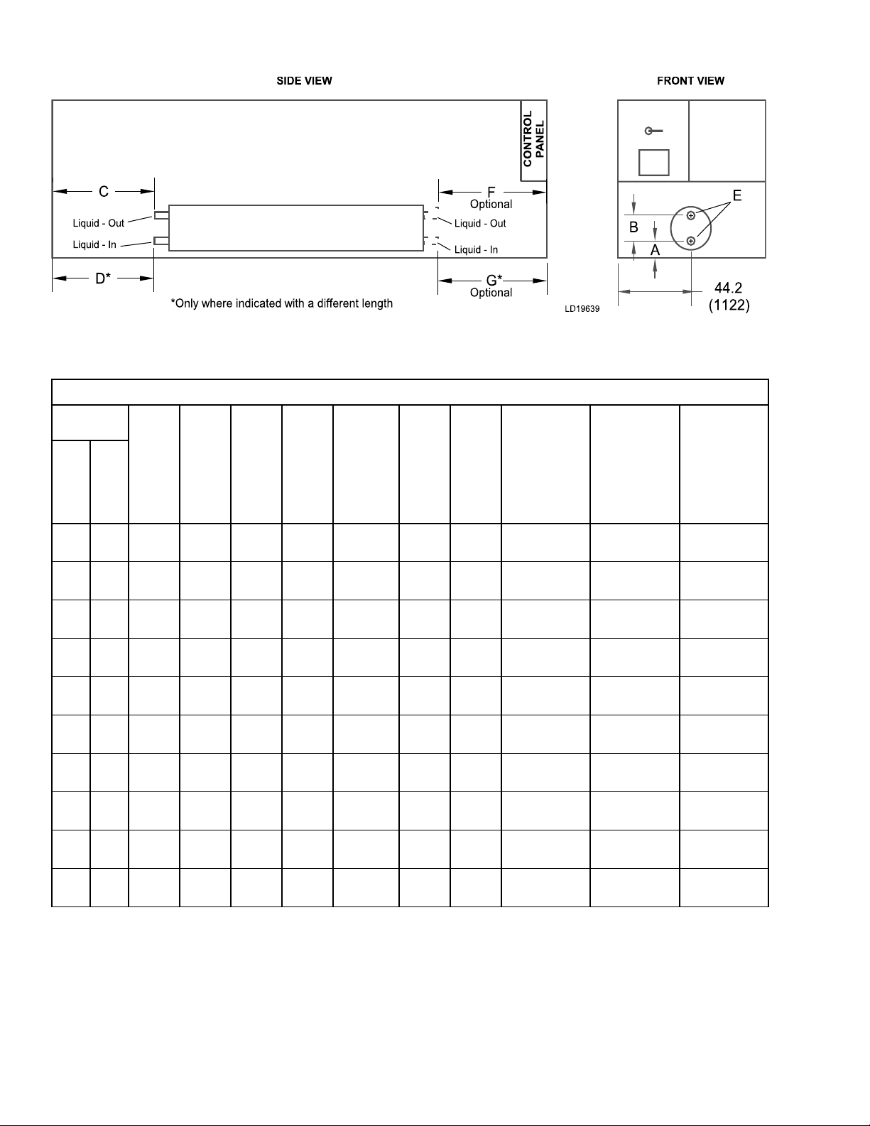
SECTION 5 - TECHNICAL DATA
TABLE 8 - STANDARD TWO-PASS, REAR INLET/OUTLET EVAPORATOR (CONT'D)
ALL DIMENSIONS - INCHES (MM)
FORM QTC4-NM1
ISSUE DATE: 4/2/2018
QTC4
MODEL
300 H
310 P
315 P
320 S
330 S
340 S
340 H
370 P
370 S
370 H
A B C DE NOZZLE
COND.
15.3
(389)
15.5
(394)
15.5
(394)
15.5
(394)
15.3
(389)
15.5
(394)
15.5
(394)
16.3
(414)
15.8
(401)
16.3
(414)
11.4
(290)
14
(356)
14
(356)
14
(356)
11.4
(290)
14
(356)
14
(356)
14
(356)
13
(330)
14
(356)
166.8
(4237)
132.2
(3358)
176.21
(4476)
88.6
(2250)
166.9
(4239)
132.2
(3358)
176.2
(4475)
208.5
(5296)
180.9
(4595)
164.4
(4176)
– 6
– 8
– 8
– 8
– 6
– 8
– 8
– 8
176.4
(4480)
– 8
SIZE
8
F G
70
(1778)
83.4
(2118)
83.4
(2118)
83.4
(2118)
83.4
(2118)
83.4
(2118)
83.4
(2118)
83.4
(2118)
112.2
(2850)
83.4
(2118)
–
–
–
–
–
–
–
–
107.7
(2735)
–
WATER
VOLUME
GALLONS
(LITERS)
71
(269)
113
(428)
113
(428)
113
(428)
71
(269)
113
(428)
113
(428)
147
(556)
96
(363)
147
(556)
MINIMUM
CHILLED
WATER
FLOW RATE
GPM (L/S)
MAXIMUM
CHILLED
WATER
FLOW RATE
GPM (L/S)
300 (19) 1170 (74)
410 (26) 1600 (101)
410 (26) 1600 (101)
410 (26) 1600 (101)
300 (19) 1170 (74)
410 (26) 1600 (101)
410 (26) 1600 (101)
550 (35) 2160 (136)
420 (26) 1660 (105)
550 (35) 2160 (136)
NOTE: Minimum Chilled Water Flow Rate is for full load selections; Variable Primary Flow ratings as low as 50% of the minimum are permitted.
Glycol limits are higher. Please contact your Quantech Sales Representative for ratings and further information.
70
QUANTECH
Page 71
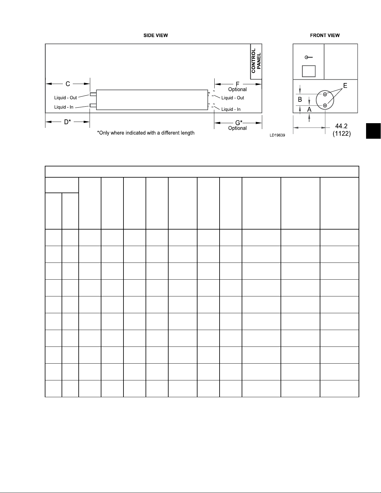
FORM QTC4-NM1
ISSUE DATE: 4/2/2018
TABLE 8 - STANDARD TWO-PASS, REAR INLET/OUTLET EVAPORATOR (CONT'D)
ALL DIMENSIONS - INCHES (MM)
SECTION 5 - TECHNICAL DATA
5
QTC4
MODEL
400 P
405 S
410 H
410 P
450 S
490 H
460 S
470 C
480 C
500 S
A B C D
COND.
16.3
(414)
15.5
(394)
15.5
(394)
16.3
(414)
15.8
(401)
16.3
(414)
15.8
(401)
15.5
(394)
16.3
(414)
16.3
(414)
14
(356)
14
(356)
14
(356)
14
(356)
13
(330)
14
(356)
13
(330)
14
(355)
14
(356)
14
(356)
252.5
(6414)
164.6
(4181)
252.6
(6416)
296.5
(7531)
287.1
(7292)
308.4
(7833)
331.2
(8412)
176.5
(4482)
176.2
(4475)
308.4
(7833)
– 8
– 8
– 8
– 8
282.5
(7177)
– 8
326.6
(8296)
– 8
– 8
– 8
E
NOZZLE
SIZE
8
8
F G
83.5
(2121)
83.8
(2129)
83.8
(2129)
83.5
(2121)
94.2
(2393)
71.5
(1816)
94.2
(2393)
71.7
(1820)
71.5
(1816)
71.5
(1816)
–
–
–
–
89.7
(2278)
–
89.7
(2278)
–
–
–
WATER
VOLUME
GALLONS
(LITERS)
147
(556)
130
(492)
130
(492)
147
(556)
96
(363)
147
(556)
96
(363)
130
(492)
147
(556)
147
(556)
MINIMUM
CHILLED
WATER
FLOW RATE
GPM (L/S)
550 (35) 2160 (136)
470 (30) 1870 (118)
470 (30) 1870 (118)
550 (35) 2160 (136)
420 (26) 1660 (105)
550 (35) 2160 (136)
420 (26) 1660 (105)
470 (30) 1870 (118)
550 (35) 2160 (136)
550 (35) 2160 (136)
MAXIMUM
CHILLED
WATER
FLOW RATE
GPM (L/S)
NOTE: Minimum Chilled Water Flow Rate is for full load selections; Variable Primary Flow ratings as low as 50% of the minimum are permitted.
Glycol limits are higher. Please contact your Quantech Sales Representative for ratings and further information.
QUANTECH
71
Page 72
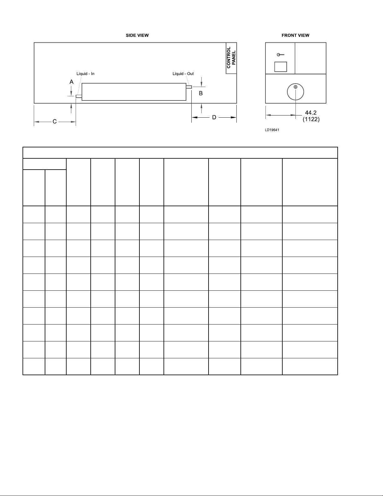
SECTION 5 - TECHNICAL DATA
TABLE 9 - OPTIONAL THREE-PASS REAR INLET/FRONT OUTLET EVAPORATOR
ALL DIMENSIONS - INCHES (MM)
FORM QTC4-NM1
ISSUE DATE: 4/2/2018
QTC4
MODEL
150 S
165 H
175 P
185 S
185 H
185 P
175 C
210 S
210 H
210 P
COND.
A B C D
15.1
(384)
15.1
(384)
15.1
(384)
25.5
(648)
14.1
(358)
15.3
(389)
15.1
(384)
14.1
(358)
15.1
(384)
15.3
(389)
26.5
(673)
26.5
(673)
26.5
(673)
25.5
(648)
25.5
(648)
26.7
(678)
26.53
(674)
25.5
(648)
26.5
(673)
26.7
(678)
6.8
(173)
29.2
(742)
34.9
(886)
17.7
(450)
61.5
(1562)
117.3
(2979)
1.7
(43)
61.6
(1565)
34.9
(886)
78.9
(2004)
34.5
(876)
56.1
(1425)
70
(1778)
56.8
(1443)
56.7
(1440)
56.1
(1425)
38.1
(968)
58.8
(1494)
70
(1778)
70.3
(1786)
E
NOZZLE
SIZE
5
5
6
5
5
5
6
5
6
6
WATER
VOLUME
GALLONS
(LITERS)
58
(220)
58
(220)
71
(269)
48
(182)
48
(182)
58
(220)
71
(269)
48
(182)
71
(269)
71
(269)
MINIMUM
CHILLED
MAXIMUM
CHILLED
WATER FLOW
RATE
GPM (L/S)
FLOW RATE
GPM (L/S)
170 (11) 650 (41)
170 (11) 650 (41)
200 (13) 780 (49)
130 (8) 520 (33)
130 (8) 520 (33)
170 (11) 650 (41)
200 (13) 780 (49)
130 (8) 520 (33)
200 (13) 780 (49)
200 (13) 780 (49)
WATER
NOTE: Minimum Chilled Water Flow Rate is for full load selections; Variable Primary Flow ratings as low as 50% of the minimum are permitted.
Glycol limits are higher. Please contact your Quantech Sales Representative for ratings and further information.
72
QUANTECH
Page 73
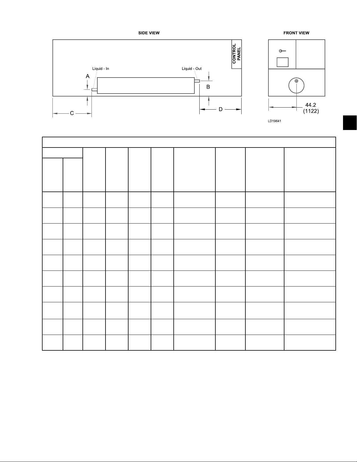
FORM QTC4-NM1
ISSUE DATE: 4/2/2018
SECTION 5 - TECHNICAL DATA
TABLE 9 - OPTIONAL THREE-PASS REAR INLET/FRONT OUTLET EVAPORATOR (CONT'D)
ALL DIMENSIONS - INCHES (MM)
QTC4
MODEL
230 S
240 H
240 P
260 S
270 C
270 S
270 H
270
290 H
300 S
COND.
P
A B C D
14.1
(358)
15.3
(389)
15.3
(389)
15.3
(389)
15.3
(388)
15.3
(389)
15.5
(394)
15.5
(394)
15.5
(394)
15.3
(389)
25.5
(648)
26.7
(678)
26.7
(678)
26.7
(678)
26.7
(678)
26.7
(678)
29.5
(749)
29.5
(749)
29.5
(749)
26.7
(678)
73.2
(1859)
29.9
(759)
122.9
(3122)
117.1
(2974)
16.8
(427)
42.9
(1090)
88.6
(2250)
88.3
(2243)
88.6
(2250)
122.9
(3122)
56.1
(1425)
56.1
(1425)
70
(1778)
56.1
(1425)
51.9
(1318)
70
(1778)
71.8
(1824)
71.8
(1824)
71.8
(1824)
70
(1778)
E
NOZZLE
SIZE
5
6
6
5
6
6
6
6
6
6
WATER
VOLUME
GALLONS
(LITERS)
58
(220)
71
(269)
71
(269)
58
(220)
82
(310)
82
(310)
113
(428)
113
(428)
113
(428)
71
(269)
MINIMUM
CHILLED
WATER FLOW
RATE
GPM (L/S)
170 (11) 650 (41)
200 (13) 780 (49)
200 (13) 780 (49)
170 (11) 650 (41)
200 (13) 780 (49)
200 (13) 780 (49)
270 (17) 1060 (67)
270 (17) 1060 (67)
270 (17) 1060 (67)
200 (13) 780 (49)
5
MAXIMUM
CHILLED
WATER
FLOW RATE
GPM (L/S)
NOTE: Minimum Chilled Water Flow Rate is for full load selections; Variable Primary Flow ratings as low as 50% of the minimum are permitted.
Glycol limits are higher. Please contact your Quantech Sales Representative for ratings and further information.
QUANTECH
73
Page 74

SECTION 5 - TECHNICAL DATA
TABLE 9 - OPTIONAL THREE-PASS REAR INLET/FRONT OUTLET EVAPORATOR (CONT'D)
ALL DIMENSIONS - INCHES (MM)
FORM QTC4-NM1
ISSUE DATE: 4/2/2018
QTC4
MODEL
300 H
310 P
315 P
320 S
330 S
340 S
340 H
370 P
370 S
370 H
COND.
A B C D
15.3
(389)
15
(381)
15
(381)
15.5
(394)
15.3
(389)
15.5
(394)
15.5
(394)
16.3
(414)
15.8
(401)
16.3
(414)
26.7
(678)
30.3
(770)
29.5
(749)
29.5
(749)
26.7
(678)
29.5
(749)
29.5
(749)
30.3
(770)
28.8
(732)
30.3
(770)
166.9
(4239)
132.2
(3358)
176.6
(4486)
88.6
(2250)
166.9
(4239)
132.6
(3368)
176.2
(4475)
208.6
(5298)
180.9
(4595)
164.3
(4173)
70
(1778)
71.8
(1824)
71.8
(1824)
71.8
(1824)
70
(1778)
71.8
(1824)
71.8
(1824)
83.5
(2121)
112.2
(2850)
83.4
(2118)
E
NOZZLE
SIZE
6
6
6
6
6
6
6
8
6
8
WATER
VOLUME
GALLONS
(LITERS)
71
(269)
113
(428)
113
(428)
113
(428)
71
(269)
113
(428)
113
(428)
147
(556)
94
(356)
147
(556)
MINIMUM
CHILLED
WATER FLOW
RATE
GPM (L/S)
MAXIMUM
CHILLED
WATER
FLOW RATE
GPM (L/S)
200 (13) 780 (49)
270 (17) 1060 (67)
270 (17) 1060 (67)
270 (17) 1060 (67)
200 (13) 780 (49)
270 (17) 1060 (67)
270 (17) 1060 (67)
370 (23) 1440 (91)
280 (18) 1100 (69)
370 (23) 1440 (91)
NOTE: Minimum Chilled Water Flow Rate is for full load selections; Variable Primary Flow ratings as low as 50% of the minimum are permitted.
Glycol limits are higher. Please contact your Quantech Sales Representative for ratings and further information.
74
QUANTECH
Page 75
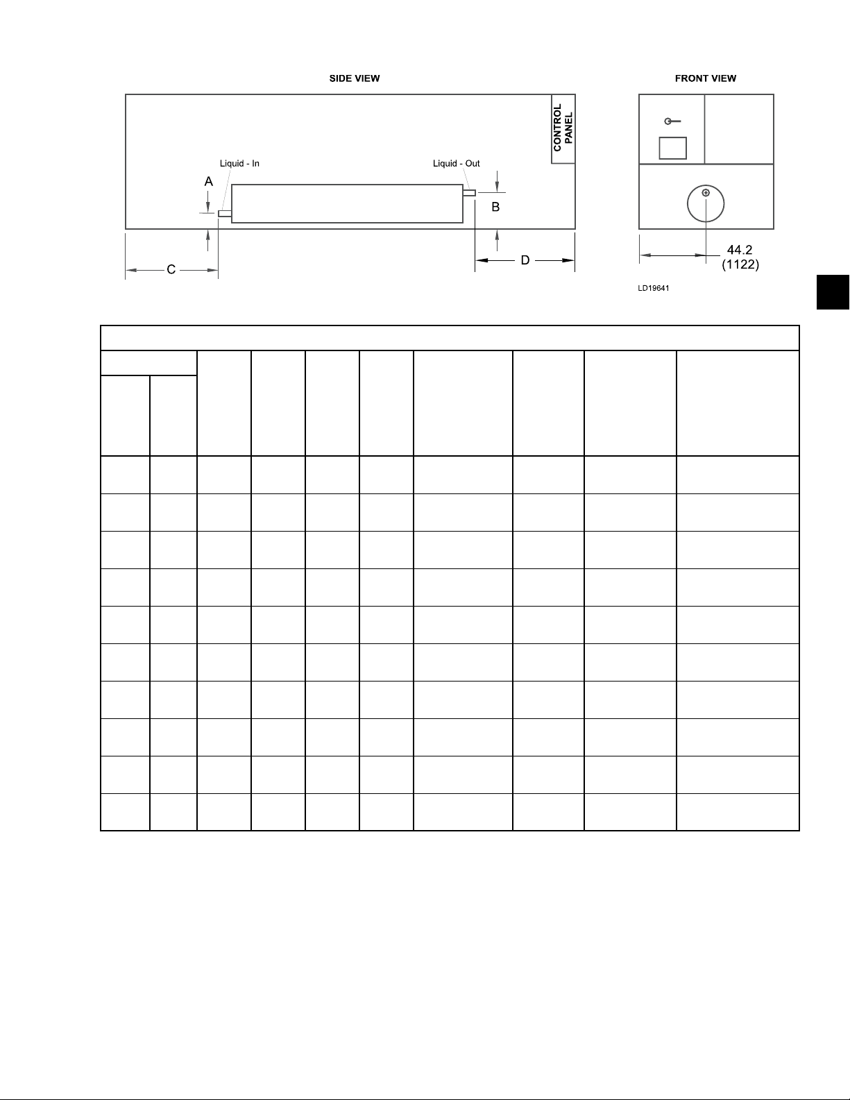
FORM QTC4-NM1
ISSUE DATE: 4/2/2018
SECTION 5 - TECHNICAL DATA
TABLE 9 - OPTIONAL THREE-PASS REAR INLET/FRONT OUTLET EVAPORATOR (CONT'D)
ALL DIMENSIONS - INCHES (MM)
QTC4
MODEL
400 P
405 S
410 H
410 P
450 S
490 H
460 S
470 C
480 C
500 S
COND.
A B C D
16.3
(414)
15.5
(394)
15.5
(394)
16.3
(414)
15.8
(401)
16.3
(414)
15.8
(401)
15.5
(394)
16.3
(414)
16.3
(414)
30.3
(770)
29.5
(749)
29.5
(749)
30.3
(770)
28.8
(732)
30.3
(770)
28.8
(732)
29.5
(749)
30.3
(770)
30.3
(770)
252.5
(6414)
164.6
(4181)
252.6
(6416)
296.5
(7531)
287.1
(7292)
308.4
(7833)
331.2
(8412)
176.2
(4476)
176.2
(4475)
308.4
(7833)
83.5
(2121)
83.8
(2129)
83.8
(2129)
83.5
(2121)
94.2
(2393)
71.5
(1816)
94.2
(2393)
71.5
(1817)
71.5
(1816)
71.5
(1816)
E
NOZZLE
SIZE
8
6
6
8
6
8
6
6
8
8
WATER
VOLUME
GALLONS
(LITERS)
147
(556)
128
(485)
128
(485)
147
(556)
94
(356)
147
(556)
94
(356)
130
(492)
147
(556)
147
(556)
MINIMUM
CHILLED
WATER FLOW
RATE
GPM (L/S)
370 (23) 1440 (91)
320 (20) 1230 (77)
320 (20) 1230 (77)
370 (23) 1440 (91)
280 (18) 1100 (69)
370 (23) 1440 (91)
280 (18) 1100 (69)
320 (20) 1230 (77)
370 (23) 1440 (91)
370 (23) 1440 (91)
5
MAXIMUM
CHILLED
WATER
FLOW RATE
GPM (L/S)
NOTE: Minimum Chilled Water Flow Rate is for full load selections; Variable Primary Flow ratings as low as 50% of the minimum are permitted.
Glycol limits are higher. Please contact your Quantech Sales Representative for ratings and further information.
QUANTECH
75
Page 76
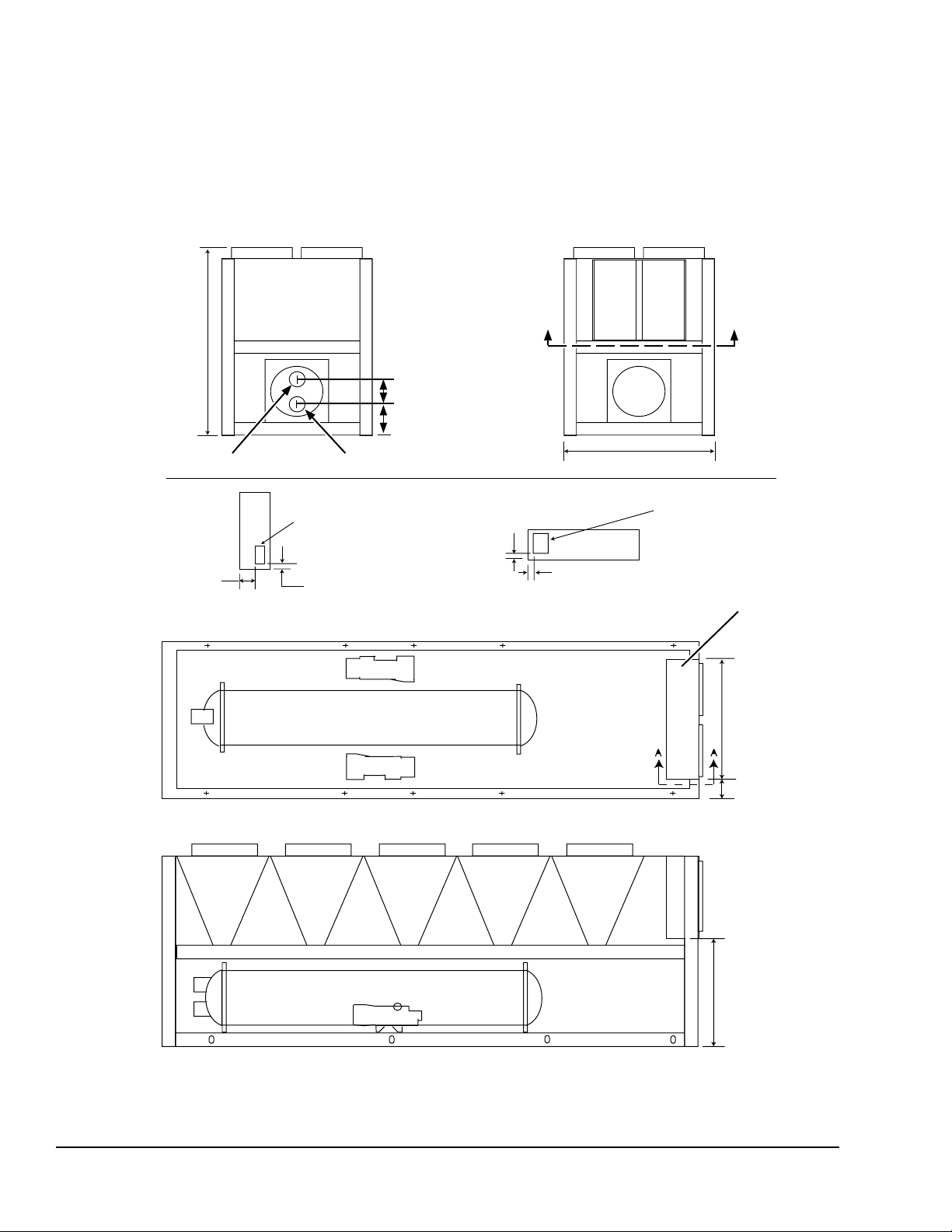
SECTION 5 - TECHNICAL DATA
FORM QTC4-NM1
ISSUE DATE: 4/2/2018
The data below is applicable to select configurations.
Other configurations are available through our configuration/selection software.
94.6"
(2403 mm)
C
B
A" PIPE WATER OUTLET
120"
(305 mm)
VIEW A-A
A" PIPE WATER INLET
CONTROL ENTRY
3.0" (76 mm) WIDE X
11.5" (292 mm) HIGH
3.0"
(75 mm)
Please contact your nearest Quantech Sales Representative for the chiller configuration that best matches
your specific needs.
BB
LD16178
88.3" (2242 mm)
4.0"
(102 mm)
1.5"
(38 mm)
VIEW B-B
POWER ENTRY
10" (254 mm) WIDE X
13" (330 mm) HIGH
VSD / CONTROL PANEL
FIGURE 16 - QTC4 DIMENSIONS
60.0"
(1524 mm)
14.1"
(359 mm)
47.4"
(1204 mm)
76
QUANTECH
Page 77

FORM QTC4-NM1
ISSUE DATE: 03/07/2018
SECTION 5 - TECHNICAL DATA
THIS PAGE INTENTIONALLY LEFT BLANK
QUANTECH
77
Page 78
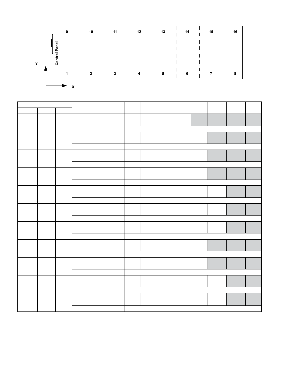
SECTION 5 - TECHNICAL DATA
TABLE 10 - ISOLATOR SELECTION AND MOUNTING LOCATIONS
QTC4 CONFIGURATION
MODEL COND EVAP
150 S B
165 H B
175 P C
185 S A
185 H A
185 P B
175 C C
210 S A
210 H C
210 P C
230 S B
DESCRIPTION 1 2 3 4 5 6 7 8
Isolator X-Dimension
10
(263)
73
(1852)
(3662)
Isolator Y-Dimension 1 (34)
Isolator X-Dimension
10
(263)
77
(1943)
(3000)
Isolator Y-Dimension 1 (34)
Isolator X-Dimension
10
(263)
81
(2057)
(3779)
Isolator Y-Dimension 1 (34)
Isolator X-Dimension
10
(263)
76
(1943)
(3152)
Isolator Y-Dimension 1 (34)
Isolator X-Dimension
10
(259)
76
(1939)
(2997)
Isolator Y-Dimension 1 (34)
Isolator X-Dimension
10
(263)
76
(1943)
(3000)
Isolator Y-Dimension 1 (34)
Isolator X-Dimension
10
(263)
76
(1943)
(3000)
Isolator Y-Dimension 1 (34)
Isolator X-Dimension
10
(263)
81
(2057)
(3779)
Isolator Y-Dimension 1 (34)
Isolator X-Dimension
10
(263)
81
(2057)
(3779)
Isolator Y-Dimension 1 (34)
Isolator X-Dimension
10
(263)
81
(2057)
(3779)
Isolator Y-Dimension 1 (34)
Isolator X-Dimension
10
(263)
76
(1943)
(2999)
Isolator Y-Dimension 1 (34)
144
118
149
124
118
118
118
149
149
149
118
193
(4900)
157
(3985)
187
(4756)
163
(4137)
157
(3982)
157
(3985)
157
(3985)
187
(4756)
187
(4756)
187
(4756)
157
(3984)
220
(5589)
251
(6368)
210
(5323)
208
(5295)
209
(5299)
209
(5299)
251
(6368)
251
(6368)
235
(5968)
209
(5298)
FORM QTC4-NM1
ISSUE DATE: 4/2/2018
281
(7132)
308
(7823)
281
(7136)
301
(7653)
281
(7135)
NOTES:
1. Contact your nearest Quantech Sales Representative for weight data.
2. All isolator mounting holes are 19mm.
3. Dimensions are in inches (mm).
78
QUANTECH
Page 79

FORM QTC4-NM1
ISSUE DATE: 4/2/2018
SECTION 5 - TECHNICAL DATA
TABLE 10 - ISOLATOR SELECTION AND MOUNTING LOCATIONS (CONT'D)
QTC4 CONFIGURATION
MODEL COND EVAP
150 S B
165 H B
175 P C
185 S A
185 H A
185 P B
175 C C
210 S A
210 H C
210 P C
230 S B
DESCRIPTION 9 10 11 12 13 14 15 16
Isolator X-Dimension
Isolator Y-Dimension 87 (2206)
Isolator X-Dimension
Isolator Y-Dimension 87 (2206)
Isolator X-Dimension
Isolator Y-Dimension 87 (2206)
Isolator X-Dimension
Isolator Y-Dimension 87 (2206)
Isolator X-Dimension
Isolator Y-Dimension 87 (2206)
Isolator X-Dimension
Isolator Y-Dimension 87 (2206)
Isolator X-Dimension
Isolator Y-Dimension 87 (2206)
Isolator X-Dimension
Isolator Y-Dimension 87 (2206)
Isolator X-Dimension
Isolator Y-Dimension 87 (2206)
Isolator X-Dimension
Isolator Y-Dimension 87 (2206)
Isolator X-Dimension
Isolator Y-Dimension 87 (2206)
10
(263)
10
(263)
10
(263)
10
(263)
10
(259)
10
(263)
10
(263)
10
(263)
10
(263)
10
(263)
10
(263)
73
(1852)
77
(1943)
81
(2057)
76
(1943)
76
(1939)
76
(1943)
76
(1943)
81
(2057)
81
(2057)
81
(2057)
76
(1943)
144
(3662)
118
(3000)
149
(3779)
124
(3152)
118
(2997)
118
(3000)
118
(3000)
149
(3779)
149
(3779)
149
(3779)
118
(2999)
193
(4900)
157
(3985)
187
(4756)
163
(4137)
157
(3982)
157
(3985)
157
(3985)
187
(4756)
187
(4756)
187
(4756)
157
(3984)
220
(5589)
251
(6368)
210
(5323)
208
(5295)
209
(5299)
209
(5299)
251
(6368)
251
(6368)
235
(5968)
209
(5298)
5
281
(7132)
308
(7823)
281
(7136)
301
(7653)
281
(7135)
NOTES:
1. Contact your nearest Quantech Sales Representative for weight data.
2. All isolator mounting holes are 19mm.
3. Dimensions are in inches (mm)..
QUANTECH
79
Page 80

SECTION 5 - TECHNICAL DATA
TABLE 10 - ISOLATOR SELECTION AND MOUNTING LOCATIONS (CONT'D)
QTC4 CONFIGURATION
MODEL COND EVAP
240 H C
240 P C
260 S B
270 C D
270 S D
270 H E
270 P E
290 H E
300 S C
300 H C
310 P E
315 P E
320 S E
330 S C
340 S E
DESCRIPTION 1 2 3 4 5 6 7 8
Isolator X-Dimension
10
(263)
76
(1943)
128
(3260)
173
(4391)
Isolator Y-Dimension 1 (34)
Isolator X-Dimension
10
(263)
81
(2057)
143
(3638)
187
(4748)
Isolator Y-Dimension 1 (34)
Isolator X-Dimension
10
(263)
77
(1943)
118
(2999)
157
(3984)
Isolator Y-Dimension 1 (34)
Isolator X-Dimension
10
(263)
81
(2057)
149
(3779)
187
(4756)
Isolator Y-Dimension 1 (34)
Isolator X-Dimension
10
(263)
81
(2057)
161
(4084)
201
(5105)
Isolator Y-Dimension 1 (34)
Isolator X-Dimension
10
(263)
81
(2057)
161
(4084)
201
(5105)
Isolator Y-Dimension 1 (34)
Isolator X-Dimension
10
(263)
81
(2057)
161
(4095)
201
(5105)
Isolator Y-Dimension 1 (34)
Isolator X-Dimension
10
(263)
81
(2057)
161
(4095)
201
(5105)
Isolator Y-Dimension 1 (34)
Isolator X-Dimension
10
(263)
81
(2057)
143
(3638)
187
(4748)
Isolator Y-Dimension 1 (34)
Isolator X-Dimension
10
(260)
81
(2057)
144
(3663)
187
(4755)
Isolator Y-Dimension 1 (34)
Isolator X-Dimension
10
(260)
81
(2054)
161
(4081)
201
(5102)
Isolator Y-Dimension 1 (34)
Isolator X-Dimension
10
(263)
81
(2057)
161
(4084)
201
(5105)
Isolator Y-Dimension 1 (34)
Isolator X-Dimension
10
(263)
81
(2057)
161
(4084)
201
(5105)
Isolator Y-Dimension 1 (34)
Isolator X-Dimension
10
(263)
81
(2057)
143
(3636)
188
(4781)
Isolator Y-Dimension 1 (34)
Isolator X-Dimension
10
(263)
81
(2057)
161
(4084)
201
(5105)
Isolator Y-Dimension 1 (34)
220
(5579)
245
(6232)
209
(5298)
264
(6709)
301
(7654)
301
(7654)
298
(7582)
296
(7512)
245
(6232)
277
(7047)
298
(7579)
298
(7582)
298
(7582)
245
(6232)
298
(7582)
FORM QTC4-NM1
ISSUE DATE: 4/2/2018
301
(7654)
339
(8609)
308
(7823)
339
(8609)
339
(8609)
339
(8608)
383
(9726)
383
(9723)
427
(10843)
339
(8609)
383
(9726)
383
(9726)
NOTES:
1. Contact your nearest Quantech Sales Representative for weight data.
2. All isolator mounting holes are 19mm.
3. Dimensions are in inches (mm).
80
QUANTECH
Page 81
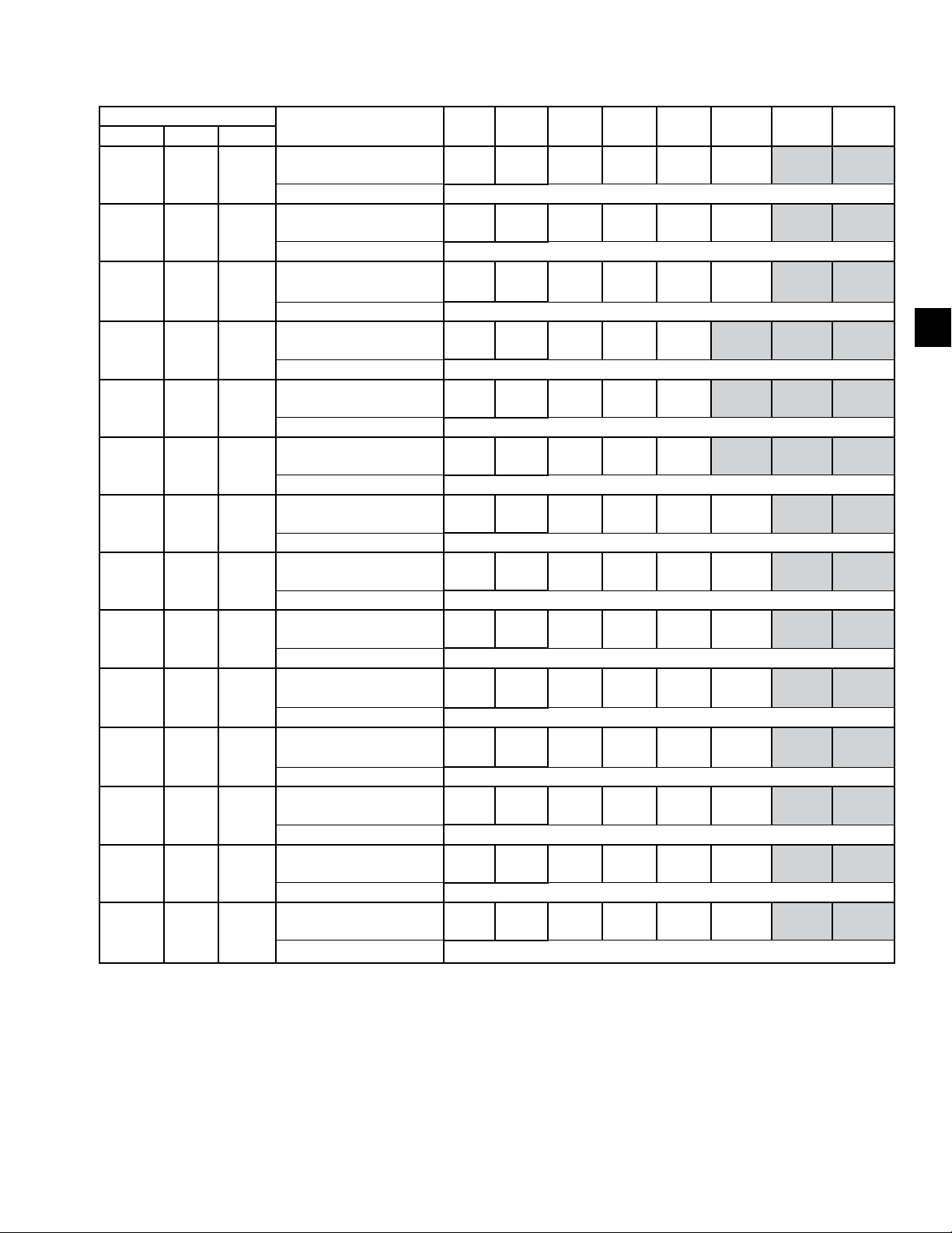
FORM QTC4-NM1
ISSUE DATE: 4/2/2018
TABLE 10 - ISOLATOR SELECTION AND MOUNTING LOCATIONS (CONT'D)
QTC4 CONFIGURATION
MODEL COND EVAP
240 H C
240 P C
260 S B
270 C D
270 S D
270 H E
270 P E
290 H E
300 S C
300 H C
310 P E
315 P E
320 S E
330 S C
DESCRIPTION 9 10 11 12 13 14 15 16
Isolator X-Dimension
Isolator Y-Dimension 87 (2206)
Isolator X-Dimension
Isolator Y-Dimension 87 (2206)
Isolator X-Dimension
Isolator Y-Dimension 87 (2206)
Isolator X-Dimension
Isolator Y-Dimension 1 (34)
Isolator X-Dimension
Isolator Y-Dimension 87 (2206)
Isolator X-Dimension
Isolator Y-Dimension 87 (2206)
Isolator X-Dimension
Isolator Y-Dimension 87 (2206)
Isolator X-Dimension
Isolator Y-Dimension 87 (2206)
Isolator X-Dimension
Isolator Y-Dimension 87 (2206)
Isolator X-Dimension
Isolator Y-Dimension 87 (2206)
Isolator X-Dimension
Isolator Y-Dimension 87 (2206)
Isolator X-Dimension
Isolator Y-Dimension 87 (2206)
Isolator X-Dimension
Isolator Y-Dimension 87 (2206)
Isolator X-Dimension
Isolator Y-Dimension 87 (2206)
10
(263)
10
(263)
10
(263)
10
(263)
10
(263)
10
(263)
10
(263)
10
(263)
10
(263)
10
(260)
10
(260)
10
(263)
10
(263)
10
(263)
76
(1943)
81
(2057)
77
(1943)
81
(2057)
81
(2057)
81
(2057)
81
(2057)
81
(2057)
81
(2057)
81
(2057)
81
(2054)
81
(2057)
81
(2057)
81
(2057)
128
(3260)
143
(3638)
118
(2999)
149
(3779)
161
(4084)
161
(4084)
161
(4095)
161
(4095)
143
(3638)
144
(3663)
161
(4081)
161
(4084)
161
(4084)
143
(3636)
173
(4391)
187
(4748)
157
(3984)
187
(4756)
201
(5105)
201
(5105)
201
(5105)
201
(5105)
187
(4748)
187
(4755)
201
(5102)
201
(5105)
201
(5105)
188
(4781)
220
(5579)
245
(6232)
209
(5298)
264
(6709)
301
(7654)
301
(7654)
298
(7582)
296
(7512)
245
(6232)
277
(7047)
298
(7579)
298
(7582)
298
(7582)
245
(6232)
SECTION 5 - TECHNICAL DATA
301
(7654)
339
(8609)
308
(7823)
5
339
(8609)
339
(8609)
339
(8608)
383
(9726)
383
(9723)
427
(10843)
339
(8609)
383
(9726)
NOTES:
1. Contact your nearest Quantech Sales Representative for weight data.
2. All isolator mounting holes are 19mm.
3. Dimensions are in inches (mm)..
QUANTECH
81
Page 82
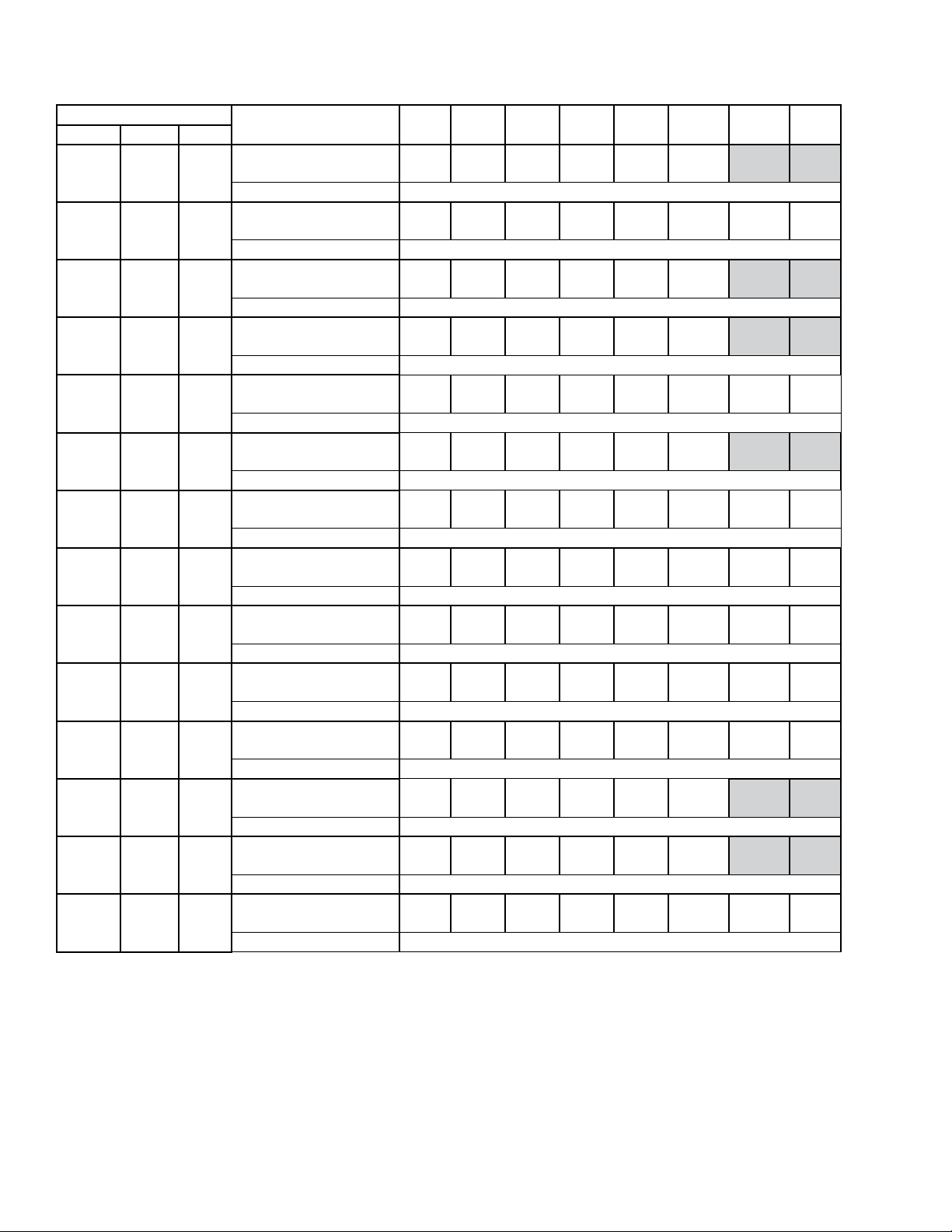
SECTION 5 - TECHNICAL DATA
TABLE 10 - ISOLATOR SELECTION AND MOUNTING LOCATIONS (CONT'D)
QTC4 CONFIGURATION
MODEL COND EVAP
340 H E
370 P J
370 S F
370 H J
400 P J
405 S H
410 H H
410 P J
450 S G
490 H J
460 S G
470 C K
480 C J
500 S J
DESCRIPTION 1 2 3 4 5 6 7 8
Isolator X-Dimension
10
(263)
81
(2057)
161
(4084)
201
(5105)
Isolator Y-Dimension 1 (34)
Isolator X-Dimension
10
(263)
81
(2057)
145
(3680)
205
(5219)
Isolator Y-Dimension 1 (34)
Isolator X-Dimension
10
(263)
81
(2057)
145
(3680)
206
(5219)
Isolator Y-Dimension
Isolator X-Dimension
10
(263)
81
(2057)
145
(3680)
206
(5219)
Isolator Y-Dimension
Isolator X-Dimension
10
(254)
81
(2057)
154
(3912)
206
(5232)
Isolator Y-Dimension
Isolator X-Dimension
10
(263)
81
(2057)
145
(3680)
205
(5219)
Isolator Y-Dimension
Isolator X-Dimension
10
(254)
81
(2057)
145
(3680)
206
(5219)
Isolator Y-Dimension
Isolator X-Dimension
10
(260)
81
(2054)
145
(3677)
205
(5216)
Isolator Y-Dimension
Isolator X-Dimension
10
(263)
81
(2057)
154
(3907)
206
(5219)
Isolator Y-Dimension
Isolator X-Dimension
10
(263)
81
(2057)
154
(3907)
206
(5219)
Isolator Y-Dimension
Isolator X-Dimension
10
(263)
81
(2057)
154
(3907)
206
(5219)
Isolator Y-Dimension
Isolator X-Dimension
10
(263)
81
(2057)
154
(3907)
205
(5219)
Isolator Y-Dimension
Isolator X-Dimension
10
(263)
81
(2057)
154
(2908)
205
(5219)
Isolator Y-Dimension 1 (34)
Isolator X-Dimension
10
(263)
81
(2057)
154
(3907)
206
(5219)
Isolator Y-Dimension 1 (34)
(7582)
(7218)
(7218)
1 (34)
(7218)
1 (34)
(7214)
1 (34)
(7218)
1 (34)
(7218)
1 (34)
(7215)
1 (34)
(7218)
1 (34)
(7218)
1 (34)
(7218)
1 (34)
(7218)
1 (34)
(7218)
(7218)
298
284
284
284
284
284
284
284
284
284
284
284
284
284
FORM QTC4-NM1
ISSUE DATE: 4/2/2018
427
(10843)
383
(9725)
439
(11157)
427
(10842)
427
(10842)
427
(10846)
483
(12268)
427
(10843)
427
(10842)
427
(10839)
427
(10842)
427
(10842)
427
(10842)
483
(12274)
505
(12817)
483
(12274)
505
(12820)
505
(12820)
427
(10842)
427
(10843)
427
(10842)
505
(12820)
495
(12577)
539
(13691)
539
(13694)
562
(14262)
539
(13694)
562
(14265)
562
(14265)
562
(14265)
NOTES:
1. Contact your nearest Quantech Sales Representative for weight data.
2. All isolator mounting holes are 19mm.
3. Dimensions are in inches (mm).
82
QUANTECH
Page 83
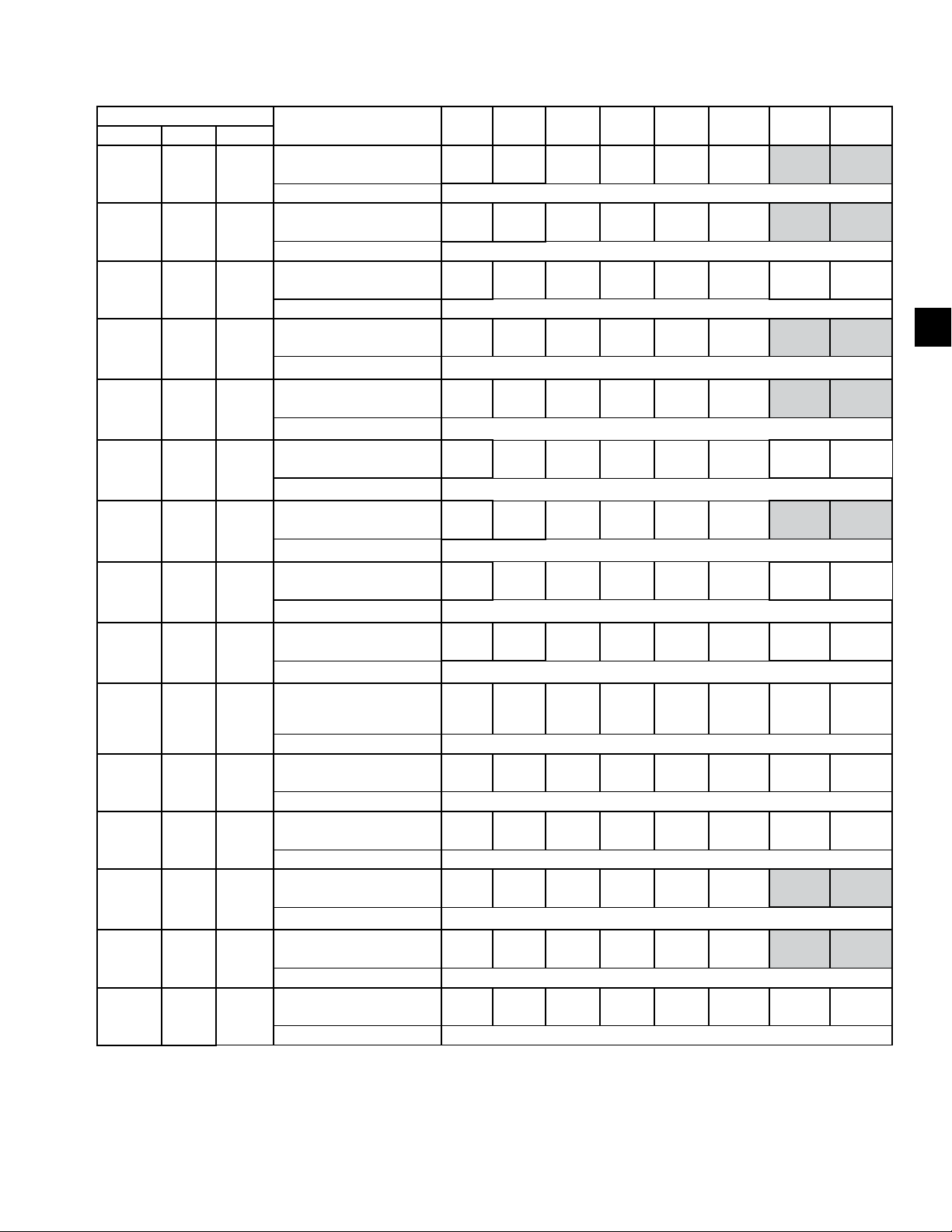
FORM QTC4-NM1
ISSUE DATE: 4/2/2018
TABLE 10 - ISOLATOR SELECTION AND MOUNTING LOCATIONS (CONT'D)
QTC4 CONFIGURATION
MODEL COND EVAP
340 S E
340 H E
370 P J
370 S F
370 H J
400 P J
405 S H
410 H H
410 P J
DESCRIPTION 9 10 11 12 13 14 15 16
Isolator X-Dimension
Isolator Y-Dimension 87 (2206)
Isolator X-Dimension
Isolator Y-Dimension 87 (2206)
Isolator X-Dimension
Isolator Y-Dimension 87 (2206)
Isolator X-Dimension
Isolator Y-Dimension 87 (2206)
Isolator X-Dimension
Isolator Y-Dimension 87 (2206)
Isolator X-Dimension
Isolator Y-Dimension 87 (2206)
Isolator X-Dimension
Isolator Y-Dimension 87 (2206)
Isolator X-Dimension
Isolator Y-Dimension 87 (2206)
Isolator X-Dimension
Isolator Y-Dimension 87 (2206)
10
(263)
10
(263)
10
(263)
10
(263)
10
(263)
10
(263)
10
(263)
10
(254)
10
(260)
81
(2057)
81
(2057)
81
(2057)
81
(2057)
81
(2057)
81
(2057)
81
(2057)
81
(2057)
81
(2054)
161
(4084)
161
(4084)
145
(3680)
145
(3680)
145
(3680)
145
(3680)
145
(3680)
145
(3680)
145
(3677)
201
(5105)
201
(5105)
205
(5219)
206
(5219)
206
(5219)
206
(5219)
205
(5219)
206
(5219)
205
(5216)
298
(7582)
298
(7582)
284
(7218)
284
(7218)
284
(7218)
284
(7218)
284
(7218)
284
(7218)
284
(7215)
SECTION 5 - TECHNICAL DATA
383
(9726)
427
(10843)
383
(9725)
427
(10842)
427
(10842)
427
(10842)
427
(10843)
427
(10842)
427
(10839)
439
(11157)
483
(12274)
483
(12274)
505
(12817)
495
(12577)
539
(13694)
539
(13694)
562
(14262)
5
450 S G
490 H J
460 S G
470 C K
480 C J
500 S J
NOTES:
1. Contact your nearest Quantech Sales Representative for weight data.
2. All isolator mounting holes are 19mm.
3. Dimensions are in inches (mm).
Isolator X-Dimension
Isolator Y-Dimension 87 (2206)
Isolator X-Dimension
Isolator Y-Dimension 87 (2206)
Isolator X-Dimension
Isolator Y-Dimension 87 (2206)
Isolator X-Dimension
Isolator Y-Dimension 87 (2206)
Isolator X-Dimension
Isolator Y-Dimension 87 (2206)
Isolator X-Dimension
Isolator Y-Dimension 87 (2206)
10
(263)
10
(263)
10
(263)
10
(263)
10
(263)
10
(263)
81
(2057)
81
(2057)
81
(2057)
81
(2057)
81
(2057)
81
(2057)
154
(3907)
154
(3907)
154
(3907)
154
(3907)
154
(2908)
154
(3907)
206
(5219)
206
(5219)
206
(5219)
205
(5219)
205
(5219)
206
(5219)
284
(7218)
284
(7218)
284
(7218)
284
(7218)
284
(7218)
284
(7218)
427
(10842)
427
(10842)
427
(10842)
427
(10842)
427
(10843)
427
(10842)
483
(12274)
505
(12820)
505
(12820)
505
(12820)
539
(13694)
562
(14265)
562
(14265)
562
(14265)
QUANTECH
83
Page 84
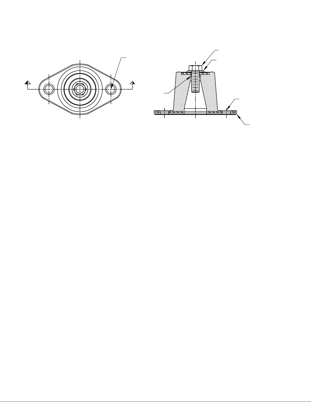
SECTION 5 - TECHNICAL DATA
SECTIOND-D
ELASTOMERIC ISOLATOR INSTALLATION
(B)
FORM QTC4-NM1
ISSUE DATE: 4/2/2018
TOP BOLT
TOP WASHER
D
C
L
D
Read the following instructions before beginning
installation.
1. Isolators are shipped fully assembled and are to be
positioned in accordance with the submittal drawings or as otherwise recommended.
2. Set isolators on oor, housekeeping pad or subbase, ensuring that all isolators lines match the
equipment mounting holes. The VMC group recommends that the isolator base (A) be installed
on a level surface. Shim or grout as required,
leveling all isolator bases to the same elevation
(0.03125-inch maximum difference is tolerated).
(C)
(B)
C
L
SECTION D-D
(A)
LD13762C
3. Bolt or anchor all isolators to supporting structure
utilizing base thru holes (B).
4. Remove top bolt and top washer. Place equipment on top of isolators so that mounting holes in
equipment or base line up with threaded hole (C).
5. Reinstall top bolt and washer and tighten down.
84
QUANTECH
Page 85
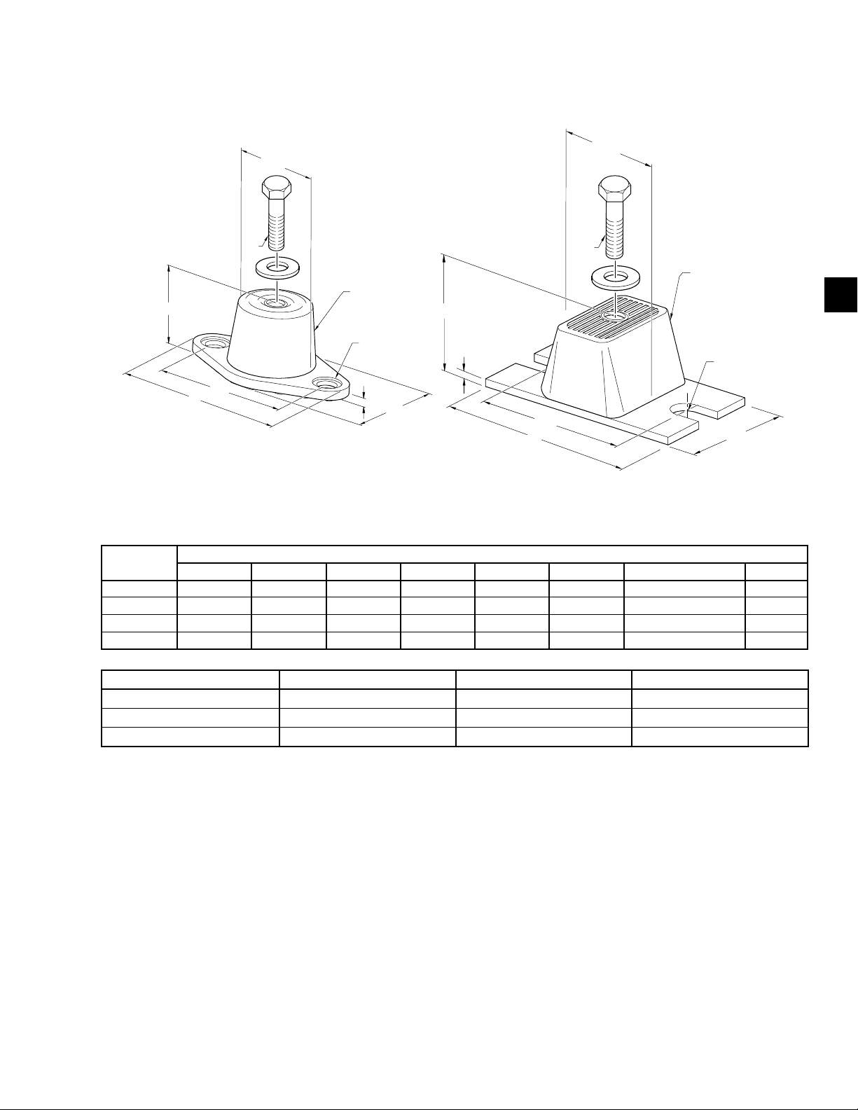
FORM QTC4-NM1
LD17304
ISSUE DATE: 4/2/2018
SECTION 5 - TECHNICAL DATA
ELASTOMERIC ISOLATOR SPECIFICATIONS
HF
DW
CD
MOLDED
DURULENE
HF
Ø = AD Thru
Typ 2 Places
AL
L
BT
W
BT
AL
L
DW
CD
MOLDED
DURULENE
5
R = 0.280 Slot
Typ 2 Places
W
MOUNT
TYPE
L W HF AL AD BT CD DW
DIMENSION DATA (INCHES)
RD1-WR 3.13 1.75 1.25 2.38 0.34 0.19 5/16-18 UNC X 3/4 1.25
RD2-WR 3.88 2.38 1.75 3.00 0.34 0.22 3/8-16 UNC X 1 1.75
RD3-WR 5.50 3.38 2.88 4.13 0.56 0.25 1/2-13 UNC X 1 2.50
RD4-WR 6.25 4.63 2.75 5.00 0.56 0.38 1/2-13 UNC X 1 3.00
MODEL NUMBER ISOLATOR COLOR WEIGHT RANGE (LBS) WEIGHT RANGE (KGS)
RD-3-CHARCOAL-WR CHARCOAL Up thru 825 UP TO 374
RD-4-BRICK RED-WR BRICK RED 826 thru 1688 375 - 766
RD-4-CHARCOAL-WR CHARCOAL 1689 thru 4000 767 - 1814
QUANTECH
85
Page 86
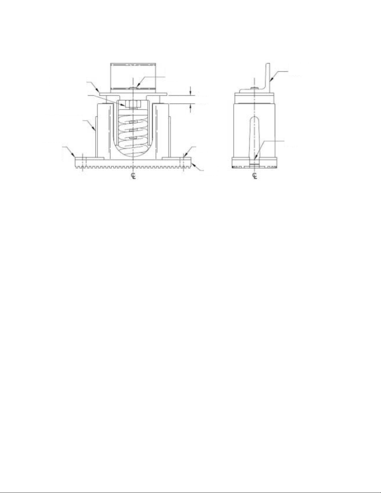
SECTION 5 - TECHNICAL DATA
FORM QTC4-NM1
ISSUE DATE: 4/2/2018
ONE INCH DEFLECTION ISOLATOR INSTALLATION
UPPER
HOUSING
(D)
LOWER
HOUSING
NON-SKID
ELASTOMERIC
PA D
POSITIONING
PIN (H)
0.25” min - 0.5” max
Read the following instructions before beginning
installation.
1. Isolators are shipped fully assembled and are to be
positioned in accordance with the submittal drawings or as otherwise recommended.
EQUIPMENT
BASE
(C)
(C)
(B)
4. Place equipment on top of isolators making sure
that mounting holes of the equipment line up with
isolator positioning pin (“H”).
5. Equipment or machine is at its full operating
weight.
2. Set isolators on oor, housekeeping pad or subbase, ensuring that all isolators centerlines
match the equipment mounting holes. The VMC
group recommends that the isolator base (“B”)
be installed on a level surface. Shim or grout as
required, leveling all isolator bases to the same
elevation (0.25-inch maximum difference can be
tolerated).
3. Bolt or anchor all isolators to supporting structure
utilizing base slotted holes (“C”).
6. Adjust each isolator in sequence by turning
spring adjusting bolt (“D”) one full counterclockwise turn at a time. Repeat this procedure on all
isolators, one at a time.
7. Continue adjusting each isolator until a minimum
of 0.25” clearance is achieved between the lower housing and upper housing. (See illustration
above).
8. Fine adjust isolators to level equipment.
86
QUANTECH
Page 87
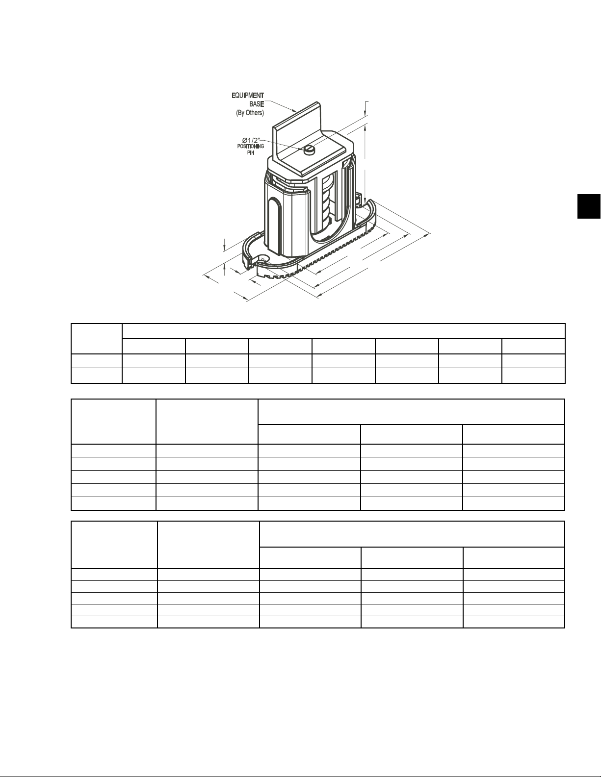
FORM QTC4-NM1
ISSUE DATE: 4/2/2018
SECTION 5 - TECHNICAL DATA
ONE INCH DEFLECTION SPRING ISOLATOR SPECIFICATIONS
CPX-X-
5
MOUNT
TYPE
DIMENSION DATA (INCHES)
W D L B C T H
CP 3 5/8 7-3/4 6-1/2 4-3/4 1/2 5-5/8
C2P 3 5/8 10-1/2 9-1/4 7-3/4 9/16 6
RATED CAPACITY (FOR UNITS WITH ALL LOAD POINTS
MODEL NUMBER COLOR CODE
LESS THAN 1785 LBS (810 KG)
(LBS.) (KG) PART NUMBER
CP-1D-510 BLACK Up thru 434 Up thru 197 029-25334-002
CP-1D-900 DARK GREEN 435 thru 765 198 thru 347 029-25334-003
CP-1D-1200 GRAY 766 thru 1020 348 thru 463 029-25334-004
CP-1D-1360 WHITE 1021 thru 1156 464 thru 524 029-25334-005
CP-1D-1785N GRAY/RED 1157 thru 1785 525 thru 810 029-25334-006
RATED CAPACITY (FOR UNITS WITH ANY LOAD POINT
MODEL NUMBER COLOR CODE
ABOVE 1518 LBS (689 KG)
(LBS.) (KG) PART NUMBER
C2P-1D-1350 DARK PURPLE Up thru 1148 Up to 521 029-25334-008
C2P-1D-1800 DARK GREEN 1149 thru 1530 522 - 694 029-25334-009
C2P-1D-2400 GRAY 1531 thru 2040 695 - 925 029-25334-010
C2P-1D-2720 WHITE 2041 thru 2312 926 - 1049 029-25334-012
C2P-1D-3570N GRAY/RED 2313 thru 3570 1050 - 1619 029-25334-013
NOTES:
1. Use either all CP's or all CP2's at all locations on a unit.
2. Installation requires bolting or anchoring mount to support structure with a 2 x 0.625" diameter bolts or 2 x 0.5" diameter concrete anchors.
3. All springs are designed for 50% over-travel.
QUANTECH
87
Page 88
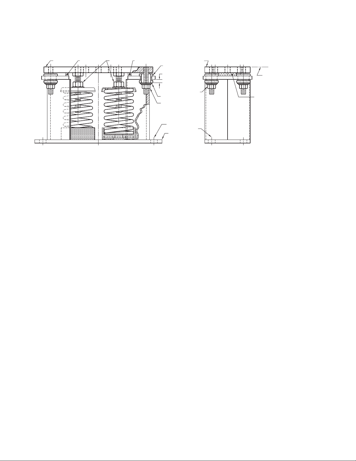
SECTION 5 - TECHNICAL DATA
TWO INCH DEFLECTION ISOLATOR INSTALLATION AND ADJUSTMENT
FORM QTC4-NM1
ISSUE DATE: 4/2/2018
("A")
("E")
("G")
C
L
("E")
Read the following instructions before beginning
installation.
1. Isolators are shipped fully assembled and are to be
positioned in accordance with the submittal drawings or as otherwise recommended.
2. Set isolators on oor, housekeeping pad, or sub-
base, ensuring that all isolator centerlines match
the equipment mounting holes. The VMC group
recommends that the isolator base plates (“B”)
be installed on a level surface. Shim or grout as
required, levelling all isolator base plates to the
same elevation (0.25-inch maximum difference
can be tolerated).
GROMMET
1/4 - 3/8 GAP
WASHER
("F")
("C")
("B")
("A")
("F")
("C")
C
L
EQUIPMENT
("E")
Bolt equipment securely to top plate of isolator
using a minimum of 2 x 0.625" UNC A325
GRADE 5 SAE bolts or weld equipment or
bracket to the top plate (“A”) of isolator with a
minimum 0.375" fillet welds 2” long @ 3” O.C.
for a minimum total weld of 10”. (All sides of
equipment or bracket resting on top plate (“A”)
must be welded).
6. The adjustment process can only begin after the
equipment or machine is at its full operating
weight.
7. Back off each of the 4 limit stop lock nuts (“F”) on
the isolators 0.5”.
3. Bolt or anchor all isolators to supporting structure
utilizing base plate through holes (“C”) or weld
base plate to supporting structure with 0.375"
llet weld 2” long @ 4” on center around entire
base plate or as engineered for specic load and
or eld conditions.
4. Isolators are shipped to the job site with (2)
removable spacer shims (“E”) between the top
plate and the housing. These shims must be in
place when the equipment is positioned over the
isolators.
5. With all shims (“E”) in place, position equipment
on top of plate (“A”) of isolator.
88
8. Adjust each isolator in sequence by turning spring
adjusting nuts (“G”) one full clockwise turn at a
time. Repeat this procedure on all isolators, one
at a time. Check the limit stop lock nuts (“F”)
periodically to ensure that clearance between the
washer and rubber grommet is maintained. Stop
adjustment of isolator only when the top plate
(“A”) has risen just above the shim (“E”).
9. Remove all spacer shims (“E”).
10. Fine adjust isolators to level equipment.
11. Adjust all limit stop lock nuts (“F”) per isolator,
maintaining 0.25-to 0.375-inch gap. The limit
stop nuts must be kept at this gap to ensure uniform bolt loading during uplift (as the case when
equipment is drained).
QUANTECH
Page 89
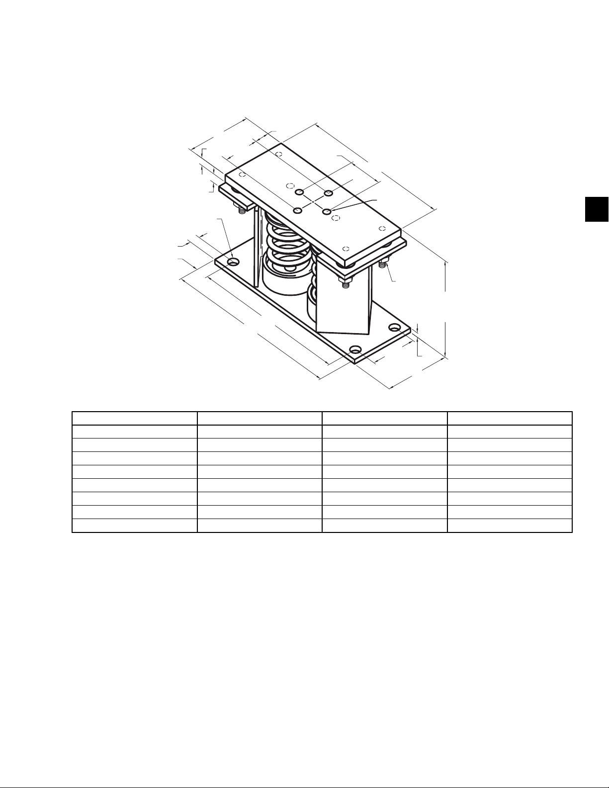
FORM QTC4-NM1
ISSUE DATE: 4/2/2018
TWO INCH DEFLECTION, RESTRAINED SPRING ISOLATOR SPECIFICATIONS
SECTION 5 - TECHNICAL DATA
Y2RS
12-1/4"
1-1/8"
2-3/4"
12"
5/8-11UNC
TYP. (4)
3-1/2"
1/2" LIMIT
STOP &
NUT
5"
8-3/8"
OPER.
HEIGHT
3/8"
3/4"
7/8"
3/8" GAP
Ø3/4"
TYP.(4)
5/8"
5"
2-3/4"
14"
MODEL NUMBER WEIGHT RANGE (LBS) WEIGHT RANGE (KGS) QUANTECH P/N
Y2RSI-2D-460 Up thru 391 UP TO 177 029-25336-006
Y2RSI-2D-710 392 thru 604 178 - 274 029-25336-008
Y2RSI-2D-870 605 thru 740 275 - 336 029-25336-009
Y2RSI-2D-1200N 741 thru 1020 337 - 463 029-25336-010
Y2RSI-2D-1690 1021 thru 1437 464 - 652 029-25336-011
Y2RSI-2D-2640N 1438 thru 2244 653 - 1018 029-25336-012
Y2RSI-2D-2870N 2245 thru 2618 1019 - 1188 029-25336-013
Y2RSI-2D-3280N 2619 thru 3740 1189 - 1696 029-25336-014
5
NOTES:
1. All dimensions are in inches, interpret as per ANSI Y14
2. Equipment must be bolted or welded to the top plate to meet allowable seismic ratings.
3. All springs are designed for 50% overload capacity with exception of the 029-25336-013 and 029-25336-014.
4. Contact your nearest Quantech Sales Representative for concrete installation.
QUANTECH
89
Page 90

FORM QTC4-NM1
ISSUE DATE: 03/07/2018
THIS PAGE INTENTIONALLY LEFT BLANK
90
QUANTECH
Page 91
FORM QTC4-NM1
ISSUE DATE: 4/2/2018
SECTION 6 - COMMISSIONING
PREPARATION
Commissioning of this unit should only
be carried out by Quantech Authorized
personnel.
Commissioning personnel should be thoroughly
familiar with the information contained in this document before starting the unit.
The following basic checks should be made with the
customer power to the unit switched OFF.
Proper electrical lock out and tag out
procedures must be followed.
Inspection
Correct System Refrigerant Charge
The charge on a system should always be checked
when operating for several minutes at full speed with
the system stable. Stable conditions are defined as
operation without fan cycling, economizer cycling, VI
solenoid cycling, or any other system transient conditions. Ideal refrigerant charge will be reached when the
refrigerant level in the evaporator is near the middle of
the evaporator sight glass.
Refrigerant should not be added or
removed unless the level is at the bottom
or the top of the glass. It is not necessary to
weigh charge unless the entire charge has
been lost. The ease of charging is possible
since the microchannel coils hold only a
small amount of refrigerant charge. A
charging valve is located between the xed
orice and the evaporator for adjusting
charge. Charge should be added as liquid
with the pump ON and liquid owing
through the evaporator.
6
Inspect unit for installation damage. If found, take
action and/or repair as appropriate.
Refrigerant Charge
Packaged units are normally shipped as standard with
a full refrigerant operating charge. Check that refrigerant pressure is present in both systems and that no
leaks are apparent. If no pressure is present, a leak test
must be undertaken, the leak(s) located and repaired.
Do not evacuate or liquid charge with static water in
the evaporator. Turn the pump on. Take care to liquid charge slowly to avoid excessive thermal stress
at the charging point and to assure the refrigerant
temperature in the evaporator does not go below the
freezing point with liquid refrigerant in the evaporator. Once the vacuum is broken, charge into the
evaporator or flash tank with the Condenser Drain
Valve (Flash Tank Feed) open and the chilled liquid
pump ON to the full operating charge, as detailed in
SECTION 5 - TECHNICAL DATA.
Service and Oil Line Valves
Open each compressor oil, economizer, and discharge
ball or service valves. If valves are of the back-seat
type, open them fully (counterclockwise) then close
one turn of the stem to ensure operating pressure is fed
to pressure transducers.
Compressor Oil
To add oil to a circuit - connect a hand oil pump
(Part No. 470-10654-000) to the 1/4" (6.35 mm) oil
charging valve on the oil separator piping with a length
of clean hose or copper line, but do not tighten the flare
nut. Using clean oil of the correct type (“L” oil), pump
oil until all air has been purged from the hose then
tighten the nut. Stroke the oil pump to add oil to the oil
system. While the compressor is running at full speed,
the oil level should be visible in the sight glass of the
oil separator. Approximately 2 to 3.1 gallons (7.5 to
11.6 liters) are present in each refrigerant system.
QUANTECH
91
Page 92
SECTION 6 - COMMISSIONING
FORM QTC4-NM1
ISSUE DATE: 4/2/2018
Avoid levels in either oil separator that are above
the middle of the top sight glass. This may cause
excessive oil carryover in the system. High oil concentration in the system may cause nuisance trips resulting
from incorrect readings on the level sensor and temperature sensors. Temperature sensor errors may result
in poor liquid control which will result in liquid overfeed and subsequently damage the compressor. High
oil carryover may also cause liquid to be returned to the
compressor, which can damage the compressor.
Fans
Check that all fans are free to rotate and are not damaged. Ensure blades are at the same height when
rotated. Ensure fan guards are securely fixed.
If condenser fans are manually operated
in VFD mode, manually turn on all 4 fan
digital outputs before enabling fan control
voltage output. Damage to a fan contactor
or fan VFD may occur if this instruction
is not followed.
plugged air vent mounted on the top of the evaporator
body.
Flow rates and pressure drops must be within the limits
given in SECTION 5 - TECHNICAL DATA. Operation
outside of these limits is undesirable and could cause
damage.
If main power must be switched OFF for maintenance
or shutdown, precautions must be taken. See Unit
Maintenance and Shutdown in Sub-freezing Conditions
on Page 94. Before placing the unit back in service,
valves should be opened and power must be switched
on (if power is removed for more than 8 hours) for at
least 8 hours (24 hours if ambient temperature is below
86°F [30°C]) before the unit is restarted.
Flow Switch
Verify a chilled water flow switch is correctly fitted
in the customer’s piping on the evaporator outlet, and
wired into the control panel correctly using shielded
cable.
Isolation / Protection
Verify all sources of electrical supply to the unit are
taken from a single point of isolation. Check that the
maximum fuse sizes recommended in SECTION 5 -
TECHNICAL DATA has not been exceeded.
Control Panel
Check the panel to see that it is free of foreign materials (wire, metal chips, etc.) and clean out if required.
Power Connections
Check that the customer power cables are connected
correctly to the terminal blocks or optional circuit
breaker. Ensure that connections of power cables within
the panels to the circuit breaker or terminal blocks are
tight.
Grounding
Verify that the unit’s protective ground terminal(s) are
properly connected to a suitable grounding point. Ensure that all unit internal ground connections are tight.
Water System
Verify the chilled liquid system has been installed correctly, and has been commissioned with the correct direction of water flow through the evaporator. The inlet
should be at the bottom connection on a two pass evaporator. Purge air from the top of the evaporator using the
There should be a straight run of at least five pipe diameters on either side of the flow switch. The flow switch
should be connected to Terminals 2 and 13 in the panel.
Temperature Sensor(s)
Ensure the leaving liquid temperature sensor is coated
with heat conductive compound (Part No. 013-00890-
000) and is inserted to the bottom of the water outlet sensor well in the evaporator. This sensor is part
of the pump control freeze protection operation. It
provides some freeze protection and must always be fully
inserted in the water outlet sensor well.
Programmed Options
Verify that the options factory-programmed into the
Micro Panel are in accordance with the customer’s
order requirements by pressing the OPTIONS key on
the keypad and reading the settings from the display.
Programmed Settings
Ensure the system cutout and operational settings are in
accordance with the operating requirements by pressing the PROGRAM key.
Date and Time
Program the date and time by first ensuring that the CLK
jumper JP2 on the Chiller Control Board is in the ON
position. Then press the DATE/TIME key and set the
date and time (See Date/Time and Schedule Keys on
92
QUANTECH
Page 93
FORM QTC4-NM1
ISSUE DATE: 4/2/2018
SECTION 6 - COMMISSIONING
Page 140 for more details on programming the date
and time).
Start/Stop Schedule
Program the daily and holiday start/stop by pressing
the SCHEDULE key (See Date/Time and Schedule
Keys on Page 140 for more details on programming
the date and time).
Setpoint and Remote Offset
Set the required leaving chilled liquid temperature
setpoint and Control Range under the SETPOINTS key.
The chilled liquid temperature control settings need to
be set according to the required operating conditions.
If remote temperature reset (offset) is to be used, the
maximum reset required must be programmed by
pressing the SETPOINTS key (See Setpoints Key on
Page 132).
FIRST TIME START UP
During the commissioning period there
should be sufficient heat load to run
the unit under stable full load operation
to enable the unit controls, and system
operation to be set up correctly, and a
commissioning log taken.
and display the nature of the fault.
Oil Pressure
When a compressor starts, press the relevant “System
Pressures” key and verify that oil differential pressure
(oil pressure-suction pressure) develops immediately.
If oil pressure does not develop, the automatic controls will shut down the compressor. Under no circumstances should a restart attempt be made on a compressor, which does not develop oil pressure immediately.
Switch the UNIT switch to the OFF position.
Loading
Once the unit has been started, all operations are fully
automatic. After an initial period at minimum capacity,
the control system will adjust the unit load depending
on the chilled liquid temperature and rate of temperature change. If a high heat load is present, the controller will increase the speed of the compressor(s).
Condenser and Fan Rotation
Once a compressor is running, discharge pressure
rises as refrigerant is pumped into the air-cooled condenser coils. This pressure is controlled by stages of
fans to ensure maximum unit efficiency while maintaining sufficient pressure for correct operation of the
condensers and the lubrication system.
6
Interlocks
Verify that liquid is flowing through the evaporator
and that heat load is present. Ensure that any remote
run interlocks are in the run position and that the Daily
Schedule requires the unit to run or is overridden.
Unit Switch
Place the UNIT switch on the keypad to the ON position.
Startup
Press the SYSTEM SWITCHES key and place the
system switch for System 1 to the ON position. There
may be a few seconds delay before the first compressor starts because of the anti-recycle timer). Be ready
when each compressor starts, to switch the UNIT
switch OFF immediately, if any unusual noises or
other adverse conditions develop.
When a compressor is running, the controller monitors
oil pressure, motor current, and various other system
parameters such as discharge pressure, chilled liquid
temperature, etc. Should any problems occur; the control system will immediately take appropriate action
As discharge pressure rises, the condenser fans operate
in stages or ramp up in speed to control the pressure.
Verify that the fans operate in the correct direction of
rotation and operation is correct for the type of unit.
System Charge
Check system charge at steady full compressor load
only. It is important that all fans are running for the
system. The refrigerant level in the evaporator should
be about in the middle of the sight glass. Unless
levels are at the bottom or the top of the sight glass,
they should not cause concern or require adding or
removing charge.
GENERAL OPERATION
After completion of the above checks for System 1,
switch OFF the SYS 1 switch on the keypad and repeat
the process for each subsequent system. When all run
correctly, stop the unit, switch all applicable switches
to the ‘ON’ position and restart the unit.
Assure all checks are completed in the Equipment
Pre - Startup and Startup Checklist. The chiller is then
ready to be placed into operation.
QUANTECH
93
Page 94
SECTION 6 - COMMISSIONING
FORM QTC4-NM1
ISSUE DATE: 4/2/2018
Operation in Sub-freezing Conditions
The QTC4 may be operated in sub-freezing conditions
if the following freeze protections are taken:
A. A suction service valve electric actuator is
installed. Chiller software will operate the
actuator in order to protect against freezing due to
evaporator refrigerant migration.
-or-
B. No suction service valve is installed but the water
circuit valves are kept open, there is continuous
power to the chiller and pump for chilled water
pump control, and the pump will operate and circulate water through the evaporator whenever
commanded by the chiller.
The above operation is only advised if
uninterrupted power can be ensured.
Unforeseen power interruptions can
damage the evaporator in a very short
time frame if the temperature falls below
freezing.
Unit Maintenance and Shutdown in Subfreezing Conditions
If the QTC4 is maintained or shut down and will be
subjected to sub-freezing conditions, it is critical to
protect against evaporator and waterbox freeze damage. Quantech recommends the following options (in
order of freeze protection level) be performed on each
circuit.
A. Glycol: Replace water with an appropriate water
to glycol concentration of antifreeze.
-or-
B. Drain: Remove power to the waterbox heaters.
Close the water valves, drain the evaporator, and
leave the evaporator drain valves open.
-or-
C. Refrigerant Valve - Off: Close the water valves,
close ash tank drain valves, close the suction
service valves and leave power to the chiller for
evaporator heater mat and waterbox heater operation. For units without a suction service valve,
close the discharge and compressor oil valves.
If there is potential for power loss, Quantech recommends the water in the chilled water circuit be replaced
with an appropriate water-to-glycol concentration.
Failure to follow Quantech freeze protection recommendations can void the
warranty.
-or-
D. Pump Control: Keep power to the chiller in or-
der to have control over chilled water pumps and
heater operation and leave the water circuit valves
open. This will enable water to circulate through
the evaporator to avoid freezing.
Options A and B are the recommended
processes for unit maintenance and
shutdown. Unforeseen power interruptions can damage the evaporator in a very
short time frame if the temperature falls
below freezing.
94
QUANTECH
Page 95

FORM QTC4-NM1
ISSUE DATE: 4/2/2018
SECTION 7 - OPERATION
OPERATING CONTROLS
DISPLAY
KEYPAD
FIGURE 17 - KEYBOARD AND DISPLAY
UNIT
SWITCH
LD21850
The keypad also contains keys in the center section for
data entry in the various program modes. These keys
are listed below:
• 0-9 Keys NUMERIC KEYPAD
• PERIOD/DECIMAL
• +/- PLUS/MINUS
• ENTER
• CANCEL
• ▲ UP ARROW
• ▼ DOWN ARROW
• ◄ LEFT ARROW
• ► RIGHT ARROW
The numeric keys allow keying numeric values into
memory.
The • (PERIOD/DECIMAL) key allows keying a
decimal point into numeric values.
7
Unit Switch
A double pole single throw ON/OFF rocker switch on
the front of the control panel is used to turn the entire
chiller ON and OFF. When the switch is placed in the
OFF position, the entire unit shuts down immediately
and all systems will be disabled. One pole of the UNIT
switch contacts is wired to the Run Signal input and the
Chiller Control Board “UNIT switch X” digital input
(X equals System 1 or 2). Separate System Fuses are
also wired in series with each set of UNIT switch contacts. If either fuse is pulled or blown, only the system
with the good fuse (Input is high) will run. When both
inputs are high, the entire chiller will be enabled to run.
When both inputs are low, the chiller will be disabled
as a UNIT switch OFF Shutdown.
Keypad
An operator keypad allows complete control of the system from a central location. The keypad offers a multitude of command keys on the left and right side of the
keypad to access displays, program setpoints, history
data, and initiate system commands. Most keys have
multiple displays that can be accessed by repetitively
pressing the key or by pressing the ▲,▼,◄, and ►
(ARROW) keys. The keypad utilizes an overlay to
convert the keypad to various languages.
The +/- (PLUS/MINUS) key allows making numeric
values negative.
The (ENTER) key stores program changes into
memory.
The X (CANCEL) key is used to cancel the data entry operation and returns the programmed value to the
original value, before any programming changes were
made, when an error is made.
The ▲ (UP ARROW) and ▼ (DOWN ARROW)
keys allow scrolling backward (▲) and forward (▼)
through items to be programmed under keys such as the
PROGRAM or OPTIONS key.
The ▲ (UP ARROW) and ▼ (DOWN ARROW)
keys also allow scrolling forward (▼) or backwards
(▲) through data display keys that have multiple
displays under keys such as UNIT DATA, SYSTEM
DATA, HISTORY, PROGRAM, OPTIONS, etc. The
arrow keys can be used instead of repeatedly pressing
the data key to see the multiple displays under a key.
Once the ▲ ▼ (ARROW) keys are pressed and used
for scrolling, pressing the original data key will return
to the first display message displayed under the data
(UNIT DATA, SYSTEM DATA, etc.) keys.
QUANTECH
95
Page 96

SECTION 7 - OPERATION
FORM QTC4-NM1
ISSUE DATE: 4/2/2018
The ◄ ► (LEFT and RIGHT ARROW) keys allow
scrolling between non-numeric program choices under
the OPTION, DATE/TIME, and SCHEDULE keys.
The ◄ (LEFT ARROW) key allows programming the
default value when programming numeric values. For
changing numeric values, the ► (RIGHT ARROW)
key has no function.
The ◄ ► (ARROW) keys also allow scrolling sideways between the same displays on different systems.
For example, pressing the ► (RIGHT ARROW) key
while viewing the system #1 suction pressure moves the
display to system #2 suction pressure.
Pressing the ◄ (LEFT ARROW) key moves the
opposite direction. The arrow keys also allow fast
scrolling through data under keys such as HISTORY
by enabling the operator to move between subgroups
of data such as Unit, System, and VSD data.
Keypad Data Entry Mode
For numeric programmable items, the data entry mode
is entered by pressing any of the number keys, the decimal point key, or the +/- key. When the data entry mode
is entered, the data from the key press will be entered
and the cursor will appear under the position where the
data is being entered.
For non-numeric programmable items, data entry
mode is entered by pressing the ◄ or ► (ARROW)
keys. When the data entry mode is entered, the cursor
will appear under the first position of the non-numeric
string. The programmable choice may be changed by
pressing the ◄ or ► (ARROW) keys.
To exit the data entry mode and store the programmed
value, the (ENTER) key must be pressed. When
the (ENTER) key is pressed, the cursor will disappear.
The data entry mode may also be exited by pressing
the X (CANCEL) key. The programmed data will be
returned to its original value when the X (CANCEL)
key is pressed.
When the data entry mode is exited, the cursor will disappear. If any other key is pressed while in the Data
Entry Mode, the following display will appear for 2
seconds indicating the user must choose between
accepting or canceling the change:
XXXXXXXXXXX PRESS TO ACCEPT VALUE OR
X TO CANCEL DATA ENTRY
If the (ENTER) key was pressed from the data entry mode and the numeric value entered was out of
range, the following message will appear for 2 seconds
followed by the original data display.
XXXXXXXXXXX OUT OF RANGE TRY AGAIN!
XXXXXXXXXXXXXXXXXXXXXXXXXXXXXXXXXXXX
Display
The 80 character (2 lines of 40 characters per line)
display is a Liquid Crystal Display (LCD) used for
displaying unit parameters, system parameters, and
operator messages. The display has an LED backlight
background for night viewing and is viewable in direct
sunlight.
Anti-recycle Timer
On power-up of the control panel, the anti-recycle timer for each system will be set to 120 seconds and must
time out before a compressor is allowed to start.
Whenever a system starts, the anti-recycle timer for all
systems will be set to 120 seconds and will count down
from the time the motor starts. The timer must time out
before another compressor is allowed to start.
Whenever a system shuts down, the anti-recycle timer
for that system will be set to 120 seconds. The timer
must time out before the system is allowed to restart.
Evaporator Pump Control
The evaporator pump dry contacts are energized when
any of the following conditions are true:
• If a Low Leaving Chilled Liquid Fault occurs.
• Whenever a compressor is running.
• The Daily Schedule is ON and the UNIT switch
is ON.
Even if one of above is true, the pump will not run if
the panel has been powered up for less than 30 seconds
or if the pump has run in the last 30 seconds to prevent
pump motor overheating.
Evaporator Heater Control
The evaporator heater is controlled by ambient
air temperature. If no systems are running and the
ambient temperature drops below 4.4 °C (40°F), the
heater is turned ON. If no systems are running and
the temperature rises above 7.2°C (45°F) the heater is
turned OFF. Whenever a system is running, the evaporator heater is turned OFF.
96
QUANTECH
Page 97

FORM QTC4-NM1
ISSUE DATE: 4/2/2018
SECTION 7 - OPERATION
Both evaporator heater outputs will always be turned
ON and OFF together. An under voltage condition will
keep the heater OFF until full voltage is restored to the
system.
Compressor Heater Control
Each compressor has its own heater. The purpose of
the heater is to assure refrigerant does not condense
in the compressor. There is no oil sump, but refrigerant could possibly condense in the rotors or the motor
housing. The heater will be OFF whenever the respective compressor is running. As soon as the compressor
shuts OFF, the heater will turn ON as long as all motor
temperature sensors in the compressor read less than
70°C (158°F). The heater will turn OFF, if any internal
compressor motor temperature sensor reads more than
71.1°C (160°F).
Alarms
Each system has its own alarm. The Alarm output is ON
(dry contact closed) when no fault condition is present and OFF (dry contact open) to indicate an alarm
situation. The Alarm will be activated (contacts open),
if any of the following are true.
• A System is faulted or inhibited from starting for
more than 5 seconds.
• The Unit is faulted or inhibited from starting for
more than 5 seconds.
• A System is locked out.
• The Unit is locked out.
• Power is removed from the chiller.
Chiller Run Contact
The Chiller Run dry contact is closed whenever any system is running. It is open when all systems are shut OFF.
Flow Switch Control
A chilled liquid flow switch of suitable type MUST
be connected between Terminals 2 and 13 of 1TB to
provide protection against loss of liquid flow, which
will cause evaporator freeze-up if the chiller is permitted to run.
Remote Run / Stop
A Remote Run/Stop input is available for each system.
BASIC OPERATING SEQUENCE
Start Sequence and Loading
To initiate the start sequence of the chiller, the following conditions must be satisfied before the precharge
of the DC Bus will take place:
• UNIT SWITCH must be ON.
• At least one System Switch is ON
• Run permissive inputs (Remote Cycling
Contacts) must be closed.
• No unit faults exist.
• No unit start inhibits exist.
• At least one system not faulted or inhibited.
• The Daily Schedule is calling for the chiller to
run.
• The Flow Switch is closed.
• Leaving Chilled Liquid Setpoint is above the
Setpoint plus CR (Setpoint High Limit).
Once the precharge takes place, if the anti-recycle timer is timed out the chiller control system on the Chiller
Control Board will select the number of compressors
to start and begin operation of the compressors. The
compressor(s) speed will be ramped to the minimum
start frequency and increase speed as needed in an effort to regulate the leaving chilled liquid temperature
to meet the desired Setpoint. Unit Warnings
UNIT WARNING
Unit Warning Operation
Unit warnings are caused when a condition is present requiring operator intervention to restart the unit.
All setpoints, program values, and options should be
checked before operating the unit. Warnings are not
logged to the history buffer. If a unit warning is in
effect, the message will be displayed to the operator
when the STATUS key is pressed.
Low Battery Warning
The LOW BATTERY WARNING can only occur at
unit power-up. On micropanel power-up, the RTC battery is checked to see if it is still operational. If it is,
normal unit operation is allowed. If the battery voltage is determined to be low, the following warning
message is displayed indefinitely.
7
QUANTECH
UNIT WARNING: !! LOW BATTERY !!
CHECK SETPOINTS/PROGRAM/OPTIONS/TIME
97
Page 98

SECTION 7 - OPERATION
FORM QTC4-NM1
ISSUE DATE: 4/2/2018
If a low battery condition exists, all programmed
setpoints, program values, time, schedule, and history
buffers will have been lost. These values will all be
reset to their default values, which may not be the
desired operating values. Once a bad battery is detected, the unit will be prevented from running until the
MANUAL OVERRIDE key is pressed. Once the
MANUAL OVERRIDE key is pressed, the anti
recycle timers will be set to the programmed default anti
recycle time to allow the operator sufficient time to
check setpoints, program values, etc.
If a low battery is detected, it should be replaced as
soon as possible. The programmed values will all be
lost and the unit will be prevented from running on the
next power interruption.
MICROBOARD (331-03478-XXX)
The 331-03478-xxx microboard was developed as
a direct replacement for the 031-02478-xxx line of
microboards. No adapter harness is required when
replacing a 02478 with the new 03478. The 03478
microboard uses the IPUII processor card and provides
new features for the chillers, that the 02478 did not
have.
The 03478 program resides in flash memory instead
of EPROM. Program updates are accomplished by
loading the new program from an SD card inserted into
the SD card reader/writer. This same SD card reader/
writer also allows the user to datalog the operating
parameters to an SD card every 5 seconds. This
information is invaluable when troubleshooting
unit and system problems since it allows the service
technician to view operating parameters prior to a unit
fault.
Details on the new datalogging capability are explained
in the OPTIONS Key area of this manual. A Real Time
Clock/BRAM keeps time and setpoints during power
outages.
Refer to Figure 18 on Page 99, to locate the following ports of the 03478 microboard.
POWER – On solid indicates that the base board +12V
and +5V power supplies are operational.
TX1 – Red LED flashes when transmitting data out
Port 1 TB3 (Future native communications BAS port).
RX1 – Green LED flashes when receiving data in Port
1 TB3 (Future native communications BAS port).
TX2 – Red LED that flashes when transmitting data
out Port 2 (E-Link TB2 or printer TB1).
RX2 – Green LED that flashes when receiving data in
Port 2 (E-Link TB2 or printer TB1).
VSD_TX – Red LED that flashes when transmitting
data out Port 3 to the VSD Logic board.
VSD_RX – Green LED that flashes when receiving
data in Port 3 from the VSD Logic board.
Power Supply Test Points
24VAC power is applied to the 331-03478-xxx
microboard connector J12 and is used to create various DC power sources required by the microboard
circuitry. If the chiller control is malfunctioning,
the power supply test points should be measured to
determine the status of the microboard.
TP1 GND (Measure TP2, TP3, TP4 and TP5 in reference to this Test Point)
TP2 +3.3V [3.2 to 3.4VDC] provides power to the
processors
TP3 +5V [4.8 to 5.2VDC] power communication ports
2,3 and 4 and analog sensors
TP4 +12V [11.64 to 12.36VDC] powers the display
and backlight and is regulated to become the +5V
TP5 +15V [11.3 to 16.6VDC] powers the analog outputs to the EEV valves
Configuration Jumpers
The same configuration jumpers that existed on the
02478 are provided on the 03478.
Power Supplies and LEDs
The 03478 has LEDs to indicate various states of
operation of the microboard.
STATUS – Flashes every ½ second to indicate that the
base board processor is running its program.
98
JP4 Remote Temp Reset jumper position Pins 1 to 2
(left) = 4-20 mA, Pins 2 to 3 (right) = 0-10 VDC.
JP5 Remote Current Limit jumper position Pins 1 to 2
(left) = 4-20 mA, Pins 2 to 3 (right) = 0-10 VDC.
JP6 Remote Sound Limit jumper position (Pins 1 to 2
(left) = 4-20 mA, Pins 2 to 3 (right) = 0-10 VDC.
QUANTECH
Page 99
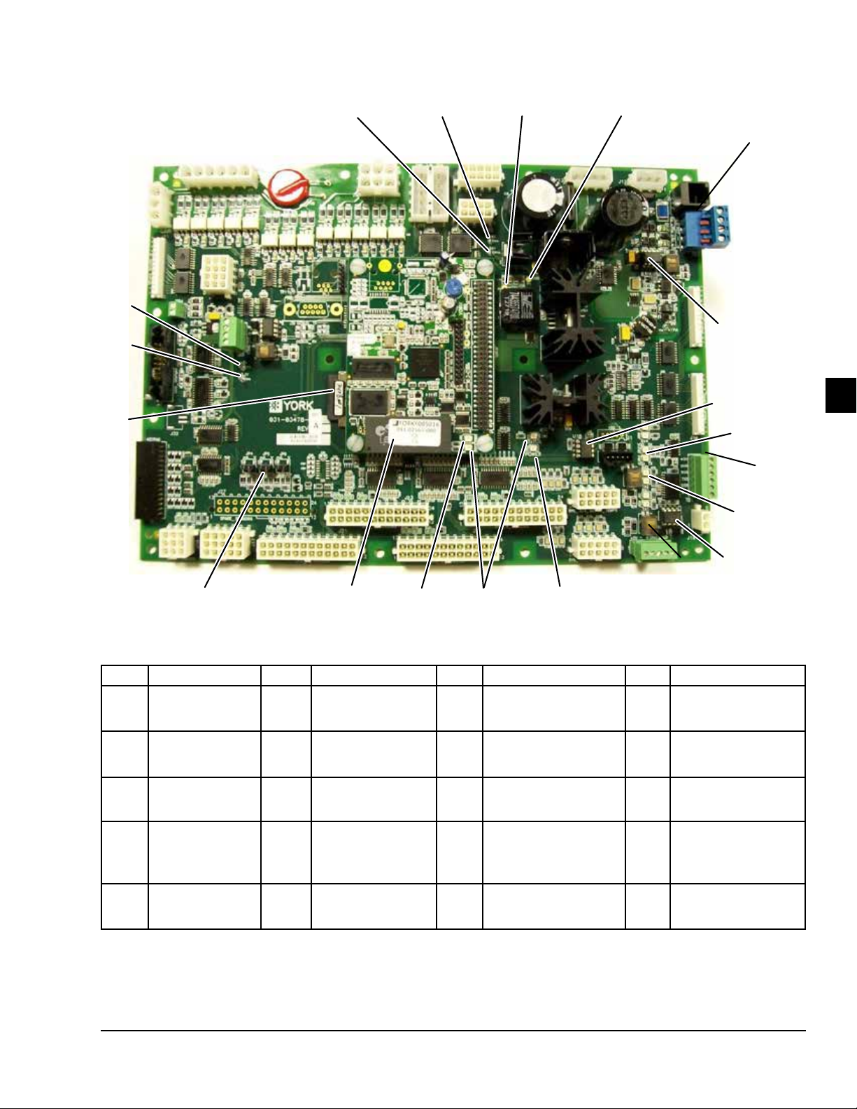
FORM QTC4-NM1
ISSUE DATE: 4/2/2018
SECTION 7 - OPERATION
20
19
18
17
16
1
15
2
14
7
3
13
12
11
10
4
ITEM DESCRIPTION ITEM DESCRIPTION ITEM DESCRIPTION ITEM DESCRIPTION
1
2
3
4
5
TP3 +5V
TP2 +3.3V
SD Card
JP4, JP5, JP6
Remote Setpoint
Jumpers
U5 RTC/BRAM
6
7
8
9
10
5
Power LED 11
Status LED 12
Power LED 13
Port 2
RS485 to E-Link/
SC-EQ or Modbus
U23 Port 2
RS-485 Driver
6
14
15
7
Port 2
RX2, TX2
PORT 2 RS-232
Printer or Modbus
VSD RX
VSD-TX
U18 VSD
RS-485 Driver
U26 PORT 1
RS-485 Driver
8
9
LD19331
16
17 TP1 GND
18 TP4+12V
19 TP5 + 15V
20 TP10 + 24V
Port 1
Native BAS
FIGURE 18 - NEW 331-03478-XXX MICROBOARD
QUANTECH
99
Page 100

SECTION 7 - OPERATION
FORM QTC4-NM1
ISSUE DATE: 4/2/2018
Communication Ports
The 03478 microboard has the following native
communication ports.
TB3 Port 1 Native BAS RS-485.
SW1 RS-485 Biasing Switch for Port. Set to ON if
Chiller is in an End Of Line position on the network.
U26 is the Port 1 RS-485 Driver Chip. It is
socketed to allow field replacement. RX1 and TX1
LEDs illuminate to indicate Port 1 communications
activity.
BUILDING AUTOMATION SYSTEM (BAS) COMMUNICATIONS
There are three different ways the chiller communicates to the BAS.
• Via board Native Communication protocol
• Using an E-Link Gateway
• Using an SC-EQ Communication Card
To access the Port communication parameters:
1. Press the PROGRAM key once.
2. Enter password 5255.
3. Press the (ENTER) key to display the Port 1
(P1) settings.
Set the following parameters:
1. DE Modier Address (number entered is
multiplied by 100): set as required by network.
2. DE Modier Offset (number entered is added to
DE Modier Address): set as required by network (see NOTE below).
3. P1 Protocol: set to BACNET (Default Setting).
4. P1 Manual MAC Address: set to 1
(Default Setting).
5. P1 Baud rate: set as required by network.
If not known, set to AUTO.
6. P1 Parity: set to NONE (Default Setting).
Using Communications Protocol
TB3 Port 1 Native BAS RS-485.
SW1 RS-485 Biasing Switch for Port. Set to ON if
chiller is in an End of Line position on the network.
U26 is the Port 1 RS-485 Driver Chip. It is socketed to allow field replacement. RX1 and TX1 LEDs
illuminate to indicate Port 1 communications activity.
QTC4 Native Communication Setup
Native communication is applicable to three types of
protocols, they are BACnet, N2 and Modbus RTU.
It requires IPU II Microboard (331-03478-101) and
software version Y.ACS.20.02 or later.
BACnet MS/TP Setup Port 1 (TB3)
To setup the BACNET MS/TP Port 1, follow the steps
below:
1. Connect the BACnet MS/TP Network to Port 1 on
the IPU II I/O Board.
2. Set up the QTC4 Port 1 (P1) for BACnet
Communications as shown in Figure 18 on Page
99.
7. P1 Stop Bits: set to 1 (Default Setting).
The BACnet DE Instance (Device Instance) is
determined by adding the [DE MODIFIER ADDRESS x 100] with the DE MODIFIER OFFSET. For
example, if the desired DE Instance address is 5023,
set the DE Modifier Address to 50, and then set the
DE Modifier Offset to 23 (50 X 100 + 23 = 5023).
DE Instances must be limited to values between
1 and 4,194,303 and every device in the network must
have a unique device Instance.
N2 Metasys Setup Port 1 (TB3)
1. Connect the N2 Network to Port 1 on the IPU II
I/O Board as shown in Figure 18 on Page 99.
2. Set up the QTC4 Port 1 (P1) for N2 Communications.
To access the Communication parameters:
You must always cycle power to the
microboard following port setting
changes.
100
QUANTECH
 Loading...