

Page 1
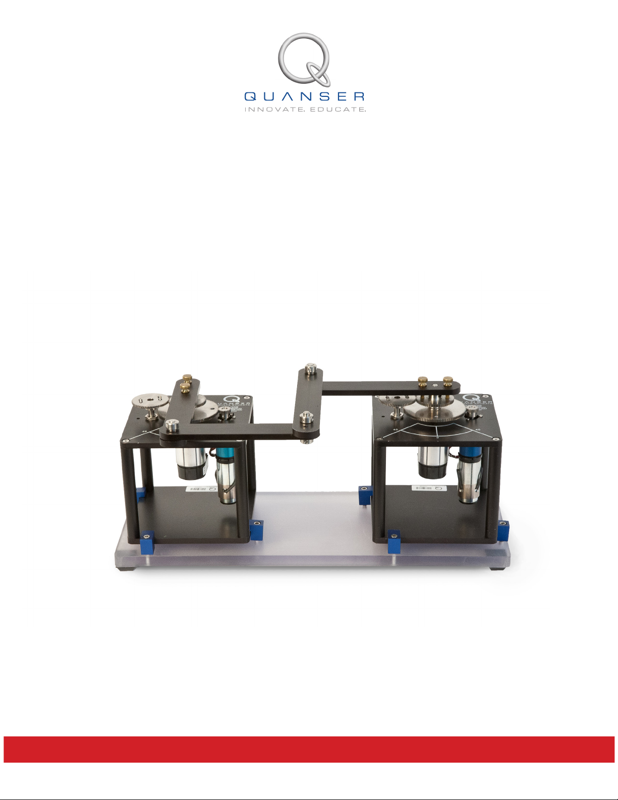
USER MANUAL
2 DOF Robot Experiment
Set Up and Configuration
CAPTIVATE. MOTIVATE. GRADUATE.
Page 2
c
电子信息产品污染控制管理办法 (中国 RoHS)
中国客户 Naonal Instruments 符合中国电子信息产品中限制使用某些有害物质命令 (RoHS)
。
关于Naonal Instruments 中国 RoHS合规性信息,请登录 ni.com/environment/rohs_china
(For informaon about China RoHS compliance, go to ni.com/environment/rohs_china)
2012 Quanser Inc., All rights reserved.
Quanser Inc.
119 Spy Court
Markham, Ontario
L3R 5H6
Canada
[email protected]
Phone: 1-905-940-3575
Fax: 1-905-940-3576
Printed in Markham, Ontario.
For more information on the solutions Quanser Inc. offers, please visit the web site at:
http://www.quanser.com
This document and the software described in it are provided subject to a license agreement. Neither the software nor this document may be
used or copied except as specified under the terms of that license agreement. All rights are reserved and no part may be reproduced, stored in
a retrieval system or transmitted in any form or by any means, electronic, mechanical, photocopying, recording, or otherwise, without the prior
written permission of Quanser Inc.
Waste Electrical and Electronic Equipment (WEEE)
This symbol indicates that waste products must be disposed of separately from municipal household waste, according to Directive
2002/96/EC of the European Parliament and the Council on waste electrical and electronic equipment (WEEE). All products at the
end of their life cycle must be sent to a WEEE collection and recycling center. Proper WEEE disposal reduces the environmental
impact and the risk to human health due to potentially hazardous substances used in such equipment. Your cooperation in proper
WEEE disposal will contribute to the effective usage of natural resources. For information about the available collection and
recycling scheme in a particular country, go to ni.com/citizenship/weee.
This product meets the essential requirements of applicable European Directives as follows:
• 2006/95/EC; Low-Voltage Directive (safety)
• 2004/108/EC; Electromagnetic Compatibility Directive (EMC)
2DROBOT User Manual 2
Page 3

CONTENTS
1 Presentation 4
1.1 Description 4
1.2 Experiment Overview 4
2 Components 5
3 Specifications 6
4 System Setup 7
5 Wiring Procedure 8
5.1 Cable Nomenclature 8
5.2 Typical Connections 9
6 Troubleshooting 12
7 Technical Support 12
2DROBOT User Manual
v 1.0
Page 4
1 PRESENTATION
1.1 Description
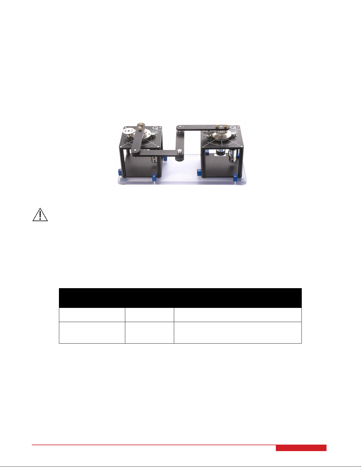
The Quanser 2 DOF Robot system, pictured in Figure 1.1, is a 2-DOF "pantograph" type robot. The goal, typically,
is to manipulate the X-Y position of a 4-bar linkage end effector. The system is planar and has 2 actuated and 3
unactuated revolute joints. Two servo motors mounted at a fixed distance control two arms coupled via two nonpowered two-link arms. Such a system is similar to the kinematic problems encountered in the control of larger
6-DOF robots including singularities.
Figure 1.1: 2 DOF Robot System
Caution: This equipment is designed to be used for educational and research purposes and is not intended
for use by the general public. The user is responsible to ensure that the equipment will be used by
technically qualified personnel only.
1.2 Experiment Overview
As described in Table 1.1, below, the 2 DOF Robot module by itself is supplied with two position control experiments.
However when combined with the 2 DOF Joint, additional experiments can be performed such as 2 DOF Gantry
and 2 DOF Inverted Pendulum.
Experiment Name Module Option
Needed
Joint Space Control 2 DOF Robot Design a joint-level position controller for each
Work Space Control 2 DOF Robot Design a task-space position controller that
Table 1.1: Possible experiments with the 2 DOF Robot and 2 DOF Joint modules.
Description
servo using a PID-type compensator.
controls the position of the end-effector to a desired point in the Cartesian X-Y plane.
2DROBOT User Manual 4
Page 5
2 COMPONENTS
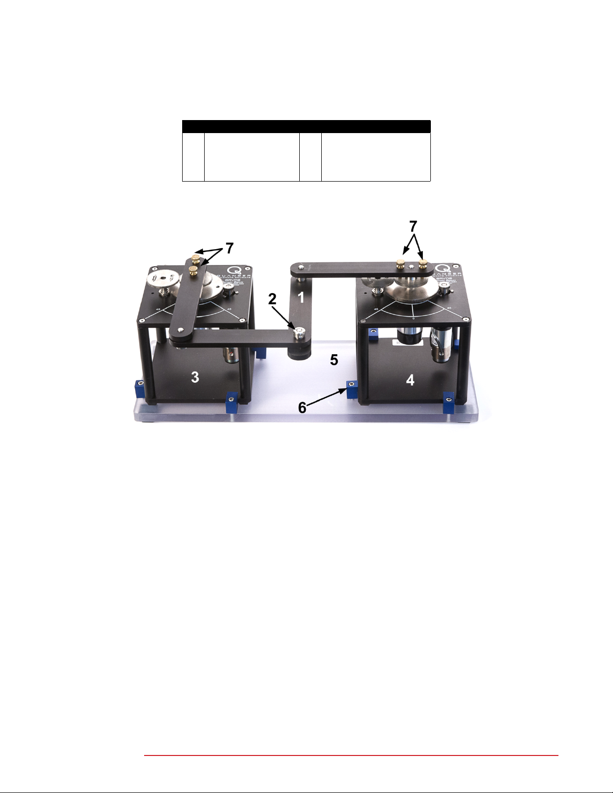
The components of the 2 DOF Robot system are listed in Table 2.1 and labeled in Figure 2.1, below
ID Component ID Component
1 Four-bar linkage 5 Support base plate
2 Robot end-effector 6 Servo clamp
3 SRV02 A 7 Linkage thumbscrews
4 SRV02 B
Table 2.1: 2 DOF Robot components.
Figure 2.1: 2 DOF Robot System
2DROBOT User Manual
v 1.0
Page 6

3 SPECIFICATIONS
Table 3.1, lists and characterizes the main parameters associated with the SRV02 2 DOF Robot module. Some of
these parameters are used in the mathematical model.
Symbol Description Value Unit
M
lk
M
b
L
b
J
b,og
J
b,piv
J
eq,linkage
J
eq
Mass of four-bar linkages 0.335 kg
Mass of single link 0.065 kg
Length of link 0.127 m
Link moment of inertia about cog. 8.74 × 10
Link moment of inertia about pivot. 4.41 × 10
Equivalent moment of inertia of 4-bar
1.49 × 10
−05
−04
−3
kg-m
kg-m
kg-m
linkage.
Equivalent moment of inertia of 4-bar
3.59 × 10
−3
kg-m
linkage including motor inertia.
2 DOF Robot Overall Dimensions 40 x 30 x 20 cm
2 DOF Robot Total Mass 4.0 kg
Table 3.1: 2 DOF Robot system specifications.
2
2
2
2
2DROBOT User Manual 6
Page 7
4 SYSTEM SETUP
Caution: If the equipment is used in a manner not specified by the manufacturer, the protection provided by
the equipment may be impaired.
Follow this procedure to setup the Quanser 2 DOF Robot module
for experimental use:
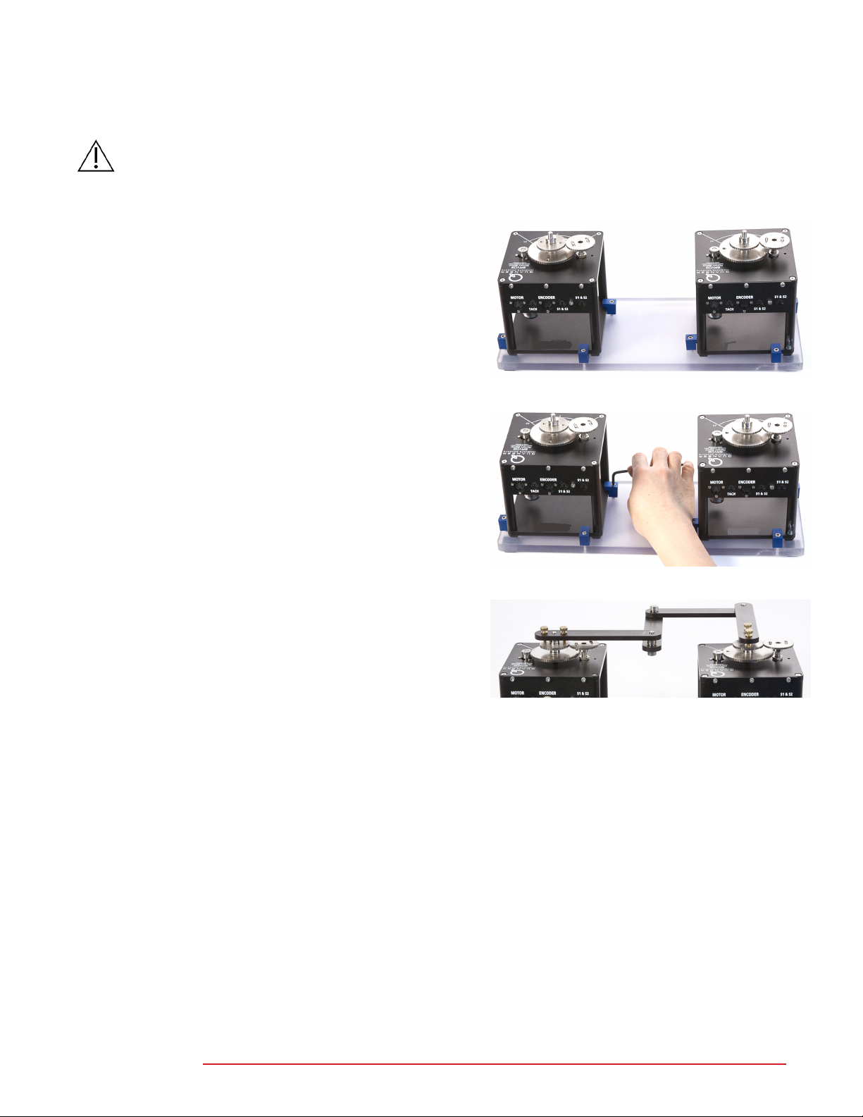
1. Place the two Rotary Servo Motor (SRV02) systems onto
the support plate, ID #5 in Figure 2.1, above, and as shown
in Figure 4.1a.
Note: Ensure the Rotary Servo Base Unit is setup in the
high gear configuration.
2. The support plate has a total of 8x clamps. Tighten the
screws of the 4x clamps on each servo until the SRV02 is
properly fastened to the base. You do not need to overly
tighten the clamps. See Figure 4.1b.
3. Mount the four-bar linkage on the load output shafts of both
SRV02 systems, as shown in Figure 4.1c. Make sure the
long side of the arm can be lined up the 0 degree marked
on the SRV02.
4. Tighten both thumbscrews, ID #7 in Figure 2.1, to fasten
the links onto the load shaft of the servo units.
5. Before running any experiments, it is recommended that
the base support plate be clamped down onto an edge of a
table. This prevents the chance of it falling over.
(a) SR02 on Mounting Plates
(b) Tighten clamps
(c) Mounting four-linkage bar
Figure 4.1: 2 DOF Robot System Setup
2DROBOT User Manual
v 1.0
Page 8
5 WIRING PROCEDURE
The following is a listing of the hardware components used in this experiment:
1. Power Amplifier: Quanser VoltPAQ-X2, 2x VoltPAQ-X1, or equivalent.
2. Data Acquisition Device: Q1-cRIO, Q2-USB, Q8-USB, QPID/QPIDe. NI DAQ Device, or equivalent.
3. Rotary Servo Plant: Quanser SRV02-ET.
4. Four-bar linkage module: Quanser 2 DOF Robot module.
See the references listed in Section 8 for more information on these components. The required cables are described
in Section 5.1 and the procedure to connect the above components is given in Section 5.2.
Caution: When Using the Quanser VoltPAQ power amplifier, make sure set the Gain to 1!
5.1 Cable Nomenclature
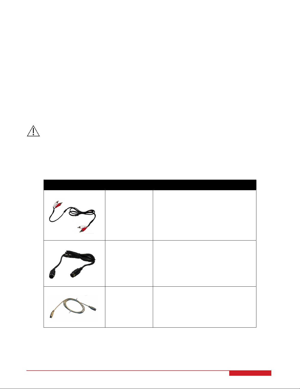
Table 5.1, below, provides a description of the standard cables used in the wiring of the SRV02 and 2 DOF Robot
system.
Cable Type Description
2xRCA to 2xRCA This cable connects an analog output of the
data acquisition (DAQ) device to the power
module for proper power amplification.
(a) RCA Cable
4-pin-DIN to 6-pinDIN
(b) Motor Cable
5-pin-stereo-DIN to
5-pin-stereo-DIN
(c) Encoder Cable
This cable connects the output of the power
module, after amplification, to the desired DC
motor on the servo.
This cable carries the encoder signals between an encoder connector and the data
acquisition (DAQ) device (to the encoder
counter). Namely, these signals are: +5 VDC
power supply, ground, channel A, and channel B
Table 5.1: Cables used to connect SRV02 to amplifier and DAQ device
2DROBOT User Manual 8
Page 9
5.2 Typical Connections
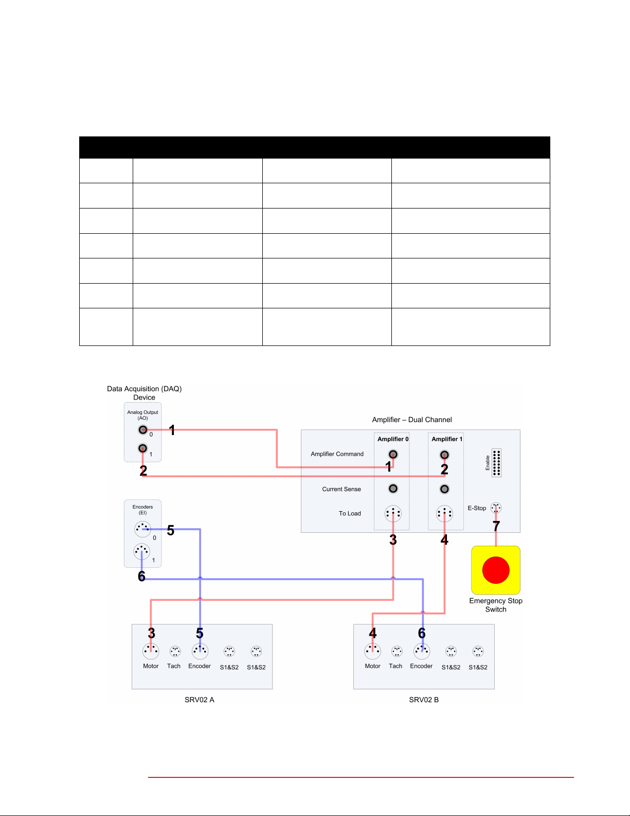
This section describes the typical connections used for to connect the SRV02 and 2 DOF Robot system to a data
acquisition (DAQ) device and a two-channel amplifier. The connections are given in Table 5.2 and illustrated in
Figure 5.3 and Figure 5.2. The detailed wiring procedure is given below.
Cable # From To Signal
1 Data acquisition (DAQ)
device:Analog Output #0
2 Data acquisition (DAQ)
device:Analog Output #1
3 Amplifier 0 "To Load" con-
nector
4 Amplifier 1 "To Load" con-
nector
5 Data acquisition (DAQ)
device:Encoder Input #0
6 Data acquisition (DAQ)
device:Encoder Input #1
7 Emergency Stop Switch E-Stop connector on Volt-
Table 5.2: Quanser 2 DOF Robot system wiring summary.
Amplifier Command #0
connector
Amplifier Command #1
connector
SRV02 A "Motor" connector
SRV02 B "Motor" connector
SRV02 A "Encoder" connector
SRV02 B "Encoder" connector
PAQ
Control signal to the amplifier
driving SRV02 A.
Control signal to the amplifier
driving SRV02 B.
Power leads to the DC motor of
SRV02 A.
Power leads to the DC motor of
SRV02 B.
SRV02 A encoder load shaft angle measurement.
SRV02 B encoder load shaft angle measurement.
The amplifier is deactivated
when the E-Stop switch is
pressed down
2DROBOT User Manual
Figure 5.1: 2D Robot connection diagram
v 1.0
Page 10
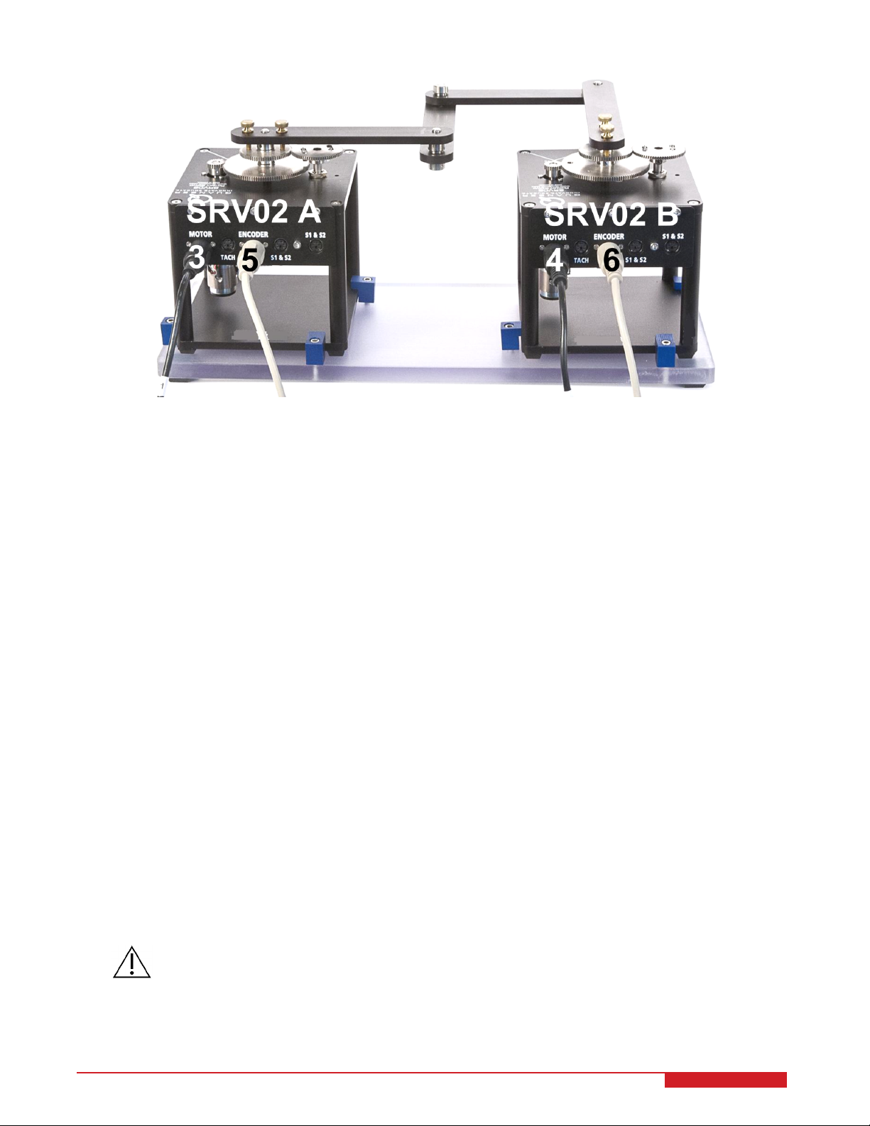
Figure 5.2: Connections on 2 DOF Robot plant.
The following steps describes a detailed wiring procedure of the 2 DOF Robot to the SRV02, data-acquisition board
and a dual channel power amplifier
1. It is assumed that the data acquisition (DAQ) device is already installed as discussed in its respective User
Manual.
2. Make sure everything is powered off before making any of these connections. This includes turning off your
PC and the amplifiers.
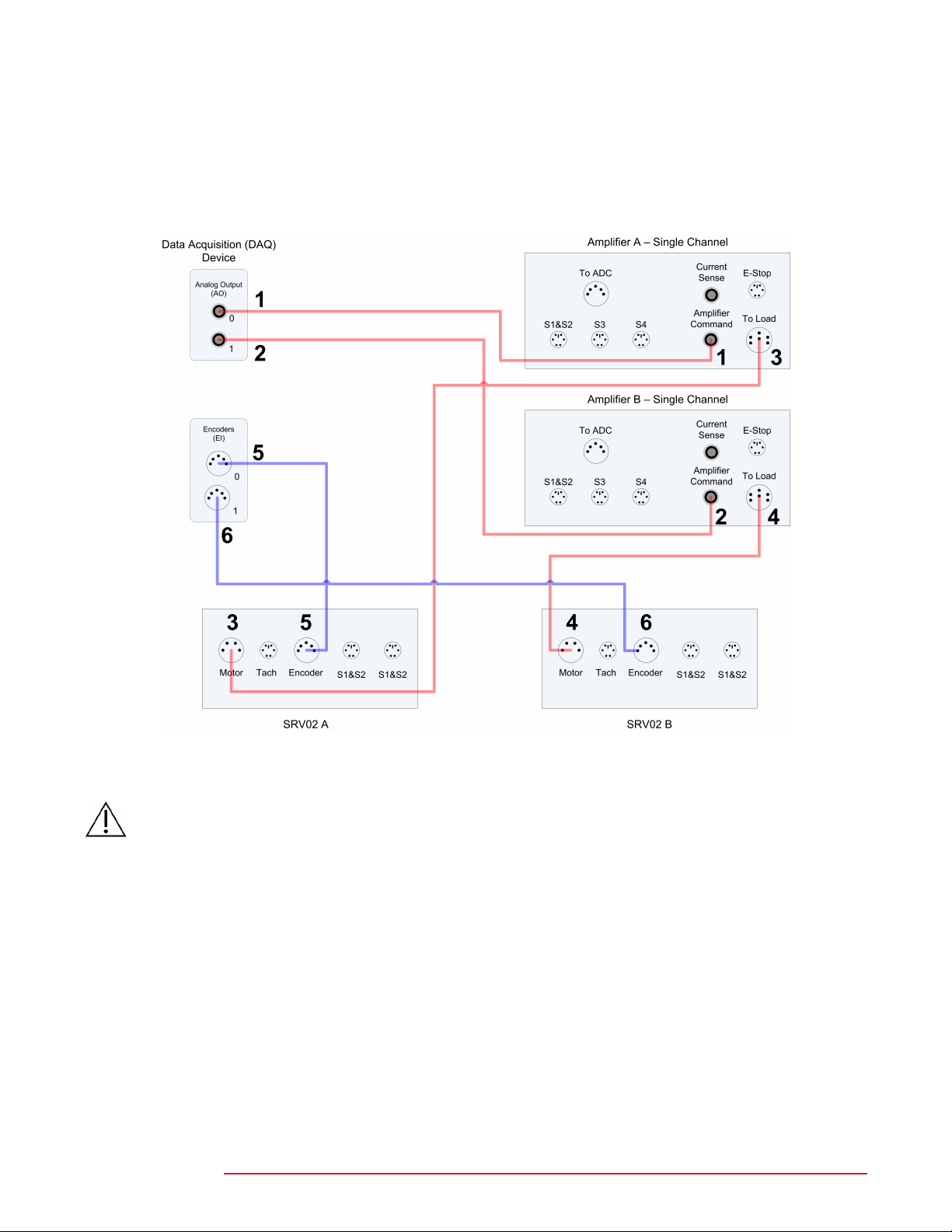
3. Connect one end of the 2xRCA to 2xRCA cable from the Analog Output Channel #0 on the data acquisition
(DAQ) device to the Amplifier Command 0 connector on the amplifier, that will be connected to SRV02 A (e.g.
red RCA connectors). See cable #1 shown in Figure 5.3. This carries the attenuated SRV02 A motor voltage
control signal, V
m,a/Ka,a
, where K
is the amplifier A gain.
a,a
4. Connect the one end of the 2xRCA to 2xRCA cable from the Analog Output Channel #1 on the data acquisition
(DAQ) device to the Amplifier Command 1 connector on the amplifier, that will be connected to SRV02 B (e.g.
white RCA connectors). See cable #2 shown in Figure 5.3. This carries the attenuated SRV02 B motor voltage
control signal, V
m,b/Ka,b
, where K
is the amplifier B gain.
a,b
5. Connect the 4-pin-stereo-DIN to 6-pin-stereo-DIN from To Load 0 on the amplifier to the Motor connector on
the SRV02. See connection #3 shown in Figure 5.3 and Figure 5.2. The cable transmits the amplified voltage
that is applied to the SRV02 A motor and is denoted V
m,a
.
6. Connect the 4-pin-stereo-DIN to 6-pin-stereo-DIN from To Load 1 on the amplifier to the Motor connector on
the SRV02. See connection #4 shown in Figure 5.3 and Figure 5.2. The cable transmits the amplified voltage
that is applied to the SRV02 B motor and is denoted V
m,b
.
7. Connect the 5-pin-stereo-DIN to 5-pin-stereo-DIN cable from the Encoder connector on the SRV02 A panel to
Encoder Input # 0 on the data acquisition (DAQ) device, as depicted by connection #5 in Figure 5.3 and Figure
5.2. This carries the SRV02 A load shaft angle measurement and is denoted by the variable θ
l,a
.
Caution: Any encoder should be directly connected to the Quanser data acquisition (DAQ) device (or equiv-
alent) using a standard 5-pin DIN cable. DO NOT connect the encoder cable to the amplifier!
8. Connect the 5-pin-stereo-DIN to 5-pin-stereo-DIN cable from the Encoder connector on the SRV02 B panel to
Encoder Input # 1 on the data acquisition (DAQ) device, as depicted by connection #6 in Figure 5.3 and Figure
5.2. This carries the SRV02 B load shaft angle measurement and is denoted by the variable θ
2DROBOT User Manual 10
l,b
.
Page 11
9. Connect the Emergency Stop Switch to the E-Stop connector on the VoltPAQ. This enable or disable the
command output on the amplifier.
5.2.1 Connections using a two Single Channel Amplifiers
Alternatively, this section shows the typical wiring of the 2 DOF robot when using 2x single channel power amplifier.
Figure 5.3: 2 DOF Robot connection diagram using two single channel amplifiers
Caution: When Using the Quanser VoltPAQ power amplifier, make sure set the Gain to 1!
2DROBOT User Manual
v 1.0
Page 12

6 TROUBLESHOOTING
The actuators and sensors of the 2 DOF Robot plant are all on the SRV02 units themselves. Therefore, see Reference [1] for any information regarding the testing and troubleshooting of the SRV02 devices.
7 TECHNICAL SUPPORT
To obtain support from Quanser, go to http://www.quanser.com/ and click on the Tech Support link. Fill in the form
with all the requested software and hardware information as well as a description of the problem encountered. Also,
make sure your e-mail address and telephone number are included. Submit the form and a technical support person
will contact you.
2DROBOT User Manual 12
Page 13

REFERENCES
[1] Quanser Inc. SRV02 User Manual, 2012.
2DROBOT User Manual
v 1.0
Page 14

 Loading...