

Page 1

This manual is based on the
GSP-1620 Satellite Data Modem.
Software or hardware changes may
have occurred after this printing.
QUALCOMM reserves the right to make changes in
hardware, software, and technical and product specifications
without prior notice.
QUALCOMM Incorporated
5775 Morehouse Drive
San Diego, CA. 92121-1714
U.S.A.
Copyright © 2001 QUALCOMM Incorporated.
All rights reserved. Printed in the United States of America.
This technology is controlled by the United States Government. Diversion contrary to U.S.
law prohibited.
QUALCOMM® is a registered trademark of QUALCOMM Incorporated.
Globalstar is a trademark of Loral QUALCOMM Satellite Services, Inc.
QUALCOMM Globalstar GSP-1620 Satellite Data Modem Integrator’s Reference Manual
80-99208-1, Rev. D
April 17, 2001
Page 2

TABLE OF CONTENTS
Who Should Use This Manual .................................................................. xvii
How This Manual Is Organized............................................................... xviii
Notational Conventions ............................................................................. xix
Abbreviations and Acronyms...................................................................... xx
Related Documentation............................................................................ xxiii
Cautions and Warnings ........................................................................... xxiv
Getting Started ........................................................................................1-1
GSP-1620 Modem Overview ...................................................................... 1-2
Typical Modem SCADA Applications ......................................1-3
Conceptual Overview ................................................................1-6
What’s in the Modem Integrator’s Kit?..................................................... 1-7
What You May Need in Addition to the Kit ............................1-9
Quick Bench Set-Up ...............................................................................2-1
Connecting Hardware Components........................................................... 2-2
A Quick Tour of the Modem .....................................................2-2
Connecting the Modem Cables .................................................2-4
Connecting the Modem Interface Cable ............................2-4
Connecting Antenna Cables ...............................................2-6
Connecting the Diagnostic Cable .......................................2-7
Connecting and Mounting the Antenna ..................................2-9
Mounting the Modem .............................................................2-11
Grounding the System ............................................................2-11
Providing Power to the Modem ............................................................... 2-12
Setting Up HyperTerminal to Talk to the Modem ................................. 2-15
Testing the Modem Setup ......................................................2-16
Resetting or Powering Off the Modem ..................................2-18
Where to Go Next ..................................................................................... 2-20
80-99208-1 Rev. D iii
Page 3

Integrator’s Reference Manual
Service-Programming Modems ...........................................................3-1
UTPST Overview........................................................................................ 3-2
Using the UTPST ....................................................................................... 3-2
Re-programming Default Parameters....................................................... 3-4
Bulk-Programming Modems...................................................................... 3-7
Upgrading Modem Software...................................................................... 3-7
Making Simple Data Calls ....................................................................4-1
Checking Modem Status............................................................................ 4-1
Making Simple Packet Data Calls ............................................................ 4-3
Making a Call from the Data Port ...........................................4-4
Entering Online-Command Mode ............................................4-5
Developing Modem Applications ........................................................5-1
Recommended Development Tools............................................................ 5-2
SCADA Application Components.............................................................. 5-2
Packet/Asynchronous Data Overview ....................................................... 5-4
Modem Application Scenarios ................................................................... 5-5
Working with Modem Features................................................................. 5-7
Using Data and Control Ports .................................................5-7
Data and Control Port Configurations ..............................5-8
Port Arbitration Behavior ..................................................5-9
AT Command Processing Modes ......................................5-12
Port(s) Affected by AT Commands ...................................5-13
Port Activation (DTR) Changes during Operation .........5-15
Port Use During Power On and Power Off ......................5-16
Globalstar Satellite Service ...................................................5-16
Short Messaging Service (SMS) .............................................5-17
SMS Alerts ........................................................................5-17
SMS Message Field Information ......................................5-18
SMS AT Commands ..........................................................5-18
Using SMS for Mobile-Terminated Calls ........................5-18
Globalstar Service Alerts .......................................................5-19
Service Status Message ..........................................................5-20
Position Location Determination ...........................................5-21
Using Packet Data ................................................................................... 5-21
Data Rate and Throughput ....................................................5-22
Networking Software and PPP Sessions ...............................5-22
Interoperability with Different Operating Systems .......5-22
iv 80-99208-1 Rev. D
Page 4

T able of Contents
IP Addressing for the GSP-1620 Modem ...............................5-23
Dynamic IP Addressing ....................................................5-23
Fixed IP Addressing .........................................................5-24
Finding IP Addresses ........................................................5-24
Virtual Private Network Service .....................................5-24
Dormant Mode Service ...........................................................5-25
Mobile-Originated Packet Data Calls ....................................5-27
Mobile-Terminated Packet Data Calls ..................................5-27
Answering Calls Using the Data Port Only ....................5-28
Answering Calls Using the Data and Control Ports .......5-29
Roaming and Packet Data Service ........................................5-29
Using Asynchronous Data ....................................................................... 5-30
Data Rate and Throughput ....................................................5-32
Mobile-Originated Asynchronous Data Calls ........................5-32
Mobile-Terminated Asynchronous Data Calls ......................5-33
Accessing Packet Data Over an Asynchronous
Connection ...............................................................................5-34
Roaming and Asynchronous Data Service ............................5-35
Typical Modem Initialization Strings ..................................................... 5-36
AT Command Reference ........................................................................6-1
AT Command Quick Reference Tables...................................................... 6-2
AT Commands Overview ........................................................................... 6-7
Command Alphabet ..................................................................6-7
Case Sensitivity ........................................................................6-7
Command Line Format ............................................................6-7
Command Syntax .....................................................................6-8
Basic AT Commands .................................................................................. 6-8
Results Returned ......................................................................6-9
Command Echo (E) ...................................................................6-9
Get Info (I) .................................................................................6-9
Monitor Speaker Loudness (L) ...............................................6-10
Monitor Speaker Mode (M) ....................................................6-11
Select Pulse Dialing (P) ..........................................................6-11
Result Code Suppression (Q) ..................................................6-12
Select Tone Dialing (T) ...........................................................6-13
DCE Response Format (V) .....................................................6-13
Result Code Selection Command (X) .....................................6-14
Reset to Default Configuration (Z) ........................................6-15
80-99208-1 Rev. D v
Page 5

Integrator’s Reference Manual
DCE Received Line Signal Detector Behavior (&C) .............6-16
DTE Data Terminal Ready Behavior (&D) ...........................6-16
Set to Factory-Defined Configuration (&F) ...........................6-17
Basic Action Commands .......................................................................... 6-18
Answer Incoming Call (A) ......................................................6-18
Repeat Last Command (A/) ....................................................6-19
Dial (D) ....................................................................................6-20
Hook Control (H) ....................................................................6-22
Return to Online Data Mode (O) ...........................................6-23
Basic S-Registers...................................................................................... 6-24
Results Returned ....................................................................6-24
Automatic Answer (S0) ...........................................................6-25
Command Line Termination Character (S3) ........................6-25
Response Formatting Character (S4) ....................................6-26
Command Line Editing Character (S5) .................................6-27
Pause Before Blind Dialing Time (S6) ...................................6-27
Connection Completion Timeout (S7) ....................................6-28
Comma Dial Modifier Time (S8) ............................................6-29
Carrier Detect Threshold Timeout (S9) .................................6-29
Carrier Loss to Disconnect Timeout (S10) ............................6-30
DTMF Tone Duration and Spacing (S11) ..............................6-31
Globalstar-Specific S-Register Extensions.............................................. 6-31
Silent Retry Timeout (S777) ..................................................6-31
Extended Configuration AT Commands ................................................. 6-32
Set Forward MUX Option (+CMUX) .....................................6-32
Set Rm Interface Protocol (+CRM) ........................................6-33
Get Modem User Terminal ESN (+GSN) ..............................6-34
Set Character Framing (+ICF) ..............................................6-35
Set Local Flow Control (+IFC) ...............................................6-36
Set Rm Interface Command Baud Rate (+IPR) ....................6-38
Online-Command Mode Commands........................................................ 6-40
Change from Online to Online-Command Mode (+++) .........6-40
Asynchronous Data through Gateway IWF Commands ........................ 6-41
Set Remote Config String (+CFG) .........................................6-41
Data Compression Control Command (+DS) ........................6-42
Error Control Selection Command (+ES) ..............................6-45
Modulation Selection Command (+MS) .................................6-47
vi 80-99208-1 Rev. D
Page 6

T able of Contents
Dormant Mode Commands ...................................................................... 6-48
Set Dormant Mode Timeout Value (+CTA) ...........................6-49
Packet No Dial ($QCPKND) ..................................................6-50
SMS Commands ....................................................................................... 6-51
SMS Move/Delete ($QCSMSM) ..............................................6-51
SMS Print ($QCSMSP) ..........................................................6-52
SMS Lock ($QCSMSL) ...........................................................6-56
SMS Alert ($QCSMSA) ..........................................................6-57
SMS Info ($QCSMSI) .............................................................6-58
Error Log Services Commands ................................................................ 6-59
Retrieve Error Log ($QCERR) ...............................................6-59
Clear Error Log ($QCCLR) ....................................................6-60
Service Status Commands....................................................................... 6-61
Service Alert ($QCSA) ............................................................6-61
Service Status ($QCSTATUS) ................................................6-62
Special Calls and Services Commands.................................................... 6-64
Time of Day ($QCTOD) ..........................................................6-64
Position Location Service ($QCPLS) .....................................6-66
Markov Statistics ($QCMSTATS) ..........................................6-68
Set Mode ($QCMODE) ...........................................................6-69
Protocol Stack Modification Commands ................................................. 6-70
TCP Stack Changes ($QCTCP) ..............................................6-70
Use Van Jacobsen Header Compression ($QCVJ) ................6-73
Integrating GSP-1620 Modems
into OEM Products .................................................................................7-1
Integrating Modems into Products............................................................ 7-2
Modem Mechanical Description ...............................................7-3
Modem Board Layout .........................................................7-3
Modem Dimensions and Weight ........................................7-6
Modem Antenna Connectors ....................................................7-6
Data and Control Ports ............................................................7-6
DTR/DSR Signal and Power On/Off ..................................7-7
Changing Data and Control Port Configuration ...............7-8
Control Port Signals ...........................................................7-8
Data Port Signals ................................................................7-9
DB-25 Data and Control Port Pinouts ...............................7-9
Diagnostic Port .......................................................................7-12
Diagnostic Port Pinouts ....................................................7-13
80-99208-1 Rev. D vii
Page 7

Integrator’s Reference Manual
DC Power ................................................................................7-15
Surge Protection ...............................................................7-16
EMI Filtering ....................................................................7-16
Power Consumption ..........................................................7-16
Power-On ...........................................................................7-17
Power-Off ..........................................................................7-18
Hard Power Reset .............................................................7-18
Grounding ...............................................................................7-18
Modem Mounting Guidelines .................................................7-19
QUALCOMM Mark on OEM Enclosures ........................7-20
Integrated Product Regulatory Labeling .........................7-21
Mounting Antennas On-Site.................................................................... 7-22
Modem Antenna Specifications ..............................................7-22
Antenna Dimensions and Weight ....................................7-23
Antenna Depiction ............................................................7-23
Antenna Cable Specifications ................................................7-25
Calculating Antenna Cable Length .......................................7-27
Mounting Antennas at the Field Site ....................................7-27
Finding a Good Antenna Location ...................................7-27
Securing Antenna Cables .................................................7-28
Mounting and Sealing Antennas on Flat Surfaces .........7-28
Mounting and Sealing Antennas on Poles ......................7-29
Mounting Multiple Antennas ...........................................7-29
Environmental Specifications.................................................................. 7-30
GSP-1620 Modem Environments ...........................................7-30
Temperature/Humidity ..........................................................7-30
Operational .......................................................................7-30
Non-Operational ...............................................................7-30
Thermal Radiation .................................................................7-31
Altitude ...................................................................................7-32
Operational .......................................................................7-32
Non-operational ................................................................7-32
Vibration .................................................................................7-32
Operational - Random ......................................................7-32
Non-Operational - Random ..............................................7-32
Operational - Sinusoidal ...................................................7-32
Non-Operational - Sinusoidal ..........................................7-32
viii 80-99208-1 Rev. D
Page 8

T able of Contents
Mechanical Shock ...................................................................7-34
Operational .......................................................................7-34
Non-Operational ...............................................................7-34
Acoustic Noise .........................................................................7-34
Digital Data Connector Durability ........................................7-34
Applied Forces ...................................................................7-34
Mating cycles .....................................................................7-34
RF Connector Durability ........................................................7-35
Materials .................................................................................7-35
Shipping ..................................................................................7-35
Dielectric Resonator Antenna (DRA) Environments.............................. 7-35
Temperature/Humidity ..........................................................7-35
Operational .......................................................................7-35
Non-Operational ...............................................................7-36
Thermal Radiation ..................................................................7-36
Icing/Freezing Rain/Snow ......................................................7-37
Altitude ....................................................................................7-37
Operational .......................................................................7-37
Non-Operational ...............................................................7-37
Vibration .................................................................................7-37
Operational - Random ......................................................7-37
Non-Operational - Random ..............................................7-37
Mechanical Shock ...................................................................7-38
Operational .......................................................................7-38
Non-Operational ...............................................................7-38
RF Connector Durability ........................................................7-39
Materials .................................................................................7-39
Shipping ..................................................................................7-39
Troubleshooting ......................................................................................8-1
Globalstar Background ........................................................................A-1
Space Segment........................................................................................... A-2
Ground Segment........................................................................................ A-2
Coverage .................................................................................................... A-2
Carriers...................................................................................................... A-4
Distributors and OEMs for User Terminals ............................................ A-5
80-99208-1 Rev. D ix
Page 9

Integrator’s Reference Manual
RF Certification/Restrictions .............................................................B-1
Certification............................................................................................... B-1
Federal Communications Commission (FCC) ........................B-2
European R&TTE Directive 1999/5/EC .................................. B-2
RF Restrictions.......................................................................................... B-3
Radio Astronomy Zones ........................................................... B-3
GPS Interference Elimination ................................................ B-3
Radio Frequency Exposure Restrictions .................................................. B-3
Electronic Device Restrictions.................................................................. B-4
Pacemakers .............................................................................. B-4
Hearing Aids ............................................................................ B-5
Other Medical Devices ............................................................. B-5
Warranty ..................................................................................................C-1
Product Support ....................................................................................D-1
QUALCOMM Globalstar Customer Service ............................................ D-1
Technical Support Information ............................................... D-1
Order Fulfillment Information ...............................................D-2
Website Information ................................................................D-3
Contacting QUALCOMM Customer Service ..........................D-3
Contact information ........................................................... D-4
Specification Summary ........................................................................ E-1
x 80-99208-1 Rev. D
Page 10

LIST OF FIGURES
Figure 1-1. Typical Modem SCADA Application Using
Packet Data ...................................................................1-4
Figure 1-2. Typical Modem SCADA Application Using
Asynchronous Data .......................................................1-5
Figure 1-3. Conceptual Diagram of GSP-1620 Modem ..................1-6
Figure 2-1. Simplified Top View of GSP-1620 Modem ...................2-3
Figure 2-2. Modem Interface Cable Bridle .....................................2-4
Figure 2-3. Modem Diagnostic Cable ..............................................2-8
Figure 2-4. Antenna Base Showing Connectors ...........................2-10
Figure 5-1. DCE - DTE Application Components ...........................5-3
Figure 5-2. DTE-to-DCE Rm Interface ...........................................5-7
Figure 5-3. Asynchronous Data Call Components .......................5-31
Figure 7-1. GSP-1620 Modem Board Layout (Top View) ...............7-4
Figure 7-2. GSP-1620 Modem Board Layout
(Side/ Bottom Views) .....................................................7-5
Figure 7-3. QUALCOMM Mark for OEM Enclosures ..................7-21
Figure 7-4. DRA Side View ............................................................7-22
Figure 7-5. DRA View Showing Connectors .................................7-23
Figure 7-6. DRA Top and Side Views ............................................7-24
Figure 7-7. DRA Bottom View and Mounting Hole Locations .....7-25
Figure 7-8. GSP-1620 Modem Temperature/Humidity
Envelope ......................................................................7-31
Figure 7-9. GSP-1620 Modem Random Vibration Spectra ...........7-33
Figure 7-10. DRA Temperature/Humidity Envelope .....................7-36
Figure 7-11. DRA Random Vibration Spectrum .............................7-38
Figure A-1. Globalstar Coverage Availability ................................ A-3
80-99208-1 Rev. D xi
Page 11

Integrator’s Reference Manual
xii 80-99208 -1 Rev. D
Page 12

LIST OF TABLES
Table 1-1. Typical GSP-1620 Modem Applications ......................1-3
Table 1-2. Checklist of Modem Integrator’s Kit Components ......1-8
Table 2-1. DTR Switch Positions ...................................................2-8
Table 3-1. Service Programming Parameters You Must Set ......3-5
Table 3-2. Bulk Service-Programming Options ............................3-7
Table 5-1. Packet vs. Asynchronous Data ...................................5-4
Table 5-2. Port Signal Lines ..........................................................5-8
Table 5-3. Port Arbitration Behavior .........................................5-10
Table 5-4. Port(s) Affected by AT Commands ............................5-14
Table 5-5. Sample Typical Modem Initialization Strings .........5-36
Table 6-1. Operational AT Commands .........................................6-2
Table 6-2. Non-Operational AT Commands .................................6-6
Table 6-3. Result Codes for Basic AT Parameter Commands ......6-9
Table 6-4. Common Result Codes for S-Register Commands ....6-24
Table 6-5. SMS Print Command Field Definitions ....................6-54
Table 6-6. SMS Info Command Field Definitions ......................6-59
Table 6-7. Modem Status Information .......................................6-63
Table 7-1. Interface Connector Pinouts ......................................7-10
Table 7-2. Diagnostic Port Pinouts .............................................7-14
Table 7-3. Modem DC Power Consumption Estimates
at 12 V DC Input .........................................................7-17
Table 7-4. Suggested RF Cable and Connector Suppliers ..........7-26
Table 7-5. Swept Sine Vibration Definition ...............................7-33
Table 8-1. Troubleshooting Modem Problems ..............................8-1
Table E-1. Specification Summary — GSP-1620 Modem .......... E-1
Table E-2. Specification Summary — Dielectric Resonator
Antenna (DRA) ............................................................E-3
80-99208-1 Rev. D xiii
Page 13

Integrator’s Reference Manual
xiv 80-99208-1 Rev . D
Page 14

REVISION HISTORY
Version Release Date Notes
Rev. A August 23, 2000 First Production Release
Rev. B October 13, 2000 Revised hardware specifications
Rev. C January 25, 2001 Release to accompany GSP-1620 modem software
Rev. D April 17, 2001 Updates and corrections:
version 5.2:
■ Changed modem name and manual title
(removed “packet”)
■ Added information about asynchronous data,
especially in Chapters 5 and 6
■ Revised Diagnostic cable graphic and
procedures in Chapter 2
■ Revised Customer Service information in
Appendix D
■ Added antenna specifications to Appendix E
■ Revised some AT command descriptions or
parameter values in Chapter 6
■ Added pinout information for Diagnostic port
in Chapter 7
■ Added references to the Modem Operation
Monitor in Chapters 2 and 6
■ Applied new document layout design
80-99208-1 Rev. D xv
Page 15

Integrator’s Reference Manual
xvi 80-99208-1 Rev . D
Page 16

This QUALCOMM Globalstar GSP-1620 Satellite Data
Modem Integrator’s Reference Manual, also referred to as the
Integrator’s Reference Manual, provides the information
needed to install and use the QUALCOMM Globalstar
GSP-1620 Satellite Data Modem, also referred to as the
GSP-1620 modem in this document.
Who Should Use This Manual
This manual is intended for the following users:
• People who set up the modem from the Modem
Integrator’s Kit on a bench for development and testing
• Application developers who create software applications
that work with the GSP-1620 modem
• Developers and OEMs who service-program modems to
make them work with Globalstar Service Providers
• OEMs or system integrators who incorporate GSP-1620
modem hardware into commercial products (for example,
oil pipeline monitors)
ABOUT THIS MANUAL
• OEM field technicians who install those products on site
Getting Started on page 1-1 includes a roadmap pointing
different users to relevant sections in this manual.
80-99208-1 Rev. D xvii
Page 17

Integrator’s Reference Manual
How Th is Manual Is Organized
This following table summarizes how information is
organized in this manual.
Chapter Description
Chapter 1. Getting Started Introduction to the GSP-1620 modem and
Chapter 2.
Quick Bench Set-Up
Chapter 3.
Service-Programming Modems
Chapter 4.
Making Simple Data Calls
Chapter 5.
Developing Modem Applications
Chapter 6.
AT Command Reference
Chapter 7.
Integrating GSP-1620 Modems
into OEM Products
Chapter 8. Troubleshooting Suggested solutions for modem problems.
Appendix A.
Globalstar Background
Appendix B.
RF Certification/ Restrictions
the Modem Integrator’s Kit.
Quick instructions for connecting and
powering up the modem and sending
commands via HyperTerminal.
Coordinating with Service Providers and
re-programming default modem
parameters.
Quick tutorial on setting up a PC for
packet data, making mobile-originated
packet data calls, and using modem ports.
Developing software applications that
work with modem features.
Developer’s reference for AT commands,
syntax, and values.
Hardware descriptions of the modem and
antenna, mounting guidelines, and
environmental specifications.
Globalstar space and ground segments,
coverage and carriers.
Certification compliance and RF
restrictions for the modem and antenna.
Appendix C. Warranty QUALCOMM warranty information for
Appendix D. Product Support How to contact QUALCOMM Globalstar
Appendix E.
Specification Summary
xviii 80-99208-1 Rev. D
the GSP-1620 modem.
Customer Service.
Quick reference list of hardware
specifications for the GSP-1620 modem
and antenna.
Page 18
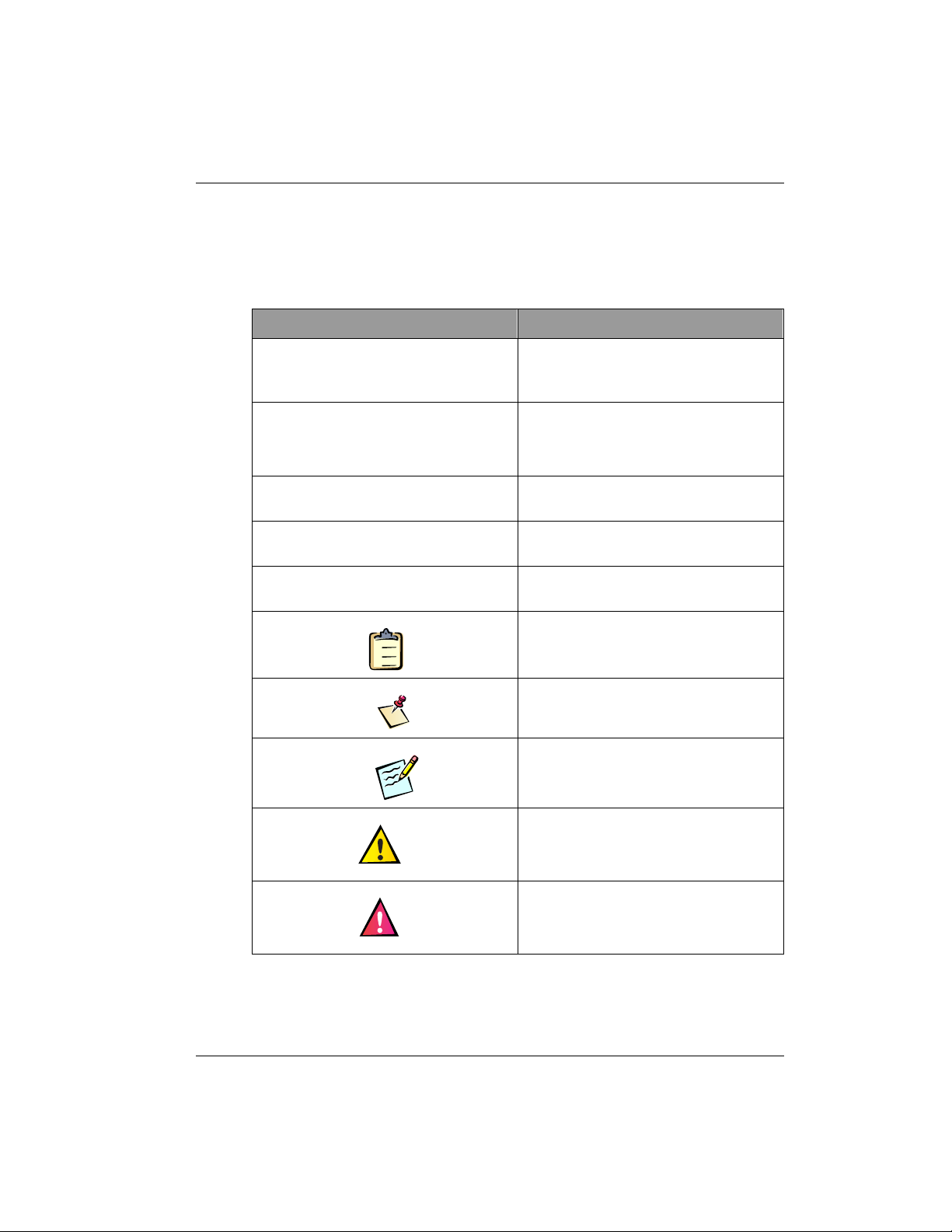
Notational Conventions
The following table shows the notational conventions that
convey specific types of information in this manual.
Convention Description
About This Manual
Commands, parameters,
values, filenames,
directory locations
Items shown in courier typeface
indicate commands, parameters,
filenames, and directory locations.
<Non-literal elements> Items shown within angle brackets
and
<courier> indicate non-literal
elements for which you type a
substitute.
Menu items and buttons Menu items, commands, and buttons
Dialog box and window titles Dialog box and window titles appear in
Book titles and section references Book titles and section references
Steps
1
2
3
Note
Tip
Tip
appear in bold sans serif.
bold sans serif.
appear in italics.
This symbol identifies “how-to”
procedure. Follow these steps to
accomplish a specific task.
This symbol identifies related
information that deserves emphasis.
This symbol identifies a shortcut or
information that you might find
handy.
Caution
Warning
80-99208-1 Rev. D xix
This symbol identifies a potentially
hazardous situation which, if not
avoided, could damage equipment or
property.
This symbol and bold text identify
potential danger, which, if not
avoided, could cause serious injury or
death.
Page 19

Integrator’s Reference Manual
Abbreviations and Acronyms
AC Alternating Current
API Application Programming Interface
AT Attention
CCA Circuit Card Assemblies
CDMA Code Division Multiple Access
CDR Call Detail Record
CD-ROM Compact Disc Read-Only Memory
CE Community European
CFR Code of Federal Rules
CP Control Port
CTS Clear To Send
DC Direct Current
DCD Data Carrier Detect
DCE Data Communications Equipment
DM Diagnostic Monitor
DN Directory Number
DNI Do Not Install
DNS Domain Name Server
DP Data Port
DRA Dielectric Resonator Antenna (see ODU)
DSR Data Set Ready
DTE Data Terminating Equipment
DTR Data Terminal Ready
EIRP Equivalent Isotropic Radiated Power
ESD Electrostatic Discharge
ESN Electronic Serial Number
FAX Facsimile
FCC Federal Communications Commission
xx 80-99208-1 Rev. D
Page 20

About This Manual
FDX Full-Duplex
GAI Globalstar Air Interface
GEO geostationary-Earth-orbit
GLP Globalstar Limited Partnership
GMT Greenwich Mean Time
GND Ground or Signal Common
GPS Global Positioning System
GW Gateway
IMSI International Mobile Subscriber Identity
IP Internet Protocol
ISP Internet Service Provider
IWF Interworking Function (Gateway)
LCD Liquid Crystal Display
LEO low-Earth-orbit
LNA Low Noise Amplifier
MCC Mobile Country Code
MCX Miniature Coaxial Connector
MEO medium-Earth-orbit
MIK Modem Integrator’s Kit
MNC Mobile Network Code
MPE Maximum Permissible Exposure
MSIN Mobile Station Identification Number
MSS Mobile Satellite System
NAM Number Assignment Module
ODU Outdoor Unit (see DRA)
OEM Original Equipment Manufacturer
OSPL Overall Sound Pressure Level
PC Personal Computer
PDF Portable Document File
PDT Pacific Daylight Time
80-99208-1 Rev. D xxi
Page 21

Integrator’s Reference Manual
PLS Position Location Service
POS Point of Sale; or Position
PPP Point-to-Point Protocol
PST Pacific Standard Time
PSTN Public Switched Telephone Network
PT Pacific Time
QA Quality Assurance
RF Radio Frequency
RFR Ready For Receive
RI Ring Indicator
RLSD Received Line Signal Detector
RMA Return Material Authorization
RSSI Received Signal Strength Indicator
RTS Ready To Send
RTU Remote Termination Unit
R
X Receive
R
XD Receive Data
SCADA Supervisory Control and Data Acquisition
SLIP Serial Line Internet Protocol
SMA Subminiature type “A” Connector
SMS Short Messaging Service
SMT Surface Mount Technology
SP Service Provider
SPC Service Programming Code
TCP Transmission Control Protocol
TCXO Temperature Compensated Crystal
Oscillator
TSS Technical Support Specialist
TTL Transistor Transistor Logic
T
X Transmit
xxii 80-99208 -1 Rev. D
Page 22

TXDTransmit Data
UCT Universal Coordinated Time
URL Uniform Resource Locator
UT User Terminal
UTC Universal Time Coordinated
UTPST User Terminal Program Support Tool
VPN Virtual Private Network
VSWR Voltage Standing Wave Ratio
Related Document ation
Globalstar UT Program Support Tool User’s Guide,
80-98225-1.
Globalstar User Terminal Service Programming Guide,
80-98482-1.
Globalstar UTPST Script API Reference Manual, 80-99114-1.
QUALCOMM Globalstar Data User Guide, 80-99126-1.
About This Manual
QUALCOMM Globalstar Modem Operation Monitor User’s
Guide, 80-99399-1.
80-99208-1 Rev. D xxi ii
Page 23

Integrator’s Reference Manual
Warning
Caution
Caution
Cautions and Warnin gs
Before working with the modem hardware or power connections,
remove rings, watc hes, and other metallic objects that could cause
electrical shock or burns.
Use proper elect rostatic dis charge (ESD) equipment and procedures to
avoid damage to the modem.
Any changes or mod ification s to this equipm ent not expr essly appr oved
in this doc ument coul d v oid your warra nty and y our authori ty t o operat e
this equipment .
xxiv 80-99208-1 Rev. D
Page 24

1 GETTING STARTED
Welcome to the Integrator’s Reference Manual for the
QUALCOMM Globalstar GSP-1620 Satellite Data Modem.
The GSP-1620 modem offers data communication solutions,
particularly for Remote Monitoring and Supervisory Control
and Data Acquisition (SCADA) applications in locations such
as power substations, telecommunication concentration
nodes, oil and gas wells, pipes, and offshore facilities.
Whether you are an application developer, system integrator,
or Original Equipment Manufacturer (OEM), this
Integrator’s Reference Manual contains information you need.
If you want to: Go to:
■ Bench-set up, connect, and power-up the
GSP-1620 modem in the Modem
Integrator’s Kit, and get HyperTerminal
to talk to the modem
■ Service-program modems to work with
your Service Provider (SP) and within the
Globalstar system
■ Set up your computer for packet data and
make a simple packet data call
■ Develop market-specific application
software to work with the GSP-1620
modem (using packet data or
asynchronous data)
■ Understand modem AT commands
■ Mount GSP-1620 modems and antennas
for market-specific OEM products
(including all hardware and
environmental specifications)
■ Troubleshoot modem problems
Chapter 2
Chapter 3
Chapter 4
Chapter 5
Chapter 6
Chapter 7
Chapter 8
80-99208-1 Rev. D 1-1
Page 25

Integrator’s Reference Manual
Tip
Note
GSP-1620 Modem Overview
The QUALCOMM Globalstar GSP-1620 Satellite Data
Modem delivers reliable digital data communications
wherever Globalstar data service is available, using
QUALCOMM’s patented CDMA technology and the
Globalstar Communications System’s constellation of 48
low-Earth-orbit (LEO) satellites.
The GSP-1620 modem handles two kinds of data connections:
• Packet — over the Internet or other TCP/IP
packet-switched network
• Asynchronous — routed through the Public Switched
Telephone Network (PSTN) to a destination modem
QUALCOMM Globalst ar p acket d ata ser vi ce has a lowe r overh ead a nd
faster connection time than asynchronous data does. If a SCADA
application d oes n ot specif ical ly need asynchr onous data, it s hould us e
packet data instead.
As an OEM, you directly integrate the GSP-1620 modem into
a market-specific product, to resell to a business/industrial
customer.
For additio nal information about t he Globalstar system, see Globalstar
Background, page A-1. For information about buying bul k modems from
QUALCOMM, contact QUALCOMM Glob alstar Customer Service as
described in Appendix D.
1-2 80-99208-1 Rev. D
Page 26

Typical Modem SCADA Applications
In remote settings or difficult-to-access sites, acquiring and
responding to process control and alarm data can be
challenging and costly. For both system integrators and
OEMs, the QUALCOMM Globalstar GSP-1620 Satellite Data
Modem provides real-time, low cost, bi-directional data
communication solution applications in remote locations for
fixed or mobile use.
The GSP-1620 modem lets you retrieve data automatically
from remote sites. Unmanned sensors connected to the
GSP-1620 modem can monitor remote operations and initiate
alert notifications.
Table 1-1 lists some typical Remote Monitoring and
Supervisory Control and Data Acquisition (SCADA)
applications.
T able 1-1. T ypical GSP-1620 Modem Applications
Getting Started
Electric Utility Industry Remote Security Systems
Oil and Gas Wells, Tanks,
Pipelines, Offshore Platforms
Water Treatment Plants Retail Point of Sale (POS)
Remote Inventory
Management
Electronic Billboards Agriculture
Highway Traffic Monitoring Aircraft Weather/Messaging
Monitoring
Energy Management
Transactions
Remote Banking
for Commercial and General
Aviation
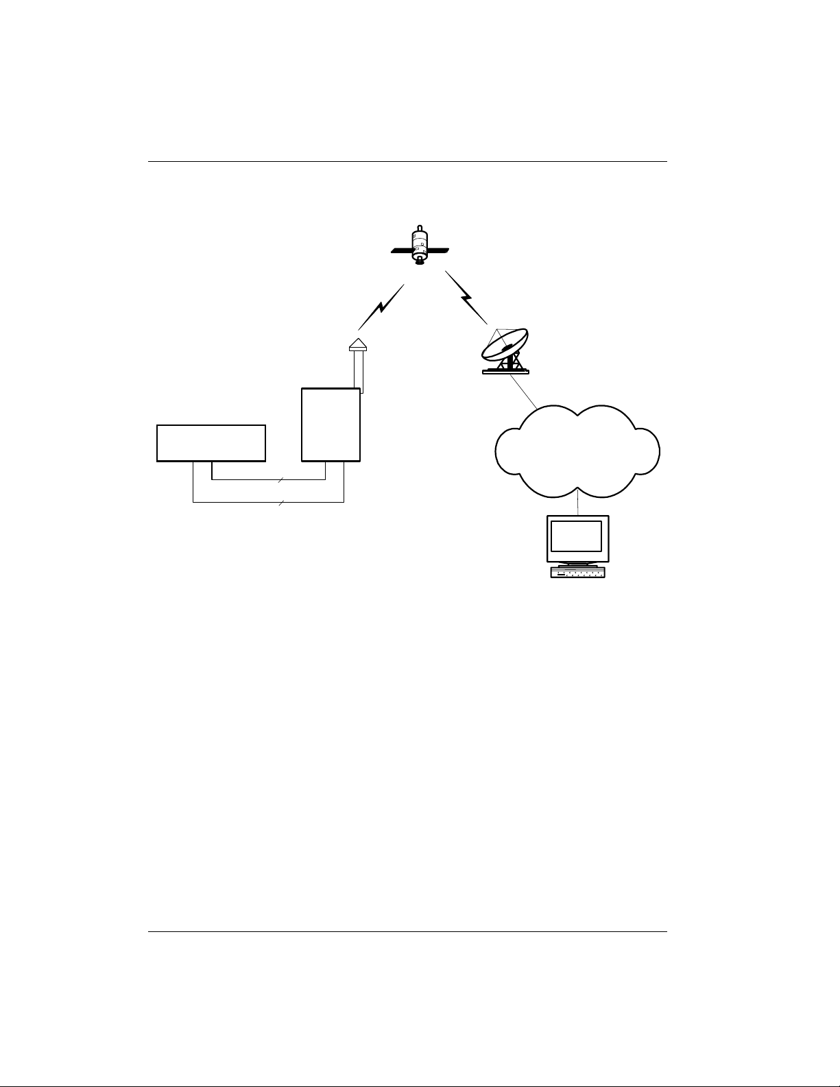
Figure 1-1 depicts a typical use of the GSP-1620 modem for a
SCADA application using packet data.
80-99208-1 Rev. D 1-3
Page 27
Integrator’s Reference Manual
Figure 1-1. Typi cal Modem SCADA Appl ication Usi ng Pack et Data
Satellite
Remote
DTE
SCADA Terminal
Outdoor Antenna
Rx
Tx
Globalstar
Gateway
DCE
GSP-1620
Modem
Internet
Data Port
Control Port
Host
Server
For packet data connections, the GSP-1620 modem
essentially functions as a “node” on the Internet and, with its
fixed or dynamically assigned IP address, can be addressed in
real time as often as necessary to maintain application
control over the remote devices.
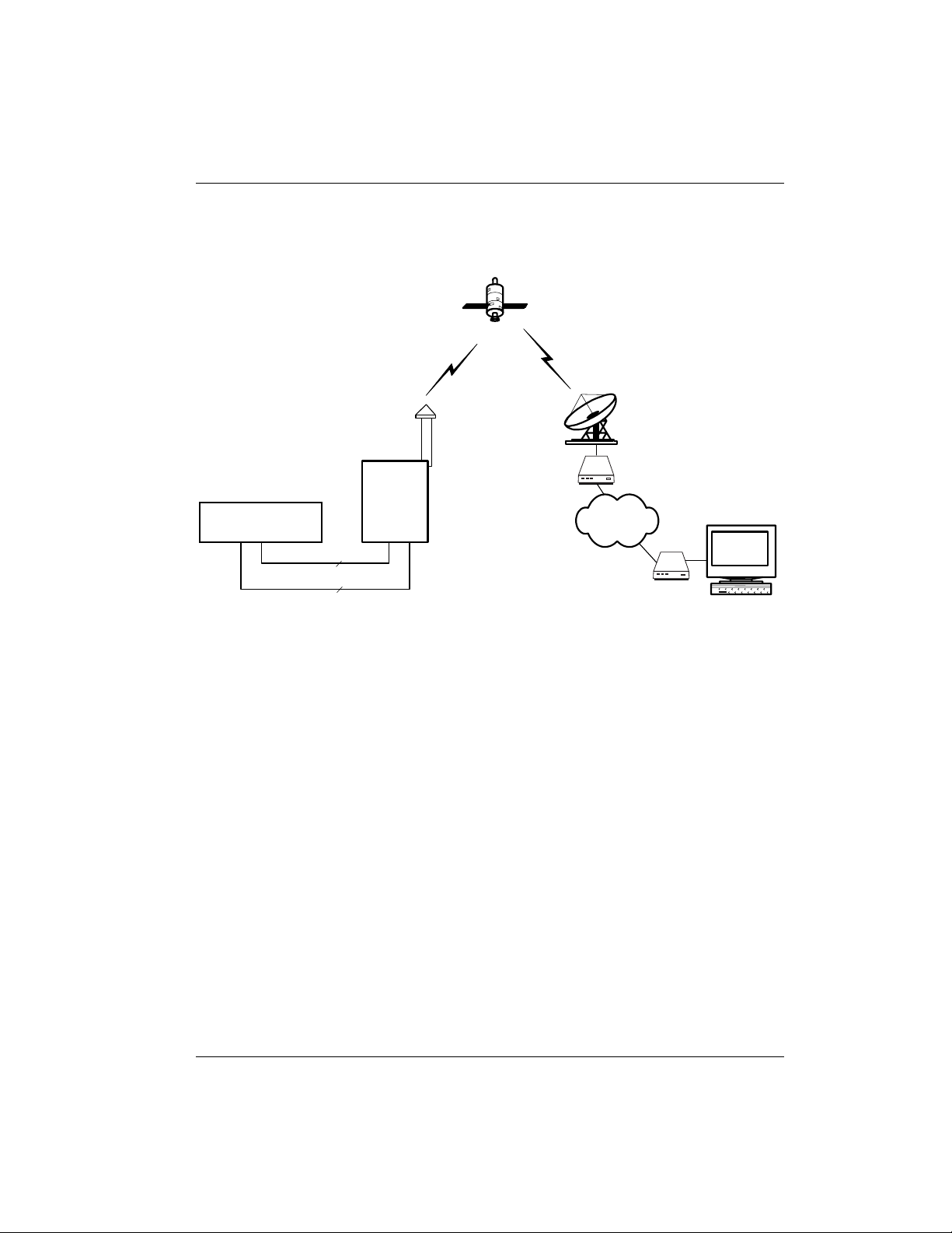
Figure 1-2 depicts a typical use of the GSP-1620 modem for a
SCADA application using asynchronous data.
1-4 80-99208-1 Rev. D
Page 28
Getting Started
Figure 1-2. Typical Modem SCADA Application Using
Asynchronous Data
Satellite
Remote
DTE
SCADA Terminal
Outdoor Antenna
Data Port
Control Port
Globalstar
Tx
Rx
Gateway
DCE
Gateway IWF Modem
GSP-1620
Modem
PSTN
Host Modem
Host
Server
For asynchronous data connections, the GSP-1620 modem
can dial or be dialed by a host modem, connecting through the
Globalstar Satellite Communications System and the PSTN.
You can think of the GSP-1620 modem in Figure 1-1 and
Figure 1-2 as a 9600 bps full duplex satellite modem. The
modem uses typical Hayes AT commands (see Chapter 6, AT
Command Reference). Standard RS-232 interfaces facilitate
ease of use and OEM application integration.
For either packet or asynchronous connections, OEMs
provide the host application (server), which uses the
GSP-1620 modem to communicate with a custom SCADA
application on data terminating equipment (DTE) at a remote
site. The host application manages the field processing of
data and reports process exceptions, performance reports,
alarm conditions—in short, any data needed from the
remote site.
80-99208-1 Rev. D 1-5
Page 29
Integrator’s Reference Manual
For example, in the electric utility industry, a SCADA
application using the GSP-1620 modem could remotely turn
on a pump, close a switch, open a gate, request a new meter
reading, monitor line voltage, or report on power outages.
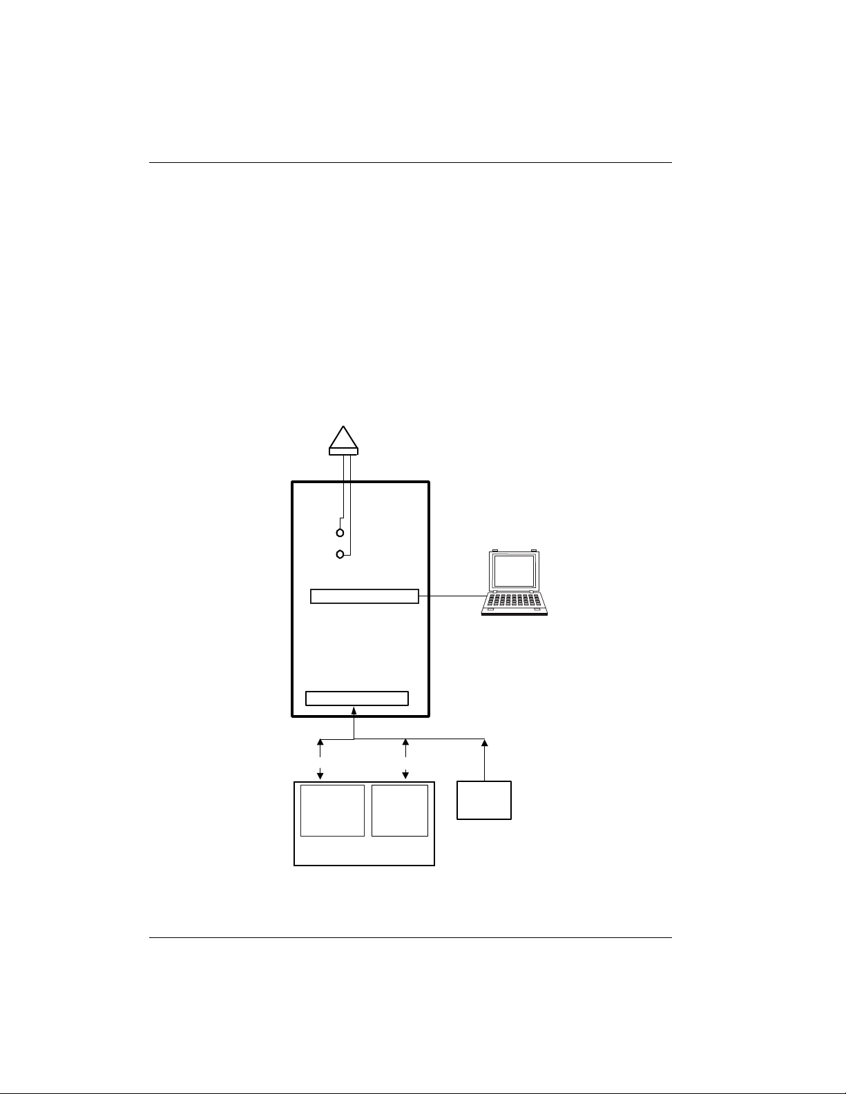
Conceptual Overview
Figure 1-3 depicts a conceptual overview of the QUALCOMM
Globalstar GSP-1620 Satellite Data Modem, including its
ports and antenna.
Figure 1-3. Conceptual Diagram of GSP-1620 Modem
Outdoor
Antenna
Rx
Tx
Diagnostic Port
GSP-1620
Modem
Interface Port
Serial Control Port
Modem AT
commands
SCADA Application Terminal
Serial Data Port
Data
or AT
commands
UT Program Support Tool
(UTPST)
for service programming
DC Power
5.6V-16V
1-6 80-99208-1 Rev. D
Page 30

Getting Started
The GSP-1620 modem is a bare board “sandwich” stack of
Circuit Card Assemblies (CCA) containing two boards:
• Globalstar RF board — includes the LNA, RF power amp,
upconverters and downconverters, TCXO, synthesizers,
and the remaining power electronics.
• Globalstar Digital board — includes the processor, the
modem, and some of the power management electronics.
QUALCOMM offers the GSP-1620 modem without a
mechanical enclosure, anticipating that OEMs will integrate
and package the modem with the end-user’s application.
The GSP-1620 modem operates in the “Globalstar (or
satellite) data mode only,” as opposed to the GSP-1600
Tri-Mode Phone, which has additional terrestrial cellular
(analog and digital) and voice capabilities. The GSP-1620
modem is powered by an external power source provided by
the user.
A weatherproof Dielectric Resonator Antenna (DRA),
sometimes referred to as an Outdoor Unit (ODU), comes with
each modem. OEMs provide antenna cables (SMA to MCX
connectors), to meet customer antenna-cable length needs.
A single DB-25 (male) connector is used for the user interface
port. The DB-25 carries DC power, as well as the Data and
Control RS-232 signals, between the SCADA application
(DTE) and the modem (DCE).
A Diagnostic port on the modem allows network provisioning
(service programming) and software upgrades.
What’s in the Modem Integrator’s Kit?
Your GSP-1620 Modem Integrator’s Kit (MIK) is designed to
help you rapidly develop user applications for GSP-1620
modems.
Table 1-2 shows the items contained in your GSP-1620
Modem Integrator’s Kit (QUALCOMM part number: MCN
65-82317-1).
80-99208-1 Rev. D 1-7
Page 31

Integrator’s Reference Manual
T able 1-2. Checklist of Modem Integrat or’s Kit Components
Kit Component
QUALCOMM Globalstar GSP-1620 Satellite Data Modem
Dielectric Resonating Antenna (DRA)
Pair of antenna cables with connectors (for quick bench
setup of the kit modem)
Custom DB-25 cable bridle, which splits out the DE-9 Data
Port connector, the DE-9 Control Port connector, and the
DC power leads (positive, negative, and reset)
Diagnostic port cable, for service-programming the modem
or to use as alternate power source via its AC adapter
GSP-1620 modem CD-ROM containing the following:
■ Software code samples for modem applications
■ A “soft copy” (PDF file) of this Integrator’s Reference
Manual
■ “CDMA by QUALCOMM” logo in an Encapsulated
PostScript (EPS) file
■ A “soft copy” (PDF file) of the QUALCOMM Globalstar
Data User Guide, 80-99126-1EN, as a guide for the
setup of a Windows modem driver and Windows
Dial-Up Networking.
Globalstar UT Program Support Tool (UTPST), including:
■ CD-ROM containing the UTPST software and a “soft
copy” (PDF file) of the Globalstar UTPST Script API
Reference Manual, 80-99114-1
■ Globalstar UT Program Support Tool User’s Guide,
80-98225-1
■ Globalstar User Terminal Service Programming
Guide, 80-98482-1
1-8 80-99208-1 Rev. D
Page 32

What You May Need in Addition to the Kit
The Modem Integrator’s Kit should be sufficient for setting
up one modem on a bench for development and testing.
For GSP-1620 modem development purposes (bench setup
and developing modem applications), it is recommended that
you have a Windows PC, because the Modem Integrator’s Kit
CD-ROM contains some Windows code samples.
If necessary, you can power the modem via the AC adapter on
the Diagnostic cable, but you may prefer to use your own DC
power supply. Mounting a bench modem and antenna is
optional, but would require M3 and M4 screws, respectively,
and a screwdriver.
OEMs who are packaging modems into end-user products will
need to supply mounting enclosures and customized cables.
For details, see Integrating GSP-1620 Modems into OEM
Products on page 7-1.
Configuration and setup of computer systems to use the
GSP-1620 modem with Point-to-Point Protocol (PPP) is
beyond the scope of this document. However, the
configuration procedures for the QUALCOMM Globalstar
GSP-1600 Tri-Mode Phone are included as a reference in the
QUALCOMM Globalstar Data User Guide, 80-99126-1
(located on the kit’s CD-ROM). For example, using the
procedures in that document, you can set up a Windows
modem driver and Windows Dial-Up Networking. With the
proper DNS addresses from your Service Provider (SP) or
Internet Service Provider (ISP), you can access the Internet
using your GSP-1620 modem via the Globalstar satellite
system.
Getting Started
80-99208-1 Rev. D 1-9
Page 33

Integrator’s Reference Manual
1-10 80-99208-1 Rev. D
Page 34

2 QUICK BENCH SET-UP
Note
Caution
Your GSP-1620 Modem Integrator’s Kit contains a
QUALCOMM Globalstar GSP-1620 Satellite Data Modem.
This chapter tells how to quickly set up the GSP-1620 modem
on a test bench so that you can interact with it, including the
following topics:
• Connecting hardware components as appropriate for a
bench setup
• Providing power to the modem
• Setting up HyperTerminal to talk to the modem and
query its status, using modem AT commands
Keep in mind that the quick bench setup shown in this
chapter differs from the setup you might use for developing
applications, integrating modems permanently into OEM
products, or for field installation.
For example, in the quick bench setup, you communicate with
the modem by typing AT commands into HyperTerminal,
whereas a SCADA application will communicate with the
modem using AT commands embedded within its code.
Also, in the quick bench setup, you can use the cables
provided in the kit to connect to the modem ports and
antenna, whereas for a SCADA field installation, OEMs will
make custom cables.
Examples in this chap ter assume you are connec ting a Win dows PC to
the modem.
For your safety and to avoi d potential damage to the equipment ,
observe the Cauti ons and W arnings on page xxiv.
80-99208-1 Rev. D 2-1
Page 35

Integrator’s Reference Manual
Tip
Caution
Connecting Hardware Components
The setup process for the GSP-1620 modem includes:
• A quick tour of the modem
• Connecting the modem cables
❑ Connecting the Interface cable (Data port, Control
port, power) to the modem and to your PC
❑ Connecting the antenna cables (Tx, Rx) to the modem
❑ Connecting the Diagnostic cable (if you want to power
the modem from its AC adapter, service-program the
modem, or monitor some modem functions)
• Connecting and mounting the antenna
• Mounting the modem (optional)
• Grounding the system
• Providing power to the modem
• Setting up HyperTerminal to talk to the modem and
testing your connection
A Windows PC is recommended for modem bench setup and
application development. Modem s m ust be service pr ogrammed using
the Globals tar UT Program Suppor t Tool, which is a Windows software
application.
A Quick Tour of the Modem
For quick bench set-up, first remove the GSP-1620 modem
from the GSP-1620 Modem Integrator’s Kit.
When handling the modem , observe precautions necessary to avoid
damage by electrost atic discharge (ESD).
Compare the GSP-1620 modem to Figure 2-1. This
illustration shows the connectors and components you will
use in the following sections.
2-2 80-99208-1 Rev. D
Page 36

Quick Bench Set-Up
Figure 2-1. Simplified Top View of GSP-1620 Modem
Mounting hole
Mounting hole
Mounting hole
Receive (Rx) ant en na lead
conn ec ts he re ( J7 )
Transmit (Tx) antenna lead
conn ec ts he re ( J3 )
Diagnostic Port
(Diagnostic cable
conn ec ts he re for
UTPST, AC power
adapter, or Modem
Operation Monitor)
Mounting hole
Mounting hole
Inter face Port:
combines Data Port,
Control Port, and DC Power input
(Modem Interface Cable from kit
connects here, or OEMs
make their own custom cables)
Mounting hole
:
80-99208-1 Rev. D 2-3
Page 37

Integrator’s Reference Manual
Connecting the Modem Cables
For the GSP-1620 modem to work, you must connect several
cables:
• Modem interface cable — connects the Data port to a PC,
connects the Control port to a PC (optional), and connects
power leads to a DC power supply.
• Antenna cables — connect the transmit (Tx, J3) and
receive (Rx, J7) leads to the Tx and Rx connectors on the
Dielectric Resonator Antenna.
• Diagnostic cable — connects the Diagnostic port to a PC
running the Globalstar UT Program Support Tool
(UTPST) for modem service programming, or the
QUALCOMM Globalstar Modem Operation Monitor; can
also be used as an optional, alternate power supply via its
AC adapter.
Connecting the Modem Interface Cable
Your Modem Integrator’s Kit includes a custom DB-25
modem interface cable bridle, which connects to the Interface
port on the modem. The cable bridle splits out the DE-9 Data
Port and DE-9 Control Port, and the DC power connectors
(DC POWER, SIG GND, and RESET), as shown in Figure 2-2.
Figure 2-2. Modem Interface Cable Bridle
Modem Interface Cable
Modem connector
To modem
Power connectors:
"SIG GND" (black) "RESET"
"DC POWER" (red)
To DC power supply
(user-provided)
2-4 80-99208-1 Rev. D
(yellow)
Open
(ground to reset)
"P2-DATA PORT"
PC serial connector
To PC
"P3-CONTROL"
PC serial connector
To PC
Page 38

Quick Bench Set-Up
Steps
Steps
Note
TO CONNECT THE INTERFACE CABLE TO THE MODEM
1
2
3
■ Connect the DB-25 modem connector on the interface
cable (Figure 2-2) to the interface port on the modem
(Figure 2-1).
Do not connect power yet.
TO CONNECT THE INTERFACE CABLES TO YOUR PC
1
2
3
1. On the interface cable (Figure 2-2), connect the Data port
connector (labeled “P2-DATA PORT”) to COM 1 or
another available serial COM port on your PC.
The Data port transmits packet (PPP) or asynchronous
data. You can also use it to send AT commands to the
modem. You will see an example of how this works in
Chapter 4.
2. On the interface cable (Figure 2-2), connect the Control
port connector (labeled “P3-CONTROL”) to COM 2 or
another available serial COM port on your PC (or a
different PC, if desired).
You can use the Control port to send AT commands to the
modem, without interrupting data flow on the Data port.
You will see an example of how this works in Chapter 4.
The Control port can also receive SMS messages; for
information, see Short Messaging Service (SMS) on page
5-17.
If you need to extend the interface cables to r each your PC(s), you can
use straight RS-232 9-pin serial cables (with no crossovers). For
maximum RS-232 extensi on cable lengths, see the TIA/EIA-232-E
specification.
80-99208-1 Rev. D 2-5
Page 39

Integrator’s Reference Manual
Caution
Steps
Connecting Antenna Cables
The Modem Integrator’s Kit contains two antenna cables (3
feet long) with snap-in connectors, for connecting the modem
to the Dielectric Resonator Antenna (DRA). The antenna
must be located outdoors.
Due to loss constraints on antenna length (see Calculating
Antenna Cable Length on page 7-27), if you need to extend the
kit cables to reach your antenna, it is more practical to locate
the modem closer to the antenna and extend the modem’s
serial cables instead. For a tip on how to do this, see
Connecting and Mounting the Antenna on page 2-9.
OEMs must supply custom antenna cables for their modem
applications.
Either antenna cable in the developer’s kit can be used for tra nsm it or
receive; however, you must make sure not to cross them. In other
words, be careful to connect the Tx connector on the antenna to the Tx
connector (J3) on the modem, and the Rx connect or on the antenna t o
the Rx connector (J 7) on th e mode m. Crossing the Tx and Rx cables
can damage the modem.
TO CONNECT THE ANTENNA CABLES TO THE MODEM
1
2
3
1. Select one antenna cable to be the transmit cable (it does
not matter which one).
2. Label both ends of that cable with “Tx.” For example, you
could write “Tx” on a piece of tape wrapped around each
end of the cable.
3. Plug either end of the cable marked “Tx” into the transmit
(Tx) connector (J3) on the modem, as shown in Figure 2-1.
4. Plug either end of the unmarked cable into the receive
(Rx) connector (J7) on the modem, as shown in Figure 2-1.
2-6 80-99208-1 Rev. D
Page 40

Quick Bench Set-Up
Note
Tip
Connecting the Diagnostic Cable
The Diagnostic cable lets you:
• Service-program GSP-1620 modems, using the
Globalstar User Terminal Program Support Tool
(UTPST). For more information about the UTPST, see
UTPST Overview on page 3-2.
• Monitor or verify some modem functions, using the
QUALCOMM Globalstar Modem Operation Monitor.
For more information, see the QUALCOMM Globalstar
Modem Operation Monitor User’s Guide, 80-99399-1.
The cable includes an optional AC adapter. If a DC power
supply is not available on your bench, you can power the
modem with the AC adapter on the Diagnostic cable.
The Diagnostic cable also includes a switch box that controls
whether the cable’s DTR (Data Terminal Ready) signal is
asserted (“POS 1 DTR to GND”) or de-asserted (“POS 2 DTR
Open” or “POS 3 Not Used”). When DTR is asserted, the
modem powers up immediately if power is provided. Before
powering down the modem with this cable attached, you must
set this switch to “POS 2” or “POS 3.”
On the switch box, “POS 2 DTR Open” and “POS 3 Not Used” are
functionally equivalent. Some cables are equipped with a two-position
switch box and do not have “ POS 3.” The swi tch positions for these
cables are “POS 1 DTR to GND” (DTR asserted) and “POS 2 DTR
Open” (DTR de-assert ed).
When the Diagnostic cable is connected but you are not using the
UTPST to service-progr am the modem, leave the Diagnostic cable
switch in the “POS 2 DTR Open” (de-as serted) position.
80-99208-1 Rev. D 2-7
Page 41

Integrator’s Reference Manual
Figure 2-3. Modem Diagnostic Cable
AC Wall
adapter
PC Connector
"P1 - PC"
Lock ring
Power
connector
Locking
threads
DTR OPEN
POS 1
DTR to GRD
DTR Switch box
T able 2-1. DTR Switch Positions
POS 2
Modem connector
"P2 - module"
POS 3
NOT USED
005AA_01
Position Switch Label Effect
POS 1 DTR to GND DTR is asserted.
POS 2 DTR Open DTR is de-asserted.
POS 3 Not Used DTR is de-asserted
(equivalent to POS 2).
Note: Some cables are equipped with a
two-position switch box and do not
have “POS 3.” The switch positions for
these cables are “POS 1 DTR to GND”
(DTR asserted) and “POS 2 DTR
Open” (DTR de-asserted).
2-8 80-99208-1 Rev. D
Page 42

Steps
TO CONNECT THE DIAGNOSTIC PORT CABLE
Caution
Tip
1
2
3
1. Connect the DE-9 modem connector (“P2-Module”) on the
Diagnostic cable (Figure 2-3) to the 9-pin Diagnostic port
on the modem (Figure 2-1).
2. Connect the DE-9 PC connector (“P1-PC”) on the
Diagnostic cable to a COM port on your computer.
3. Locate the switch on the cable, and set it to “POS 1 DTR
to GND.”
Do not plug in the AC wall adapter yet. For information
about powering the modem, see Providing Power to the
Modem on page 2-12.
Connecting and Mounting the Antenna
The GSP-1620 modem uses a Dielectric Resonator Antenna
(DRA) with a passive transmit and an active receive section.
The transmit (Tx) and receive (Rx) connectors are labeled on
the base of the antenna.
Since the antenna communicates with Globalstar satellites, it
must be positioned outdoors where it has a clear view of the
sky, unimpeded by tall obstacles such as buildings and trees.
Quick Bench Set-Up
Antenna cable leng th i s li m it ed, due to insertion loss and potential
emission probl em s. For details, see Antenna Cable Specifications on
page 7-25 and Calculating Antenna Cable Length on page 7-27.
For a quick setup, you may want to mount the antenna on top of a
water-tight b ox on y our roof . Mount the mo dem insi de the box , then r un
extension cabl es (straight RS-232 9-pin seri al cables with no
crossovers) for the power and serial connectors to your indoor bench.
(For maximum RS-232 extensi on cable lengths, see th e TIA/EIA-232-E
specifica tion. ) A box s et up let s you use the antenna cabl es fr om th e kit,
without worrying about antenna cable length.
80-99208-1 Rev. D 2-9
Page 43

Integrator’s Reference Manual
Steps
Caution
Figure 2-4. Antenna Base Showing Connectors
TO MOUNT THE ANTENNA
1
2
3
1. Locate the antenna outdoors where it has a clear view of
the sky. Make sure the antenna is close enough to the
modem that you can use the antenna cables provided in
the Modem Integrator’s Kit.
O-Ring groove
RX Antenna connector
(labeled on antenna base)
TX Antenna connector
(labeled on antenna base)
The antenna must have a clear view of the sky to get a
strong signal.
2. Plug the antenna cable that you labeled “Tx” into the
transmit connector (also labeled Tx) on the antenna
(Figure 2-4). Make sure the other end of the cable is
connected to the J3 connector on the modem.
You must be careful to connect the Tx connector on the antenna to the
Tx connector on the modem, and the Rx connector on the antenna to
the Rx connector on the mode m. Crossing the Tx and Rx cables can
damage the modem.
2-10 80-99208-1 Rev. D
Page 44

3. Plug the other antenna cable into the receive (Rx)
Note
Caution
4. Secure the antenna to a flat surface using six M4 screws
For complete details about sealing the antenna to a flat mounting
surface, or for information about mounti ng antennas on poles, see
Mounting Antennas at the Field Site on page 7-27.
Mounting the Modem
For quick bench set-up, you probably do not need to mount
the modem to a surface or in an enclosure, as it would be
mounted in an OEM product for use in the field.
Quick Bench Set-Up
connector on the antenna.
through the six mounting holes. To prevent moisture and
dirt from getting underneath the antenna and onto the
connectors, you can use an O-ring (2.050 inches in
diameter by 0.103 inch wide, silicone or ethylenepropylene) if the mounting surface is smooth, or adhesive
caulking if the surface is rough.
If you do wish to fasten the modem to a rigid structure, you
will need six M3 screws (see mounting holes in Figure 2-1).
For details, see Modem Mounting Guidelines on page 7-19.
For details on acceptable environmental conditions for the
modem, see Environmental Specifications on page 7-30.
For a tip on how to mount the modem and antenna using a
box, see Connecting and Mounting the Antenna on page 2-9.
Grounding the System
You have several options for grounding the modem; see
Grounding on page 7-18.
The RF connector ground i s the same as the signal and power ground.
Incorrect ly wiring these grounds could cause ground loops in the final
installation.
80-99208-1 Rev. D 2-11
Page 45

Integrator’s Reference Manual
Tip
Caution
Note
Providing Power to th e Modem
The GSP-1620 modem requires input DC power of 5.6 V to
16 V, 1 Amp (maximum), with a maximum of 50 mV
peak-peak ripple and noise.
Using the contents of the Modem Integrator’s Kit, you can
power your bench modem in two ways:
• Use the AC adapter on the Diagnostic cable
• Use an optional DC power supply connected to the
Interface cable bridle — this allows you to monitor exact
power levels
The use of a fuse is strongly recommended in the DC power
supply. A fuse with a minimum melting I
2
t rating of 0.02 A
seconds will be sufficient. For complete details about DC
power requirements and power supply impedances, see DC
Power on page 7-15.
For a quick bench set up or service program ming, consider just using the
provided AC adapter to power the modem.
You CANNOT have both a DC power supply and the AC adapter
connected to the modem at the same ti me. Thi s may c ause the modem
to fail to power up and may damage the modem.
The following power-on procedure is suitable for a bench setup.
However, if you are developing modem applications, follow th e
power-on process explained in Power-On on page 7-17.
2
2-12 80-99208-1 Rev. D
Page 46

Quick Bench Set-Up
Steps
TO POWER THE MODEM USING THE KIT’S AC ADAPTER
1
2
3
1. On the Modem Interface cable bridle (shown in Figure
2-2), locate the DC POWER (red) and SIG GND (black)
connectors. Then electrically isolate each connector by
capping or taping it.
Since you will be using the AC adapter instead of a DC
power supply, it is important to isolate the DC power
connectors to prevent shock.
2. On the Modem Interface cable bridle (shown in Figure
2-2), locate the RESET lead (yellow). Electrically isolate
the RESET lead by capping or taping it.
The RESET lead is designed to reset the GSP-1620
modem whenever it is grounded for five seconds.
Electrically isolating the lead prevents it from grounding
and inadvertently resetting the modem.
3. Locate the power connector in the middle of the
Diagnostic cable (as shown in Figure 2-3), then plug the
the AC wall adapter cable into the power connector.
4. Tighten the lock ring on the adapter cable onto the
locking threads of the power connector, so the adapter
plug remains firmly seated in the power connector.
The lock ring prevents the adapter cable and Diagnostic
cable from inadvertently disconnecting and interrupting
power to the modem.
5. Make sure the switch on the Diagnostic cable is set to
“POS 1 DTR to GND.”
When this switch is set to “POS 1 DTR to GND,” DTR is
asserted on the Diagnostic cable and the modem will
power up immediately when power is applied.
6. Plug the AC wall adapter (as shown in Figure 2-3) into an
AC power wall outlet.
You are now ready to use the modem.
80-99208-1 Rev. D 2-13
Page 47

Integrator’s Reference Manual
Caution
Steps
T o power of f the GSP-1620 mode m, s et the DTR s witch to “POS 2 DTR
Open,” wait at least 10 se conds, a nd then dis connect power. Setting the
DTR switch to “POS 2” allows the modem to gracef ully shut down. If the
modem is powered off without allowing it to go through its shutdown
sequence, some se rvice programming value s may be lost .
TO POWER THE MODEM USING AN OPTIONAL DC POWER
1
2
3
SUPPLY
1. Obtain an optional DC power supply, making sure that it
meets the specifications described at the beginning of this
section.
2. On the Modem Interface cable bridle (shown in Figure
2-2), locate the RESET lead (yellow). Electrically isolate
the RESET lead by capping or taping it.
The RESET lead is designed to reset the GSP-1620
modem whenever it is grounded for five seconds.
Electrically isolating the lead prevents it from grounding
and inadvertently resetting the modem.
3. Plug the DC POWER (red) and SIG GND (black) leads
from the Modem Interface cable bridle into your DC
power source.
4. Turn on the power supply.
You are now ready to use the modem.
2-14 80-99208-1 Rev. D
Page 48

Quick Bench Set-Up
Note
Steps
Setting Up HyperTerminal to Talk to the Modem
To talk to the modem you will need HyperTerminal or a
similar program on your computer. If you are using an
operating system other than Windows, you can use any
application that can talk to a serial port.
For bench setup, you pr obably want to run HyperTerminal on the
computer connected to the Control port of the modem. For testing
purposes, you can run two different Hyper Terminal sessions, one
connected to the Cont rol port and one connected to the Dat a port .
TO SET UP HYPERTERMINAL AND CONNECT TO THE MODEM
1
2
3
1. Set up HyperTerminal with the correct port and speed
information for the appropriate port (or both ports, if you
have two HyperTerminal sessions).
The following are the recommended HyperTerminal
settings for the Control and Data ports:
Name
Connect using
Bits per second
Data bi ts
Parity
Stop bits
Flow control
80-99208-1 Rev. D 2-15
Control port: GSP1620_Control
Data port: GSP1620_Data
Computer COM port connected to
modem Control port or Data port
Control port: 9600 (fixed)
Data port: 38400 (default, but can
vary from 300 to 115200)
8
None
1
Control port: None
Data port: Hardware (default and
recommended, but can vary from
None to Software)
Page 49

Integrator’s Reference Manual
Tip
2. In HyperTerminal, click OK to accept the settings.
HyperTerminal automatically attempts to connect to the
modem, and the modem powers on when HyperTerminal
asserts the RS-232 DTR signal. Once it has connected you
should see the following within a few seconds:
SELF TEST RESULT: OK
Note: The SELF TEST RESULT message appears only
during modem power-up. If the Diagnostic cable has been
connected and its switch is set to “POS 1 DTR to GND,”
then the modem has already powered up. In that case,
proceed to step 3 without waiting for the message.
3. Type
If the HyperTerminal port connection is correctly
configured, the modem should respond with:
OK
You can connect to the modem at any time by clicking HyperTerminal’s
Connect button.
Testing the Modem Setup
To ensure that the modem was set up correctly and that the
ports are working, you can check the following:
• Control port baud rate
• Data port baud rate
AT and press Enter.
2-16 80-99208-1 Rev. D
Page 50

Quick Bench Set-Up
Steps
Steps
Note
TO CHECK THE BAUD RATE ON THE CONTROL PORT
1
2
3
1. Look at the Status bar at the bottom of the
HyperTerminal window.
It should read “9600 8-N-1.” The Control port has a fixed
baud rate of 9600. Be sure HyperTerminal is configured
accordingly.
2. To confirm that HyperTerminal can communicate with
the modem, type
AT and press Enter.
The modem should respond with:
OK
TO CHECK THE BAUD RATE ON THE DATA PORT
1
2
3
■ From HyperTerminal (probably on the Control port),
type:
AT+IPR? and press Enter.
The modem should respond with the following:
+IPR: 38400 (or whatever the current baud rate is)
38400 is the default setting for the Data port. If you
change the baud rate setting for the modem’s Data port,
be sure to configure HyperTerminal accordingly.
You can enter AT+IPR? on either the Control port or the Data port , but
it always responds wit h the baud rate of the Data port.
80-99208-1 Rev. D 2-17
Page 51

Integrator’s Reference Manual
Steps
Tip
Steps
Resetting or Powering Off the Modem
This section suggests some procedures suitable for resetting
or powering off your bench modem.
If you are developing modem applications, you should
consider additional issues for these topics, in the following
sections: DTR/DSR Signal and Power On/Off on page 7-7,
Power-Off on page 7-18, Hard Power Reset on page 7-18.
TO RESET THE MODEM
1
2
3
1. On the Modem Interface cable bridle (shown in Figure
2-2), locate the RESET lead (yellow).
2. Ground the RESET lead for at least five seconds to reset
the modem.
When you are not using the RESET lead, cap or tape it to isolate it
electricall y. This prevents it from grounding and inadvertently reset ting
the modem.
TO POWER OFF THE MODEM
1
2
3
1. If you are running a HyperTerminal session, disconnect
from the modem by clicking HyperTerminal’s
Disconnect
button.
2. Disconnect or close all other applications accessing the
modem’s serial ports (such as another HyperTerminal
session or the Globalstar User Terminal Program
Support Tool [UTPST]). It is not necessary to physically
unplug the Modem Interface cable or Diagnostic cable
from the modem.
2-18 80-99208-1 Rev. D
Page 52

Quick Bench Set-Up
Warning
Tip
3. If the Diagnostic cable is connected to the modem, set the
switch to “POS 2 DTR Open.”
When this switch is set to “POS 2,” DTR is de-asserted on
the Diagnostic cable and the modem begins its shutdown
sequence.
4. Wait at least ten seconds for the modem to perform
shutdown operations and save information in memory.
The modem powers off approximately nine seconds after
all ports are disconnected (including the Diagnostic port
via the switch on the Diagnostic cable).
5. You can now safely disconnect the power supply from the
modem.
Do not unplug the power cables whil e the modem is powered up,
or while the switch on the Diagn ostic c able is in “POS 1. ” Th is can
cause ESD damage to the modem and also presents a danger of
electrical shock.
When the Diagnostic cable is connected but you are not using the
UTPST to service-progr am the modem, leave the Diagnostic cable
switch set to “POS 2.”
80-99208-1 Rev. D 2-19
Page 53

Integrator’s Reference Manual
Where to Go Next
Now that the GSP-1620 modem has power and you can
communicate with it, here is where to go next:
To do this: Go to:
■ Service-program the modem to work
within the Globalstar system and with
your Service Provider
■ Check whether the modem has Globalstar
service
■ Make a simple packet data call from the
modem, over-the-air
■ Develop software applications to work
with GSP-1620 modem features,
including Data and Control ports, Short
Messaging Service, Globalstar alerts,
position location determination, packet
data, IP addressing, dormant mode,
asynchronous data, mobile-originated and
mobile-terminated data calls
■ Refer to syntax, descriptions, and values
for supported AT commands
■ Integrate GSP-1620 modems into
market-specific OEM products
■ Refer to a hardware description of the
modem, including mechanical
descriptions, specifications, user
interfaces, port signaling and pinouts,
and grounding
■ Mount modems in enclosures
■ Mount antennas on-site
■ Refer to modem hardware and
environmental specifications
Chapter 3
Chapter 4
Chapter 5
Chapter 6
Chapter 7
2-20 80-99208-1 Rev. D
Page 54

3 SERVICE-PROGRAMMING MODEMS
Note
QUALCOMM Globalstar GSP-1620 Satellite Data Modems
work within the Globalstar satellite system, using “airtime”
offered by a Service Provider (SP). To operate, each GSP-1620
modem must be service programmed, meaning that certain
key parameters (such as the Globalstar IMSI) must be
configured to work with the SP.
For service programming, you connect the modem’s
Diagnostic port to a Windows 98/NT/2000 PC, using the
Diagnostic cable included in the Modem Integrator’s Kit. On
the PC, you run the Globalstar User Terminal Program
Support Tool (UTPST), which is included in your Modem
Integrator’s Kit.
This chapter discusses how to coordinate with your SP to
service-program GSP-1620 modems, including the following
topics:
• UTPST overview
• Using the UTPST
• Re-programming default parameters
• Bulk-programming modems
• Upgrading modem software
This chapter does not discuss how to install the UTPST
software, nor does it provide complete details on how to use
the UTPST.
For detailed UTPST info rmation, see the Globalstar UT Program
Support T oo l User’s Guide (80-98225 -1) in your kit. For details about al l
service programming parameters, see the Globalstar User Terminal
Service Progra mming G uide (80-98482-1).
80-99208-1 Rev. D 3-1
Page 55

Integrator’s Reference Manual
Note
Steps
UTPST Overview
The Globalstar User Terminal Program Support Tool
(UTPST) lets you view, change, and save information
pertaining to a Globalstar User Terminal (modem or phone).
You can:
• Configure system settings (that is, service program),
either directly via the UTPST’s graphical user interface,
or by writing scripts that access the UTPST’s Scripting
API.
• Save configuration settings to a UTPST file or open them
from a file.
• Swap or transfer configuration settings from one modem
to another.
• Configure and generate summary data files.
• View modem information or statistics.
• Upgrade modem software.
To order Globalstar User Terminal Program Support Tools
(QUALCOMM part number: MCN 64-C1005-4), contact QUALCOMM
Globalstar Customer Service, as described in Appendix D.
Using the UTPST
This section tells how to connect the Diagnostic cable to a
modem in preparation for using the UTPST.
TO CONNECT A MODEM TO A PC FOR USING THE UTPST
1
2
3
3-2 80-99208-1 Rev. D
1. Connect the Diagnostic cable to the Diagnostic port on the
modem and to an available COM port on your PC, as
shown in Connecting the Diagnostic Cable on page 2-7.
Page 56

Service-Programming Modems
Caution
Steps
Note
2. Make sure the power connectors of the Modem Interface
cable are not connected to a DC power supply.
3. Make sure the switch on the Diagnostic cable is set to
“POS 1 DTR to GND.”
When this switch is set to “POS 1,” DTR is asserted on the
Diagnostic cable and the modem will power up
immediately when power is applied.
4. Connect the AC adapter to the Diagnostic cable and to an
AC outlet, as shown in Providing Power to the Modem on
page 2-12.
If you use the AC wall adapter for service programming the modem,
make sure the power connectors of the Modem Interf ace cable are not
connected to a DC power supp ly. You CANNOT have both a DC power
supply and the AC adapter connected to the modem at the same tim e.
This may cause the modem to fai l t o po wer up and may dam age the
modem.
TO INSTALL, RUN, AND USE THE UTPST
1
2
3
■ See the Globalstar UT Program Support Tool User’s
Guide (80-98225-1) in your kit for detailed information.
Connecting the UTPST to a modem req uir es you to enter a valid
six-digit Ser vice Programming Code (SPC). Use the default SPC
(six zeros: 000000) unless you have been given another one.
80-99208-1 Rev. D 3-3
Page 57

Integrator’s Reference Manual
Caution
Caution
Tip
Re-programming Default Parameters
A GSP-1620 modem leaves the factory with a default set of
service programming parameters. Before the modem can be
activated in the field, you must re-program some of those
defaults with valid activation values for the modem’s
particular Service Provider (SP), country, and Gateway.
The first time you use t he UTPST , or before you re-pro gram any values,
make a backup copy of the UTPST parameter file.
Refer to Table 3-1 for a list of key parameters you must set,
then ask your SP for the values to program.
All parameters not mentioned in Table 3-1 are set either to a
factory default value or to a value specified by the Service
Provider. The modem will operate with those default values,
but you could also re-program them, as desired, if your
Service Provider so directs.
Service progr am ming parameters are stored in the mode m’s
non-volatil e memory. If you connect the Diag nostic cable t o the m odem
and use the UTPST to change any parameters, it is important that you
de-assert the cable’s DTR (via “POS 2” on the cable’s switch) and wait
at least ten seco nds before disconnecting power to the modem.
Otherwise, th e service programming infor ma tion may not be saved in
memory . See TO POWER OFF THE MODEM on page 2-18.
For more information about all service programming parameters,
including defaults and value ranges, see the Globalstar User Terminal
Service Progra mming G uide (80-98482-1).
3-4 80-99208-1 Rev. D
Page 58

Service-Programming Modems
T able 3-1. Service Programming Parameters You M ust Set
Parameter /
Default
Globalstar IMSI
(Mobile Country
Code component)
Factory default:
Unprogrammed
Globalstar IMSI
(Mobile Network
Code component)
Factory default:
Unprogrammed
Globalstar IMSI
(Mobile Station
Identification
Number (MSIN)
Factory default:
Unprogrammed
Globalstar Home
Gateway Channel
Factory default:
Unprogrammed
Description Action Required
for the Modem to Operate
The 3-digit Mobile Country Code
(MCC) component of the
Globalstar International Mobile
Subscriber Identity (IMSI). The
MCC component of the IMSI is
generally the same as the Home
Service Provider MCC (but could
be different based on the
activating SP’s requirements).
The 1- to 3- digit Mobile Network
Code (MNC) component of the
Globalstar IMSI. The MNC
component of the IMSI is
generally the same as the Home
Service Provider MNC (but could
be different based on the
activating SP’s requirements).
The mobile station identification
number (MSIN) component of the
Globalstar IMSI.
The home gateway channel on
which the modem should look for
service. Can be a value from 1
through 124.
Re-program this parameter from
the factory default setting to a
valid MCC, in accordance with
the activating SP’s instructions.
Where in UTPST:
Globalstar NAM dialog
Re-program this parameter from
the factory default setting to a
valid MCC in accordance with
the activating SP’s instructions.
Where in UTPST:
Globalstar NAM dialog
Re-program this parameter from
the factory default setting to a
valid MSIN in accordance with
the activating SP’s instructions.
Where in UTPST:
Globalstar NAM dialog
Re-program this parameter from
the factory default setting to a
valid Home Gateway channel in
accordance with the activating
SP’s instructions.
Where in UTPST:
Globalstar NAM dialog
Globalstar Home
Gateway ID
Factory default:
Unprogrammed
80-99208-1 Rev. D 3-5
A numerical identifier
representing the Globalstar Home
Gateway.
Re-program this parameter from
the factory default setting to a
valid Home Gateway ID in
accordance with the activating
SP’s instructions.
Where in UTPST:
Globalstar NAM dialog
Page 59

Integrator’s Reference Manual
T able 3-1. Service Programming Parameters You M ust Set
(continued)
Parameter /
Default
Globalstar Home
Service Provider
Mobile Country
Code (MCC)
Factory default:
Unprogrammed
Globalstar Home
Service Provider
Mobile Network
Code (MNC)
Factory default:
Unprogrammed
Preferred Service
Provider (Home
Service Provider)
Factory default:
Unprogrammed
Description Action Required
for the Modem to Operate
The 3-digit mobile country code
(MCC) representing the Home
Service Provider. Typically, the
Globalstar Home Service Provider
MCC is the same as the MCC
component of the Globalstar IMSI
(but could be different based on
the SP’s requirements).
The 1- to 3-digit mobile network
code (MCC) representing the
Home Service Provider. Typically,
the Globalstar Home Service
Provider MCN is the same as the
MCN component of the Globalstar
IMSI (but could be different based
on the SP’s requirements).
The Preferred Service Provider
MCC and MNC is the same as the
Globalstar MCC and MNC defined
earlier.
Re-program his parameter from
the factory default setting to a
valid Globalstar Home Service
Provider MCC.
Where in UTPST:
Globalstar NAM dialog
Re-program his parameter from
the factory default setting to a
valid Globalstar Home Service
Provider MNC.
Where in UTPST:
Globalstar NAM dialog
Specify a Home Service Provider
MCC and MNC.
Where in UTPST:
Service Providers dialog
3-6 80-99208-1 Rev. D
Page 60

Service-Programming Modems
Bulk-Programming Modems
If you need to service-program modems in bulk, for instance
to be shipped with OEM market products, you have several
options for how to do this, as shown in Table 3-2.
T able 3-2. Bulk Service-Programm ing Opt ions
Programming Option For More Informatio n
Program each modem individually, using the
UTPST’s graphical user interface.
Program one modem, save the settings to a file,
then re-program the remaining modems by
reading in the file using the UTPST.
(Note: Some manual programming would still be
required, for example to enter the IMSI for each
modem.)
Write scripts using the UTPST’s Application
Programming Interface (API). The UTPST
Scripting API is a library of functions that access
the data items on a modem directly, without
interacting with the UTPST user interface.
For instance, you could write a script that reads
configuration values from a database, then use the
UTPST Scripting API to write those values to
modems.
Use another process as required by the activating
Service Provider.
See the Globalstar UT Program
Support Tool User’s Guide,
(80-98225-1), Chapter 5,
“Configuring Phone Settings”; and
the Globalstar User Terminal
Service Programming Guide
(80-98482-1).
See the Globalstar UT Program
Support Tool User’s Guide, Chapter
5, “Configuring Phone Settings,”
and Chapter 6, “Saving and
Transferring Phone Settings.”
See the Globalstar UTPST Script
API Reference Manual
(80-99114-1).
Ask your Service Provider for
details.
Upgrading Modem Software
Sometimes it might be desirable or necessary to upgrade the
software on a GSP-1620 modem. The modem contains two
different kinds of software:
• Main application software — contains the true
application code for the modem. All Globalstar-specific
code, user interface code, and modem code resides in the
application software.
80-99208-1 Rev. D 3-7
Page 61

Integrator’s Reference Manual
Steps
Steps
Note
• Boot block software — contains a minimal set of
functionality needed to “boot” the modem (get it started).
Most software upgrades are application upgrades. Upgrading
the boot block software is rarely required.
Once you obtain a software upgrade file from QUALCOMM
Globalstar Customer Service, you can use the UTPST to load
it onto the modem.
TO DETERMINE THE MODEM’S CURRENT SOFTWARE VERSION
1
2
3
1. Connect your PC to the modem as described in Using the
UTPST on page 3-2 and run the UTPST.
2. In the UTPST’s
Information
Phone menu, select Show Phone
.
The Phone Information dialog appears, including the UT
Software Version Information, for example, “R5.2.0.”
TO UPGRADE MODEM SOFTWARE
1
2
3
1. Obtain a software upgrade file from QUALCOMM
Globalstar Customer Service. To contact Customer
Service, see Appendix D.
2. Connect your PC to the modem and run the UTPST.
3. Follow the procedures documented in the Globalstar UT
Program Support Tool User’s Guide, Chapter 8,
“Upgrading Phone Software.”
Upgrading boot bl ock software requires you to short two pins on a
jumper on the modem. See the illustrati on and instructi ons in Chapter 8
of the Globalstar UT Prog ram Support Tool User’s Guide.
3-8 80-99208-1 Rev. D
Page 62

4 MAKING SIMPLE DATA CALLS
Note
This chapter is essentially a quick tutorial that demonstrates
making simple packet data calls from the QUALCOMM
Globalstar GSP-1620 Satellite Data Modem, including the
following topics:
• Checking modem status
• Making simple packet data calls
❑ Making a call from the Data port
❑ Entering Online-Command mode
This chapter assumes that you have connected your modem
as described in Chapter 2 and configured necessary service
programming parameters as described in Chapter 3.
In addition, examples in this chapter assume you have a
Windows PC connected to the modem, where Windows deals
with the TCP/IP and PPP protocols. When you develop
embedded SCADA applications, you can use off-the-shelf
protocol stacks or write your own.
For more detaile d inf ormation about making packet data calls, see
Using Packet Data on page 5-21. For informati on about making
asynchronous data calls, see Using Asynchronous Data on page 5-30.
Checking Modem Status
As you test a GSP-1620 modem and develop applications for
it, you will often find it helpful to check the modem’s status.
The
AT$QCSTATUS command provides important information
about the modem, including whether it can “see” the
Globalstar Gateway, how strong the Globalstar signal is,
80-99208-1 Rev. D 4-1
Page 63

Integrator’s Reference Manual
Steps
whether the modem has registered with the Gateway, and the
current call state.
In this case, you will be able to tell whether the modem has
been connected and service programmed properly, and thus
has Globalstar satellite service to the Gateway.
TO CHECK MODEM STATUS
1
2
3
1. Make sure that the Control port is disconnected, either
physically or by clicking the
HyperTerminal session connected to it.
2. Open a HyperTerminal session connected to the Data
port as described in Setting Up HyperTerminal to Talk to
the Modem on page 2-15, then type:
AT$QCSTATUS <Enter>
The modem should respond with a status report similar
to the following:
SERVICE AVAILABLE: YES
SERVICE MODE:GLOBALSTAR
PROVIDER:<your Service Provider’s name>
GATEWAY:<your Gateway’s number>
RSSI:<a number from 1 to 4>
REGISTRATION:<YES>
ROAMING:<NO>
CALL STATE:<IDLE>
CALL TYPE:
CALL DURATION:<0 or duration of last/current call>
CALL NUMBER:<number>
BATTERY CHARGE:<percentage>
OK
Disconnect button in a
Service Status Brief Description
SERVICE
AVAILABLE
SERVICE MODE Current service mode (e.g., Globalstar).
PROVIDER Current Service Provider.
GATEWAY Gateway number (in decimal).
4-2 80-99208-1 Rev. D
YES if the modem has acquired Globalstar
service; otherwise NO.
Page 64

Making Simple Data Ca lls
Tip
Service Status Brief Description
RSSI Received signal strength, from 0 (no signal)
REGISTRATION Current registration status of the modem
ROAMING YES if roaming. NO otherwise.
CALL STATE Current call state, e.g., IDLE.
CALL TYPE Service Option being used in the current
CALL DURATION Duration of the ongoing call or the last
CALL NUMBER Most recently called or currently calling
BATTERY CHARGE Percentage of battery life remaining.
to 4 (strong signal).
with the Gateway: NO (not registered) or
YES (registered)
call (such as TIA_PPP, TIA_ASYNC,
Markov, Loopback; or blank when no call is
in progress).
completed call.
number.
If the modem and antenna have been set up and service
programmed correctly,
RSSI should show a signal strength number other than 0, and
REGISTRATION should be YES. If the modem has service and is
SERVICE AVAILABLE should say YES,
registered, you can make packet data calls. If not, see
Chapter 8, Troubleshooting.
For more information about the modem status elements returned
by the AT$QCSTATUS command, see Ser vice Status ($QCST ATUS) on
page 6-62.
Making Simple Packet Data Calls
This section shows how to make simple mobile-originated
packet data calls from the GSP-1620 modem by sending an
AT command from HyperTerminal to the Data port.
In the process, you get a brief introduction to using the
modem’s Data and Control ports.
80-99208-1 Rev. D 4-3
Page 65

Integrator’s Reference Manual
Tip
Steps
For complete detail s about m aking cal ls and u nderstandi ng modem po rt
arbitration issues, see Developing Modem Applications on page 5-1.
Making a Call from the Data Port
You can make a data call by entering AT commands in
HyperTerminal connected to the modem’s Data port. You will
be able to see the packets streaming, just as a demonstration
that the modem can make a packet data call.
TO MAKE A PACKET DATA CALL USING AT COMMANDS ON THE
1
2
3
DATA PORT
1. Make sure HyperTerminal is set up on the PC connected
to the modem’s Data port, as described in Setting Up
HyperTerminal to Talk to the Modem on page 2-15.
2. If HyperTerminal is connected to the modem on its
Control Port, you must disconnect it before you can type
AT commands on the Data port. You can leave the cable
plugged into the Control port, but disconnect from the
Control port using HyperTerminal (click the Phone icon).
3. In HyperTerminal, initiate the call on the Data port by
typing
ATD#777.
#777 is a special number that tells the modem to establish
a packet data call. HyperTerminal responds with
CONNECT. You will see random characters streaming on
the screen, with an initial tilde “~” character to indicate
that this is packet data.
4-4 80-99208-1 Rev. D
Page 66

Entering Online-Command Mode
Steps
Tip
While a packet data call is in progress on the Data port (the
modem is in Online mode), you can interrupt the data stream
so the modem will respond to AT commands. This puts the
modem into Online-Command mode.
TO ENTER ONLINE-COMMAND MODE
1
2
3
1. While the data call is in progress on the Data port, in
HyperTerminal, type this escape sequence: +++ .
Making Simple Data Ca lls
HyperTerminal responds with
2. Type
AT$QCSTATUS <Enter>.
OK.
The modem responds with a status report. Notice that the
CALL TYPE field reads TIA_PPP, indicating that the data
call is still in progress
.
3. To terminate the call, type ATH <Enter>.
For more information abou t Online- Command mode, see Change from
Online to Online-Comm and Mode (+++) on page 6-40.
80-99208-1 Rev. D 4-5
Page 67

Integrator’s Reference Manual
4-6 80-99208-1 Rev. D
Page 68

5 DEVELOPING MODEM APPLICATIONS
This chapter discusses developing market-specific software
applications to work with the QUALCOMM Globalstar
GSP-1620 Satellite Data Modem, particularly Remote
Monitoring and Supervisory Control and Data Acquisition
(SCADA) applications.
A GSP-1620 modem functions as a 9600 bps full duplex
satellite modem. Applications communicate with the modem
using standard “Hayes Modem” AT commands, or
initialization strings.
This chapter includes the following topics:
• Recommended development tools
• SCADA application components
• Packet/asynchronous data overview
• Modem application scenarios
• Working with modem features (including using Data and
Control ports, Globalstar satellite service, Short
Messaging Service, Globalstar alerts, and position
location determination)
• Using packet data (including networking software and
PPP sessions, IP addressing, dormant mode,
mobile-originated and mobile-terminated packet data
calls, and roaming)
• Using asynchronous data (including mobile-originated
and mobile-terminated asynchronous data calls,
accessing packet data over an asynchronous connection,
and roaming)
• Typical modem initialization strings
80-99208-1 Rev. D 5-1
Page 69

Integrator’s Reference Manual
Note
Tip
For complete ref erence information about all modem-supported AT
commands, including syntax, descriptions, default values, and results
returned, see Chapter 6, AT Command Reference.
Recommended Development Tools
The following tools are recommended for developing
GSP-1620 modem applications:
• A Windows computer — because the Modem Integrator’s
Kit CD-ROM contains code samples for Windows
• HyperTerminal (or any program that talks to a serial
port) for testing AT command strings
• Perl — because the code samples on the CD are written in
Perl; however, you can use whatever programming
language you choose (for example, C)
The CD-ROM in your Modem Int egrator’s Kit contains code samples for
some typical modem application initialization strings.
SCADA Application Components
Working with a GSP-1620 modem, a SCADA application can
retrieve process control and alarm data automatically from
remote sites, using unmanned sensors to monitor operations
and initiate alert notifications.
Figure 5-1 shows the basic components of a SCADA or OEM
application that sits on top of the modem’s software, where:
• The modem serves as the DCE (data communications
equipment) at the remote site.
• Your SCADA application serves as the DTE (data
terminating equipment) at the remote site,
communicating with software in the modem through AT
commands sent to either the modem’s Control or Data
ports.
5-2 80-99208-1 Rev. D
Page 70

Developing Modem Applica tions
• Data flows to and from the modem over-the-air, using the
Globalstar satellites and Gateways connected to the
Internet (for packet data) or to the PSTN (for
asynchronous data).
• A host application (server) manages remote sites (DTEs);
for example a host application might manage data from
numerous remote oil or gas wells.
Figure 5-1. DCE - DTE Application Components
Satellite
Outdoor Antenna
DCE
Remote
DTE
Data Port
SCADA Terminal
(running your
application software)
(Data or AT commands)
Rx
GSP-1620
Modem
Tx
Interface Port
Control Port
(modem AT commands)
Globalstar
Gateway
Internet (for PPP data)
or
PSTN (for async data)
Host
Server
(Host application managing remote DTEs)
80-99208-1 Rev. D 5-3
Page 71

Integrator’s Reference Manual
Tip
Packet/Asynchronous Data Overview
The GSP-1620 modem handles both packet and asynchronous
data connections. For a particular SCADA application, one
may make more sense than the other. Table 5-1 compares the
two types of data.
QUALCOMM Globalst ar p acket d ata ser vi ce has a lowe r overh ead a nd
faster connection time than asynchronous data does. In general, if a
SCADA application does not specifically need asynchronous data, use
packet data instead.
For more details about implementation issues specific to one
type of data or the other, see Using Packet Data on page 5-21
and Using Asynchronous Data on page 5-30.
T able 5-1. Packet vs. Asynchronous Dat a
Packet Data Asynchronous Data
Connects through a
Globalstar Gateway to the
Internet.
Packet data is transmitted
over the Internet to a host
server.
Typically establishes
connection within 2-3 seconds.
No long distance charges
apply, because a connection is
made directly to the Internet.
Degradation of service (in the
transmission of packets) could
occur, depending on Internet
connections and routing.
Connects through a Globalstar
Gateway and the PSTN to a
remote host modem.
Asynchronous data is
transmitted to a dial-up modem
or modem bank, which must be
supplied by the host.
Typically establishes connection
in approximately 30-60 seconds,
due to modem negotiation and
training time.
PSTN long distance charges
may apply.
Degradation of service could
occur, depending on the quality
of lines over the PSTN. (A noisy
PSTN line can lower the data
transmission rate or introduce
errors into the data stream.)
5-4 80-99208-1 Rev. D
Page 72

T able 5-1. Packet vs. Asynchronous Dat a (cont inued)
Packet Data Asynchronous Data
May require a VPN and
software to get past firewalls.
Mobile-terminated calls
require either a fixed public IP
address, or a fixed private IP
address and VPN tunnel to
the Gateway (see
Mobile-Terminated Packet
Data Calls on page 5-27).
Modem Application Scenarios
Depending on the requirements of your SCADA or OEM
application, you can configure the GSP-1620 modem to work
in many different ways, using many different features. The
following are sample scenarios for how the modem might
work in a SCADA setting:
• Scenario 1 — Full-time packet data on-demand:
Developing Modem Applica tions
May be able to directly connect
inside a firewall.
Mobile-terminated calls can be
achieved by having the host
modem dial the phone number
of the GSP-1620 modem.
❑ The modem can both generate data or accept it from
the Gateway (see Mobile-Originated Packet Data
Calls on page 5-27 and Mobile-Terminated Packet
Data Calls on page 5-27).
❑ The modem uses dormant mode, where traffic
channel is automatically reestablished upon receipt
of PPP traffic at the modem end or IP traffic at the
Gateway end (dormant mode works for packet data
only).
❑ Since the application developer is responsible for
security issues, the application might want to query
for a password or answer calls only at cer tain times or
only from certain phone numbers.
80-99208-1 Rev. D 5-5
Page 73

Integrator’s Reference Manual
• Scenario 2 — A periodic application:
❑ No auto-answer.
❑ Application powers on the modem periodically
❑ Application powers on the modem periodically and
❑ Useful where power usage is critical, perhaps due to
• Scenario 3 — Asynchronous data application:
❑ The SCADA application keeps the GSP-1620 modem
❑ A modem at the host server dials the GSP-1620
❑ The SCADA application decides whether to answer
Any of these scenarios might be appropriate, for example, for
a SCADA application that monitors pipelines or gas wells,
depending on how much data is generated on-site and how
often the host application needs to access that data.
(perhaps once a day), queries host for data, then turns
off.
sends data to the host.
limited battery charge.
powered up to accept incoming calls.
modem, which toggles the Ring Indicator (RI).
the asynchronous call or whether to call back.
As these sample scenarios show, you can configure an
application for the GSP-1620 modem in many ways,
depending on factors such as the following:
• How you decide to use the modem ports
• Which operating systems you use
• How you want your application to operate
• How the SP wants to handle billing (by airtime or by byte;
contact your SP for details)
• Whether the application will use packet or asynchronous
data connections
5-6 80-99208-1 Rev. D
Page 74

Working with Modem Features
This section discusses key features of the GSP-1620 modem
and how to use them programmatically in your application.
The features discussed in this section work with either packet
data or asynchronous data. For packet-specific features, see
Using Packet Data on page 5-21. For asynchronous-specific
features, see Using Asynchronous Data on page 5-30.
Using Data and Control Ports
The GSP-1620 modem has two serial ports: one for Data and
one for Control. The Data and Control ports make up the Rm
interface, which is the serial interface between the DTE (your
application) and the DCE (GSP-1620 modem), as shown in
Figure 5-2.
Figure 5-2. DTE-to-DCE Rm Interface
Developing Modem Applica tions
Um Interface
DCE
(GSP-1620
Modem)
DTE
(SCADA
Application)
Rm Interface
Data Port
Control Port
TxD
RxD
DTR
DSR
RFR (RTS)
CTS
RLSD (DCD)
RI
TxD
RxD
DTR
DSR
80-99208-1 Rev. D 5-7
Page 75

Integrator’s Reference Manual
Note
Note
The Um interface shown in Figure 5-2 is the dedicated
wireless traffic channel between the GSP-1620 modem (DCE)
and the Gateway Interworking Function (IWF).
Table 5-2 shows the signal lines for each port in Figure 5-2.
The modem signal nam ing convention ass um es that the modem is the
DCE and that the user applica ti on is the DTE.
T able 5-2. Port Signal Lines
Data Port Control P ort
GND - Signal Common GND - Signal Common
TxD - Transmit Data TxD - Transmit Data
RxD - Receive Data RxD - Receive Data
DTR - Data Terminal Ready DTR - Data Terminal Ready
DSR - Data Set Ready DSR - Data Set Ready
RFR (RTS) - Ready for Receive
CTS - Clear To Send
RLSD (DCD) - Data Carrier
Detected
RI -Ring Indicator
For a complete desc ription of port ha rdware, including pinouts, see Data
and Control Ports on page 7-6.
Data and Control Port Configurations
For a data application, you can set up the modem to use
different configurations of the Data and Control ports:
• Data port only — AT commands can be sent to the
modem only when there is no data session active (i.e., no
data is coming across the port) or when a data session is
active but the Data port is in Online-Command mode.
5-8 80-99208-1 Rev. D
Page 76

Developing Modem Applica tions
Note
• Control port only — only AT commands can be sent to
modem (no data).
• Data and Control ports — the DTE can receive data on
the Data port and, at the same time, communicate with
the modem on the Control port using AT commands.
The different Data and Control port configurations above are
based on which ports are defined as active:
• A port is active if DTR is asserted on that port.
• A port is inactive if DTR is de-asserted on that port.
Using both the Data and Control ports allows more
sophisticated communication with the modem and thus
better control of it, but requires that you understand the
modem’s port arbitration behavior.
In this context, port configur ation refer s to which ports on the GSP-1620
modem are active, rat her than to port baud rate, parity, et c.
Port Arbitration Behavior
This section describes the modem port arbitration behavior
for each of the following port configurations:
• Data port active only
• Control port active only
• Both Data and Control ports active
When a port configuration change occurs due to a DTR
change, the AT command configuration parameters
maintained by the AT command processor are not modified or
reset to their default values. The parameters’ current state
will be associated with the newly activated port when the
change occurs. An AT command in progress when DTR
changes will be silently aborted.
Table 5-3 summarizes modem port arbitration behavior.
80-99208-1 Rev. D 5-9
Page 77

Integrator’s Reference Manual
T able 5-3. Port Arbitration Behavior
Control
Port Active
Data Port
Active
Port Behavior
No No Control and Data ports are inactive and modem is powered
down unless the Diagnostic port is active.
No Yes The Data port processes all data and AT commands,
including the following:
■ Online-Command mode is supported on the Data port.
■ All port configuration commands apply to the Data port
as defined in Port(s) Affected by AT Commands on page
5-13.
■ If a non-data call (e.g., Markov, Loopback) is already
active when a call is attempted with the ATD command,
the BUSY result is returned. If a data call is active, a NO
DIALTONE result is returned.
■ DTR cannot be used to terminate a call or enter
Online-Command state (AT&D2 or AT&D1
configurations), unless the Diagnostic port is active.
Note: This is because the modem powers down if all
DTRs are low. DTR can be used to terminate the call or
enter Online-Command mode, although the modem will
power down after approximately 1 second.
Yes No All AT commands are processed on the Control port. Data
calls are not supported because the Data port is inactive.
■ All data calls initiated using the ATD command return
NO DIALTONE.
■ ATD<phone number> returns NO DIALTONE.
■ The ATD command with #627568 (Markov test call) or
#56672225 (Loopback test call) dial strings initiates a
call if a call is not already active. If a call is already
active when the call is attempted, a BUSY result is
returned.
■ Port configuration commands apply to the Data port
and Control port as defined in Port(s) Affected by AT
Commands on page 5-13.
■ The online escape sequence “+++” surrounded by guard
time is ignored.
■ Online-Command mode command ATH returns OK.
ATH will terminate an active test call.
■ Online-Command ATO returns NO CARRIER.
5-10 80-99208-1 Rev. D
Page 78

Developing Modem Applica tions
T able 5-3. Port Arbitration Behavior (continued)
Control
Port Active
Data Port
Active
Port Behavior
Yes Yes All AT commands are processed on the Control port. The
Data port is used only for the transfer of packet or
asynchronous data resulting from a data call.
AT commands received on the Data port are ignored.
■ A packet data call can be initiated on the Data port by
sending a PPP packet; for details, see Packet No Dial
($QCPKND) on page 6-50.
■ ATD#777 received on the Control port initiates a packet
data call on the Data port. If a non-data call (e.g.,
Markov, Loopback) is already active when the call is
attempted, a BUSY result is returned. If a data call is
active, an ERROR result is returned.
■ ATD<phone number> received on the Control port
initiates an asynchronous data call on the Data port.
If a non-data call (e.g., Markov, Loopback) is already
active when the call is attempted, a BUSY result is
returned. If a data call is active, an ERROR result is
returned.
■ The ATD command received on the Control port with
#627568 (Markov test call) or #56672225 (Loopback
test call) dial strings initiate a call if a call is not already
active. If a non-data call is already active when the call
is attempted, a BUSY result is returned. If a data call is
active, an ERROR result is returned.
■ Port configuration commands apply to the Data port
and Control port as defined in Port(s) Affected by AT
Commands on page 5-13.
■ Online-Command mode is not supported on the Data
port.
■ The online escape sequence “+++” surrounded by guard
time is ignored on both ports.
■ ATH received on the Control port terminates an active
data call or special test call. It returns OK whether or not
a call is active.
■ ATO received on the Control port returns OK if a call is
active; otherwise, it returns NO CARRIER.
80-99208-1 Rev. D 5-11
Page 79

Integrator’s Reference Manual
Steps
Steps
AT Command Processing Modes
Data services AT command processing consists of three
modes:
• Command mode — While in the Command mode, data
service is inactive and the DCE processes AT commands
received on the Rm interface.
• Online mode — Online mode is entered when a data
connection is established and data service becomes
active. While in the Online mode, the DCE does not
recognize AT commands on the Rm interface, but does
process in-band control data and software flow control
data.
• Online-Command mode — During Online-Command
mode, data service is in the active state, although data is
not processed. The DCE processes all AT commands
received on the Rm interface while in Online-Command
mode.
TO ENTER ONLINE-COMMAND MODE FROM ONLINE MODE
1
2
3
■ Use an in-band control data escape sequence, “+++”
surrounded by guard time (see Change from Online to
Online-Command Mode (+++) on page 6-40).
or
Turn OFF the Rm interface DTR (circuit 108/2) signal
(see DTE Data Terminal Ready Behavior (&D) on page
6-16 for details).
TO TERMINATE A DATA CALL FROM ONLINE-COMMAND MODE
1
2
3
■ Use the ATH command (see Hook Control (H) on page
6-22).
5-12 80-99208-1 Rev. D
Page 80

Developing Modem Applica tions
Steps
TO RE-ENTER ONLINE MODE FROM ONLINE-COMMAND MODE
1
2
3
■ Use the ATO command (see Return to Online Data Mode
(O) on page 6-23).
Port(s) Affected by AT Commands
Various AT commands modify port configurations or initiate
actions on a port. Since the modem has both a Data and
Control port that can receive AT commands, the port affected
by the received AT command is defined for each applicable
port configuration. Port configuration is defined by which
ports are active (DTR asserted).
Mapping the effects of an AT command to a particular port, or
possibly ports, largely results from two factors: the AT
command processor is single-threaded, and the Control and
Data ports share a single instance of the AT command
processor.
In this single instance of the AT command processor, a table
defines default values and the state of each configurable
parameter associated with each AT command. This default
and configuration data for each command applies to one or
both ports, depending on the port configuration. Most
commands do not modify these configurable parameters.
Those commands that do modify parameters affect only the
port processing the AT commands, with some exceptions. The
exceptions, which are listed in Table 5-4 on page 5-14, are due
primarily to the following unique attributes of the Data port:
• The Data port supports data (packet and asynchronous).
• The Data port supports configurable baud rate and
handshake signals.
80-99208-1 Rev. D 5-13
Page 81

Integrator’s Reference Manual
Nomen c la tu r e fo r Table 5-4
Table 5-4 defines the port(s) affected by AT commands that
may modify parameters other than those of the active AT
command port. The affected port(s) are listed for each of the
following three port configurations:
• Data port active only
• Control port active only
• Both Data and Control ports active
To define the affected port(s) for each AT command listed and
for each of the three port configurations, Table 5-4 uses the
following nomenclature:
• DATA — Applies to Data port
• CTL — Applies to Control port
• BOTH — Applies to both Data and Control ports
• NA — Not applicable to a port with this active port
configuration or not applicable to a port in general
T able 5-4. Port(s) Affected by AT Commands
Port Command Applies To:
AT Command AT Command
Description
Z Reset to Default
Configuration
&C DCE RLSD (DCD)
Behavior
&D DTE DTR
Behavior
&F Set to Factory
Defined Default
Configuration
S777 Silent Retry
Timeout
+ICF Character
Framing Settings
5-14 80-99208-1 Rev. D
Data Port
Active Only
DATA BOTH BOTH
DATA DATA DATA
DATA DATA DATA
DATA BOTH BOTH
DATA CTL CTL
DATA NA DATA
Control P ort
Active Only
Data & Control
Ports Both
Active
Page 82

T able 5-4. Port(s) Affected by AT Commands (continued )
AT Command AT Command
Description
+IFC Local Flow Control
Settings
+IPR Rm Interface Baud
Rate Setting
+CRM Rm Interface
Protocol Setting
+CTA Dormant Mode
Timeout Setting
Port Activation (DTR) Changes during Operation
When DTR changes on the Data or Control ports, the
following operational changes occur:
• Any AT command being processed on the Control or Data
ports is terminated and the port that processes AT
commands, based upon the arbitration rules (see Port
Arbitration Behavior on page 5-9), is placed in a state to
begin processing of a new AT command.
Developing Modem Applica tions
Port Command Applies To:
Data Port
Active Only
DATA NA DATA
DATA NA DATA
DATA NA DATA
DATA NA DATA
Control P ort
Active Only
Data & Control
Ports Both
Active
• If a call (data or special test call—Markov or Loopback) is
in progress, changes in DTR on the Control port will not
terminate the call.
• If a call (data or special test call) is in progress, changes
in DTR on the Data port will terminate the call if the port
is configured to do so with
AT&D2. Additionally, if none of
the DTR lines are asserted, the module will power down
terminating the call regardless of the
AT&D setting (See
Power-On and Power-Off on page 7-18).
AT command configuration parameters maintained by the AT
command processor are not modified or reset to their default
values when a port configuration change occurs due to a DTR
change. The current state of these parameters is associated
with the newly activated port after the change occurs, as
defined in Table 5-4.
80-99208-1 Rev. D 5-15
Page 83

Integrator’s Reference Manual
Note
Note
For DTR signal timing requirements, see Changing Data and Control
Port Configuration on page 7-8.
Port Use During Power On and Power Off
The Data and Control ports provide a feedback mechanism to
inform the user when power on and power off are complete.
The modem powers on when either or both of the ports’ DTR
signals are asserted. The DSR signal is asserted on either or
both active ports to inform the user that the modem has
completed its start-up sequence and is ready to process AT
commands.
When the DTR signals of both ports are de-asserted for
approximately one second, the modem begins its shutdown
sequence. When this is complete, the modem powers off and
the ports’ DSR signals are de-asserted. This informs the user
that power may be removed, which may be required in
battery-powered applications.
The above discussion assumes that the Diagnostic port is not
active. This port’s DTR signal does affect power on and power
off, but the port provides no user feedback. The Diagnostic
port is designed for development and service-programming
use only.
For complete details of the power on and power off process, see
Power-On and Power-Off on page 7- 18.
Globalstar Satellite Service
The QUALCOMM Globalstar GSP-1620 Satellite Data
Modem offers full duplex (FDX) transmit and receive
capabilities at 9600 bps via the Globalstar satellite
constellation, and uses QUALCOMM’s CDMA digital
technology for reliability.
The Globalstar Air Interface (GAI) is based on a modified
(proprietary) IS-95A standard adapted for Mobile Satellite
System (MSS) operations:
• Forward Link (Modem Receive): 2484.39 to 2499.15 MHz
5-16 80-99208-1 Rev. D
Page 84

• Reverse Link (Modem Transmit): 1610.73 to 1625.49
Note
MHz
Short Messaging Serv ice (SMS)
The GSP-1620 modem supports IS-637 Mobile Terminated
Short Messaging Service (SMS). This is a separate feature
from data (packet and/or asynchronous), and may be billed
differently by the Service Provider.
Mobile-terminated SMS allows the host application to “send”
numeric, alphanumeric, or binary messages to the GSP-1620
modem. These messages are passed transparently out the
Data or Control RS-232 ports to the DTE (SCADA
application). The modem makes no attempt to construct
ASCII character data. If “control” data is sent to the modem
via the SMS option, it will be passed along transparently to
the DTE application.
The SMS feature is fully functional even if the GSP-1620
modem is active on a data call, because SMS can be accessed
on the Control port. Therefore, the host application can send
command and control information to the modem either while
it is in a data session, or idle (not in a call).
Developing Modem Applica tions
Check with your Globa lstar service provider to see whether the SMS
feature is available.
SMS Alerts
SMS “alerts” are asynchronous messages sent out of the Data
or Control port to the DTE application upon receipt of the
SMS message (see Using Data and Control Ports on page 5-7
for a more detailed explanation).
Port configuration determines how SMS alerts are received:
• If the application is using the Control port, SMS alerts
are received on the Control port, even if a call is active.
• If the application is using the Data port only, the SMS
alert will be queued until the data session is terminated.
80-99208-1 Rev. D 5-17
Page 85

Integrator’s Reference Manual
Note
Once the DTE application receives an SMS alert, it is up to
the application to read the SMS message, using the
AT$QCSMSP command.
SMS Me ssage Fiel d I n fo r mation
SMS messages can contain the following field information:
•Length of SMS
• Read status (new/read)
• Lock status
• Call back number (if available)
• Type (alpha, numeric, voice mail — these are
carrier-specific fields)
• Priority (urgent, normal)
• Time received
• Message content
SMS AT Comman d s
You can use the following SMS commands:
• Navigate through SMS messages (
• Delete SMS messages (
AT$QCSMSM).
• Print/display current SMS message (
• Lock or unlock SMS messages (
• Turn on/off SMS alerting (
AT$QCSMSA).
AT$QCSMSM).
AT$QCSMSP).
AT$QCSMSL).
• Get information on SMS messages stored in memory
(
AT$QCSMSI).
For more informat ion, see SMS Commands on page 6-51.
Using SMS for Mobile-Terminated Calls
You can use SMS as a way of answering mobile-terminated
calls (even if the Gateway software does not yet support
mobile-terminated calls).
5-18 80-99208-1 Rev. D
Page 86

Developing Modem Applica tions
Note
Here is a brief description of how such a scenario might work:
• The modem is idle.
• The host application sends a short SMS message to the
modem from the Gateway, perhaps using an email
account on the Internet. (A sample email address might
be “
mdn@msg.globalstarusa.com.” This is an example
only. Contact your Service Provider to get the latest SMS
message address format for your modem.)
• Your DTE application has set up the modem to listen for
SMS messages, in one of two ways:
❑ By turning SMS alerting on (using AT$QCSMSA).
❑ By having the DTE application poll for messages with
a timer (using the
AT$QCSMSI command).
• When the modem gets an SMS alert, it notifies the DTE
application.
• The DTE application queries the modem for the SMS
message (using
AT$QCSMSP and/or AT$QCSMSM).
• The DTE application parses the message, looking for
strings that tell it to connect to the host application.
• The DTE originates a data call (packet or asynchronous).
Once the call has been established, the modem functions
simply as a “pipe” for data between the host server and DTE
applications.
See the CD-ROM in your Modem Integrator’s Kit fo r a sample SMS
script. Al so see SMS Commands on page 6-51.
Globalstar Service Alerts
Service alerts are sent on the Control port or queued (if only
the Data port is connected and in use) whenever a service
parameter changes:
• Fades — Gateway/satellite coverage is lost for any
reason.
80-99208-1 Rev. D 5-19
Page 87

Integrator’s Reference Manual
Note
Note
• Acquisition — Gateway/satellite coverage is acquired
(entering service, leaving service, or changing Service
Providers).
• Roaming status — when the modem “roams” onto a
Gateway outside the home service area (see your Service
Provider for the scope of these areas).
For more informat ion, see Service Al ert ($QCSA) on page 6-61.
Service Status Message
The AT$QCSTATUS command gets the Service Status Message,
which you can think of as a message detailing the information
that would display on the LCD screen of the GSP-1600
Tri-Mode Phone. The Service Status Message includes the
following items:
• Service available (yes or no)
•Current service mode
• Current Service Provider name
• Gateway coverage “seen” (acquired) or lack of coverage
(lost)
• Received signal strength (RSSI bars on the phone
display)
• Gateway registration status (“i” indicator on the phone)
• Roaming (yes or no)
• Current call state (in call/idle)
• Call type
• Call duration
For more informat ion, see Checking Mo dem Stat us on page 4-1 and
Service Status ($QCSTATUS) on page 6-62.
5-20 80-99208-1 Rev. D
Page 88

Position Location Determination
Note
Note
The GSP-1620 modem has a “get position” AT command,
AT$QCPLS, that provides a latitude and longitude location as
well as a confidence value.
This command has a parameter to select between getting the
current position (via making a new request) or returning the
last stored position:
• If you select the current position and you are NOT in a
call, the modem returns “
• If you select the stored position and there is no stored
position (you have never done a position request), the
modem returns “
For more information, see Position Location Service ($QCPLS) on page
6-66.
Using Packet Data
Developing Modem Applica tions
ERROR.”
ERROR.”
Globalstar and the GSP-1620 modem offer direct Internet
connectivity by bridging the “last thousand mile” air gap
using LEO satellites. This section details the capabilities
offered by the GSP-1620 modem for user connectivity and
packet data transmission.
The GSP-1620 modem lets the application device (DTE)
connected to the modem originate or receive a “packet data
call.” It establishes a PPP session, connects to the Internet,
and then establishes a session with a host application at the
remote end.
For a comparison of pack et and asynchronous data, see Table 5-1 on
page 5-4. For information about asynchronous data servi ce, see Using
Asynchronous Da ta on page 5-30.
80-99208-1 Rev. D 5-21
Page 89

Integrator’s Reference Manual
Note
Data Rate and Throughput
The GSP-1620 modem offers full duplex transmit and receive
at a Data port rate of 9600 bps. Discounting packet data
overhead bits, the measured effective “user” throughput (that
is, customer data) averages 7400 bps for packet data.
Networking Software and PPP Sessions
The modem uses PPP as the transport mechanism for data
packets. Standard networking software establishes,
manages, and tears down the PPP session. For example, the
networking software is compatible with Dial-Up Networking
(TCP/IP and PPP protocols) on Windows 95/98/NT/2000.
When you develop embedded SCADA applications, you can
use off-the-shelf protocol stacks or write your own. Any
standard RFC 1661 or RFC 1662 compliant stack should
work.
Interoperability with Different Operating Systems
The GSP-1620 modem uses standard networking software to
establish, manage, and tear down the PPP session. The
modem has been tested with the following standard operating
systems:
• Windows 95/98/2000
•Windows NT
•Macintosh OS
• UNIX/Linux
For Windo ws 2000, a possi ble s oft ware driver problem exist s. F or more
information, contact QUALCOMM Globalstar Custom er Service, as
described in Appen dix D, Product Support.
5-22 80-99208-1 Rev. D
Page 90

IP Addressing for the GSP-1620 Modem
The OEM or Service Provider must choose either a dynamic
or fixed Internet Protocol (IP) addressing scheme, depending
on the intended use of the GSP-1620 modem:
• If the modem is expected to be mobile and roam between
Gateway service areas, a dynamic IP addressing scheme
should be used. A new IP address may be assigned to the
terminal equipment whenever a new packet data call is
set up.
• If the unit is “fixed” in its position and no mobility is
involved, either a dynamic or fixed IP addressing scheme
can be used. However, if the unit is “fixed” in its position,
no mobility is involved, and the user’s application
requires a fixed IP address, then a fixed IP addressing
scheme should be used.
The difference is that in a “fixed” addressing scheme the
user’s application at a host site or server will always know the
IP address of the remote DTE (SCADA application). In a
“dynamic” addressing scheme, the IP address is not known
until the remote SCADA application/modem and the
host/server are in an active session. In both the “fixed” and
the “dynamic” addressing scheme, either the SCADA
application/modem or the host/server can initiate a call/IP
session.
Developing Modem Applica tions
Dynamic IP Addressing
A dynamic IP address pool in the Gateway can be configured
with either private IP addresses or globally routable IP
addresses. Therefore, the type of IP address assigned to a
dynamic IP user during call setup depends on the Gateway
configuration. With a dynamically assigned IP address, the
modem can roam to another Gateway and re-establish Packet
Data service by having the system automatically assign a
new dynamic IP address.
With dynamic IP addressing, the modem can initiate a call/IP
session with the host/server. Once a session is established,
the assigned IP addresses remain constant until the session
is terminated. With the added capability of dormant mode
80-99208-1 Rev. D 5-23
Page 91

Integrator’s Reference Manual
Note
(see Dormant Mode Service on page 5-25), the IP address
assigned during this session remains active even during
temporary gaps in air link coverage or when a call is
temporarily released via dormant mode.
Fixed IP Addressing
Fixed IP addresses can be assigned instead of dynamic IP
addresses. With a fixed IP address, the server or host
application can use a given specific IP address that is
permanently assigned to the modem.
In the first Gateway software release that supports modems, fixed IP
addressing requires that private IP addresses be “decoded” from the
modem’s IMSI (International M obile Subscriber Identity). This pre cludes
the use of fixed IP addressing with roaming between Gateways.
Finding IP Addresses
If you need more information about your IP addresses, ask
your Service Provider.
Virtual Pri vate Network Service
Since a fixed IP addressing scheme requires the use of private
IP addresses, a virtual private network (VPN; e.g., IPSec) or
an IP-in-IP tunnel would have to be established between the
host and the Globalstar Gateway, so the host can initiate IP
sessions with the remote/SCADA unit.
Contact your network provider for help in establishing a VPN
or dedicated line between your host server and the Gateway.
When using dynamic IP addressing, an end-to-end VPN
connection can be established between the remote/SCADA
unit and the host/server.
5-24 80-99208-1 Rev. D
Page 92

Dormant Mode Service
Steps
With dormant mode service, the Globalstar system can keep
the IP session “up” at the application layer (host and SCADA
applications) while dropping the air link/traffic channel, to
conserve Globalstar resources and to decrease billing time to
the user. The traffic channel is automatically reestablished
upon receipt of PPP traffic at the SCADA application end or
IP traffic at the Globalstar Gateway. The Globalstar system
then completes the transmission, with no loss of user data.
Dormant mode can be entered in two ways:
Developing Modem Applica tions
• By issuing the
opposed to using the standard
ATH777 command to the Control port, as
ATH (hang up) command,
which would drop the traffic channel and terminate the
PPP session.
• By using a timer. The idle timer default value is currently
0 (timer is turned off). You can specify a time between 10
and 255 seconds for the idle timer to time out and tear
down the traffic channel.
During dormant mode operations, each use of the traffic
channel to send and receive PPP data will produce one billing
record (called a Call Detail Record or CDR).
TO SET UP DORMANT MODE AND TEST HOW THE CALL GETS
1
2
3
RE-ESTABLISHED
1. On the Control port, set the idle timer by typing:
ATH+CTA=10 <CR>.
This command sets an idle timer value of 10 seconds.
Note: you can specify a termination character other than
<CR> for AT commands; see Command Line Termination
Character (S3) on page 6-25.
2. Type
AT&C0 <CR>to ensure that RLSD (DCD) will remain
asserted in dormant mode.
80-99208-1 Rev. D 5-25
Page 93

Integrator’s Reference Manual
Note
3. Use Dial-Up Networking to initiate a packet data call on
the Data port.
For help with Dial-Up Networking, see your Windows
documentation.
4. Start a browser, go to a Web page such as
http://www.globalstar.com, and download something.
5. Wait for the data transfer to end, then wait 10 seconds for
the idle timer to expire.
or
On the Control port, type
and immediately put the modem into dormant mode.
ATH777 <CR> to hang up the call
6. On the Control port, type
how the
CALL STATE is IDLE, indicating that the modem
AT$QCSTATUS <CR> and observe
has entered dormant mode.
7. In your browser connected to the Data port, click another
link.
8. On the Control port, type
how the
For the above example to work, AT&C0 must be set so that DCD
remains asserted in dormant mode. Otherwise, the networking
application wil l terminate the PPP session. For more information, see
DCE Received Line Signal Detec tor Behavior (&C) on page 6-16. For
more infor mation about dormant m ode, see Set Dormant Mode Timeout
Value (+CTA ) on page 6-49.
CALL STATE is no longer IDLE.
AT$QCSTATUS <CR> and observe
5-26 80-99208-1 Rev. D
Page 94

Mobile-Originated Packet Data Calls
Steps
Steps
The GSP-1620 modem lets the application device (DTE)
connected to the modem originate a packet data call.
TO MAKE A MOBILE-ORIGINA TED PACKET DATA CALL
1
2
3
1
2
3
■ Use the ATD#777 command.
The modem returns
established (for other result codes, see Dial (D) on page
6-20).
For another example, see Making a Call from the Data Port
on page 4-4.
TO HANG UP A PACKET DATA CALL
1. Enter Online-Command mode by using the in-band
control data escape sequence, “
time (for details, see Change from Online to
Online-Command Mode (+++) on page 6-40).
Developing Modem Applica tions
CONNECT if the call has been
+++” surrounded by guard
2. Use the
ATH command (to hang up and end dormant
mode).
or
Use the
ATH777 command (to hang up but leave dormant
mode active).
Mobile-Terminated Packet Data Calls
The GSP-1620 modem lets the application device (DTE)
connected to the modem receive a packet data call. It is the
responsibility of the DTE application to keep the modem
powered up if it is to receive incoming packet data calls.
However, the first Gateway software release that supports
GSP-1620 modems does not support over-the-air
mobile-terminated calls. Future releases of the Gateway
software will support mobile-terminated calls to fixed IP
addresses, and no modem upgrades will be required.
80-99208-1 Rev. D 5-27
Page 95

Integrator’s Reference Manual
Tip
Tip
The following sections describe how the modem itself would
deal with incoming (mobile-terminated) calls. This
information is provided for developers who wish to configure
their applications for mobile-terminated calls, in preparation
for future releases of the Gateway software.
As an alternative to mobile-terminated calls, you can have the modem
receive an SMS message, then originate a call back to the host. For
details, see Using SMS for Mobile-Terminated Calls on page 5-18.
If your Service Provi der supports Caller ID, you can have the modem
receive a non-pac ket-data ca ll, then origina te a call back to the host. An
incoming non- pac ket-data cal l t o the DCE woul d to ggle RI an d wake u p
the DTE application, which could decide whether to call back. For
example, for security reasons a callback m ight be allowed only if the
Caller ID number is on an approved list. Check with your Service
Provider for Caller ID availability.
Answering Calls Using the Data Port Only
The Data port uses both the RI and DTR signals. How the call
is answered depends on whether DTR is high or low:
• DP_DTR high (asserted) — the modem will auto-answer.
• DP_DTR low (de-asserted) — the modem will not
auto-answer, but your DTE application can decide
whether to answer the call by raising DP_DTR. On an
incoming call, the modem asserts RI and displays RING
to the appropriate port (Data port in this case).
Normally, if the application is using the Data port only and
DP_DTR is low, the modem would be powered off. To power
on the modem while still leaving DP_DTR low to prevent
auto-answering, you can wire the DTR pin high on the
Diagnostic port, instead of on the Data port.
The scenario could work like this:
• DMP_DTR is high (asserted), powering the modem on.
• RI on the Data port asserts.
• DP_DTR is low (de-asserted), meaning the modem will
not auto-answer.
5-28 80-99208-1 Rev. D
Page 96

Developing Modem Applica tions
• Your DTE application decides to answer the call by
asserting DP_DTR.
Different operating systems handle the DTR-DCD
handshake differently. To configure it appropriately, you can
use the
For more information, see DTE Data Terminal Ready
Behavior (&D) on page 6-16 and DCE Received Line Signal
Detector Behavior (&C) on page 6-16.
AT&D and AT&C commands.
Answering Calls Using the Data and Control Ports
If your DTE application is using both the Data and Control
ports, how the call is answered depends on whether DTR is
high (asserted) or low (de-asserted) on the two ports:
• DP_DTR asserted — the modem will auto-answer.
• DP_DTR de-asserted but CP_DTR asserted — the modem
will not auto-answer, but your DTE application can
decide whether to monitor RI and answer calls by raising
DP_DTR. On an incoming call, the modem asserts RI on
the Data port and displays RING to the Control port.
In this scenario, keeping DTR high on the Control port
powers the modem, while allowing you to leave DP_DTR low
to prevent auto-answering.
Roaming and Packet Data Service
The GSP-1620 modem is capable of both “fixed” operation in
one location (for example, a building, tank, pipeline, or well)
or “mobile” operation for applications on trucks, rail cars,
aircraft, or shipping containers.
For packet data service, roaming operation has the following
characteristics:
• Roaming within a Gateway service area can keep the PPP
session up the entire time, using dormant mode.
• Roaming between Gateway service areas is supported.
However, there is no hard hand-off capability between
80-99208-1 Rev. D 5-29
Page 97

Integrator’s Reference Manual
separate Gateways. The PPP session will be dropped and
will have to be reestablished by the modem.
• Once on a new Gateway, automatic re-registration will be
performed and a new dynamic IP address will be assigned
to the modem.
• Roaming support for “fixed” IP addressing outside the
“home” Gateway service area is not currently supported.
Future design work to allow a DNS server to map IP
addresses to IMSIs is envisioned, which would permit
worldwide fixed IP address roaming.
If service alerts are enabled, a service alert is sent out the
Data/Control port whenever the Service Provider or Gateway
changes. This includes the modem changing from roaming to
home service area and vice versa.
Using Asynchronous Data
The GSP-1620 modem lets the application device (DTE)
connected to the modem originate or receive an asynchronous
data call. It can dial or be dialed by a modem at the host
server, connecting through the Globalstar Satellite
Communications System and the PSTN.
Figure 5-3 shows the various modems (the GSP-1620 DCE
modem, the Gateway IWF modem, and the host modem) and
other components involved in an asynchronous data call.
5-30 80-99208-1 Rev. D
Page 98

Developing Modem Applica tions
Note
Figure 5-3. Asynchronous Data Call Components
Satellite
Outdoor Antenna
DCE
DTE
Data Port
SCADA Terminal
(running your
application software)
(Data or AT commands)
Globalstar
Rx
GSP-1620
Modem
Tx
Gateway
Gateway IWF Modem
PSTN
Interface Port
Control Port
(modem AT commands)
Server
(REMOTE end)
(HOST end)
Like most modems, the GSP-1620 modem allows you to
customize asynchronous data connections, data compression,
and so on. For details, see Chapter 6, AT Command Reference.
For a comparison of asynchronous and packet data, see Table 5-1 on
page 5-4. For informat ion about packet data service, see Using Packet
Data on page 5-21.
Host Modem
(or modem bank)
Host
80-99208-1 Rev. D 5-31
Page 99

Integrator’s Reference Manual
Tip
Steps
Steps
Note
Data Rate and Throughput
For asynchronous data, the GSP-1620 modem offers full
duplex transmit and receive at a Data port rate of somewhat
less than packet data’s 9600 bps, due to additional overhead
for asynchronous data. Similarly, the measured effective
“user” throughput (that is, customer data) is somewhat less
than the 7400 bps (average) for packet data. Asynchronous
connections take longer because of PSTN modem training
time.
QUALCOMM Globalst ar p acket d ata ser vi ce has a lowe r overh ead a nd
faster connection time than asynchronous data does. If your SCADA
application does not specifically need asynchronous data, use packet
data instead.
Mobile-Originated Asynchronous Data Calls
The GSP-1620 modem lets the application device (DTE)
connected to it originate an asynchronous data call.
TO MAKE A MOBILE-ORIGINATED ASYNCHRONOUS DATA CALL
1
2
3
■ Use the ATD<dial string> command.
The modem returns
CONNECT if the call has been
established (for other result codes, see Dial (D) on page
6-20).
TO HANG UP AN ASYNCHRONOUS DATA CALL
1
2
3
1. Enter Online-Command mode by using the in-band
control data escape sequence, “
+++” surrounded by guard
time (for details, see Change from Online to
Online-Command Mode (+++) on page 6-40).
2. Use the
The ATH777 command, which hangs up a packet data call and lea ves
dormant mode active, will also hang up an asynchronous data call.
5-32 80-99208-1 Rev. D
ATH command.
Page 100

Developing Modem Applica tions
Note
You can also hang up an asynchronous data cal l by de-assert ing DTR.
However, if DTR is high on onl y one port and you then de-assert it, the
modem will begin its shutdown sequence.
Mobile-Terminated Async hronous Data Calls
The GSP-1620 modem lets the application device (DTE)
connected to it receive an asynchronous data call. It is the
responsibility of the DTE application to keep the modem
powered up if it is to receive incoming asynchronous data
calls.
Here is what happens during a mobile-terminated
asynchronous call:
• The host server directs a host modem to call the
GSP-1620 modem (DCE), using the Dial Number (DN)
assigned to the GSP-1620 modem by the Service Provider.
• The incoming call toggles RI and displays RING to the
appropriate port.
•The
ATA command tells the GSP-1620 modem (DCE) to
answer an incoming call (for details, see Answer Incoming
Call (A) on page 6-18; also see Automatic Answer (S0) on
page 6-25).
• How the modem answers the call depends on how the
ports are configured. Port behavior for incoming
asynchronous calls is the same as for packet calls. For
details, see Answering Calls Using the Data Port Only on
page 5-28 and Answering Calls Using the Data and
Control Ports on page 5-29.
80-99208-1 Rev. D 5-33
 Loading...