

Page 1

Assembly Manual
Qualcast
400W Rear Roller Cylinder Mower
SCM32A
Important - Please read these instructions fully before starting assembly
These instructions contain important information that will help you get the best from your rear roller
cylinder mower, ensuring it is assembled correctly and safely.
Jan 2015 Rev A
Page 2

Important - Please read these instructions fully before starting assembly
3
Customer Helpline 01904 727500
www.gardenservicecentre.co.uk
Contents
2
Customer Helpline 01904 727500
www.gardenservicecentre.co.uk
Safety Information .............................................................................................................................................3
Warning Symbols ..........................................................................................................................................3
General Safety ..............................................................................................................................................3
Personal Safety ............................................................................................................................................3
In the Box ..........................................................................................................................................................4
Parts ..............................................................................................................................................................4
Assembly ...........................................................................................................................................................5
Getting Help ......................................................................................................................................................8
The following warning symbols appear throughout this assembly manual and indicate the appropriate
safety measures you should take when assembling and operating the rear roller cylinder mower.
This symbol indicates there is a danger of serious personal injury or death if you do not observe the
warning.
This symbol indicates that there is a danger of damaging your hands if you do not wear thick
protective gloves.
Warning Symbols
General Safety
Personal Safety
WARNING!
- Keep this assembly manual in a safe place for future reference.
- Always ensure anyone intending to operate this rear roller cylinder mower is fully conversant with
the contents of this assembly manual prior to assembling, maintaining or operating the lawnmower.
- Perform assembly operations as described in this manual. Failure to observe this warning may
lead to serious injury, death, or damage to the rear roller cylinder mower.
- Always take care when removing the packaging to prevent damage to you or to the rear roller
cylinder mower.
IMPORTANT! Before assembling the rear roller cylinder mower, check all the parts indicated in the
manual are in the box. Inspect all the parts for signs of damage. Do not assemble the rear roller
cylinder mower if you observe any damaged components.
WARNING! Only operate the rear roller cylinder mower if you are wearing the correct Personal
Protective Equipment (PPE) as described in the following warnings.
WARNING! Always wear suitable gloves when operating rear roller cylinder mower to protect
your hands from ying debris and/or sharp objects.
Safety Information
1. The product is designed to cutting grass on level lawns in residential gardens. Observe the
technical data for the maximum cutting capacity. Do not work exceeding the stated maximum
capacity.
2. This product is intended for private use only, not for any commercial applications, for
residential use only. It may not be used for any purposes other than those described.
3. Attachments must be used according to the respective functions and in accordance with this
instruction manual.
4. This product is not intended for use by people (including children) with reduced physical,
sensory or mental capabilities, or lack of experience and knowledge, unless they have been
given supervision or instruction concerning use of the product by a person responsible for their
safety.
5. Children should be supervised to ensure that they do not play with the product.
Intend Use
Page 3
54
Customer Helpline 01904 727500
www.gardenservicecentre.co.uk
Customer Helpline 01904 727500
www.gardenservicecentre.co.uk
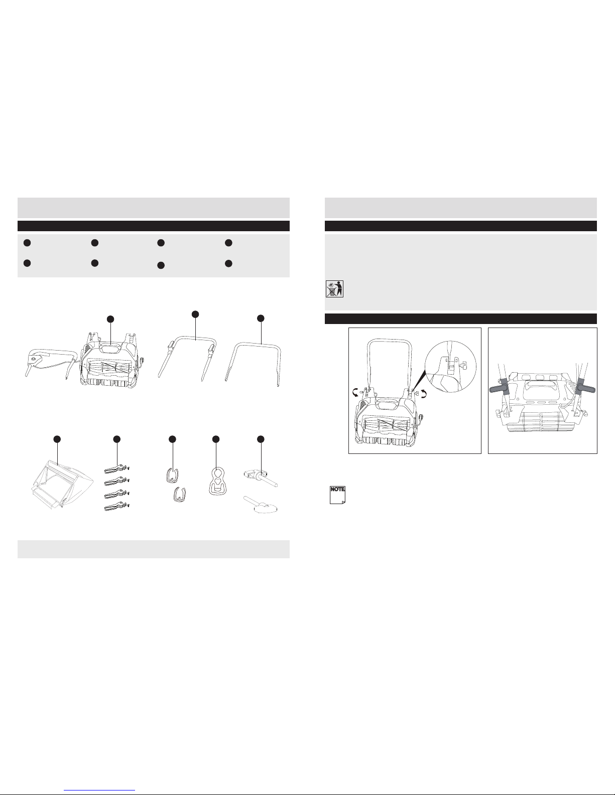
In the Box
Parts
A
1. Remove all parts of the rear roller cylinder mower from the box and carefully remove all
packaging. Take care not to lose any instructions which may be attached to the parts. These
provide important information which will be required while assembling the rear roller cylinder
mower.
2. Keep all packaging until the rear roller cylinder mower is fully assembled and has been
operated successfully.
Please keep original packaging for warranty purposes.
Locate the lower handle to the slot on deck, and tighten the xing screws on both side.
NOTE! Make sure that the cable hooks are at the back side of the machine.
Preparing to assemble the Rear Roller Cylinder Mower
Assembly
Step 1 - Assemble the lower handles
A
Main unit with upper
handle
B
Lower handle
C
Grass bag
D
CAM lever 4pcs
E
Cable clip, 2pcs
F
Cable retainer
G
Screw, 2pcs
H
Middle handle
B
H
D EC F G
If there are any parts missing, please call the customer helpline on 01904 727500
Page 4
76
Customer Helpline 01904 727500
www.gardenservicecentre.co.uk
Customer Helpline 01904 727500
www.gardenservicecentre.co.uk
Step 2 - Assembling the middle and upper handles
Assembly
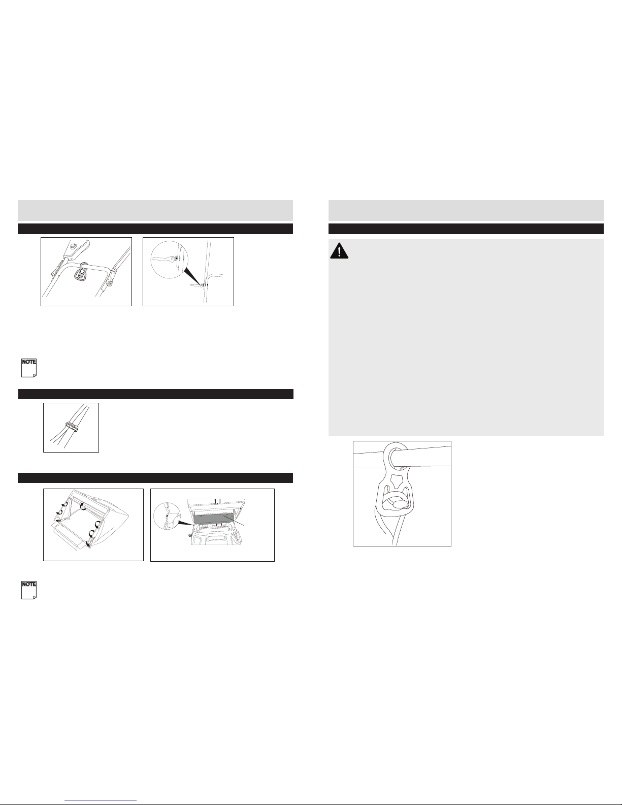
Step 3 Securing the power cord with cable clip
1. Secure the power cable to the frame using the cable clips. Use one clip on the middle handle
frame and the second on the lower handle frame.
Assembly
Step 4 - Fitting the grass box
1. Fix all of the P-Clip plastic extrusion over the metal frame.
2. When assembling the grass bag onto the machine, lift the front plastic cross strap and locate the
2pins into the slot holes on the deck.
Note: Make sure the extension plastic part is on the bar above front roller
Step 5 - Connection to the power supply
WARNING!
- Read all of the instructions of this manual before connecting the power supply for your tool.
- If the insulation on a power cable or extension lead is found to be cut or damaged, do not
touch it! Disconnect the power supply immediately and have the damaged cable replaced by
authorized service agent.
- If operating the appliance in a damp location is unavoidable, use a residual current device
(RCD) protected supply. Use of an RCD reduces the risk of electric shock.
- Use only extension cords suitable for outdoor use, preferably with a high visibility cable colour.
Always unwind all extension cables fully, coiled cables can overheat and reduce the efciency of
your product.
- For extension cables up to 15metres, use a wire cross section of 1.5mm
2
(cable diameter). For
extension cables over 15 meters but less than 40 meters, use a wire cross section of 2.5 mm
2
(cable diameter).
- This product is designed to operate on 230-240 VAC 50Hz. The voltage and current must
comply with the information on the ratings label!
- This rear roller cylinder mower is tted with a non-rewireable plug.If it is necessary to change
the fuse in the plug or the fuse cover become loose or damaged, the plug must not be used until
a suitable replacement is obtained.
- A 13amp fuse must be tted.
1. Make sure the on/off switch is in its off position.
2. Double the extension cord, about a foot from the end. Push the loop through the hole on the rear
safe guard and hook the loop over the cord restrainer. Gently pull on the cord to ensure that it is
rmly attached at the handle.
3. Connect the cord to a suitable socket.
1. Slide the cord retainer onto the middle handle, sliding it around to the top of the handle so it
does not fall off during the following assembly steps.
2. Slide the middle handle into the proled area of the lower handle frame. Make sure that the
holes of both sides off the upper handle are directly aligned with the holes of the frame.
3. Secure the upper handle to the middle handle frame with the CAM lever and bolts provided.
4. Repeat the above process on the upper and lower handle.
Note: Make sure that the switch box is on the same side as the cable from the deck and that
they are not twisted.
extension plastic
part
Assembling the Grass bag to the machineAssembling the Grass bag /frame
Page 5

8
Customer Helpline 01904 727500
www.gardenservicecentre.co.uk
Customer Helpline 01904 727500
Our dedicated UK based customer helpline is open 7 days a week to assist you with assembly,
parts queries and technical support. We are open during ofce hours but you can always send an
email via support@gardenservicecentre.co.uk. Our experts are here to get you back enjoying
your garden in no time.
For useful assembly, starting and maintenance videos and ordering spares please visit
www.gardenservicecentre.co.uk.
Calling our service does not affect your statutory rights
UK/Ireland 01904 727500
Monday to Friday 9am – 5pm, Saturday & Sunday 11am – 4pm
www.gardenservicecentre.co.uk
email: support@gardenservicecentre.co.uk
Getting Help
Page 6

Important - Please read these instructions fully before operating or maintaining your rear roller
cylinder mower.
These instructions contain important information that will help you get the best from your rear roller
cylinder mower, ensuring it is assembled correctly and safely.
Operation and Maintenance Manual
Qualcast
400W Rear Roller Cylinder Mower
SCM32A
Jan 2015 Rev A
Page 7

Important - Please read these instructions fully before operating or maintaining
3
Customer Helpline 01904 727500
www.gardenservicecentre.co.uk
Contents
2
Customer Helpline 01904 727500
www.gardenservicecentre.co.uk
Safety Information .............................................................................................................................................3
Warning Symbols ..........................................................................................................................................3
General Safety ..............................................................................................................................................5
Personal Safety ............................................................................................................................................5
Operational Safety ........................................................................................................................................6
Maintenance and Storage Safety ................................................................................................................7
Service .........................................................................................................................................................7
Preparing to Operate the cylinder mower .........................................................................................................8
Preparing to operate the cylinder mower .....................................................................................................8
Step 1 - Adjusting the cutting height .............................................................................................................8
Step 2 - Switch on /off...................................................................................................................................9
Step 3 - Adjusting the blade clearance .........................................................................................................9
Operating the cylinder mower .........................................................................................................................10
Operating ....................................................................................................................................................10
Maintenance and Repair .................................................................................................................................11
Storage and Transportation ............................................................................................................................11
Troubleshooting ..............................................................................................................................................13
Technical Data .................................................................................................................................................13
Recycling and Disposal ...................................................................................................................................13
Plug Replacement ...........................................................................................................................................14
Getting Help ....................................................................................................................................................15
Guarantee .......................................................................................................................................................16
Please read these instructions fully before operating or maintaining your rear roller cylinder mower.
Warning.
Read the instruction manual.
Conforms to all relevant safety standards.
Wear eye protection.
Wear ear protection.
Wear protective gloves.
Wear foot protection.
Do not expose to rain.
Keep bystanders away. Thrown objects can cause serious injury.
WARNING! Remove plug from the mains immediately if the cable is damaged or cut .
Warning Symbols
Safety Information
Page 8

Important - Please read these instructions fully before operating or maintaining
4
Important - Please read these instructions fully before operating or maintaining
5
Customer Helpline 01904 727500
www.gardenservicecentre.co.uk
Customer Helpline 01904 727500
www.gardenservicecentre.co.uk
WARNING!
- Keep this operating and maintenance manual in a safe place for future reference.
- Read the instructions carefully. Be familiar with the controls and the proper use of the equipment.
- Never allow children or people unfamiliar with these instructions to use the rear roller cylinder
mower. Local regulations can restrict the age of the operator.
- Never mow while people, especially children, or pets are nearby. Keep in mind that the operator or
user is responsible for accidents or hazards occurring to other people or their property.
- This appliance is not intended for use by persons (including children) with reduced physical,
sensory or mental capabilities, or lack of experience and knowledge, unless they have been
given supervision or instruction concerning use of the appliance by a person responsible for their
safety.
- Keep all bystanders, children, and pets at least 50 feet away. The operator or user is
responsible for accidents or hazards occurring to other people or the property.
General Safety
Safety Information
Double insulation.
SWITCH OFF! Remove plug from mains before cleaning or maintenance
Danger from damaged mains cable. Keep mains cables away from blades!
Danger of injury from rotating parts.The blades will continue to rotate after the tool has
been switched off. Wait for them to stop moving.
Electrical Tool Disposal! In accordance with European Directive 2002/96/EC on waste
electrical and electronic equipment and its implementation in national law. Electric tools
are collected separately and recycled environmentally. Take advantage of the collection
facilities. Ask your local council for the collection systems. If electrical appliances are
disposed incorrectly the environment can be poisoned as the hazardous substances enter
into the groundwater and entering the food chain, or ora and fauna.
Guaranteed sound power level .
Warning Symbols
96
Safety Information
- Use personal protective equipment (PPE). Always wear eye protection. Protective equipment
such as dust mask, non-slip safety shoes, hard hat, or hearing protection used for appropriate
conditions will reduce personal injuries.
- Dress appropriately. Do not wear loose clothing or jewellery, as these can be caught in moving
parts. Preferably wear non-slip footwear when working outdoors. Wear protective hair covering to
keep long hair out of the way.
- Stay alert, watch what you are doing and use common sense when operating a power
tool. Do not use a power tool while you are tired or under the inuence of drugs, alcohol or
medication. A lapse of concentration while operating power tools may result in serious personal
injury.
- Prevent unintentional starting. Ensure the switch is in the off-position before connecting to
power source, picking up or carrying the tool. Carrying power tools with your nger on the switch
or energising power tools that have the switch on invites accidents.
- Keep all parts of the body away from the cutting blades. Make sure the switch is off when
clearing jammed material. A moment of inattention while operating the cylinder mower may result In
serious personal injury.
- Do not overreach. Keep proper footing and balance at all times. This enables better control of
the power tool in unexpected situations.
- Do not touch the rotating blades until they are stopped.
Personal Safety
Page 9

Important - Please read these instructions fully before operating or maintaining
6
Important - Please read these instructions fully before operating or maintaining
7
Customer Helpline 01904 727500
www.gardenservicecentre.co.uk
Customer Helpline 01904 727500
www.gardenservicecentre.co.uk
Operation Safety
Safety Information
- Be certain the parts are fully tightened before operating the tool. Check periodically for
tightness during use to avoid serious injury.
- Risk of injury. Do not touch or try to stop the blades when they are moving.
- Disconnect the plug. Disconnect plug from the tool when not in use or when servicing or
cleaning.
- Check for damaged parts. Before further use, carefully check the tool for damage. Check for
alignment of moving parts, binding of moving parts, breakage of parts, mountings and any other
condition that may affect its operation. Do not use the tool if any parts are damaged or defective.
Have any damaged or defective parts repaired or replaced by an authorised service agent. Never
attempt any repairs yourself.
- Grip the tool securely. Always hold the tool securely in both hands while working with it.
- Keep handle dry, clean and free from oil and grease. Slippery handles do not allow for safe
handling and control of the tool in unexpected situations.
- Keep cable away form cutting area. During operation the cable may be hidden in shrubs and
can be accidentally cut by the blade.
- Do not overload the tool. Only work in the performance range stated. Do not use tools that do
not have sufcient power for heavy jobs. Do not use the tool for any use other than that intended
by the manufacturer.
- If there is any danger of slipping on sloped ground,have a second person secure the tool with a
rod or cable. The second person should stand up the slope at a safe distance from the tool.
- Avoid damage to the tool. Do not apply extra weight and do not drag the tool over hard
surfaces such as tiles or steps.
- Do not use the tool on excessively steep slopes. Make sure that you are standing rmly
when using the tool, especially on slopes. If working on a slope, work along the slope, not
upwards or downwards. Be particularly careful when changing direction on the slope.
- Do not use the power tool if the switch does not turn it on and off. Any power tool that
cannot be controlled with the switch is dangerous and must be repaired.
- Disconnect the plug from the power source before making any adjustments, changing or
storing power tools. Such preventive safety measures reduce the risk of starting the power tool
accidentally.
- The use of a residual current device (R.C.D) with a tripping current of not more than 30mA is
recommended.
- Use appropriate tool. This device is only intended for mowing the lawn in private house an
hobby gardens. Do not force small tools or attachments to do the job of a heavy duty tool.
- Keep work areas clean. Check the terrain on which the tool will be used, and remove stones,
sticks, wires or other foreign objects that may be caught up and spun off.
- Consider work area environment. Do not expose your tool to high humidity or rain. Do not
use your tool in damp and wet conditions. Keep the work area well lit.
Safety Information
- Do not operate power tools in explosive atmospheres, such as in the presence of
ammable liquids, gases or dust. Power tools create sparks which may ignite the dust or
fumes.
- Power tool plugs must match the outlet. Never modify the plug in any way. Do not use
any adapter plugs with earthed (grounded) power tools. Unmodied plugs and matching
outlets will reduce risk of electric shock.
- Avoid body contact with earthed or grounded surfaces, such as pipes, radiators. There is
an increased risk of electric shock if your body is earthed or grounded.
- Do not expose power tools to rain or wet conditions. Water entering a power tool will
increase the risk of electric shock.
- Do not abuse the cord. Never use the cord for carrying, pulling or unplugging the power tool.
Keep cord away from heat, oil, sharp edges or moving parts. Damaged or entangled cords
increase the risk of electric shock.
- When operating a power tool outdoors, use an extension cord suitable for outdoor use.
Use of a cord suitable for outdoor use reduces the risk of electric shock.
Operation Safety (continued)
- Maintain tools with care. Keep tools clean and in good condition for better and safer
performance. Follow the instructions for maintenance and changing accessories. Keep handles
and switches dry, clean and free from oil and grease.
- Be careful in handling the tool. Keep the cutting blades sharp and clean to improve its
working safety and effectiveness.
- Store idle power tools out of the reach of children and do not allow people unfamiliar
with the power tool or these instructions to operate the power tool. Power tools are
dangerous in the hands of untrained users.
Maintenance and Storage
- Have your tool repaired by an authorised service agent. This tool is manufactured in
accordance with the relevant safety regulations. To avoid danger, electrical appliances must only
be repaired by qualied technicians. If you require support or in need of spares or repair, please
contact the Garden Service Centre at 01904 727500.
Service
Page 10

98
Customer Helpline 01904 727500
www.gardenservicecentre.co.uk
Customer Helpline 01904 727500
www.gardenservicecentre.co.uk
Preparing to Operate the Cylinder Mower
Preparing to operate the rear roller cylinder mower
Always wear safety gloves when doing any work on the rear roller cylinder mower.
WARNING! Always unplug the power cord from the power source before doing any work on the
rear roller cylinder mower.
Step 1 Adjusting the cutting height
This Cylinder mower can be set to 3 positions of cutting height. Position 3 is the lowest cutting
height.
1. Pull the lever outwards from the machine and then select your required cutting height position
1-2-3.
2. Release the lever and then make sure that it is fully secured into the selected cutting position.
NOTE! Never use the lowest cutting height for the rst cut of the season or in drought conditions.
Cutting position Cutting height
1 18 mm
2 28 mm
3 38 mm
1
2
Step 2 - Switch on /off
CAUTION! For your safety, this tool is equipped with a double switch system. This system
prevents starting the tool inadvertently. You must press the switch lock button (A) rst before
pulling the switch lever (B).
WARNING! Never attempt to pull the switch level without pressing the switch lock button rst!
Preparing to Operate the Cylinder Mower
Step 3 - Adjusting the blade clearance
Cylinder mower blades act like a pair of shears and should be adjusted if the grass is not cut
cleanly and evenly.
1. Turn the mower upside down and using a screwdriver, turn each adjustment screw as shown
above, clockwise a little at a time.
A
B
C
D
Switching ON
1. Press the switch lock button (A).
2. Pull the switch lever (B) and release the switch button (A).
Switching OFF
Release the switch lever (B).
WARNING! Never adjust the blade while the machine is plugged into the main power source.
Page 11

1110
Customer Helpline 01904 727500
www.gardenservicecentre.co.uk
Customer Helpline 01904 727500
www.gardenservicecentre.co.uk
Preparing to Operate the Cylinder Mower
Operating
WARNING!
- Always keep a rm grip on the tool with both hands and watch your feet. The blades may cause
an accident. Be careful while moving backwards –danger of tripping!
To avoid damage to the tool:
- Never lift or drag the tool with the motor running.
- When mowing, do not allow the motor to labour particularly in heavy conditions.
- When the motor labours, the speed of the motor drops and you will hear a change in the motor
sound, you should stop the mowing immediately and release the switch lever and raise the height
of cut.
1. Place the cylinder mower on the edge of the lawn.
2. Always work away from the mains socket. Make sure that the cable is kept well away from the
working area.
NOTE: The blades may require adjustment, particularly before rst use—see Adjusting the
blades.
1
2
2. Wearing gloves, carefully rotate the cutting cylinder (C) by hand to ensure it very lightly
brushes across the whole width of the bottom blade. If the blades are too difcult to turn, slightly
loosen each adjustment screw (D).
3. While the blade reel is turning, insert a sheet of paper (thickness around 0.12mm) between
the blade reel and the cutting bar. The paper should shear evenly along the entire length of the
cutter bar, as if being cut by scissors. If the paper doesn’t shear, slightly tighten each adjustment
screw(B) and repeat the test.
4. Turn the mower back over, plug it and try it. It should now be giving a clean and even cut. If
not, unplug and re-adjust screws.
From time to time during use, it is advisable to carry out the above procedure to ensure that your
cylinder mower is always cutting at its best.
Step 3 - Adjusting the blade clearance (continued)
Operating the Cylinder Mower
Maintenance and Repair
Maintenance and Repair
WARNING! Always switch the product off and let the product cool down before performing
inspection, maintenance and cleaning work!
After every use
1. Clean the product with a slightly damp cloth and pH-neutral soap. Use a brush for areas that
are hard to reach.
2. Clean all of the rollers front and rear from grass/dirt debris. In particular clean the air vents with
a cloth and brush.
3. Remove stubborn dirt with high pressure air (max. 3 bar).
4. Check for worn or damaged parts. Replace worn parts as necessary or contact an authorised
service centre for repair before using the product again.
5. Check for obvious defects such as loose, dislodged or damaged cutting device, loose xings
and worn or damaged components.
6. Check that covers are undamaged and correctly tted. Carry out necessary maintenance or
repairs before using the product.
7. Regularly apply lubricant to mower’s cutting surface, cutting reel axle shaft and wheels.
Storage and Transportation
Storage
1. Clean the product as described above.
2. Store the product and its accessories in a dark, dry, frost-free, well-ventilated place.
3. Always store the product in an upright or horizontal position in a place that is inaccessible to
children. The ideal storage temperature is between 10 and 30°C.
4. We recommend using the original package for storage or covering the product with a suitable
cloth or enclosure to protect it against dust.
Page 12

1312
Customer Helpline 01904 727500
www.gardenservicecentre.co.uk
Customer Helpline 01904 727500
www.gardenservicecentre.co.uk
WARNING! Only perform the steps described within these instructions!
All further inspection, maintenance and repair work must be performed by an authorised service
centre or a similarly qualied specialist if you cannot solve the problem yourself!
Storage and Transportation
Cable tidy system
Handle positions storage
Transportation
1. Switch the product off and disconnect it from power supply before transporting it anywhere.
2. Always carry the product by the central carry handle.
3. Protect the product from any heavy impact or strong vibrations which may occur during
transportation in vehicles.
4. Secure the product to prevent it from slipping or falling over.
NOTE! Always carry the product by the central carry handle.
Suspected malfunctions, disturbances or damages are often due to causes that the user can
x themself. Therefore check the product using this section. In most cases the problem can be
solved quickly.
Problem Possible Cause Solution
Product does not
start
1. Not connected to power supply
2. Power connection is loosen
3. Other electrical defect to the
product
1. Connect to power supply
2.Connect the power supply and tool
well
3. Check by a specialist electrician
Product does not
reach full power
1. Extension cord not suitable for
operation with this product
2. Power source (e.g. generator)
has too low voltage
3. Machines internal wiring
damaged
1. Use a proper extension cord
2. Connect to another power source
3. Contact the customer helpline
Machine not cutting 1. Height of cut too low
2. Blades off cut
1. Increase height of cut (See -Adjusting the cutting height)
2.Blades require adjustment (See—
Adjusting the blades clearance)
Machine leaves
ragged nish
1.Cutting blades blunt Blade require adjustment (SeeAdjusting the blades clearance)
Cutting blades not
rotating
1.Cutting blades obstructed
2.Belt is slipping or is damaged
1.Clear obstruction
2.Contact customer helpline
Excessive vibration/
noise
1.Cutting blades damaged
2.Cutting blades not adjusted
evenly
1.Contact customer helpline
2.Blades require adjustment(SeeAdjusting the blades clearance)
Rollers do not rotate Roller is blocked by debris Clean all roller slots
Troubleshooting
General Troubleshooting
Technical Data Table
WARNING! The vibration emission value during actual use of the tool can differ from the declared
value depending on the ways in which the tool is used. Identify safety measures to protect the
operator that are based on an estimation of exposure in the actual conditions of use (taking
account of all parts of the operating cycle such as the times when the tool is switched off and when
it is running idle in addition to the trigger time).
The sound intensity level for the operator may exceed 85dB(A) and ear protection measures are
necessary.
Technical Data
After use, wrap your extension cable around the cable hooks and secure the plug in place.
To release the extension cable for machine use, just rotate the cable hook .
Push the lower handle to the right and then rotate forward, make sure the lower handle is out of
the block position. Release the CAM levers and fold the handle down.
cable clip
Handle operating
position
Handle - park
position
Page 13

1514
Customer Helpline 01904 727500
www.gardenservicecentre.co.uk
Customer Helpline 01904 727500
www.gardenservicecentre.co.uk
1. Recycle unwanted materials instead of disposing of them as waste. All tools, hoses
and packaging should be sorted, taken to the local recycling centre and disposed of in an
environmentally safe way.
2. Recycle rather than dispose of unwanted material in landll whenever possible. The machine
must be delivered in rigid packaging to avoid damage during transportation. The packaging and the
machine itself are manufactured from recyclable materials and should be disposed of accordingly.
3. Do not throw your clippings into a rubbish bin where it will be disposed of in landll.You can
dispose of clippings on your compost heap, alternating then with other garden material. The more
thoroughly you chop the clippings beforehand, the more rapidly they will degrade. Alternatively,
many communities provide a public collection point where you can dispose of your garden waste in
an environmentally friendly manner.
4. Only dispose of electrical/electronic/battery iterms in separate collection schemes, which cater
for the recovery and recycling of materials contained within. Your cooperation is vital to ensure the
success of these schemes and for the protection of the environment.
5. Recycle packaging where facilities exist.
6. This symbol is known as the Crossed out Wheelie Bin Symbol. When this symbol is marked on
a product or battery, it means that it should not be disposed of with your general household waste.
Some chemicals contained within electrical/electronic products or batteries can be harmful to
health.
Technical Data
Technical Data Table (continued)
Customer Helpline 01904 727500
Disposal Instructions
Our dedicated UK based customer helpline is open 7 days a week to assist you with assembly,
parts queries and technical support. We are open during ofce hours but you can always send an
email via support@gardenservicecentre.co.uk. Our experts are here to get you back enjoying
your garden in no time.
For useful assembly, starting and maintenance videos and ordering spares please visit
www.gardenservicecentre.co.uk.
Calling our service does not affect your statutory rights
UK/Ireland 01904 727500
Monday to Friday 9am – 5pm, Saturday & Sunday 11am – 4pm
Getting Help
Recycling and Disposal
Plug Replacement
Plug Replacement
Your rear roller cylinder mower is tted with a moulded plug. However If you need to replace a tted
plug then follow the instructions below.
IMPORTANT
The wires in the mains lead are coloured in accordance with the following code:
Blue - Neutral Brown – Live
As the colours of the wires in the mains lead of this appliance may not correspond with the coloured
markings identifying the terminals in your plug, proceed as follows.
The wire which is coloured blue must be connected to the terminal which is marked with N
The wire which is coloured brown must be connected to the terminal which is marked with the letter
L
If a 13AMP (BS1363/A) plug is used, a 13A fuse must be tted, or if any other type of plug is used a
13AMP fuse must be tted, either in the plug or adapter, or on the distribution board.
Note: If a moulded plug is tted and has to be removed take great care in disposing of the plug
and severed cable, it must be destroyed to prevent engaging into a socket. If the supply cord is
damaged it must be replaced by a service agent or a similarly qualied person in order to avoid
hazard.
Property Value
Motor Voltage 230-240V ~/50Hz
Power Input 400 W
No-load speed 3700 rpm
Cutting width 320 mm
Height of cut 18mm/28mm/38mm
Net Weight 12 kg
Measured sound pressure level 74 dB(A), k=4 dB(A)
Measured sound power level 94 dB(A), k=4 dB(A)
Guaranteed sound power level 96 dB(A)
Vibration (m/s
2
) 2.323 m/s2 K=1.5 m/s
2
The declared vibration value has been measured in accordance with a standard test method and
may be used for comparing one tool with another. The declared vibration value may also be used in
a preliminary assessment of exposure.
Page 14

16
Customer Helpline 01904 727500
www.gardenservicecentre.co.uk
Guarantee
Dear Customer,
In the unlikely event that your device develops a fault, please contact our Customer service
department on the telephone number shown below.
1. These guarantee terms cover additional guarantee rights and do not affect your statutory
warranty rights.
Claims must be accompanied by Proof of Purchase. This must be in the form of a Sales receipt
or Bank statement and must show that the product has been purchased within 2 year prior to the
claim, from the retailer that it was originally sold to.
2. Our guarantee covers problems caused by material or manufacturing defects, and will result
in the repair of these defects or replacement of the device with a like for like or similar article.
Please note that our devices have not been designed for use in commercial, trade or industrial
applications. Consequently, the guarantee is invalidated if the equipment is used in commercial,
trade or industrial applications or for other equivalent activities.
3. The following are also excluded from our guarantee:
A) Faults due to accidents, customer misuse, or unauthorized repairs
B) Consumable Parts such as Blades
C) Failure due to lack of routine maintenance
D) Failure as a result of not using the equipment in accordance with the manual and safety
instructions
E) The adjustment of cables, drive belts
4. The guarantee is valid for a period of 2 year starting from the purchase date of the device.
Guarantee claims should be submitted before the end of the guarantee period within two weeks
of the defect being noticed. No guarantee claims will be accepted after the end of the guarantee
period. The original guarantee period remains applicable to the device even if repairs are carried
out or parts are replaced. In such cases, the work performed or parts tted will not result in
an extension of the guarantee period, and no new guarantee will become active for the work
performed or parts tted. This also applies when an on-site Service is used.
5. Please keep your sales receipt in a safe place. If the defect is covered by our guarantee your
device will either be repaired under the terms of guarantee or we will send you a replacement
device. This device may be re-conditioned or like for like replacement.
 Loading...