

Page 1
GB • Printed in England • BA F 016 L69 881 • Powertrak 340 • OSW 02.10
F016 L69 881 - GB Seite 1 Freitag, 8. November 2002 9:25 09
TYP F016 xxx xxx
Made in UK.
Atco-Qualcast Stowmarket
1
2
3
3
4
5
6
7
8
LBA
3
96
579 230V ~ 50/60Hz XXXXW
xx.xx kg
xxxx 1/min
IPX4
xxxxxxxxxxxx
20xx
21
STOP
11 10 9
Suffolk Punch E 34
Powertrak 34/400
Page 2
1
2
3
4
5
6
7
8
9
GB • Printed in England • BA F 016 L69 881 • Powertrak 340 • OSW 02.10
F016 L69 881 - GB Seite 2 Freitag, 8. November 2002 9:25 09
Product Specification
Lawn Mower Qualcast Qualcast Suffolk Punch
Part number (typ) F016 508 042 F016 511 042 F016 513 042
Rated power 1200 W 1700 W 1200 W
Maximum blade width 34 cm 40 cm 34 cm
Height of cut 20–70 mm 20–70 mm 20–70 mm
Grassbox capacity 40 l 50 l 40 l
Weight 12,0 kg 14,0 kg 12,5 kg
Protection class / II / II / II
Serial Number See serial no. 21 (rating plate) on machine
Power-Trak 34 Power-Trak 400 E34
Intended Use
This product is intended for domestic lawn
mowing.
Introduction
This manual gives instructions on the correct
assembly and safe use of your machine. It is
important that you read these instructions
carefully.
When fully assembled the machine weighs
approximately 12 kg to 14 kg. If necessary,
obtain assistance to remove from packaging.
Take care when carrying the mower to the
lawn, as the blades are sharp.
Delivered Items
Carefully remove the machine from its packaging and check that you have all the following items:
– Lawnmower with handle assembly
– 1 Handle bottom
– 2 Bolts
– 2 Wing nuts
– 2 Screws
– 2 Grassbox parts (3 for 40 models only)
– 2 Cable clips
– Operating instructions
When parts are missing or damaged, please contact
the consumer care hotline on (01449) 742130 for assistance. We also have a network of Atco-Qualcast Approved Service Agents who you can contact for service and advice both within and outside the period of
guarantee.
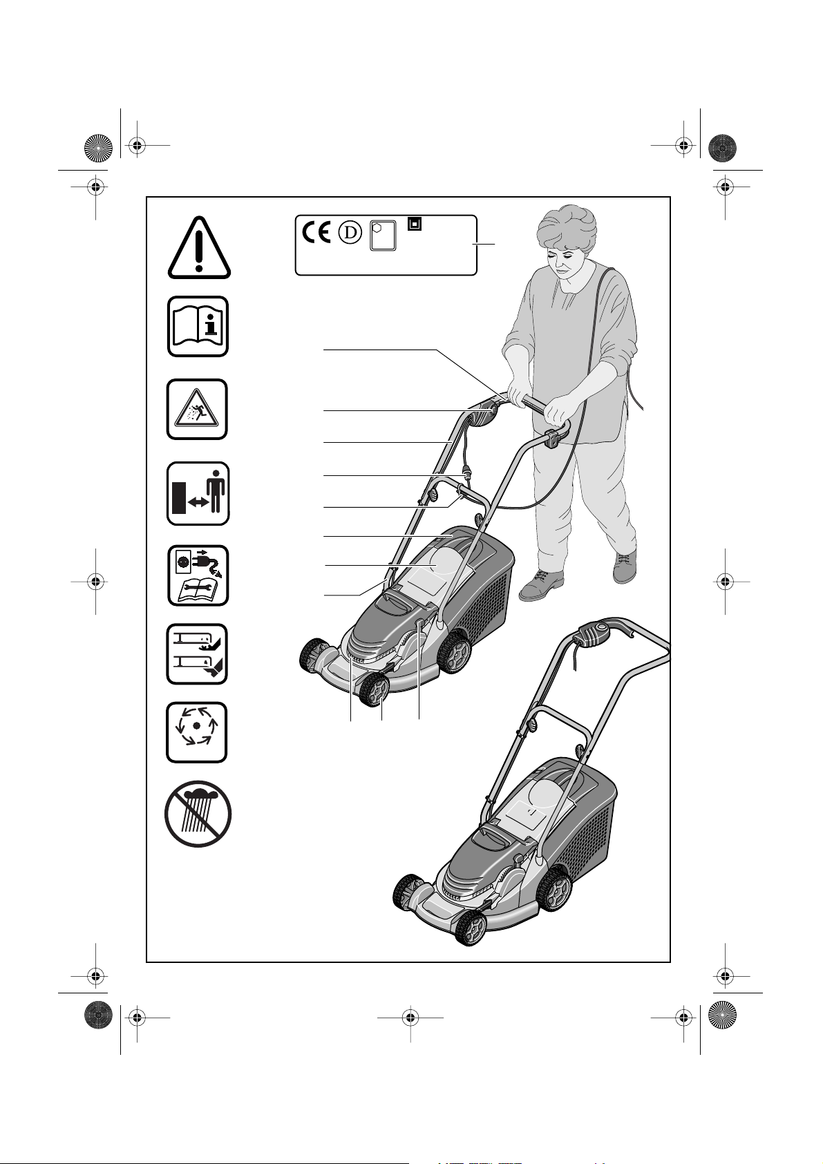
Operating Controls
Switch lever
Safety button
Handle top
Mains plug**
Cable restraint**
Grassbox
Deflector guard
Handle bottom
Ventilation slots
10 Wheels
11 Height of cut lever
**Country specific
Not all of the accessories illustrated or described are
included as standard delivery.
For Your Safety
Warning! Switch off, remove plug from mains
before adjusting, cleaning or if cable is cut,
damaged or entangled.
The blades continue to rotate for a few seconds after the machine is switched off.
Caution - do not touch rotating blades.
Electrical Safety
Your machine is double insulated for safety
and requires no earth connection. The operating Voltage is 230 V ac, 50 Hz. Only use an
approved extension cable. Contact your
service agent for details.
Extension cords/leads should only be used if
they comply with H05VV-F or H05RN-F types.
It is recommended for increased electrical
safety to use a Residual Current Device
(RCD) with a tripping current of not more
than 30 mA. Always check your RCD every
time you use it.
Page 3
F
0
I
2
1
4
3
I
5
6 .
6
6
7
1
2 .
GB • Printed in England • BA F 016 L69 881 • Powertrak 340 • OSW 02.10
F016 L69 881 - GB Seite 3 Freitag, 8. November 2002 9:25 09
For Product not sold in GB:
WARNING: For safety, it is essential that the
mains plug
to the power supply cable
The couplings of connection leads must be
protected against splashes and the coupling
sockets on the leads must be made of rubber
or coated with rubber.
Fixing means for the connection leads must
be used.
The connection lead must be inspected for
signs of damage at regular intervals and may
only be used if in perfect condition.
If the supply cord is damaged it must be replaced by a Atco-Qualcast approved service agent.
Products sold in GB only: Your mower is fitted
with an approved 13 A (BS1363/A) electric
plug and is protected by a 13 A fuse (ASTA
Approved to BS 1362).
If the fitted plug is not suitable for your socket
outlets, it should be cut off and an appropriate plug fitted in its place.
The severed plug must be disposed of to
avoid a possible shock hazard and should
never be inserted into a 13 A socket elsewhere.
attached to the machine is fitted
12 as in figure B .
Assembly
Handle assembly (see figure )
Insert the handle bottom 8 into the holes
➊
provided and
secure with the screws.
➋
Note: The handle top
Fix handles in desired position
Attach the handle top 3 with the bolts and
➌
wing nuts
Note: Ensure that the cable clips supplied are
used to fix the cable to the handle.
Attach cable to cable restraint
that sufficient cable slack is available. (non
GB models) (see figure )
Grassbox assembly
34 Models (see figure
Snap the grassbox top on the grassbox bottom by pushing all the "snap fits" together
around the edges starting at rear and working towards the front.
40 Models
Snap the grassbox bottom halves together
➊
by pushing all the "snap fits" together
around the edges starting at rear and
working towards the front.
13 to the handle bottom 8 .
) :
(see figure )
A
is height adjustable.
or II .
ensuring
B
C
:
D
Snap the grassbox top on the bottom as
➋
above.
Ensure cables are not trapped when folding/unfolding top handles, do not drop the
handles.
Grassbox (see figure )
Fitting
Lift the deflector guard 7 and hold up, fit the
grassbox
Removing/Emptying
Lift the deflector guard 7 and hold up. Remove grassbox
For non grass collection the mower can be
used without the grassbox
the deflector guard
.
in the down position.
E
in position, with
Adjusting the Cutting Height
(see figure )
Stop and remove the plug and wait until
the motor stops before adjusting height.
The blades continue to rotate after the
machine is switched off, a rotating
blade can cause injury.
For the first cutting of the season, a high cutting adjustment should be selected.
The lawnmower can be set to 11 cutting
heights between 20 mm and 70 mm. For this
purpose, press the height of cut lever
wards then lift or push down the mower until
the required height is selected.
11 out-
Starting and Stopping
The blade(s) continues to rotate for a
few seconds after the machine is
switched off. Allow the motor/blade to
stop rotating before switching “on”
again.
Do not rapidly switch off and on.
To aid starting tilt mower to side.
Starting (see figure ):
Press and hold the safety button 2 .
Squeeze the switch lever
the
handle.
Release the safety button
Stopping (see figure ):
Release the switch lever 1 .
G
towards
G
Page 4

GB • Printed in England • BA F 016 L69 881 • Powertrak 340 • OSW 02.10
F016 L69 881 - GB Seite 4 Freitag, 8. November 2002 9:25 09
3
A
I
➌
B
C
II
CLICK!
8
13
8
➊
➋
5
products not sold in GB
D
CLICK!
➋
➊
4
CLICK!
➊
12
CLICK!
E
7
6
F
11
Page 5

GB • Printed in England • BA F 016 L69 881 • Powertrak 340 • OSW 02.10
F016 L69 881 - GB Seite 5 Freitag, 8. November 2002 9:25 09
G
I
➊
2
➋
1
H
0
2
1
I
➊
17 17
➋
J
20
18
400 models
19
16
14 15
Page 6

GB • Printed in England • BA F 016 L69 881 • Powertrak 340 • OSW 02.10
F016 L69 881 - GB Seite 6 Freitag, 8. November 2002 9:25 09
J
J
9
Mowing
Place the lawnmower on the edge of the
lawn, as close to the power point as possible.
Work away from the power point. Then at
right angles. (see figure )
Position the cable to opposite side (already
cut) at the end of each turn.
When mowing
particularly in heavy conditions.
labour
When the motor labours the speed of
the motor drops and you will hear a
change in the motor sound, when this
occurs stop mowing, release the switch
lever and
to do so could damage the machine.
NOTE: The motor is protected by a safety cut
out which is activated when the blade becomes jammed or if the motor is overloaded.
When this occurs stop, remove the plug from
the power supply. The safety cut out will only
reset when the switch lever 1 is released.
Clear any obstruction and wait for a few minutes for the safety cut out to reset before continuing to use the mower. At this time do not
operate the switch lever 1 as this will prolong
the reset time of the safety cut out. If the
mower cuts out again increase the height of
cut to reduce the load on the motor.
Suffolk Punch E34 only:
The collection indicator 17 during normal operation will be in the raised position. When the
grassbox needs emptying or the chute
18 on the underside of the mower is
area
blocked and requires cleaning, the indicator
will drop.
raise the height of cut . Failure
(see figure )
I
do not allow the motor to
H
J
Maintenance
Stop, remove plug from the power supply and remove the grassbox.
Note: To ensure long and reliable service,
carry out the following maintenance regularly.
Regularly check for obvious defects such as
a loose, dislodged or damaged blade, loose
fixings, and worn or damaged components.
Check that covers and guards are undamaged and correctly fitted. Carry out necessary maintenance or repairs before using.
If the mower should happen to fail despite
the care taken in manufacture and testing,
repair should be carried out by a Atco-Qualcast Approved Service Agent.
For all correspondence and spare parts orders, always include the 10-digit (typ) part
number from the nameplate of the machine!
Blade Maintenance (see figure )
Stop, remove plug from the power supply and remove the grassbox.
Turn the machine on its right side and inspect
the blade; if blunt or damaged, replace.
Use the following procedure to remove and
replace the blade.
34 models:
Hold the blade 15 using gardening gloves
(not provided) use a spanner (not provided)
to remove the blade bolt
16 and blade.
washer
Fit the blade, blade washer and the blade
bolt. Ensure that the blade is the correct way
up (so that this symbol can be seen located as in figure
firmly.
400 models:
Use the following procedure to remove and
replace the blade. Hold the blade
gardening gloves (not provided) use a spanner (not provided) to remove the blade
14 , blade washer 16 , bevel washer 19
bolt
and blade. Fit the bevel washer, blade,
blade washer and the blade bolt. Ensure that
the blade is the correct way up (so that this
symbol can be seen located as in figure
and tighten the bolt firmly.
All models:
In the event of a blade becoming difficult to
remove or fit, insert a screwdriver into hole
to lock the drive. Ensure the screwdriver is removed before attempting to turn the machine on.
) and tighten the bolt
J
14 , blade
15 using
20
After Mowing/Storage
Clean the exterior of the machine thoroughly
using a soft brush and cloth.
solvents or polishes
debris, especially from the ventilation slots
Turn the machine on its right side and clean
the blade area. If grass cuttings are compacted in the blade area, remove with a
wooden or plastic implement.
Store the machine in a dry place. Do not
place other objects on top of the machine.
To aid storage loosen the wing nuts
fold the handles.
Ensure cables are not trapped when folding/unfolding top handles, do not drop the
handles.
. Remove all grass and
Do not use water,
13 and
)
.
Page 7

GB • Printed in England • BA F 016 L69 881 • Powertrak 340 • OSW 02.10
F016 L69 881 - GB Seite 7 Freitag, 8. November 2002 9:25 09
Fault Finding
The following table gives checks and actions that you can perform if your machine does not
operate correctly. If these do not identify/remedy the problem contact a Qualcast Approved
Service Agent.
Warning: Switch off, remove plug from mains before investigating fault.
Symptom Possible Cause Remedy
Machine fails to
operate
Machine functions
intermittently
Machine leaves
ragged finish or
motor labours
Cutting blade not
rotating
Excessive vibration/noise
Power turned off
Mains socket faulty
Extension cable damaged
Fuse faulty/blown
Mower in long grass
Motor protector has activated
Extension cable damaged.
Machines internal wiring damaged
Motor protector has activated
Height of cut too low
Cutting blade blunt
Underside of machine badly
clogged
Blade fitted upside down
Cutting blade obstructed
Blade nut/bolt loose
Blade nut/bolt loose
Cutting blade damaged
Turn power on
Use another socket
Inspect cable, replace if damaged
Replace fuse
Increase height of cut and tilt
mower
Allow to cool and increase
height of cut
Inspect cable, replace if damaged
Contact your service agent
Allow to cool and increase
height of cut
Increase height of cut
(see Height of Cut Adjustment)
Replace blade
(see Blade Maintenance)
Clean machine
(see After Mowing/ Storage)
Refit blade correctly
(see Blade Maintenance)
Clear obstruction
Tighten blade nut/bolt
Tighten blade nut/bolt
Replace blade
Page 8

GB • Printed in England • BA F 016 L69 881 • Powertrak 340 • OSW 02.10
F016 L69 881 - GB Seite 8 Freitag, 8. November 2002 9:25 09
Declaration of Conformity
Measured values determined according to
2000/14/EC (1.60 m height, 1 m distance
away) and EN 25 349.
34 Models: Typically the A-weighted noise
level of the product is: sound pressure level
84 dB (A); sound power level 95 dB (A).
400 Model: Typically the A-weighted noise
level of the product is: sound pressure level
85 dB (A); sound power level 96 dB (A).
The typical hand/arm vibration is below
2.5 m/s
2
.
We declare under our sole responsibility that
this product is in conformity with the following
standards or standardization documents:
EN 60 335, EN 836 according to the provisions
of the directives 89/336 /EEC, 98/37 /EC,
2000/14/EC.
2000/14/EC: The guaranteed sound power
level L
assessment procedure according to An-
is lower than 96 dB (A). Conformity
WA
nex VI.
Notified body: SRL, Sudbury England
PLACE: Stowmarket, 01.02.2002
Signature: Director
Guarantee
Atco-Qualcast guarantees this product
against manufacturing defects. We will repair
(or replace at our option) if a manufacturing
defect occurs within the guarantee period as
long as it has only been subjected to domestic use.
For the purpose of this guarantee, domestic
use means any use of the product on the
property belonging to the purchaser and
forming part of the garden area of his/her
dwelling.
The guarantee period is 5 years parts and
2 years labour costs from date of purchase.
To obtain a repair under this guarantee:
• Take the product to an approved service
agent.
• Show your dated proof of purchase.
• Show this guarantee.
The guarantee does not apply if:
i. You cannot provide dated proof of pur-
chase.
ii. The product has been resold by the original
purchaser (this does not apply in the Republic of Ireland), or has been used under hire.
iii. The product has been modified to change
the manufacturers specifications, or if non
genuine replacement parts have been fitted.
iv. Any previous repair was undertaken by any-
one other than an approved service agent.
v. The fault is due to maladjustment, abuse, ne-
glect or accidental damage.
vi. The fault is due to lack of lubrication or main-
tenance.
vii. Damage to any part, particularly the drive
or cutting mechanism has been caused by
allowing the product to strike solid objects.
viii. The product develops a fault due to abnor-
mal use.
ix. Failure is due to normal wear. The following
parts are considered as wearing parts. Their
life is dependant on regular servicing and
they are not therefore, normally covered by
the guarantee:
Blades
Bearings
Cables
The cost of routine maintenance of the product is not covered by the guarantee.
It is in your best interest to follow the Operating Instructions for your machine, as a properly cared for product should give many
years of excellent service.
Should you require replacement parts, always insist on genuine Atco-Qualcast replacement parts. Any damage caused to
the product through the fitting of parts not
made by Atco-Qualcast is not covered by
the guarantee.
Your statutory rights are not affected by this
guarantee.
Environmental Information
Your product has been manufactured under
an environmental management system using, when possible, the most environmentally
responsible materials and processes, and
with the potential for recycling at the end of
its life. The packaging is also recyclable.
The plastic components are labelled for categorized recycling.
When the time comes to dispose of this product please consider the environment and
take it to a recognised recycling facility.
(Please contact your local authority for location information).
Page 9

GB • Printed in England • BA F 016 L69 881 • Powertrak 340 • OSW 02.10
F016 L69 881 - GB Seite 9 Freitag, 8. November 2002 9:25 09
Safety Notes
Warning! Read these instructions carefully, be familiar with the controls and
the proper use of the lawnmower.
Explanation of symbols on the lawnmower
General hazard safety alert.
Read instruction manual.
Beware of thrown or flying objects to bystanders.
Keep bystanders a safe distance away
from the machine.
Switch off and remove plug from mains
before adjusting, cleaning or if the cable is entangled and before leaving the
lawnmower unattended for any period.
Keep the supply flexible cord away
from the cutting blade.
Sharp blade(s). Beware of severing toes
or fingers.
Wait until all machine components
have completely stopped before
touching them. The blades continue to
STOP
rotate after the machine is switched off,
a rotating blade can cause injury.
Do not mow in the rain or leave the
lawnmower outdoors whilst it is raining.
Never allow children or people unfamiliar with
these instructions to use the lawnmower. Local
regulations may restrict the age of the operator.
Never mow while people, especially children or
pets, are nearby.
The operator or user is responsible for accidents
or hazards occurring to other people or their
property.
Do not operate the lawnmower when barefoot
or wearing open sandals, always wear substantial footwear and long trousers.
Thoroughly inspect the area where the lawnmower is to be used and remove all stones,
sticks, wires, bones and other foreign objects.
Before using, always visually inspect to see that
the blade, blade bolt and cutter assembly are
not worn or damaged or loose.
Replace worn or damaged blades and bolts in
sets to preserve balance.
Mow only in daylight or in good artificial light.
Avoid operating the lawnmower in wet grass,
where feasible.
Walk, never run.
Mowing on banks can be dangerous:
– Do not mow excessively steep slopes.
– Always be sure of your footing on slopes or
wet grass.
– Mow across the face of slopes - never up and
down.
– Exercise extreme caution when changing di-
rection on slopes.
– Use extreme caution when stepping back or
pulling the lawnmower towards you. Never
cut grass by pulling the mower towards you.
Stop the blades if the lawnmower has to be
tilted for transportation when crossing surfaces
other than grass and when transporting the
lawnmower to and from the area to be mowed.
Do not tilt the lawnmower when starting or
switching on the motor, except if the lawnmower has to be tilted for starting in long grass.
In this case, do not tilt it more than absolutely
necessary and lift only the part which is away
from the operator. Always ensure that both
hands are in the operating position before returning the mower to the ground.
Switch on the lawnmower with feet well away
from the blades.
Do not put hands or feet near or under rotating
parts.
Never pick up or carry the lawnmower while the
motor is running.
Remove the plug from the socket:
– whenever you leave the machine
– before clearing a blockage
– before checking, cleaning or working on the
lawnmower
– after striking a foreign object. Inspect the
lawnmower for damage and make repairs as
necessary
– if the lawnmower starts to vibrate abnormally
(check immediately).
Keep all nuts, bolts and screws tight to be sure
that the lawnmower is in safe working condition.
Replace worn or damaged parts for safety.
Ensure replacement parts fitted are AtcoQualcast approved.
Atco-Qualcast Ltd, Suffolk Works, Stowmarket, Suffolk, IP14 1EY, England
Printed in England F016L69881 (02.10)
Tel: (01449) 742130 Fax: (01449) 674243
Page 10

GB • Printed in England • BA F 016 L69 881 • Powertrak 340 • OSW 02.10
F016 L69 881 - GB Seite 10 Freitag, 8. November 2002 9:25 09
Electric Rotary Mower 34/40
OPERATING INSTRUCTIONS
 Loading...