

Page 1

Important - Please read these instructions fully before starting assembly
These instructions contain important information that will help you get the best from your
Rotavator, ensuring it is assembled correctly and safely.
If you need help or have damaged or missing parts, call the Customer Helpline on 0845 034 2279
prior to returning product to store.
Assembly Manual
Qualcast
149.3cc Petrol Rotavator
Complete Product
Support & Aftersales Service
HST-1003A
Scan to watch
our new quick
start videos!
Sep 2012 Rev A
Complete Product Support &
Aftersales Service 7 days a week.
Do you need help with this product?
Instead of returning your product please
call 0845 034 2279 7 days a week.
Email: support@gardenservicecentre.co.uk
Or visit www.gardenservicecentre.co.uk
This does not affect your statutory rights.
Page 2

Important - Please read these instructions fully before starting assembly
3
Customer Helpline 0845 034 2279
www.gardenservicecentre.co.uk
Contents
2
Customer Helpline 0845 034 2279
www.gardenservicecentre.co.uk
Safety Information .............................................................................................................................................3
Warning Symbols ..........................................................................................................................................3
General Safety ..............................................................................................................................................3
Personal Safety ............................................................................................................................................3
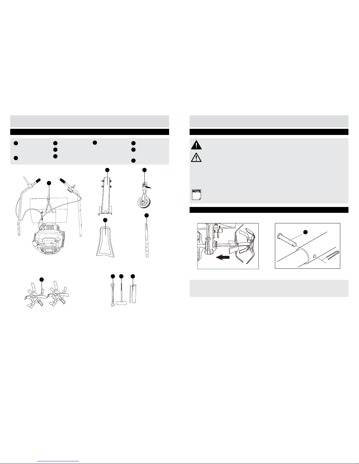
In the Box ..........................................................................................................................................................4
Parts ..............................................................................................................................................................4
Tools ..............................................................................................................................................................4
Assembly ...........................................................................................................................................................5
Preparing to assemble the petrol rotavator ..................................................................................................5
Step 1 ............................................................................................................................................................5
Step 2 ............................................................................................................................................................6
Step 3 ............................................................................................................................................................6
Step 4 ............................................................................................................................................................7
The following warning symbols appear throughout this assembly manual and indicate the appropriate
safety measures you should take when assembling and operating the petrol rotavator.
This symbol indicates there is a danger of serious personal injury or death if you do not observe the
warning.
This symbol indicates that there is a danger of damaging your hands if you do not wear thick,
protective gloves.
Warning Symbols
General Safety
Personal Safety
WARNING! Keep this assembly manual in a safe place for future reference.
WARNING! Always ensure anyone intending to operate this petrol rotavator is fully conversant
with the content of this assembly manual prior to assembling, maintaining or operating the petrol
rotavator.
WARNING! Perform assembly operations described in this manual .Failure to observe this warning
may lead to serious injury, death, or damage to the petrol rotavator.
WARNING! Always take care when removing the packaging to prevent damage to you or to the
petrol rotavator.
IMPORTANT! Before assembling the petrol rotavator, check all the parts indicated in the manual
are in the box. Inspect all the parts for signs of damage. Do not assemble the petrol rotavator if you
observe any damaged components.
WARNING! Only operate the petrol Rotavator if you are wearing the correct Personal Protective
Equipment (PPE)as described in the following warnings.
WARNING! Always wear suitable gloves when operating petrol rotavator to protect your hands
from ying debris and/or sharp objects.
Safety Information
Page 3
54
Customer Helpline 0845 034 2279
www.gardenservicecentre.co.uk
Customer Helpline 0845 034 2279
www.gardenservicecentre.co.uk
A
Main unit (with
upper handle
attached)
B
Handle bar support
C
Face plate
D
Front support wheel
E
Draw bar
F
Blade assembly
2pcs
1
Hexagonal spanner
2
Spanner and screw
driver
3
Spark plug spanner
In the Box
Parts
Tools
WARNING! Always take care when removing the packaging to prevent damage to you or to the
petrol rotavator.
IMPORTANT! Before assembling the petrol rotavator, check all the parts indicated in the manual
are in the box. Inspect all the parts for signs of damage. Do not assemble the petrol rotavator if
you observe any damaged components.
1. Remove all parts of the petrol rotavator from the box and carefully remove all packaging. Take
care not to lose any instructions which may be afxed to the parts. These provide important
information which will be required while assembling the petrol rotavator.
2. Keep all packaging until the petrol rotavator is fully assembled and has been operated
successfully.
NOTE! Always recycle the packaging in accordance with local recycling schemes.
1a Put the device on the ground. Fit the rotavator assembly over the axle.
1b Fix the split pin (A).
Preparing to assemble the petrol rotavator
Assembly
Step 1 - Fitting the Rotavator assembly
1a
1b
A
B
C
D
E
F
1 2 3
A
Page 4

76
Customer Helpline 0845 034 2279
www.gardenservicecentre.co.uk
Customer Helpline 0845 034 2279
www.gardenservicecentre.co.uk
Step 2 - Fitting the front wheel
Assembly
Screw the front wheel unit (B) to the machine (C) with the hexagonal bolt and nut as shown.
Pull the front wheel from its rest position. Attach the tension spring (D).
Step 3 - Fitting the draw bar
Assembly
Step 4 - Fitting the handle bar support
Hold the handle bar support (K) on the frame.
Tighten four hexagonal bolts with washers.
Pull out the securing splint (E) and the pin (F).
Insert the draw bar (G) into the main plate (H).
Insert the pin and secure it with the R/clip (E).
Step 5 - Fitting the steering handles
Hold both steering shafts at the side of the device, and insert two hexagonal bolts with washers into
each.
Tighten the hexagonal bolts.
Fit the steering cover on and screw it on tightly with four tapping screws.
NOTE! Make sure the clutch control lever (L) is at your right hand side when you stand behind the
unit.
B
C
D
E
G H
F
K
I
J
L
Page 5

Important - Please read these instructions fully before operating or maintaining your lawnmower
Operation and Maintenance Manual
These instructions contain important information that will help you get the best from your rotavator,
ensuring it is assembled correctly and safely.
If you need help or have damaged or missing parts, call the Customer Helpline on 0845 034 2279
prior to returning product to store.
Qualcast
149.3cc Petrol Rotavator
Complete Product
Support & Aftersales Service
HST-1003A
Sep 2012 Rev A
Scan to watch
our new quick
start videos!
Complete Product Support &
Aftersales Service 7 days a week.
Do you need help with this product?
Instead of returning your product please
call 0845 034 2279 7 days a week.
Email: support@gardenservicecentre.co.uk
Or visit www.gardenservicecentre.co.uk
This does not affect your statutory rights.
Page 6

Important - Please read these instructions fully before operating or maintaining
3
Customer Helpline 0845 034 2279
www.gardenservicecentre.co.uk
Contents
2
Customer Helpline 0845 034 2279
www.gardenservicecentre.co.uk
Safety Information .............................................................................................................................................3
Warning Symbols ..........................................................................................................................................3
General Safety ..............................................................................................................................................4
Training .........................................................................................................................................................4
Preparation ...................................................................................................................................................4
Operation ......................................................................................................................................................5
Maintenance and Storage ...........................................................................................................................6
Special Safety Instructions ...........................................................................................................................6
Preparing to Operate the Petrol Rotavator .......................................................................................................7
Step 1 - Commissioning ...............................................................................................................................7
Step 2 - Filling with Fuel ...............................................................................................................................9
Step 3 - Filling with Engine Oil......................................................................................................................9
Operating the Petrol Rotavator .......................................................................................................................10
Step 1 - Check before Use .........................................................................................................................10
Step 2 - Starting the Engine .......................................................................................................................10
Step 3 - Rotovating .....................................................................................................................................11
Maintenance ....................................................................................................................................................12
List of Vulnerable Parts ...............................................................................................................................12
leaning and Maintenance ...........................................................................................................................12
Replace Worn or Damaged Parts for Safety ..............................................................................................13
Store ...........................................................................................................................................................14
Troubleshooting ..............................................................................................................................................15
Technical Data .................................................................................................................................................17
Guarantee .......................................................................................................................................................18
Declaration of Conformity ...............................................................................................................................19
The following warning symbols appear throughout this manual and indicate the appropriate safety
measures you should take when operating and maintaining the rotavator.
Before any use, refer to the corresponding paragraph in the present manual.
This symbol, before a safety comment, indicates a precaution, a warning or a danger. Ignoring
this warning can lead to an accident for yourself or for others. To limit the risk of injury, re, or
electrocution always apply the recommendations indicated.
Conforms to European standards.
Danger of injury from ying parts!
Always maintain a sufciently safe distance.
Danger of injury from rotating parts!
Remove the ignition cable before all maintenance work, and read the instructions for use.
Take care when handling fuel and lubricants!
Wear hearing protection and eye protection when using the device.
Wear robust footwear when using the device.
Wear protective gloves when using the device.
Warnings Symbols
Safety Information
Page 7

Important - Please read these instructions fully before operating or maintaining
4
Important - Please read these instructions fully before operating or maintaining
5
Customer Helpline 0845 034 2279
www.gardenservicecentre.co.uk
Customer Helpline 0845 034 2279
www.gardenservicecentre.co.uk
WARNING! Keep this operating and maintenance manual in a safe place for reference at a later
date.
WARNING! Read the instructions carefully. Be familiar with the controls and the proper use of the
equipment.
WARNING! Never allow children or people unfamiliar with these instructions to use the rotavator.
Local regulations can restrict the age of the operator.
WARNING! Never mow while people, especially children, or pets are nearby. Keep in mind that the
operator or user is responsible for accidents or hazards occurring to other people or their property.
WARNING! This appliance is not intended for use by persons (including children) with reduced
physical, sensory or mental capabilities, or lack of experience and knowledge, unless they have
been given supervision or instruction concerning use of the appliance by a person responsible for
their safety.
WARNING! Do not touch rotating blade.
General Safety
Safety Information
a). Do not operate the engine in a conned space where dangerous carbon monoxide fumes can
collect.
b). Work only in daylight or in good articial light.
c). Always be sure of your footing in slopes.
d). Walk, never run with the machine.
e). For wheeled rotary machines, work across the sloped, never up and down.
f). Exercise extreme caution when changing direction on slopes.
g). Do not work on excessively steep slopes.
h). Use extreme caution when reserving or pulling the machine towards you.
i). Do not change the engine governor setting or over speed the engine.
j). Start the engine carefully according to manufacturer’s instructions and with feet well away from the
tools.
k). Do not put hands or feet near or under rotating parts.
l). Never pick up or carry a machine while the engine is running
m). Stop the engine:
- whenever you leave the machine
- before refueling
n) Reduce the throttle setting during engine shut down and, if the engine is provided with a shut-off
valve, turn the fuel off at the conclusion of working.
Preparation (continued)
Safety Information
Preparation
a). While working, always wear substantial footwear and long trousers. Do not operate the
equipment when barefoot or wearing open sandals.
b). Thoroughly inspect the area where the equipment is to be used and removed all objects which
can be thrown by the machine.
c). WARNING! Petrol is highly ammable:
- store fuel in containers specically designed for this purpose;
- refuel outdoors only and do not smoke while refueling;
- add fuel before starting the engine. Never remove the cap of fuel tank or add petrol while the
engine is running or when the engine is hot;
- if petrol is spilled, do not attempt to start the engine but move the machine away from the area of
spillage and avoid creating any source of ignition until petrol vapours have dissipated;
Training
a). Read the instruction carefully. Be familiar with the controls and proper use of the equipment.
b). Never allow children or people unfamiliar with these instructions to use the machine. Local
regulations can restrict the age of the operator.
c). Never work while people, especially children, or pets are nearby.
d). keep in mind that the operator or user is responsible for accidents or hazards occurring to other
people or their property.
- replace all fuel tank and container caps securely.
d). Replace faulty silencers;
e). Before using, always visually inspect to see that the tools are not worn or damaged. Replace
worn or damaged elements and bolts in sets to preserve balance.
Operation
Page 8

7
Customer Helpline 0845 034 2279
www.gardenservicecentre.co.uk
Important - Please read these instructions fully before operating or maintaining
6
Customer Helpline 0845 034 2279
www.gardenservicecentre.co.uk
a). Keep all nuts, bolts and screws tight to be sure the equipment is in safe working condition.
b). Never store the equipment with petrol in the tank inside a building where fumes can reach an
open ame or spark.
c). Allow the engine to cool before storing in any enclosure.
d). To reduce the re hazard, keep the engine, silencer, and petrol storage area free of vegetative
material and excessive grease.
e). Replace worn or damaged parts for safety.
f). If the fuel tank has to be drained, this should be done outdoors.
Maintenance and Storage
Safety Information Preparing to Operate the Petrol Rotavator
Step 1 - Commissioning
1a Steering handles (A)
Adjust steering handle height.
– Loosen bolts (D).
– Set the desired steering handle height.
– Tighten the bolts again.
1b Throttle handle
–Throttle handle in position = motor stopped;
–Throttle handle in position = minimum rotational speed;
–Throttle handle in position = maximum rotational speed;
–Throttle handle in position = choke (setting for cold start).
1c Clutch handle
–Clutch handle is pulled out (position ) = rotavator assembly turns;
– Clutch handle is released ( position ) = device is running in neutral.
The handlebar (B) is secured with a lock trigger (C). Before the operation the handlebar must be
released.
1). While working, always wear substantial footwear and long trousers. Don’t operate the
equipment when barefoot or wearing open sandals.
2). Thoroughly inspect the area where the equipment is to be used and remove all objects which
can be thrown by machine.
3). Before using, always visually inspect to see that the tools are not worn or damaged. Replace
worn or damaged tines and bolts in sets to preserve balance.
4). The engine shall be stopped when carrying out maintenance and cleaning operations, when
changing tools and when being transported by means other than under its own power.
5). The hazards may arise when working on slopes.
6). Some special hazards may arise when working on difcult soil (stony, hard, etc.)
7). The machine should only be operated by suitably trained persons.
8). During the operation of the machine, safety shoes should be worn.
9) In order to reduce hazards due to vibration limit the time of operation and wear personal
protection equipment.
Special Safety Instructions
STOP
1a
A
D
1b
B
C
1c
Page 9

98
Customer Helpline 0845 034 2279
www.gardenservicecentre.co.uk
Customer Helpline 0845 034 2279
www.gardenservicecentre.co.uk
Step 1 - Commissioning (continued)
Preparing to Operate the Petrol Rotavator
Step 2 - Filling with fuel
Preparing to Operate the Petrol Rotavator
WARNING! Danger of injury! Fuel is explosive!
- Turn off and cool the motor down before lling the tank with fuel.
- You must observe all safety instructions relating to handing fuel.
Risk of device damage!
The device is supplied without motor oil.
Before operating, you must ll it with motor oil.
– Unscrew the tank cap (C) and remove it.
– Pour in the fuel carefully. Avoid spilling!
– Check the seal inside the tank cap for damage and replace it if necessary. Replace a damaged
seal immediately!
– Screw the tank cap on rmly by hand.
Fuel: Unleaded gasoline 90# or above.
1d Rotavator assembly
Removing rotavator assembly:
– Loosen and remove the spring pin (A).
– Remove the implement from the axle.
1e Front support wheel
The front support wheel makes it easier to move the device. When rotovating , it must be folded
upwards.
– Pull the front support wheel from its rest position.
– Fold the front support wheel upwards and let it engage.
1f Draw bar
The device’s forward motion is braked by means of the draw bar. The desired rotovating depth is
achieved by pushing the draw bar into the soil at different levels. Setting the draw bar:
– Pull out the R/clip (B) and pin.
– Set the draw bar to the desired height.
– Insert the pin again and secure it with the R/clip.
Step3 - Filling with engine oil
– Unscrew the motor oil lling bolt (D) and remove it.
– Carefully pour in motor oil (approx.600 ml). Avoid spilling!
– Tighten the motor oil lling bolt again by hand.
Engine oil: SAE 10W-30 grade
NOTE! The appliance is supplied without engine oil. Fill engine oil before commissioning without
fail.
1d
1e
1f
B
C
D
A
Page 10

1110
Customer Helpline 0845 034 2279
www.gardenservicecentre.co.uk
Customer Helpline 0845 034 2279
www.gardenservicecentre.co.uk
Operating the Petrol Rotavator Operating the Petrol Rotavator
Step 1 - Check before use
WARNING! Danger of injury! Do not operate the device unless you did not nd any faults.
If a part has become defective, make sure to replace it before you use the device again.
Check the safe condition of the device:
– Check the device for leaks.
– Check the device for visual defects.
– Check that all parts of the device have been securely tted.
–Check that all safety devices are in proper condition.
Step 3 - Rotovating
WARNING! Danger of injury! Before starting work, always check the ground and remove all
objects which could be thrown by the device.
WARNING! Danger of injury! Never release the steering handles while working.
WARNING! Danger of injury! On downhill slopes, there is a danger of slipping away, so the
device should be held back by an assistant using a rod or a rope. The assistant must be uphill of
the device at a sufcient distant from the rotovator.
– Fold the front support wheel upwards.
– Set the desired rotovating depth by adjusting the draw bar.
NOTE! That the adjustable part of the protective device shall be adjusted to the working depth of
the tool so that only that part of the working tool that cuts into the soil remains uncovered.
– Start the motor.
– Pull up the clutch handle, and keep it pulled.
– Use the throttle to set the desired rotational speed for the rotovator.
WARNING! Danger of injury! Do not clean the rotovator implement when the motor is running.
Stop the motor and detach the ignition cable. Remove jammed objects only by means of an
implement, e. g. with a wooden stick.
WARNING! Risk of device damage! Do not move the device over concrete, asphalt oors etc
while the rotovating implement is turning. Stop the motor and use the front support wheel.
Step 2 - Starting the engine
WARNING! Risk of device damage! The lifetime and operating safety of the motor is highly
dependant on the running-in time. Always allow a cold motor to idle for a few minutes to warm up,
and do not use it at full power straight away.
For the rst 20 hours of operation (running-in period), do not push the motor to the limit of its
capabilities.
– If the engine is cold, set the throttle to .
– If the engine is warm, set the throttle to .
– Slowly pull out the pull starter (A) until the starter engages, and then pull rmly.
– Once the motor has started, set the desired motor speed using the throttle.
NOTE! Pull the pull starter out no more than 50 cm, and slowly guide it back using your hand.
Stopping the engine
– Set the throttle to .
WARNING! Danger of injury! Always switch the device off, even when taking a short break.
A
Page 11

1312
Customer Helpline 0845 034 2279
www.gardenservicecentre.co.uk
Customer Helpline 0845 034 2279
www.gardenservicecentre.co.uk
Maintenance
List of vulnerable parts
RJ19LM Spark plug champion 105000 Blade tool assy
1P65F.2.1-2 Foam air lter element 203500 Throttle cable
1P65F.2.1-1RV Air lter cover
List of vulnerable parts
Prior to every start:
- Cleaning the air lter
- Check the pull starter for damage to the cord. ( Visual inspection )
- Checking the motor oil level
- Checking threaded connections for tightness
Every 40 operating hours or every 4 months:
- Cleaning/replacing the spark plug
- Changing gear/motor oil
Cleaning the device
Wipe the device with a soft damp cloth.
Cleaning the air lter
WARNING! Risk of device damage! Never operate the device without the air lter, otherwise
damage to the motor may occur.
– Remove the air lter housing.
– Saturate the air lter with a few drops of oil.
– Install the air lter and replace the air lter housing.
Cleaning/replacing the spark plug
– Pull off the ignition cable plug.
– Unscrew the spark plug.
– Check the electrode for discoloration. Standard color: light brown
– Check the electrode separation.
Correct separation: 0.7mm to 0.8mm
Cleaning the spark plug
– Remove soot deposits from the electrode with a wire brush.
Maintenance
Cleaning and Maintenance
Replacing the spark plug
– Insert the cleaned or new spark plug and screw it in hand-tight.
– After screwing it in hand-tight, use the spark plug spanner to tighten the spark plug (no more
than a quarter turn, as you may otherwise damage the thread).
– Replace the ignition cable plug rmly back onto the spark plug.
WARNING! Risk of device damage! Screw in the spark plug only when the motot is cold.
WARNING! Risk of device damage! When cleaning the spark plug, use only a wire brush with
brass bristles. Bristles made from other materials damage the electode!
Replace worn or damaged parts for safety
Adding gearbox oil
– Removing rotavator assembly.
– Unscrew the gearbox oil lling bolt (A) with the Allen key provided, and remove it.
– Carefully pour in gearbox oil (approx. 200 ml). Avoid spilling!
– Retighten the gearbox oil lling bolt.
NOTE! The gearbox is delivered correctly lled. Please ll gear oil after repaired.
Draining gearbox oil
– Hold a collection container beneath the gearbox oil drain bolt (B).
– Unscrew the gearbox oil lling bolt (A) and the gearbox oil drain bolt with the Allen key
provided, and remove them.
– Allow the gearbox oil to run out completely.
AB
Page 12

1514
Customer Helpline 0845 034 2279
www.gardenservicecentre.co.uk
Customer Helpline 0845 034 2279
www.gardenservicecentre.co.uk
Maintenance
Store
– Never store the equipment with gas in the tank, inside a building where fumes can reach an open
ame or spark.
– Allow the engine to cool before storing in any enclosure.
– To reduce the re hazard, keep the storage area clean.
– If the fuel tank has to be drained, this should be done outdoor.
Troubleshooting
General Troubleshooting
CAUTION! Danger of injury! Improperly conducted repairs may prevent your device from working
safely. Such repairs will endanger you and your surroundings.
Minor faults are often sufcient to cause a malfunction. In most cases, you will be able to correct
these faults easily. Please start by referring to the following table before contacting our technical
support. This will help you save much effort and possibly expense.
Fault/malfunction Possible Cause Solution
Engine will not start
Is the tank empty? Filling with fuel
Is the throttle set to ? Set the throttle to .
Ignition cable plug not rmly
attached?
Push the plug on tightly.
Is the ignition cable plug dirty? Clean the plug.
Is there excess fuel inside the
combustion chamber?
Remove the spark plug, dry off
the electrode, and start at full
throttle.
Spark plug dirty? Clean the spark plug.
The distance between the
electrodes of the spark plug is too
large.
Set the gap to 0.7 to 0.8 mm.
Wrong fuel? Drain the tank and ll it with the
correct fuel.
Spark plug defective? Replace the spark plug.
Engine will not reach its
maximum speed
Air lter dirty? Cleaning the air lter.
Spark plug dirty? Clean the spark plug.
Is the electrode separation of the
spark plug too large?
Set the gap to 0.7 to 0.8 mm.
Wrong fuel? Drain the tank and ll with the
correct fuel .
Clutch does not release Incorrect clutch setting? Adjusting the clutch.
Page 13

1716
Customer Helpline 0845 034 2279
www.gardenservicecentre.co.uk
Customer Helpline 0845 034 2279
www.gardenservicecentre.co.uk
Technical Data
Technical Data Table
Maximum motor output 2.1 kW
Engine 4-stroke petrol motor
Displacement
149.3 cm
3
Max. Engine rotation speed 3100 min
-1
Engine oil capacity 600 ml
Tank capacity 800 ml
Transmission ratio 1:35.6
Working width 400 mm
Tine rotating diameter 270 mm
Net weight (including engine) 29.5 kg
Fuel Unleaded gasoline 90# or above
Engine oil SAE 10W-30
Gear box oil SAE 85W-90
Sound level L
WA
=89.8 dB(A), LPA=76.1dB(A),K=1.5 dB(A)
Vibration 5.83 m/s
2
K=1.5 m/s
2
Spark plug RJ19LM
Troubleshooting
Adjusting the clutch
– Set the adjustment screws on the clutch handle (A) and on the device (B).
When the clutch handle is released, the cable must be fully loose; when the clutch handle is
pulled right out, the cable must be drawn far enough that the spring on the clutch handle begins
to be extended.
If you are unable to correct a fault yourself, please contact our technical support directly. Please
note that improperly conducted repairs will void your rights under warranty and may cause you
additional expenses.
A
B
Page 14

1918
Customer Helpline 0845 034 2279
www.gardenservicecentre.co.uk
Customer Helpline 0845 034 2279
www.gardenservicecentre.co.uk
Guarantee Declaration of Conformity
Dear Customer,
In the unlikely event that your device develops a fault, please contact our customer service
department on the telephone number shown below.
1. These guarantee terms cover additional guarantee rights and do not affect your statutory
warranty rights.
Claims must be accompanied by Proof of Purchase. This must be in the form of a sales receipt or
bank statement and must show that the product has been purchased within 2 years prior to the
claim, from the retailer that it was originally sold to.
2. Our guarantee covers problems caused by material or manufacturing defects, and will result
in the repair of these defects or replacement of the device with a like for like or similar article.
Please note that our devices have not been designed for use in commercial, trade or industrial
applications. Consequently, the guarantee is invalidated if the equipment is used in commercial,
trade or industrial applications or for other equivalent activities.
3. The following are also excluded from our guarantee:
A) Faults due to accidents, customer misuse, or unauthorized repairs
B) Consumable Parts such as Blades/ /Spark plugs or Filters
C) Failure due to lack of routine maintenance
D) Failure as a result of not using the equipment in accordance with the manual and safety
instructions
E) The adjustment of cables, drive belts, or recoil starters
4. The guarantee is valid for a period of 2 years starting from the purchase date of the device.
Guarantee claims should be submitted before the end of the guarantee period within two weeks
of the defect being noticed. No guarantee claims will be accepted after the end of the guarantee
period. The original guarantee period remains applicable to the device even if repairs are carried
out or parts are replaced. In such cases, the work performed or parts tted will not result in
an extension of the guarantee period, and no new guarantee will become active for the work
performed or parts tted. This also applies when an on-site Service is used.
5. Please keep your sales receipt in a safe place. If the defect is covered by our guarantee your
device will either be repaired under the terms of guarantee or we will send you a replacement
device. This device may be re-conditioned or Like for like replacement.
Complete Product Support &
Aftersales Service 7 days a week.
Do you need help with this product?
Instead of returning your product please
call 0845 034 2279 7 days a week.
Email: support@gardenservicecentre.co.uk
Or visit www.gardenservicecentre.co.uk
This does not affect your statutory rights.
0359
EC Declaration of Conformity
Year of 1st Issue .
12
Homebase Ltd
489-499 Avebury Boulevard
Saxon Gate West
Milton Keynes
Buckinghamshire
MK9 2NW
We hereby certify that the product stipulated above complies with all the relevant provisions of the following EC new approach directive/s.
This declaration of conformity is issued under the sole responsibility of the manufacturer
Type of Product: Petrol rotavator Model Number: HST-1003A
Cat / Article Number: 131615
Product Description:
149.3cc, 4-stroke, air cooled
Working width 400mm
Working dia.: 27cm
Photograph:
Applicable EC Directives
2006/42/EC (MD) 2004/108/E C (EMC) 1999/5/EC (R&TTE)
2006/95/EC (LVD)
2009/105/EC (Pressure)
2000/14/EC Annex , 2005/88/EC
89/686/EEC (PPE)
2009/48/EC (Toys)
LWA=89.8 dB(A), LPA= 76.1dB(A), K= dB(A)
2009/142/EC (Gas) 89/106/EEC (Construction) 97/68/EC amended by 2010/26/EC
Applicable
Harmonized Standards:
Report Date
Verification of conformity
Certificate Notified Body
EN 709 :1997 + A4:2009
GS/CE 0359
EN ISO 14982:2009
EMC 0359
prEN1553:1996
Noise 0359
Issued number: 1.0 Issued on : 2012-8-12
Signed :
Creator: Max Shi Name : Roger Panton-Kent
Position: QA
Position: Head of Quality Assurance
The associated technical file for this product can be found within Homebase Ltd. idocument system
 Loading...