

Quadro Quadro6L, Quadro4L User Manual
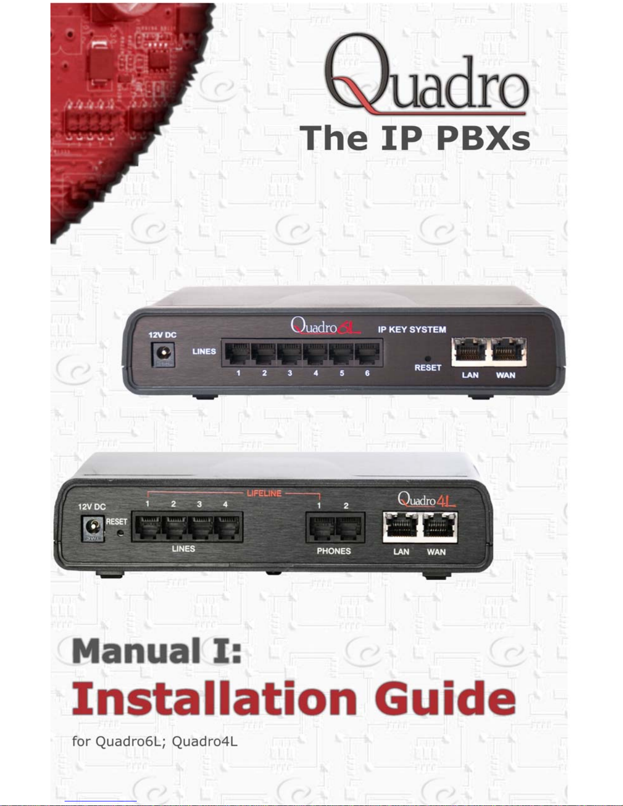

Quadro6L/4L Manual I: Installation Guide
Quadro6L/4L; (SW Version 5.2.x)
Copyright and Trademarks
Copyright © 2003-2012 Epygi Technologies, Ltd. All Rights Reserved. Quadro is a registered trademark of Epygi Technologies, Ltd. Microsoft, Windows, and the Windows logo are registered trademarks of Microsoft Corporation. All other
trademarks and brand names are the property of their respective proprietors.
Limited Warranty
Epygi Technologies, Ltd. (‘Epygi’) warrants to the original end-user purchaser every Quadro to be free from physical defects in material and workmanship under normal use for a period of one (1) year from the date of purchase (proof of purchase required) or two (2) years from the date of purchase (proof of purchase required) for products purchased in the
European Union (EU). If Epygi receives notice of such defects, Epygi will, at its discretion, either repair or replace products that prove to be defective.
This warranty shall not apply to defects caused by (i) failure to follow Epygi’s installation, operation or maintenance instructions; (ii) external power sources such as a power line, telephone line, or connected equipm ent; (iii) products that
have been serviced or modified by a party other than Epygi or an authorized Epygi service center; (iv) products that have
had their original manufacturer’s serial numbers altered, defaced, or deleted; (v) damage due to lightning, fire, flood, or
other acts of God.
In no event shall Epygi’s liability exceed the price paid for the product from direct, indirect, special, incidental, or consequential damages resulting from the use of the product, its accompanying software, or its documentation. Epygi offers no
refunds for its products. Epygi makes no warranty or representation, expressed, implied, or statutory, with respect to its
products or the contents or use of this documentation and all accompanying software, and specifically disclaims its quality, performance, merchantability, or fitness for any particular purpose.
Return Policy
If the product proves to be defective during this warranty period, call Epygi Customer Support at (972) 692-1166 to obtain
a Return Material Authorization (RMA) Number. Registered users also may access Epygi’s Technical Support
(www.epygi.com; ‘Support’) to send their RMA request. For Brazil representatives, call (21) 2518-3161 or contact via Web
(www.saga.com.br). Please have your proof of purchase on hand when contacting us. When returning a product, mark
the Return Authorization Number clearly on the outside of the package and include your original proof of purchase. Return
requests cannot be processed without proof of purchase. Customers are responsible for shipping and handling charges
when shipping to Epygi.
Epygi or its service center will use commercially reasonable efforts to ship a replacement product within ten (10) working
days after receipt of the returned product. Actual delivery times may vary depending on customer location.
Epygi reserves the right to revise or update its products, pricing, software, or documentation without obligation to notify
any individual or entity. Please direct all inquiries to:
Epygi Technologies, Ltd., Two Legacy Town Center, 6900 North Dallas Parkway, Suite 850, Plano, Texas 75024
Representative in Brazil - Saga Sistemas e Computadores SA, Av. Rio Branco, 18 - 8 andar, Rio de Janeiro 20090-001
Notice to Users
This Installation Guide, in whole or in part, may not be reproduced, translated, or reduced to any machine-readable form
without prior written approval.
Epygi provides no warranty with regard to this Installation Guide or other information contained herein and hereby expressly disclaims any implied warranties of merchantability or fitness for any particular p urp os e in rega rd to this ma nua l or
other such information. In no event shall Epygi be liable for any incidental, consequential, or special damages, whether
based on tort, contract, or otherwise, arising out of or in connection with this manual or other information contained herein
or the use thereof.
FCC Statement (Part 15) Class A
• The Epygi Quadro6L/4L has been tested and found to comply with the limits for a class A digital device, pursuant to
Part 15 of the FCC Rules. These limits are designed to provide reasonable protection against harmful interference in
a commercial installation. This equipment generates, uses, and can radiate radio frequency energy and, if not installed and used in accordance with the instructions, may cause harmful interference to radio communications. However, there is no guarantee that interference will not occur in a particular installation. If this equipment does cause
harmful interference to radio or television reception, which is found by turning the equipment off and on, the user is
encouraged to try to correct the interference by one or more of the aforementioned measures.
You are cautioned that any change or modification to the equipment not expressly approved by the manufacturer could
void the user’s authority to operate this device.
Administrative Council for Terminal Attachments (ACTA) Customer Information
This equipment complies with Part 68 of the FCC rules and the requirements adopted by the ACTA. On the back of this
equipment is a label that contains, among other information, a product identifier in the format US:AAAEQ###TXXXX,
made out to HX7OT00BHX70100. If requested, this number must be provided to the telephone company.
Any plug or jack that is used to connect this equipment to the premises wiring and telephone network must comply with
the applicable FCC Part 68 rules and requirements adopted by the ATCA.
The Ringer Equivalence Number is an indicator of the maximum number of devices allowed for connection to a telephone
interface. The termination on an interface may consist of any combination of devices subject only to the requirements that
the sum of the RENs of all the devices does not exceed five. Excessive RENs on a telephone line may result in the devices not ringing in response to an incoming line. The REN for this product is part of the product identifier that has the
format US:AAAEQ## #TXXX, m ade out to HX7OT00BHX70100. The digits represented by ### are the REN without a decimal point (in this case 00B is a REN of 0.0B.)
If the Quadro causes harm to the telephone network, the telephone com pany will notify you in advance that a tempora ry
discontinuance of service may be require d. But if ad vance notice isn’t p rac tical, th e tele phon e com pan y will notif y th e cu stomer as soon as possible. Also, you will be advised of your right to file a complaint with the FCC if you believe it is necessary.

Quadro6L/4L Manual I: Installation Guide
Quadro6L/4L; (SW Version 5.2.x)
The telephone company may make changes in its facilities, equipment, operations or procedures that could affect the operation of the equipment. If this happens, the telephone company will provide advance notice for you to make the necessary modifications to maintain uninterrupted service.
Connection to a party line service is subject to state tariffs. Contact the state public utility commission, public service
commission or the corporation commission for information.
If your home has specially wired alarm equipment connected to the telephone line, ensure the installation of the Quadro
does not disable your alarm equipment. If you have any questions about what will disable alarm equipment, consult your
telephone company or a qualified installer.
Electrical Safety Advisory
To reduce the risk of damaging power surges, we recommend you install an AC surge arrestor in the AC outlet from which
the Quadro is powered.
Industry Canada Statement
This product meets the applicable Industry Canada technical specifications.
Safety Information
Before using the Quadro, please review and ensure the following safety instructions are adhered to:
• To prevent fire or shock hazard, do not expose your Quadro to rain or moisture.
• To avoid electrical shock, do not open the Quadro. Refer servicing to qualified personnel only.
• Never install wiring during a lightning storm.
• Never install telephone jacks in wet locations unless the jack is specified for wet locations.
• Never touch uninsulated telephone wire or terminals unless the telephone line has been disconnected at the net-
work interface.
• Use caution when installing or modifying cable or telephone lines.
• Avoid using your Quadro during an electrical storm.
• Do not use your Quadro or telephone to report a gas leak in the vicinity of the leak.
• An electrical outlet should be as close as possible to the unit and easily accessible.
Emergency Services
The Quadro SIP Service is intended to function as a secondary telephone service. This service is made available through
the Internet and therefore is dependent upon a constant source of electricity and network availability. If a power outage
occurs, the Quadro SIP Service automatically will be disabled. User understands in the event of a power or network outage, the Quadro SIP Service will not support 911 emergency services, and further, such services only will be available via
the user's regular telephone line that is not connected to the Quadro. User further acknowledges that any interruption in
the supply or delivery of electricity or network availability is beyond Epygi's control and Epygi shall have no responsibility
for losses arising from such interruption.

Quadro6L/4L Manual I: Installation Guide
Quadro6L/4L; (SW Version 5.2.x)
Table of Contents
Manual I: Installation Guide
About This Installation Guide........................................................6
Requirements.............................................................................7
Hardware Overview.....................................................................8
The Connectors Panel of Quadro6L/4L......................................................8
Quadro6L/4L’s Front Panel LEDs..............................................................9
Step 1: Installing the Quadro ..................................................... 11
Networking Overview...........................................................................11
LAN/WAN Connection Options ...............................................................12
Connecting the Hardware .....................................................................16
Step 2: Configuring the Quadro .................................................. 20
Step 2.1: Logging into Quadro ..............................................................20
Step 2.2: System Configuration Wizard..................................................21
System Configuration.....................................................................................21
DHCP Settings for the LAN Interface.................................................................22
Regional Settings...........................................................................................22
Emergency and PSTN Access Code Settings .......................................................23
Finishing the System Configuration Wizard ........................................................24
Step 2.3: Internet Configuration Wizard .................................................26
Uplink Configuration.......................................................................................27
WAN IP Configurat ion.....................................................................................28
PPP/PPTP Configuration...................................................................................29
WAN Interface Configuration ...........................................................................30
DNS Settings ................................................................................................30
Finishing the Internet Configuration Wizard........................................................31
Step 2-A: Using IP Lines............................................................32
Supported SIP Phones.......................................................................... 35
Tested SIP Phones...............................................................................35
Step 2-B: Using Key System Emulation........................................ 37
Using SLA Lines for SIP Calls ................................................................38
How to disable the Key System Emulation .............................................. 40
Step 2-C: Using Receptionist...................................................... 41
Step 3: Registering on Epygi’s Technical Support...........................42
Step 4: Making/Receiving Calls...................................................43
Using the Default SIP Addresses............................................................43
Appendix: Changing the Admin Password.....................................45
Appendix: Configuring NAT Traversal........................................... 47
Appendix: Registering on Epygi’s SIP Server................................. 50
Appendix: Checking the Connections ........................................... 55

Quadro6L/4L Manual I: Installation Guide
Manual II: see Administrator's Guide
This guide describes in detail the menus available for administrators only. Furthermore, it includes all the system’s default values at a glance.
Manual III: see Extension User's Guide
This guide describes in detail the menus av ailable for extension users. F urthermore, it includes all the call codes at a glance.
Quadro6L/4L; (SW Version 5.2.x)

Quadro6L/4L Manual I: Installation Guide About This Installation Guide
About This Installation Guide
This Installation Guide explains the installation of the Quadro IP PBXs of Quadro6L and
Quadro4L series.
• Quadro6L offers 6 phone lines (FXO), 1 Ethernet LAN port and 1 Ethernet WAN
port as external interfaces.
• Quadro4L offers 4 phone lines (FXO), 2 phone extensions (FXS), 1 Ethernet LAN
port and 1 Ethernet WAN port as external interfaces.
This Installation Guide gives step-by-step instructions to provision the Quadro and configure the phone extensions with the Epygi SIP Server. After successfully configuring the
Quadro, a user will be able to make SIP phone calls to remote Quadro devices, make local
calls to the PSTN and access the Internet from devices connected to the LAN.
This Installation Guide neither describes the PBX, Auto Attendant, Call Relay, and Voice
Mail features of the Quadro nor does it provide advanced firewall and VPN configuration information. For these features, refer to the Administrator's and Extension User's Guides.
Step 1: Installing the Quadro
explains the connection of cables and devices to the Qua-
dro.
XXStep 2: Configuring the Quadro describes the configuration steps necessary to integrate
the Quadro into your network environment.
XXStep 2-A: Using IP Lines explains how to configure IP lines on the Quadro IP PBX and t o
connect IP phones to become functional in the Quadro’s LAN.
Step 2-B: Using Key System Emulation
explains how to configure SLA lines.
Step 2-C: Using Receptionist
refers to the document describing Receptionist’s configura-
tion on the Quadro.
Step 3: Registering on Epygi’s Technical Support
shows you how to access the Epygi
Technical Support Center and the Epygi SIP Server.
Step 4: Making/Receiving Calls
X explains how to enable the Quadro’s various telephony
features.
Appendix: Changing the Admin Password
explains how to change the default administra-
tor password.
Appendix: Configuring NAT Traversal
explains configuration of the Quadro if it is placed
behind a NAT enabled router.
Appendix: Registering on Epygi’s SIP Server
X explains how to register on Epygi's powerful
SIP server.
Appendix: Checking the Connections
gives hints on solving common problems.
Quadro6L/4L; (SW Version 5.2.x) 6

Quadro6L/4L Manual I: Installation Guide Requirements
Requirements
• One 120/240 VAC power outlet in close proximity to the Quadro.
• One RJ45 Ethernet 10/100 broadband Internet connection.
• At least one RJ11 telephone connection is recommended to connect the Quadro to
the PSTN network.
• At least one IP phone with an RJ45 connector connected to the Quadro WAN port
directly or through a hub or switch.
• One CAT 5 Ethernet cable with an RJ45 connector to connect to the Quadro LA N
port.
• One PC with a 10/100 Mbps Ethernet card or adapter installed.
• TCP/IP network protocol installed on each PC.
• For optimal results, Internet Explorer 5.5 or higher, or Netscape Navigator 4.7 or
higher are recommended.
Please Note: The Quadro6L/4L is shipped with one RJ11 cable and one straight RJ45
CAT 5 cable. If the LAN connector of the Quadro connects to a hub or switch, a crossover
cable may be required.
Quadro6L/4L; (SW Version 5.2.x) 7
Quadro6L/4L Manual I: Installation Guide Hardware Overview
Hardware Overview
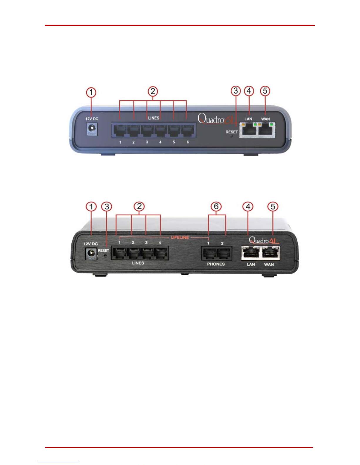
The Connectors Panel of Quadro6L/4L
The illustration below includes the connector’s panel of Quadro6L model.
Fig. l- 1: Connectors Panels of Quadro6L IP PBX
The illustration below includes the connector’s panel of Quadro4L model.
Fig. l- 2: Connectors Panels of Quadro4L IP PBX
1. Power supply socket. Use only the power adapter delivered with the Quadro.
2. LINES sockets to connect the Quadro to the PSTN network using standard ana-
log phone service. These are FXO (Foreign Exchange Office) analog ports.
3. The Reset button may be used in two ways: (1) to initiate a norm al reset or (2) to
carry out a factory reset. A normal reset is executed by pressing the Reset button with a paper clip for an instant.
Pressing the reset button and holding it down for seven seconds or more will
execute a factory reset. This will restore the factory defaults and clear all settings
including the IP address and the administration password you entered.
Please Note: A Factor y Reset forces the default LAN IP address of 172.30.0.1
and default admin password of 19.
4. RJ45 socket to attach to the Local Area Network (LAN) via an Ethernet CAT 5
cable. If a PC is connected directly to this socket, a straight cable is used. If an
Ethernet hub, router or switch is used; a crossover cable may be required. This
port may also be used to connect IP phones to the Quadro (optional). In this
case, it is recommended to use a hub or a switch to connect the PC along with IP
phones to the Quadro’s LAN port.
Quadro6L/4L; (SW Version 5.2.x) 8
Quadro6L/4L Manual I: Installation Guide Hardware Overview
5. RJ45 socket to attach the Internet Uplink (WAN) via an Ethernet CAT 5 cable.
This port may also be used to connect IP phones to the Quadro. Th e default con figuration settings assume that IP phones are attached to this, rather than the
LAN port.
6. PHONE sockets with RJ11 connectors enable connectivity of regular analog tele-
phones. These are FXS (Foreign Exchange Station) analog ports.
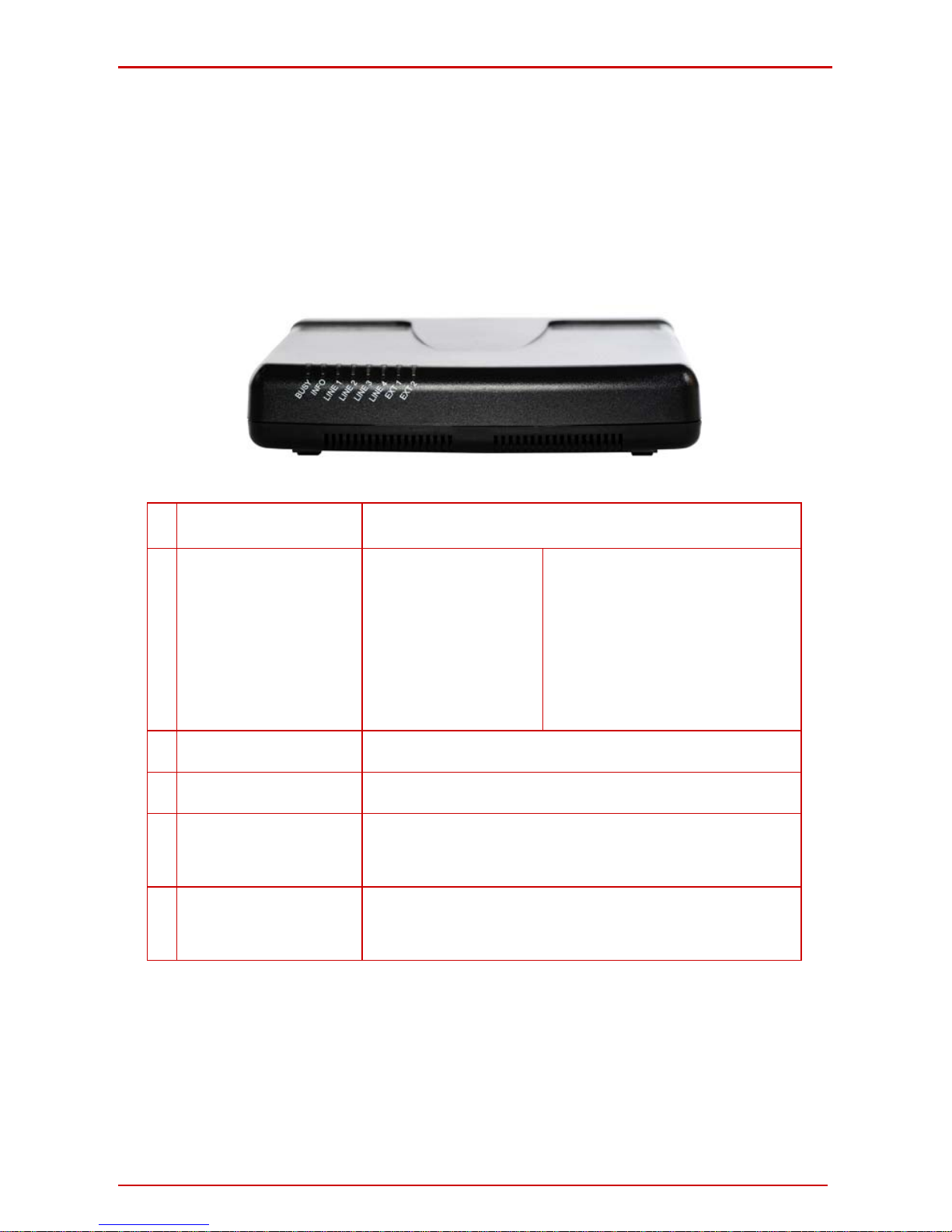
Quadro6L/4L’s Front Panel LEDs
Fig. l- 3: Quadro4L's Front Panel LEDs
1
BUSY, green
Status of CPU
off: No power
on or blinking: Normal activity
2
INFO/FAULT,
yellow/red/green
System information
on (yellow):
device is booting
on (red):
error or system is booting
on (green):
system is operational
blinking (yellow/green):
event occurred, details specified in
the System Event section of the Management interface
blinking (red/green):
system unusable
blinking (red/yellow):
emergency firmware is needed
blinking (red/green/red/yellow):
firmware update
3
For Quadro 6L- Green
LED for FXO Line 1– 6
on or blinking: line in use
off: line not in use
4
For Qudaro4L- Green LED
for FXO Line 1 – 4
on or blinking: line in use
off: line not in use
5
EXT 1, green
Status of the FXO LINE
3(available only for
Quadro4L)
on or blinking: line in use
off: line not in use
6
EXT 2, green
Status of the FXO LINE 4
(available only for
Quadro4L)
on or blinking: line in use
off: line not in use
LED Indication during a firmware update
A firmware update is indicated by the yellow/red/green Info/Fault LED. It will blink
red/green for about five minutes while the firmware is updated. The Quadro will then reboot automatically showing the boot LED sequence.
LED Indication during a boot sequence
A boot sequence is indicated as follows: The yellow/red/green Info/Fault LED will glow red
for a few seconds, then turn to yellow for another four or five minutes while the green Busy
LED is blinking. Once the Info/Fault LED is green, the boot sequence has been completed
Quadro6L/4L; (SW Version 5.2.x) 9

Quadro6L/4L Manual I: Installation Guide Hardware Overview
successfully.
LED indication during uploading an emergency firmware
The yellow/red/green Info/Fault LED will stop blinking alternately red/yellow and start blinking red/green/red/yellow. This shows that Quadro has accepted the emergency firmware
and is loading it. After a few seconds, Quadro will boot, showing the boot LED sequence.
Quadro6L/4L; (SW Version 5.2.x) 10

Quadro6L/4L Manual I: Installation Guide Step 1: Installing the Quadro
Step 1: Installing the Quadro
Networking Overview
To establish a connection between the Internet and your local area net work (LAN), an access router is needed. The Quadro6L/4L may serve, among other functions, as an access
router, and will perform the task of connecting your LAN, or a group of one or more PCs, to
the wide area network (WAN) or the Internet. The Quadro will process and regulate the data traffic between these two networks. The Quadro6L/4L has one LAN port that can connect to Ethernet hubs and switches on the LAN, allowing additional devices to be connected to the network.
The Quadro is a device with two sides: one side connects to your LAN, and the ot her side
connects to the Internet, or the WAN. Quadro’s firewall and Network Address Translation
(NAT) functionality protects your LAN from being seen from the Internet side making the
LAN private and secure.
The Ethernet WAN port transmits up to 10 Mbps, and the LAN port transmits at 10 Mbps or
100 Mbps.
Every device within an IP network requires a unique IP address to identify itself. Since the
Quadro connects to both the LAN and the WAN, it has to be part of both networks, and
must have two IP addresses: one for the WAN side and one for the LAN side. The Quadro’s integrated firewall/NAT functionality will hide the LAN IP address from the WAN (Internet) side.
There are two ways of assigning an IP address: statically or dynamically.
A Static IP address is a fixed, manually assigned IP address that remains valid until
changed. If you plan to use the Quadro as your Internet access router, contact your Internet
Service Provider (ISP) to find out if a static IP address is assigned to your account. If so,
you will need this static IP address when configuring the Quadro device.
A dynamic IP address is a temporary address that is automatically assigned by your ISP
and will change periodically. If your ISP offers a dynamic IP address, the Quadro will act as
a DHCP client and will receive a new IP address from the ISP’s DHCP server or PPPoE
feature.
Please Note: A DHCP client is a piece of software that requests an IP address from a
DHCP server. A DHCP server assigns on request a unique IP address to a device. The
Quadro, like many routers, acts as a DHCP client on its WAN interface and as a DHCP
server on its LAN interface.
The Quadro must be visible to the Internet to be able to receive and send VoIP calls. When
the Quadro is placed in a private network, typically behind existing routers, it will by default
attempt to pass through the NAT of this router with its STUN (Simple Traversal of UDP over
NAT) feature. STUN will work without user configuration with the majority of basic routers.
In some scenarios, port forwarding on the router is required to make the Quadro accessible
to other Quadro devices and the Epygi SIP Server on the Internet. Another configuration
option is to use the Quadro as the Internet access router, connected directl y to the WAN,
eliminating the traverse to the local NAT firewall.
Quadro6L/4L; (SW Version 5.2.x) 11
Quadro6L/4L Manual I: Installation Guide Step 1: Installing the Quadro
LAN/WAN Connection Options
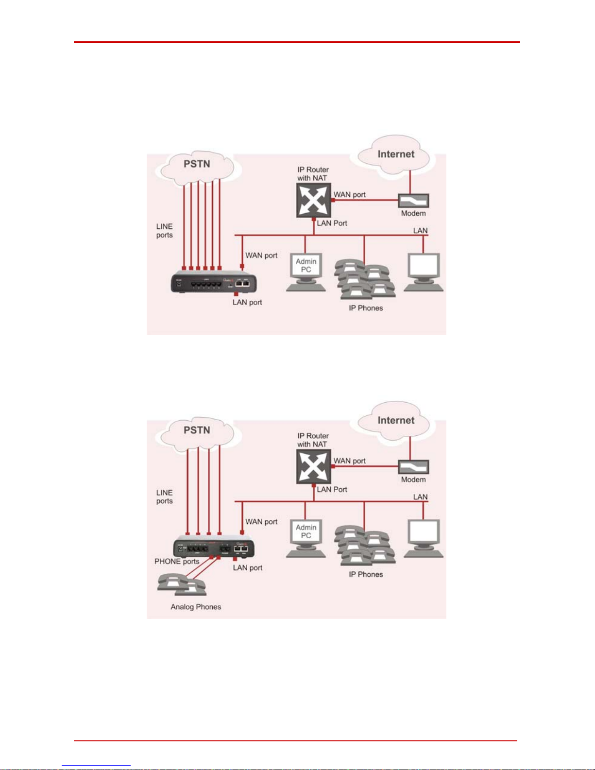
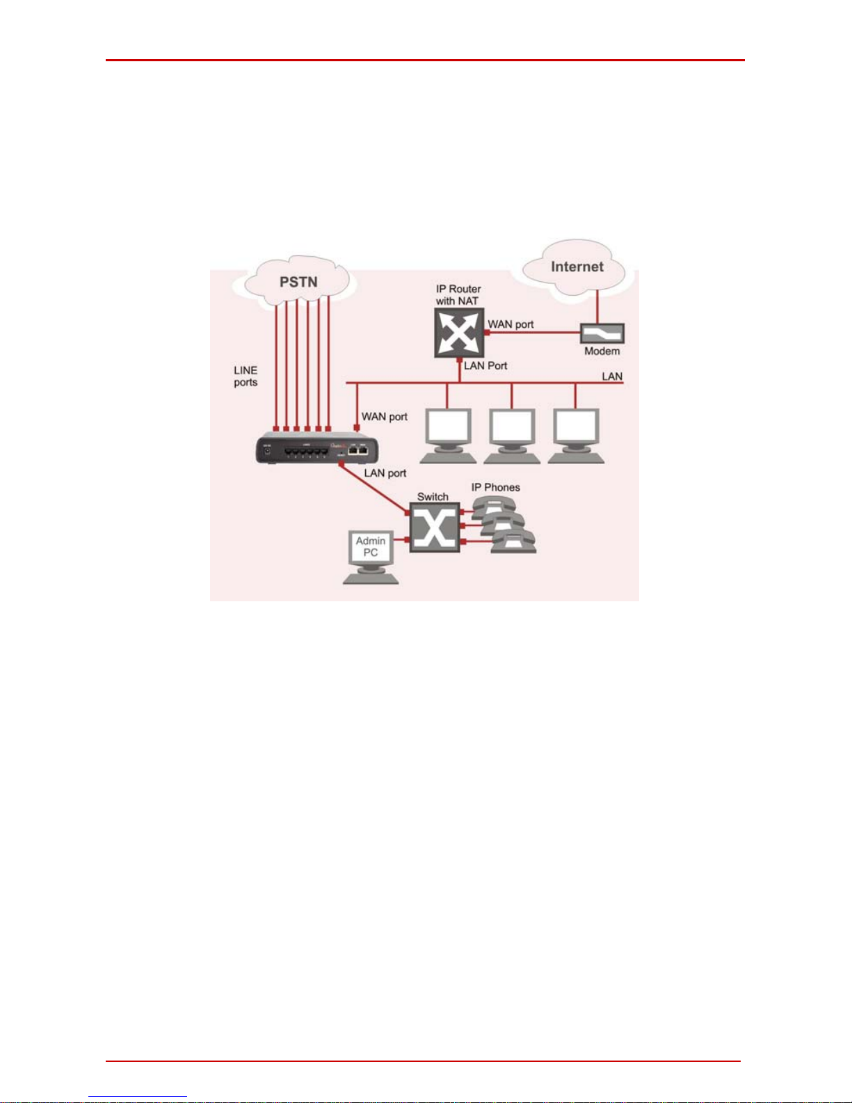
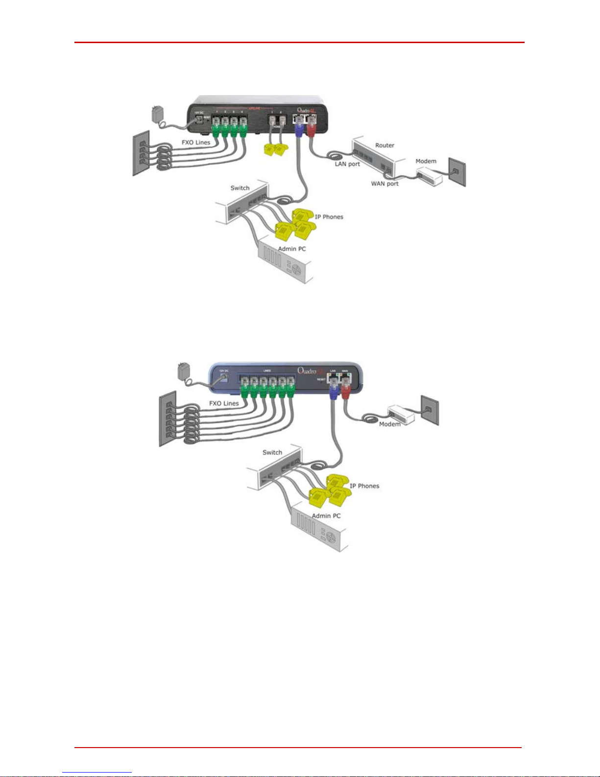
• A Quadro6L with an Ethernet WAN port be hind a rou ter, which is connected
to a cable or xDSL modem. IP phones are pl aced on the WAN side of the
Quadro6L.
Fig. l- 4: Configuration: Quadro6L behind a router with IP phones on WAN
• A Quadro4L with an Ethernet WAN port be hind a rou ter, which is connected
to a cable or xDSL modem. IP phones are pl aced on the WAN side of the
Quadro4L.
Fig. l- 5: Configuration: Quadro4L behind a router with IP phones on WAN
In this and the following configuration (Fig. I -4, Fig. I -5, Fig. I -6 and Fig. I -7), the IP router
typically acts as a DHCP server for the LAN and assigns the IP addresses to the PCs and
other devices. The Quadro can be connected through its WAN port directly to one of the
router's LAN ports and will get an IP address from the router. By default, the Quadro act s
as a DHCP client on the WAN port. The IP phones are placed on the WAN side of the
Quadro6L, connected to the company LAN.
The Admin PC can be connected to the Quadro WAN or LAN port to access the Web Man-
Quadro6L/4L; (SW Version 5.2.x) 12
Quadro6L/4L Manual I: Installation Guide Step 1: Installing the Quadro
agement of the Quadro.
Please Note: Since Quadro uses STUN b y default, it will work with most basic rou-
ters without any further configuration.
• A Quadro6L with an Ethernet WAN port be hind a rou ter, which is connected
to a cable or xDSL modem. I P phones are placed on the LAN side of the
Quadro6L.
Fig. l- 6: Configuration: Quadro6L behind a router with IP phones on LAN
• A Quadro4L with an Ethernet WAN port be hind a rou ter, which is connected
to a cable or xDSL modem. I P phones are placed on the LAN side of the
Quadro4L.
Quadro6L/4L; (SW Version 5.2.x) 13
Quadro6L/4L Manual I: Installation Guide Step 1: Installing the Quadro
Fig. l- 7: Configuration: Quadro4L behind a router with IP phones on LAN
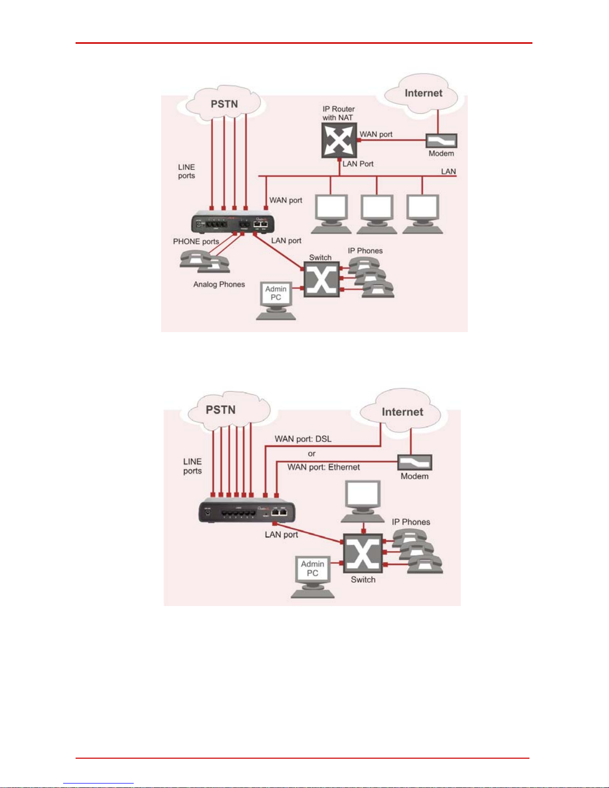
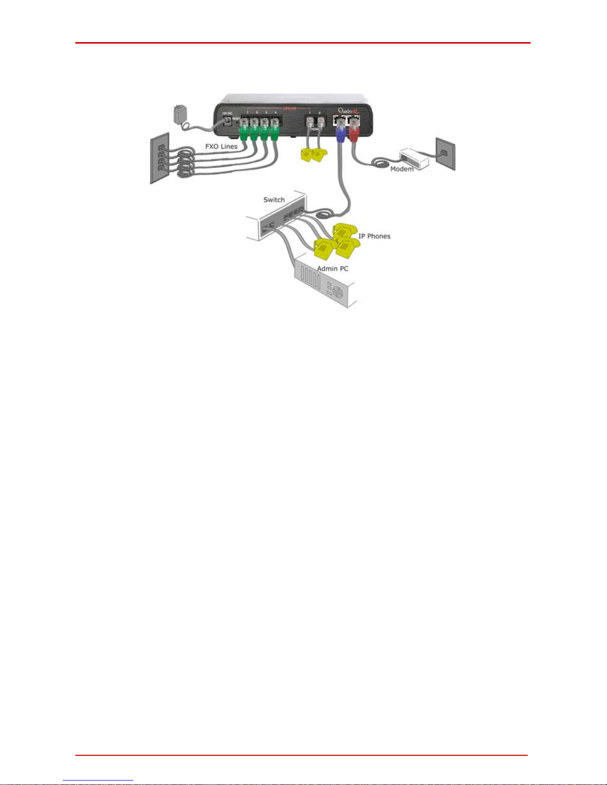
• A Quadro6L used as an Internet Access Rou ter, connected directly to the
Internet.
Fig. l- 8: Configuration: Quadro6L used as Internet Access Router
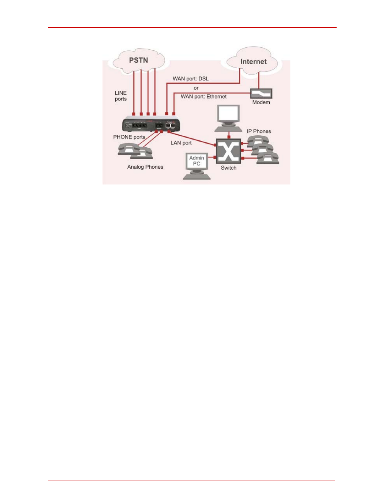
• A Quadro4L used as an Internet Access Rou ter, connected directly to the
Internet.
Quadro6L/4L; (SW Version 5.2.x) 14
Quadro6L/4L Manual I: Installation Guide Step 1: Installing the Quadro
Fig. l- 9: Configuration: Quadro4L used as Internet Access Router
Please Note: The Admin PC is connected to the Quadro’s LAN p ort through a switch/hub
to access the Web Management of the Quadro (Fig. I -6, Fig. I -7, Fig. I -8 and Fig. I -9). It
is recommended to have Admin PC acting as a DHCP client and obtaining IP address from
the Quadro.
Quadro6L/4L; (SW Version 5.2.x) 15
Quadro6L/4L Manual I: Installation Guide Step 1: Installing the Quadro
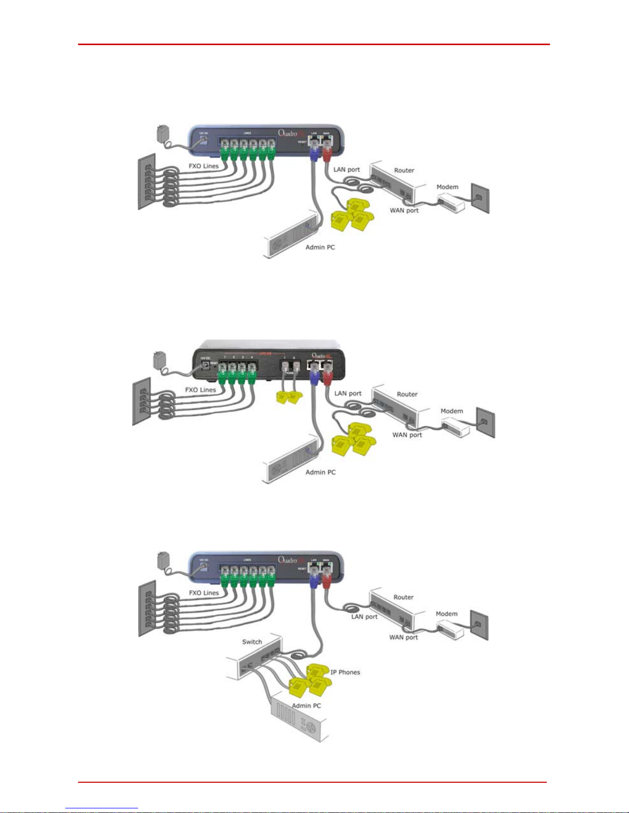
Connecting the Hardware
• Quadro6L behind a router with IP phones c onnected to WAN
Fig. l- 10: Installation: Quadro6L behind a router with IP phones on WAN
• Quadro4L behind a router with IP phones c onnected to WAN
Fig. l- 11: Installation: Quadro4L behind a router with IP phones on WAN
• Quadro6L behind a router with IP phones c onnected to LAN
Fig. l- 12: Installation: Quadro6L behind a router with IP phones on LAN
Quadro6L/4L; (SW Version 5.2.x) 16
Quadro6L/4L Manual I: Installation Guide Step 1: Installing the Quadro
• Quadro4L behind a router with IP phones c onnected to LAN
Fig. l- 13: Installation: Quadro4L behind a router with IP phones on LAN
• Quadro6L used as Internet access router
Fig. l- 14: Installation: Quadro6L used as an Internet Access Router
Quadro6L/4L; (SW Version 5.2.x) 17
Quadro6L/4L Manual I: Installation Guide Step 1: Installing the Quadro
• Quadro4L used as Internet access router
Fig. l- 15: Installation: Quadro4L used as an Internet Access Router
• Verify the product package contents are complete. Refer to the contents sheet in-
cluded in the packaging to determine if all the items were shipped in the box.
• Before you connect the hardware, make sure that all devices are powered off.
• Connect at least one of Quadro's LINE (FXO) ports to the telephone service from the
PSTN. The Quadro6L offers connectivity of six lines and the Quadro4L offers
connectivity of four lines.
Please Note: If your Internet connection is a DSL modem, you m ay ne ed to use a mi-
cro filter between the FXO LINE port and the phone line. Micro filters are typically provided by your ISP but are also available at most computer stores. If a micro filter is already installed, simply connect the RJ11 from the existing phone to the Quadro6L port
leaving the micro filter connection as is.
• Connect the Ethernet port on your PC via a straight CAT 5 cable with an RJ45 con-
nector to the LAN socket of the Quadro. If a hub or switch is connected between the
Quadro and your PC, use a crossover cable from the LAN interface of the Quadro to
the hub/switch.
• Connect at least one SIP phone to the Quadro. You will need an intermediate
hub/switch. Use a crossover cable to connect the hub/switch to the Quadro’s LAN or
WAN socket. Plug your SIP phones to the hub/switch with a straight CAT 5 cable with
an RJ45 connector. The same hub/switch can also be used to connect PCs to the Quadro.
• Connect the WAN port of the Quadro to the Internet service via a cable or DSL mo-
dem.
• Power up the DSL or Cable modem first.
• Connect the power adapter to the POWER port on the Quadro’s rear panel an d plug
the power adapter into a power outlet. Only use the original Quadro power adapter
and plug it into a power strip with surge protection or to a UPS if available.
The red LED (Fault) will glow for several seconds followed by the yellow LED (Info),
which will glow for several minutes. When Info LED is off, the Quadro is operational.
• Power up any hub or switch followed by any PC and other devices on the LAN side.
• Check the LEDs: The green Busy LED must glow continuously. The green LAN and
WAN LEDs will blink when cables are connected to these ports and all devices are
powered up. If the green LAN and WAN LEDs do not blink, verify cabling and ensure
Quadro6L/4L; (SW Version 5.2.x) 18
 Loading...