


MODEL:
CTV-63N11 TXT
CTV-72D11 TXT
CTV-72SF65 TXT
CTV-72SF50 TXT
SERVICE MANUAL
Brown goods
TV SETS 25", 29" 5P19 chassis

Note
-2-
Note----------------------------------------------------------------Technical specification-------------------------------------------Chassis Block Diagram-------------------------------------------IC Block Diagram --------------------------------------------------Transistor mark ---------------------------------------------------PCB Top/Bottom layer --------------------------------------------Service Adjustments ----------------------------------------------Control Location ----------------------------------------------------
Input and Output Terminal-----------------------------------------27-30
Operation Instructions--------------------------------------------Circuit Diagram-----------------------------------------------------
2
3-6
7
8-10
11
12-13
14-25
26
31-43
44

Technical Specification
-3-
SUPPLY VOLTAGE : AC 90-260V 50/60Hz
1.SYSTEM PAL / SECAM / NTSC
2.CHANNELS RECEIVED 0~199
3.SCANNING HORIZONTAL 15625Hz
VERTICAL 50Hz
4.VISION INTERMEDIATE FREQUENCY 38.9 MHz
5.SOUND INTERMEDIATE FREQUENCY 33.4 MHz B/G
6.INTER-CARRIER FREQUENCY 5.5/6.0/6.5/4.5 MHz
7.CHROMA IF FREQUENCY PAL 34.47 MHz
8.ANTENNA INPUT IMPEDANCE 75 OHM
9.CRT 29 RF/SLIM
10.VIDEO SENSITIVITY AT 30dB S/N (ACCORDING TO CCEE)
VHF 48 48 dBuV
UHF 51 51 dBuV
(50% WHITE, 1KHz-50Hz, UNWEIGHTED, SC TRAPPED)
11.FM SOUND SENSITIVITY AT 30dB S/N 25 38 dBuV
12.SYNCHRONIZING SENSITIVITY 22 26 dBuV
13.AGC CHARACTERISTIC 65 60 dB
14.SELECTIVITY 35 30 dB
15.I.F. REJECTION 50 45 dB
16.IMAGE REJECTION 50 45 dB
17.AUDIO OUTPUT POWER 1khz 6 or 10 W
(10% THD)
18.MAXIMUM OUTPUT POWER 12 W
19.THD SUPPLYING 1KHz 500mW 0.3 0.5 %
TO SPKR
20.MINIMUM VOLUME HUM 5 10 mVrms
()
”
<
NORMAL LIMIT UNIT
21.MAX. BRIGHTNESS 100% WHITE, 80 cd/m
CONTROLS MAX
22.H SYNC. PULL IN 400 -400 Hz
23.V.SYNC. PULL IN +5 -6 45-64 Hz
24.OVERSCAN 94 88-96 %
25.COLOUR SENSITIVITY 35 dBuV
26.LINEARITY PAL HORIZONTAL 7/8 10/12 %
VERTICAL 3/5 8/15 %
27.RESOLUTION HORIZONTAL 330 300 LINES
VERTICAL 450 LINES
28.PICTURE POSITION HORIZONTAL -5 +5 -5 +5 mm
VERTICAL -4 +4 -6 +6 mm
29.CONVERGENCE C 0.4 mm
T, B, R, L 1.6 mm
TR,TL,BR,BL 2.0 mm
2
,
,
,
100
+700 -600
26
500
0.3
1.0
1.6
,
Technical Specification
-4-
30.WHITE BALANCE(9300 K, LOW BRI <10cd/m , HI BRI >80cd/m )
(SET BURST OFF OF PATTERN GENERATOR OR SET COLOUR SAT. TO MIN
MEASURED BY MINOLTA CA-100)
0.260 x:0.288 0.015
0.302 y:0.298 0.015
31.HIGH VOLTAGE (decided by CRT Spec. ) 29 31 KV
32.X-RAY RADIATION 0.2 0.2 MR/HR
33.REMOTE CONTROL RECEPTION 6 5 m
(30 DEGREES)
34.VIDEO INPUT (AV ) 1 0.9-1.1 Vp-p
35.AUDIO OUTPUT(AV-OUT) 0.55 0.5(-0.1+0.3)Vrms
36.COLOUR LEVEL 90 80 %
(RED CATHODE, STANDARD PICTURE MODE, COLOUR BAR TEST PATTERN)
37.POWER CONSUMPTION 90 120 W
38.STANDBY POWER CONSUMPTION 2 3 W
(AT 220V AC)
39.FREQUENCY RESPONSE
(1 KHz = 0dB, REF : 1.0V) 100Hz +1.5~+8.9 +3, -6 dB (TBC)
10KHz -0.9~-20 +3, -6 dB
o22
40.DIELECTRIC STRENGTH TEST -- 6 mArms
(3 KV Vrms 2SEC)
41.OPERATING WORKING VOLTAGE RANGE 82-264 84-260V
42.AFC PULL IN RANGE +2.2, -1.75 +1 -0.75 MHz
43.TV/AV CROSSTALK (REF : 2W) 40 dB
(WEIGHTED DIN NOISE)
44.PICTURE MODE
STANDARD: Half Contrast, Half Bright.
SOFT: 1/3CONTRAST, 1/3 Bright.
RICH: MAX Contrast, Half Bright.
USER: PERSONAL PREFERENCE.
45
TL T TR
LC R
BL B BR
320mm
240mm
TEST CONDITIONS :
TEMPERATURE : 23 C 5 C
HUMIDITY : 50% +/-20
OPERATING VOLTAGE : AC220 50Hz Vrms 5V
PICTURE MODULATION DEPTH : 87.5%
SOUND MODULATION DEPTH : 100%
PICTURE TO SOUND RATIO : 10dB
VIDEO REFERENCE OUTPUT AT RED GUN : 25 Vp-p
AUDIO REFERENCE OUTPUT AT SPEAKER:1W
ANTENNA INPUT IMPEDANCE : 75 OHM UNBALANCED
WHITE BALANCE CHECKED BY MINOLTA CA-100
oo

OPERATION ON AC90-260V 50/60Hz MAIN SUPPLY
SYSTEM: PAL SECAM BG/DK/I NTSC-M
200 PROGRAMMES MEMORY
FULL ON SCREEN DISPLAY
BLUE SCREEN DISPLAY
180 MINUTES SLEEP TIMER
FULL AUTO PROGRAM
REAR YUV L+R/AV IN /AV OUT OR FULL SCART/HALF SCART
SIDE AV IN/S-VHS IN
BLACK LEVEL STRETCH
TIME SETTING
CHILD LOCK
FOUR PICTURE MODE: STANDARD RICH SOFT USER
TV SYSTEM : PAL SECAM BG/DK/I NTSC-M
RECIVE FRENQUENCY COVERAGE: 45.15MHz -863.25MHz
INTERMEDIATE FREQUENCIES
PICTURE I.F.: 38.9MHz
CHROMA SUBCARRIER: 34.47MHz/35.32MHz
MONO SOUND I.F.: FM33.4MHz/32.4MHz/32.9MHz/34.4MHz
4 ANRENNA IMPEDANCE: 75 OHM BALANCED
5 AV IN: 1 AV IN;YUV(YCbCr) IN SCART IN
6 AV IN SPECIFICATION:
Y:1.0 0.2Vp-p 75 OHM
C:0.3Vp-p 75 OHM
VIDEO IN 1.0 0.2Vp-p 75 OHM
AUDIO IN APPROX 500mv
7 TUNING SYSTEM: FREQUENCY SYNTHESISED WITH 200
PROGRAMMES MEMORY
8 POWER SOURCE: AC90-260V 50/60Hz
9 LED INDICATORS: POWER ON OR STANDBY
10 OSD LANGUAGE: ENGLISH
11 CONTROLS ON TV SET
(A) FRONT PANEL
- MAIN POWER SWITCH
- PROG+/- SOFT TOUCH
- VOL+/- SOFT TOUCH
- MENU SOFT TOUCH
- TV/AV SOFT TOUCH
-OPEN /CLOSE SOFT TOUCH
-STOP SOFT TOUCH
- PLAY SOFT TOUCH
(B)BACK PANEL
- YUV L+R/AV IN /AV OUT OR FULL SCART/HALF SCART
FEATURES:
GENERAL SPECIFICATION:
?
?
?
?
?
?
?
?
?
?
?
?
?
:
:
、
、
、
、
、 ;
、
、
、
、
、
、
1
2
3
Technical Specification
-5-

12 ANTENNA INPUT: 75 OHM AERIAL JACK
13 AV INPUT: RCA SOCKET
14 HAND SET POWER SUPPLY: BATTERY 3V(UM-3/R6/AAA) 2
15 HAND SET WEIGHT: 100g(APPROX.)
16 AUDIO OUTPUT: >6W or >10W (1KHz 0.5V , INPUT 10% THD)
17 SPEAKER: 8 OHM 15W/ 6OHM 15W
18 POWER CONSUMPTION: 120W
19 COLOUR PICTURE TUBE: RF/ SLIM
20 PACKING: 1SET PER 1 GIFTBOX
21 ACCESSORIES: OWNER S MANUAL IN ENGLISH WITH BRAND
NAME AND WITH MODE NO. REMOTE HANDSET
、
、
、
、
、
、
、<
、
、
、'
、
≦
、0℃
、
、
22 DIELECTRIC STRENGTH TEST
(3KV rms 60 SEC) 6mA rms
23 OPERATING TEMPERATURE RANGE: BEST 10 TO 4
24 AC LINE CORD PLUG: VDE TYPE OR SUBJECT TO CUSTOMER REQUEST
25 SAFETY : IEC-60065
Technical Specification
-6-
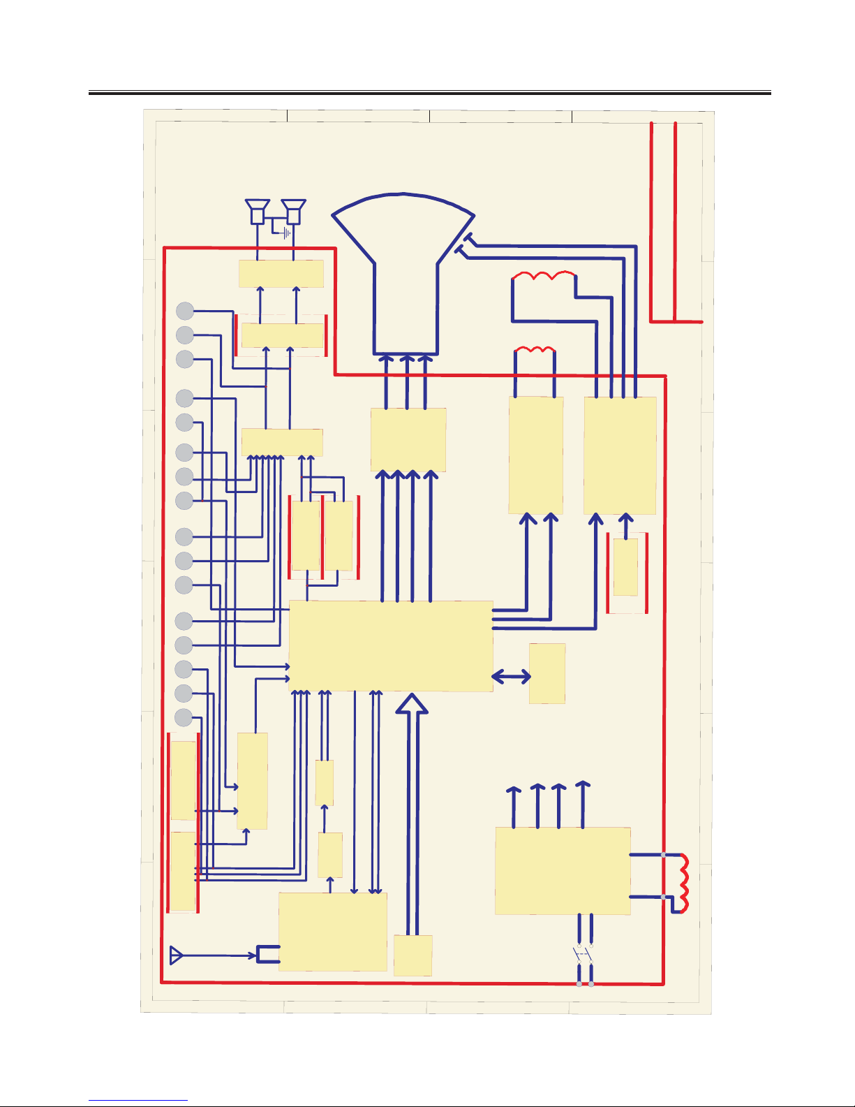
Chassis Block Diagram
-7-
1
2
3
4
56
A
B
C
D
6
5
4
3
2
1
D
C
B
A
TDA9384--India
SCART 1
SCART 2
Y
RGB
UV
Vin
Vin
REAR AV SIDE AV S-VHS
CinAV in
ANTENNA
TUNER IF AMP
SAW101
IF
IF
NICAM-TDA9874
MTS-TDA9850
AV-SW HEF 4052
L
R
AV OUT
V
LR
YCVLRR
L
V
LR
AMP-TDA9842/9843
L
R
TONE CONTROL
AUDIO
R
G
B
8V
24C08
W6556A
V-AMP TDA4863AJ
H-DRIVE
SPL
SPR
CRT BOARD
29" CRT
V--DY
H--DY
R OUT
G OUT
B OUT
SW
90V-260V
DEG COIL
POWER SUPPLY
SCL
SDA
PHILIPS UOC2
+135V FOR B+
+43V FOR H-drive
+12V FOR MAIN
+20V FOR AMP
5P19
side V
CVBS OUT
SLIM PART
TDA9363--AP\ME
Key Control
TDA9859
XULI
Tuner AGC
Video--SW HEF 4052
H-out
Va-out
Vb-out
SLIM OR RF
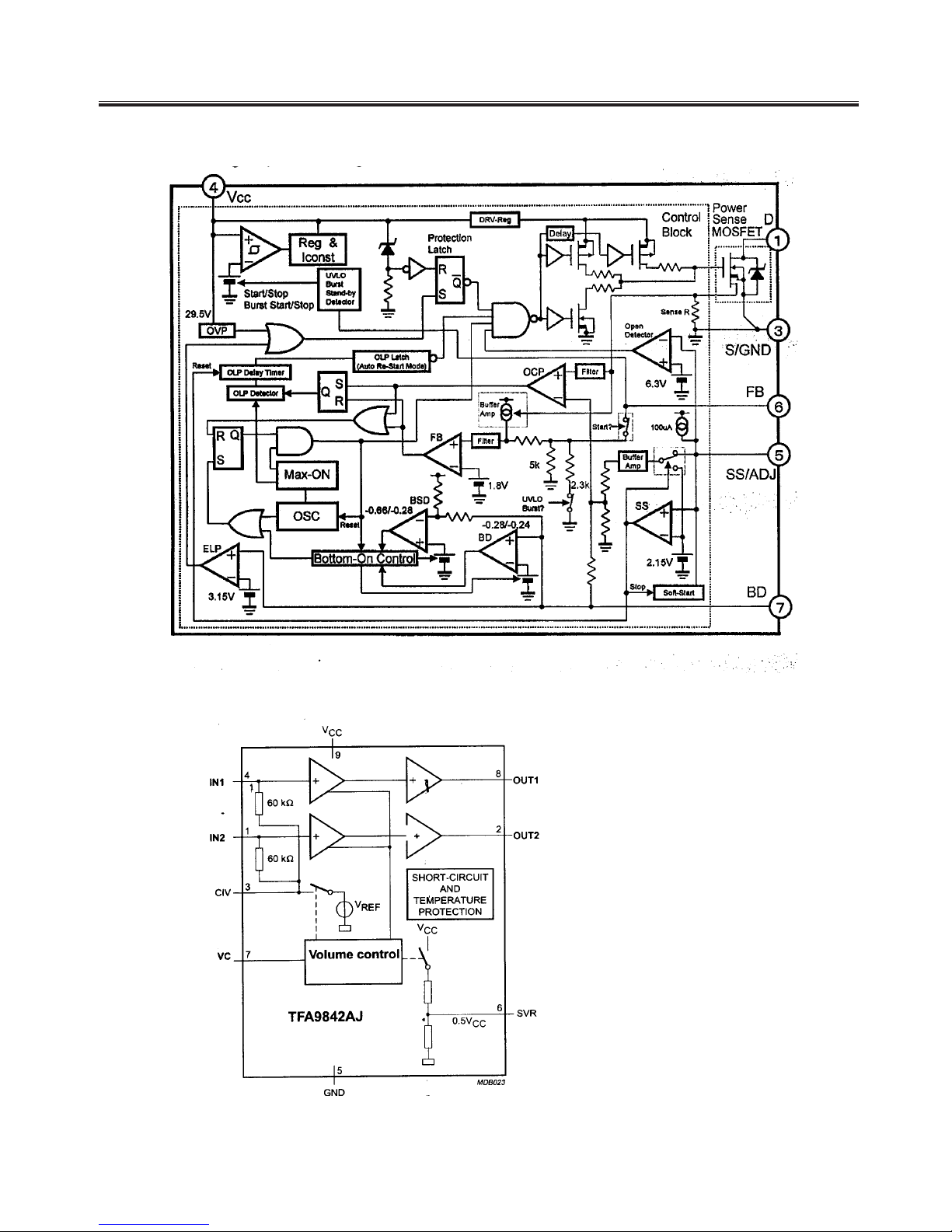
IC Block Diagram
-8-
IC601(POWER SUPPLY)STR-W6556A
IC760(2CHANNEL AUDIO AMPLIFIER WITH VOLUME CONTROL)TFA19842AJ

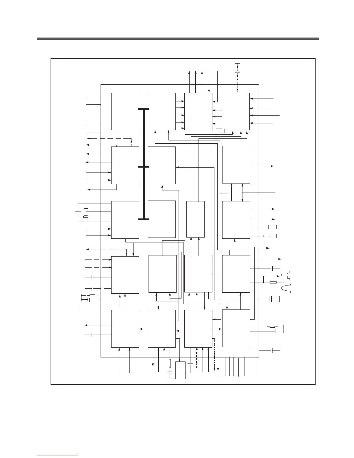
IC Block Diagram
-9-
IC740(UNIVERSALHI-FI AUDIO PROCESSOR FOR TV)TDA9859
IC Block Diagram
-10-
SOUND
TRAP
TUNERAGC
+8V
HOUT V-DRIVE
RO
GO
BO
BCLIN
BLKIN
CVBS3/Y
SIFIN
Fig. 1 Block diagram
C
SDA
SCL
VISION IF
PLL DEMOD.
AGC/AFC
VIDEO AMP.
VIDEO SWITCH
VIDEO IDENT.
VIDEO FILTERS
PAL/SECAM/NTSC
DECODER
DEEMPHASIS
AUDIO SWITCH
AVL
VOLUME CONTROL
BASE-BAND
DELAY LINE
H/V SYNC SEP.
H-OSC. + PLL
H-DRIVE
2
nd
LOOP
H-SHIFT
V-DRIVE +
CONTR/BRIGHTN
OSD/TEXT INSERT
CCC
WHITE-P. ADJ.
80C51 CPU
I
2
C-BUS
TRANSCEIVER
ROM/RAM
TELETEXT
ACQUISITION
1/10 PAGE
MEMORY
TELETEXT/OSD
DISPLAY
RG
B
BL
Y
U
V
H
V
REF
ENHANCED
VST PWM-DAC
VST OUT
I/O PORTS
I/O PORTS (4x)
+3.3 V
RESET
LED OUT (2x)
ADC IN (4x)
VPE
EW GEOMETRY
GEOMETRY
EHTO
(EWD)
R/V/P
R
G/Y
B/U/P
B
BL
RGB/YUV INSERT
R
GB
REF
CVBS
SYNC
H
V
COR
SATURATION
LUMA DELAY
PEAKING
BLACK STRETCH
QSS SOUND IF
AGC
QSS MIXER
AM DEMODULATOR
SOUND PLL
CVBS2
VIFIN
CVBSO
QSSO/AMOUT
PWMS(4X)
WHITE STRETCH
BLUE STRETCH
AUDIO2
AUDIO3
GROUP DELAY
CORRECTION
AUDEEM
AVL
(SNDIF)
DVB MIXER
VMOUT
VMOUT
IFVO/DVBO
Y
TINT CONTROL
Ic101
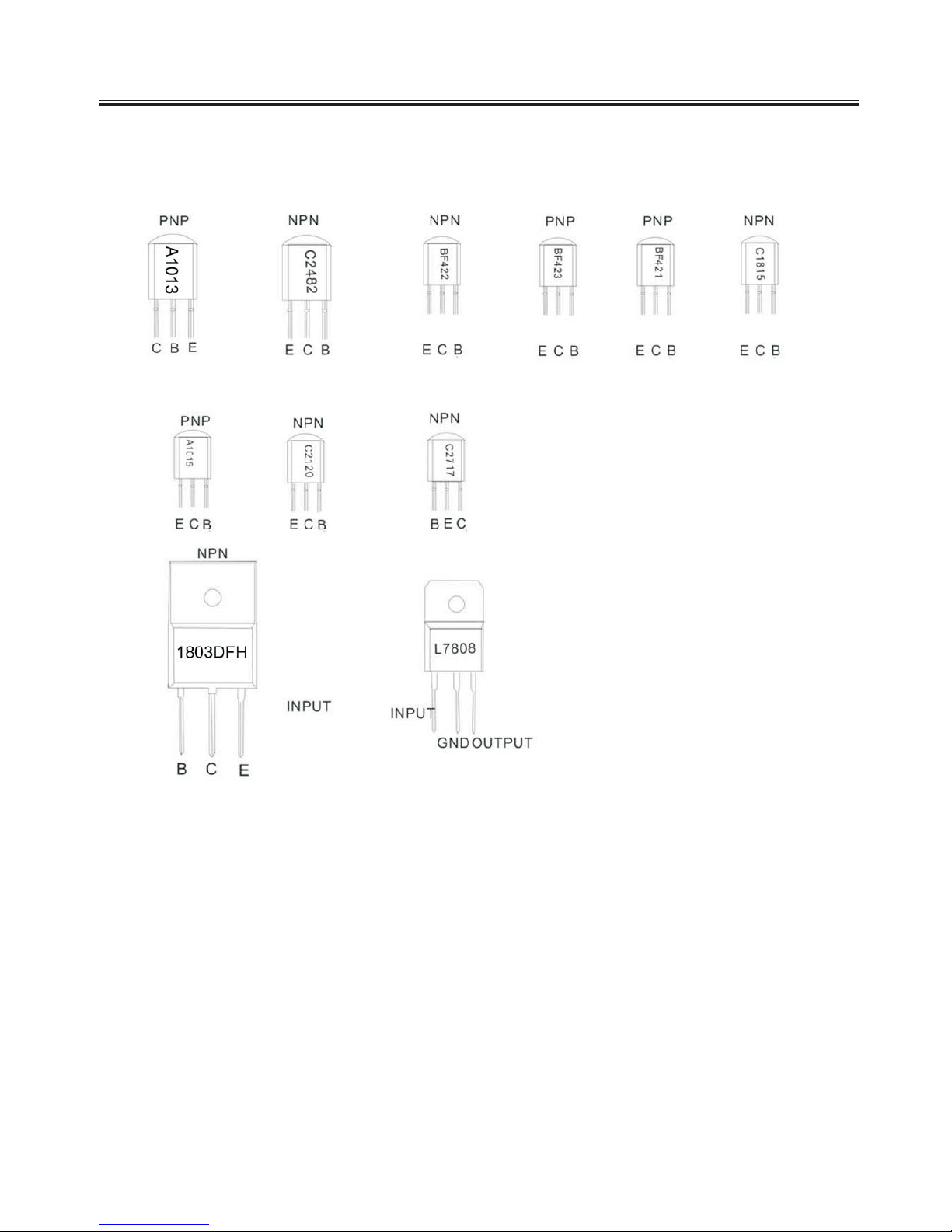
Transistor Mark
-11-

Maion PCB Top Layer
-12-
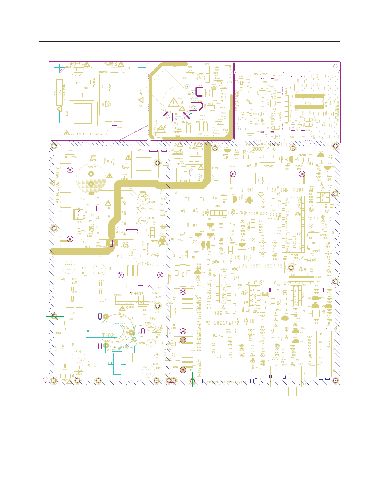
Maion PCB Bottom Layer
-13-

Service Adjustments
-14-
1. FACTORY MODE:
1. FACTORY MODE:
(1) Press the keys
P.P ,
P.P S.S
and Keys on the menu
in turn to enter the factory mode,
press the key DISPLAY to exit. .This mode is usually for R&D and engineering department use
.
(2) Press digital keys to enter every adjust page, use PROG+/-
keys to pick adjust
items, use VOL+/- keys to adjust the value.
(3) Press DISPLAY to quit factory mode.
2.B+ VOLTAGE ADJUST
2.B+ VOLTAGE ADJUST
Measure C600A +point B+ + voltage,
adjust VR641 to get proper B
+ voltage
according to CRT assembly list requirement.
3. RF AGC VOLTAGE ADJUST
3. RF AGC VOLTAGE ADJUST
(1)Receive 294.25MHz, 60dBcolor bar signal.
(2)Enter factory mode and pr
ess digital key “4”.
(3) Measure tuner AGC point vol tage, adjust AGC item till the v oltage is 2.4V,or till
picture noise just disappears
4
、
FINE ADJUST
FINE ADJUST
:
(1) FOCUS ADJUST
(1) FOCUS ADJUST
a. Receive cross-hatch pattern signal
b. Set picture to
“ RICH” mode。
c. Adjust FBT’s FOCUS knob till picture is clear
(2) SCREEN VOLTAGE ADJUST(KEY 0 )
(2) SCREEN VOLTAGE ADJUST(KEY 0 )
:
a.a.Set picture to
“ STANDARD” mode,without signal input;
b. Enter factory mode and press digital key”0”,there will be a level bright line on the
scree.
c. adjust the level bright line till it just can be seen, press PROG+ key to enter other
menu
(3) HORIZON ADJUST(KEY 1 ):
(3) HORIZON ADJUST(KEY 1 ):
Receive 50HZ monoscope PATTERN. Set TV to standard mode. Press
KEY1 to
enter factory mode
b. Adjust 5HSH(for 60Hz picture,it
s is 6HSH)to set picture hori zontal center to CRT
horizontal center.
c. Receive 60HZ monoscope PATTERN, repeat above b item
(4) VERTICAL&YUV/RGB HORIZON ADJUST(KEY2 ):
(4) VERTICAL&YUV/RGB HORIZON ADJUST(KEY2 ):
5VSL 50HZverticallinearity 5SCL 50Hz vertical slope
correction
5VSH 50HZverticalcenter 5VAM 50H zvertical siz
e
6VSL 60HZ vertical linearity 6SCL 60HZ vertical sl
ope
correction

a. Menu OSD position adjustment:
Receive 50/60HZ cross hatch pa
ttern.
Set TV standard status. Press
K
KEY 2
in factory mode, adjust
5VOF/6VOF and HOF item, to obtain
menu OSD at the center of CRT
screen;
b. LOGO position adjustment: Re
ceive 50/60HZ cross hatch pattern. Set TV
standard status. Press
KEY 7
in factory mode, adjust
XMIN,XMAX,YMIN, and YMAX item, to obtain LOGO at the center
upto 1/3 of CRT screen.
4-6-3 TELETEXT OSD position adjustment: Receive 50/60HZ TELETEX
T
signal. Set TV standard status. Press
KEY 7
in factory mode, adjust
TXMI and 5TYM/6TYM item, to obt ain INDEX at the center of CRT
screen.
(6)
White Balance Adjustment (Applied in factory)
White Balance Adjustment (Applied in factory)
(
KEY 3
KEY 3
)
Normally, this chassis can auto adjust white balance, but for s
ome CRT need to
adjust white balance carefully by hand , Set BRIGHTNESS and CONTRAST at
normal status , receive GREY SCAL and entering factory mode pre
ss KEY 3, set
WPR at 31, adjust WPG and WPR to obtain white balance.
6VSH 60HZverticalcenter 6VAM 60HZ vertical s
ize
a. Receive 50Hz cross hatch signal,set TV to STANDARD mode, adjus
t 5VSL
so that picture’s vertical line is just at the bottom of the ha
lf picture.
Adjust 5SCL to set proper verti cal linearity, Adjust 5VSH to set picture vertical
center to CRT center.
b. Adjust 5VAM to obtain picture’s
vertical re-display ratio more
than 90% .
. Receive 60Hz cross hatch s
ignal, repeat above (1),(2).
C
d
.
If necessary, fine adjust above items.
e. Receive 50HZ RGB or YUV cross hatch signal,set TV to STANDAR
D
mode,adjust 5RGH till picture hor
izontal center is at the CRT c
enter.(OPTION)
f. Receive 60HZ RGB or YUV cross hatch signal, The TV is set to the standard
mode in the factory menu, adjus
t 6RGH till picture horizontal c
enter is at the CRT
center.(OPTION)
Instruction :The parts with * should be adjusted according to whether the TV
has
RGB or YUV functipon.
(5) OSD POSITION:
(5) OSD POSITION:
Service Adjustments
-15-

Service Adjustments
-16-
(7) Focus adjust
(7) Focus adjust
:
Check the color purity of CRT , if the color purity is badness,
please adjust it as
the following items again.
a. incept point signal, make sure the TV is set to be dynamic.
b. Loosen the assemble magnetism patch fastness nip, turn the red and the
blue magnetism ring, make the two points folded at the center of the screen.
d. Take the fastness wedge of the deflexion winding DY off, lean the deflexion
winding in the level and the vertical directions gently in order to get a favorable
moving assemble, which can make the points at the edge of the screen clearer,
and rotate the fastness nip finally.
e. Insert the fastness wedge and fix it up, first, insert the left at the bottom one,
then the left at the bottom, the right at the top and the left at the top ones.
c. Rotate the red blue-green whisht assemble magnetism ring, make the red,
blue and the green point folded at the center of the screen.
5 E2PROM INITIALIZTION、
(1) E2PROM initialization (KEY 8 ):
We can use an empty E2PROM when making the sample TV or repairing,also can use the
E2PROM which has been full of data,but you must follow the steps below to initialize the E2PROM.
Press the keys P.P ,
S.S and
in
turn to enter the factory mode Press。 KEY 8,VOL +/- in turn, you
may see the OSD”BUSY” after the INIT on“”the screen About。 a while, the character BUSY will“”
disappear then, POWER OFF and ON the TV, the initialization is completed。
(2) FUNCTION SETTING (KEY 5 )
Press the keys P.P , S.S and in turn to enter the factory mode Press KEY 5 to enter the setting menu。。
b.Set values to OPTION 1- OPTION 7
c.LOGO setting when powered on or no signal Press: key SCAN in factory menu to enter the LOGO edit
mode there, are two rows the, 1
st
can set the customer's name etc and, the 2ndrow can set to display the
customer's e-mail, phone… Press。 the keys “PROG +/- ”to select the character to edit use, keys “VOL+/-”
to choose the charater.

Service Adjustments
-17-
The detailed instruction of 3P51/5P18


CONTROL PANEL BUTTONS
Power Connection
Rear View of the TV Set
(AC 220V
50/60 Hz).
1. Video / Audio input for playback for VCR.
2. Video / Audio output for TV program.
Connect the aerial or cable TV plug to the Antenna Input Socket located at the back of the TV and
connect the cable plug coming out from the TV out socket located at the devices (VCR, DVB, etc.) to this
socket as well.
Video And Audio Input/ Output Terminals
Connections To The Antenna Input Socket
Only use the adaptor supplied with this product, connect the AC plug to the socket at the back of the TV.
This TV must be operated only from the type of power source indicated on the marking label
1. Power Button
2. Power Indicator & Remote Sensor
3. Speakers
4. AV/TV Button
5. MUTE Button
6. Menu Button
7. Volume Down/Up Button
8. Program Down /Up Button
9. AV In (Option)
AV Out (Option)
YUV (Y, Cb, Cr) In (Option)
Antenna Input Socket (75 ohm)
10. AC Power Cord
11.Side AV In(Option)
S-Video(Option)
Control Location
-26-

Input and Output Terminals
-27-
Connecting the Aerial(or Cable Television Network)
75 ANT
Cable
Television
Network
To view television channels correctly ,a signal
must be received by the set from one of the
following sources:
*An outdoor aerial
*A cable television network
Plug the aerial or cable network input cable to
the 75 coaxial socket on the rear of the
television.
VIDEO
LEFT
RIGHT
AV IN
AV OU T
VIDEO
LEFT
RIGHT
VCR
Decoder/
video game device
Video disc player
Camcorder
Satellite receiver
VCR
TV
Satellite receiver
V
L
R
V
L
R
V
L
R
V
L
R

VCR
Decoder/
video game device
Video disc player
Camcorder
Satellite receiver
V
L
R
V
L
R
L
R
L
R
YC YC
S-VIDEO
L
R
L
R
Y
Cb
Cr
Y
Cb
Cr
VIDEO
LEFT
RIGHT
AV IN
LEFT
RIGHT
YCbCr IN
LEFT
RIGHT
Y
Cb
Cr
Connecting the Audio/Video Input/Outputs(option)
Input and Output Terminals
-28-

VCR
Decoder/
video game device
Video disc player
Camcorder
Satellite receiver
PERITELEVISION
VCR
TV
Amplifier
21 PIN SCART
Input and Output Terminals
-29-

PERIPHERAL EQUIPMENT CONNECTIONS
Aerial socket
Audio/ Video in sockets
There is a wide range of audio and video equipment that can be connected to your TV.
Connection diagrams at the end of this section show you where the different equipment should be
connected at the backside of the TV.
1. Connect the RF out socket of the VCR to the aerial socket on the back of the set.
2. Connect the aerial cable to the RF aerial in socket of the VCR.
3. Select the program number where the VCR channel is stored.
4. Press the PLAY button on the VCR.
1. Connect the audio/video out sockets of the VCR to audio/video in sockets of the set.
2. Press the AV/TV button to select AV.
3. Press the PLAY button on the VCR.
The VCR playback picture appears on the screen.
Precautions when connecting to other equipments
When using external equipment with this TV, please read the instruction manual of the external
equipment.
Switch off all power supplies to the equipment and TV before connection.
Always ensure that the input and output terminals are correctly connected..
Note:If you wantto watch the signals from the input jacks on the front panel,disconnect
theEuroscartsocketoftheVCRfromtheEuroscartsocketonthebackoftheset.
Input and Output Terminals
-30-

USING THE REMOTE CONTROL
Batteries
Precautions when using batteries
Precautions when using the remote control unit
NOTE:
Please follow the below instructions to install the supplied batteries into the remote control to make it
operate.
1. Remove the battery cover.
2. Insert two 1.5V (AAA size) batteries making sure
The polarity (+ or -) of the batteries
matches the polarity marks inside the unit.
3. Replace the battery cover.
Do not use old and new batteries together.
Do not use different types of batteries (for example, Manganese and Alkaline batteries)
together.
Note that there are chargeable and non-chargeable batteries. Do not attempt to charge
non-chargeable batteries.
If the remote control unit is not used for a long period of time, remove the batteries
Do not drop the remote control unit.
Do not subject the remote control unit to physical shocks.
Keep the remote control unit dry. Wetting it may cause the unit to malfunction.
Replace the batteries with new ones when operation of the unit deteriorates.
If there is an object between the remote control and the signal remote control
sensor window on the TV, the remote may not operate. Please make sure the remote
control is aiming at the remote control sensor window on the TV.
Operation Instructions
-31-

1.POWER (STANDBY) BUTTON ( )
2. MUTE BUTTON ( )
3.DIGIT BUTTONS (0-9)
4. PROGRAM SELECTION BUTTONS (--/---)
5. AV/TV BUTTON (AV/ TV)
Option
PressthisbuttontoturntheTVon/off.Press
any Number Button or Program Up/Down
Button will also switch on the TV from standby
mode.
Press this button to temporarily cut off the
sound output, press it again to restore the
sound level.
Press the number for your desired program
and the program indicator will be displayed
on the screen. To select a single-digit
program, press the corresponding number
key0-9buttonontheremotecontrolunit.
Press --/--- key to select one to three digits
entry. If you want to select0-9program
channel other than using the Digit Buttons,
please press "--/---" key until display "-" on
the screen right-top corner, then press digital
number key 0-9.If you want to select 10-99
program channel, please press "--/---" key
until display "--" on the screen right-top
corner, then press digital number key 0-9.If
you want to select 100-200 program channel,
please press "--/---" key until display "---" on
the screen right-top corner, then press digital
number key 0-9.
Inputs can be set for TV or AV mode. Press
this button to display external video signal
such as DVD, VCR or VCD video player. AV
will be displayed on he screen. Press this
button again to switch back to TV signal from
AV.
:In TELETEXT mode, used as LANG.Key.
Press this button to swith the teletext
LANGUAGE such as English or Russian.
Remote Control Buttons
2
4
5
6
879
--/---
MENU
PROG.-
VOL.+VOL.-
SCAN
LOCK
P.P.
AV/TV
0
3
PROG.+
Q.VIEW S.S.
TEXT
SUB.PAGEINDEX HOLD
REVEAL
CANCEL
SIZE
MIX
Operation Instructions
-32-

6. PROGRAM UP/DOWN BUTTONS (PROG. +/-)
7. VOLUME UP/DOWN BUTTONS (VOL.+/-)
8. MENU BUTTON (MENU)
Option
Press the Program Up Button to select the program
forwards.Press the Program Down Button to select
the program backwards.
Press Volume +/- Buttons to adjust sound level.
Press "MENU" button to display the OSD (OnScreen Display) menu for adjusting the image,
sound and functions. Pressing this button again to
out from the OSD.
Please refer to page 15-19 for the details.
: In TELETEXT mode, Press this button to
swith the teletext type such west/east type.
9. PERSONAL PRESETS BUTTON (P.P.)
10.QUICK VIEW BUTTON (Q.VIEW)
11. DISPLAY BUTTON ( )
12. SLEEP TIMER BUTTON ( )
You can select USER, STANDARD, SOFT or RICH
mode by pressing this
button.
Press this button to return to the previously viewed
program.
Press this button sequentially to display the current
program number, color system and sound system
on the screen.
If you do not set the time, " --:--" will display on the
screen
Press the "Sleep Timer" button on your remote
control to start setting the automatic sleep timer.
Press the button to adjust the time in increments of
30 minutes, from 0 to 180 minutes. When the preset
time runs to 0, TV set will go into standby mode. To
switch off this function, press this key step by step
until " OFF" is displayed on the screen.
l
2
4
5
6
879
--/---
MENU
PROG.-
VOL.+VOL.-
SCAN
LOCK
P.P.
AV/TV
0
3
PROG.+
Q.VIEW S.S.
TEXT
SUB.PAGE
INDEX
HOLD
REVEAL
CANCEL
SIZE
Remote Control Buttons
MIX
Operation Instructions
-33-

The TV set can provide the locked key for control or
prevent your children from watching the program.
Press the "LOCK" button on remote control unit.
The key locked symbol( ) will be displayed on the
screen for five seconds and entered into the child
locked mode. While in Lock mode, any keys on the
TV set will be disabled. Except the key on the
Remote control
Press again the 'LOCK" button on the remote control
unit to cancel this function.
Press the SCAN button to automatically browse
every channel which you have stored.
Press this button to select the correct sound system
5.5M 6.0M 4.5M 6.5M
In NICAM mode, press this button to change the
sound station.
In TV mode, the(GREEN) / (BLUE) buttons has the
same function as PROG+/- buttons; the (RED)/
(YELLOW)buttons has the same function as VOL+/button.
In TELETEXT mode, press these colour buttons ,the
color of page no of teletext will change to the same
colour as that of the buttons.
13.LOCK BUTTON
SETTING UP THE CHILD LOCK FUNCTION:
RELEASE CHILD LOCK:
14.SCAN BUTTON
15.SOUND SYSTEM BUTTON(S.S)
16.STEREO/MONO DUAL(CHI/II)(TELETEXT
OPTION)
17.COLOUR BUTTONS(RED/YELLOW/GREEN/
BLUE)(TELETEXT OPTION)
2
4
5
6
879
--/---
MENU
PROG.-
VOL.+VOL.-
SCAN
LOCK
P.P.
AV/TV
0
3
PROG.+
Q.VIEW S.S.
TEXT
SUB.PAGE
INDEX
HOLD
REVEAL
CANCEL
SIZE
Remote Control Buttons
MIX
Operation Instructions
-34-

*Picture mode RICH,SOFT,STANDARD are fixed
by factory, all the change of these settings will be
saved into the USER mode automatically.
In TELETEXT mode, used as INDEX key.
INDEX: Press INDEX button to obtain the index page.
In TELETEXT mode, used as REVEAL key.
REVEAL: Sometimes the answers of quizes, jokes
etc are hidden. Press REVEAL button to reveal
the hidden information.
In TV mode, used as PICTURE menu command; in
TELETEXT mode, used as SIZE key.
SIZE: The top or button half of any page can be
enlarged by pressing this button.
In TELETEXT mode, used as HOLD key.
HOLD: Sub-pages will scroll automatically. Press
HOLD button a hold a sub-page.To release the page.
Press HOLD again.
In TELETEXT mode, used as SUB.PAGE key.
SUB.PAGE: Some pages attach sub-page,Page
number may contain several subpages which are
automatically paged by the TV station. Press this
button once.0001 will be displayed on screen, use
number key(0-9)to look for other sub-pages if
available, If there is no sub-page,**** will be
displayed. To cancel this, press this button again.
Press this button to display TELETEXT signal, mix
TELETEXT page with TV signal and return to TV.
NOTE: To avoid mixing of External R.GB while
viewing teletext. Disconnect scartplug or swith off
external R.GB source(This key only use for
TELETEXT mode).
“”
“”
18.INDEX BUTTON(TELETEXT OPTION)
19.REVEAL MENU BUTTON(TELETEXT OPTION)
20.SIZE MENU BUTTON(TELETEXT OPTION)
21.HOLD BUTTON(TELETEXT OPTION)
22.SUB.PAGE BUTTON(TELETEXT OPTION)
23.TEXT/BUTTON(ON/MIX/OFF)(TELETEXT
OPTION)
2
4
5
6
879
--/---
MENU
PROG.-
VOL.+VOL.-
SCAN
LOCK
P.P.
AV/TV
0
3
PROG.+
Q.VIEW S.S.
TEXT
SUB.PAGE
INDEX
HOLD
REVEAL
CANCEL
SIZE
Remote Control Buttons
MIX
Operation Instructions
-35-

24.CANCEL BUTTON(TELETEXT OPTION)
In TELETEXT Mode, used as CANCEL key.
CANCEL: If you want to watch TV but not cancel
the TELETEXT mode completely. Press the
CANCEL button. When the last selected page is
updated, the page number will be appeared at
the top of the TV screen press the CANCEL
button again to reveal the page.
2
4
5
6
879
--/---
MENU
PROG.-
VOL.+VOL.-
SCAN
LOCK
P.P.
AV/TV
0
3
PROG.+
Q.VIEW S.S.
TEXT
SUB.PAGE
INDEX
HOLD
REVEAL
CANCEL
SIZE
Remote Control Buttons
MIX
Operation Instructions
-36-

MENU SYSTEM
This TV allows you to adjust the settings from the menu screens.
* In the AV mode, menus appear the same as in TV mode except the Install menu.
Picture
Sound
Features
Timer
TINT
SHARPNESS
BRIGHTNESS
COLOR
VOLUME
LANGUAGE
TREBLE
BASS
BALANCE
COLOR SYS
SOUND SYS
TIME
STOP TIME
CH SWITCH
SWITCH TO
Install
SURROUND
CONTRAST
CALENDAR
MANUAL STORE
FINE TUNE
PROG NO
AUTO STORE
SOUND MODE
GAME
START TIME
SKIP
Operation Instructions
-37-

Picture Menu
Sound Menu
PICTURE
CONTRAST
BRIGHTNESS
COLOR
SHARPNESS
TINT
55
55
55
50
00
SOUND
VOLUME
TREBLE
BASS
BALANCE
SURROUND
SOUND MODE
51
00
00
00
OFF
STANDARD
Press the MENU button to enter the menu screens for the following
settings.
Select the desired item using the PROG.+/-Buttons.
Use the VOL. +/- buttons to adjust the item settings.
The item selected will be highlighted in red
* The menu screen will time out automatically after few seconds if it is left
idle on the screen.
PICTURE Menu -> SOUND Menu (option) -> FEATURES Menu -> TIMER
Menu -> INSTALL Menu -> EXIT
-
-
""
You can select CONTRAST, BRIGHTNESS,
COLOR, SHARPNESS, and TINT items by
pressing PROG. +/- Buttons, and pressing the
VOL.+/- Buttons to adjust the item of which you
selected.
PresstheVOL.+/-buttonstoenhance or reduce
the contrast between objects and the background
from 00 to 100 .
UsingtheVOL.+/-buttonstoadjust the lightness
and darkness of the picture from 00 to 100 .
PresstheVOL.+/-buttonstoincreaseordecrease
the color saturation from 00 to 100 .
Adjust the outline of objects to either sharpen or
more dull from 00 to 100 .
Adjust the color of objects from 50 to +50 ,
making them more red or green for a more natural
look.
Press VOL +/- buttons to adjust the Volume
between 00 and 100 .
Press VOL +/- buttons to adjust desired Treble
volume of sound b
1.CONTRAST
2.BRIGHTNESS
3.COLOR
4.SHARPNESS
5. TINT (NTSC Only)
1.VOLUME
2.TREBLE
"" " "
"" " "
"" " "
"" " "
"" " "
"" " "
"" " "etween -10 and +10 .
Operation Instructions
-38-

Features Menu
FEATURES
LANGUAGE
COLOR SYS
SOUND SYS
CALENDAR
GAME
ENGL ISH
AUTO
3.BASS
Press VOL +/- buttons to adjust desired Bass volume of sound between
"" " "-10 and +10 .
4.BALANCE
Press VOL +/- buttons to adjust the Balance between L50 and R50 ."" " "
5.SURROUND
You can select to turn ON or OFF the Surround.
6.SOUND MODE
Press VOL +/- buttons to select the Sound Mode to STANDARD, MUSIC,
THEATER, USER.
Note:TREBLE,BASS,BALANCE,SURROUND,SOUND MODE have function
only for TONE-CONTROL.
1.LANGUAGE
2.COLOR SYS
3.SOUND SYS
You can change menu language in this item. Press
VOL. +/- Buttons to select your desired language.
All the on screen displays will appear in the
selected language.
Press VOL +/- buttons to change the color system
to AUTO, PAL,N4.43,NTSC,SECAM
Press the VOL.+/- Buttons, you can change the
Sound System to 6.0M ( I), 6.5M ( D/K), 4.5M ( M)
and 5.5M ( B/G).
B/G: PAL B/G, SECAM B/G
I: PAL I
D/K: PAL D/K, SECAM D/K
M: NTSC-M
Operation Instructions
-39-

4.Calendar (Option)
-Press VOL +/- button to enter into Calendar menu.
-Press PROG +/- buttons to select Year, Month and Date. Press VOL +/-
button to adjust the value.
-Press MENU button again to return.""
5.Game Moving Cube (Option)
Press the PROG. +/- to select the Game function under the Features Menu.
Press VOL +/- buttons to enter the Game OSD (On Screen Display) menu.
Game Rules: There are total 16 levels of the game. The player will win when
moving all the pink cubes to the red box.
-Press PROG +/- buttons to move UP and DOWN, press VOL +/- to shift
between right and left.
-To next stage of the game, press P.P button.""
-To start a new game, press MUTE .""
-To exit the game, press MENU button.""
Timer Menu
TIMER
TIME
START TIME
STOP TIME
CH SWITCH
SWITCH TO
-- --
-- --
-- --
-- --
--
--------
1. TIME
2. START-TIME
3. STOP-TIME
4. CH SWITCH
5.SWITCH TO
NOTE:
To adjust the current time by this item. Press the
VOL. - button to set hour, and the VOL. +
button to set minute.
To set the time when the TV set to turn on
automatically.
To set the time when the TV set to turn off
automatically.
To preset the time that the TV will switch to the
selected channel (Position) automatically.
To set the program that will switch automatically
at the CH SWITCH.
All the timer functions will only be
effective if the power of the TV set is switched
off using the remote control unit. If the power
is switched off by the power button on the TV
set or a power failure occurs, the timer will
be reset.
"" " "
Operation Instructions
-40-

Install Menu
INSTALL
AUTO STORE
MANUAL STORE
FINE TUNE
PROG NO.
SKIP
00
OFF
1.
2. MANUAL STORE
3. FINE TUNE
4.PROG NO
5
Press VOL.+/- Buttons to start searching. The
VOL- button for backward search; the VOL+ button
for forward search. When a TV station signal is
received, the searching will stop automatically.
You can use this FINE tuning process for fine
adjustment by pressing VOL.+/- Buttons. Normally
fine tuning is only necessary if reception is poor.
Up to 200 TV channels can be stored by program
numbers (0 to 200). By pressing VOL.+/- Buttons
(or number keys) in this item to select channel
number. You can store the channel number, which
are watching, and change the channel number.
Once you have preset the channels, you will be
able to use the PROG. +/- or NUMBER buttons to
scan the channels you have programmed.
AUTOSTORE
Press VOL.+/- Buttons,the TV setwill automaticaly
search from V-L band to U band.The channels are
stored in the order in which they appear in the
frequency bands.
""
""
You can skip unnecessary program channels of
your choice not to be displayed during viewing
and scanning when pressing the PROG -/+
buttons.Select "Skip Del" by pressing VOL.+/Buttons to select the channel that would like to
skip from the channel scan operation.
.SKIP
.
Operation Instructions
-41-

TROUBLESHOOTING
The following problems do not always indicate a hardware failure. Therefore, please use the
troubleshooting guide below before calling for repair service. If, after following the guide none of the
remedies work, unplug the TV and call for service.
Make sure the power cord is plugged in,
then press POWER button.
Check battery in the remote control.
(Maybe batteries are dead.)
Ensure the TV power is ON (Indicated
by the green power indicator on the
front of the unit).
Check antenna/ cable connections.
Try different channel.
Maybe sound is muted. Try pressing
VOL+ button is not set to minimum.
Try another channel.
Check the AV cables for disconnection.
Maybe the TV is being affected by
interference from automobiles, trains,
high-voltage transmission lines, neon
signs or another sources of interference.
Try redirecting or relocating your antenna
to reduce the affects of the interference.
Change channels to confirm if the
symptom is still present.
Try another channel.
Check antenna connections.
If using VCR, check TV/VCR button.
Adjust fine tuning control.
Probably local interference, such as an
appliance.
When the VCR test signal (TSG) is
received, the lower side of the test
pattern is distorted as shown in the
figure. This is not a malfunction and the
playback picture is not influenced by it.
That channel may be locked out with
SKIP CHANNEL function.
Problem Checks and Adjustments
TV will not turn on
No picture, no sound
No sound, picture OK
Spots on the screen (Snow)
Poor reception of broadcast
channels
VCR
Cannot select a certain channel
Operation Instructions
-42-

Check for any obstacle between the
remote control and the remote control
sensor window.
Maybe batteries are dead. Try replacing
batteries with new ones.
Check for incorrect battery orientation.
Please change the direction, height or
positionof the antenna. Reflections from
building or mountains might cause this
phenomenon. A highly directional
antenna may improve the reception.
Check whether all the picture adjustments
have been properly performed.
Enter into the (Picture mode) inside the
menu to select a different picture set-up.
Remote Control does not operate
The picture is doubled or tripled
(GHOST)
Degraded colours or tints
Operation Instructions
-43-

1
2
3
4
5
A
B
C
D
E
5
4
3
2
1
E
D
C
B
A
Scale Sheet
Size FCSMNo. DWGNo. Rev
0of0
A0
R453
270 1W
C456
0.1uF/100V
100V
R460
100
C461
1nF
R459
1K8
50V
100V
Q401
C2482
R405
5K6
C402
2200pF
T401
500V
C403
220pF
500V
C404
4.7uF
50V
N401
D2553
R454
33
R433
0.33
D433
BA158
C432
8n2
C431
6n8
D430
BY228
2KV 2KV
C433
33nF
D431
RU4B
L430
20uH
L440
790uH
C463
0.33uF
250V
R440
6.82W
R441
75K
C441
0.01uF
50V
Q440
F630
ZD440
8.2V
R443
470
0.01uF
C437
10uF
C436
560pF
R420
1K
C443
0.056uF
D402
1N4148
FBP
B+
180V
R450
0.22
470pF
D450
BYW36
C453
1000uF/25V
0.1uF
250V
SCREEN
FOCUS
HVTO CRT
CN301
H-DEF
+14V
10
814
7
6
3
6
T402
FLYBACK
R423
3.92W
R424
1K
R416
1K
+135V_VCC
ABL
C410
10uF/16V
1
2
3
4
CN401
TOCRT
+48V_VCC
R406
1K/1W
D404
1N4148
R419
560K
ZD402
18V
X-ray
X-ray
1W
2KV
630V
100V
50V
250V
HEATER
+13V
ABL
35V
R421
180
R422
680
R404
100
R403
NC
!
!
!
!
!
!
!
!
!
1
2
CN601
F601
T3.15A
L601
15mH
C601
0.22uF/250V
T601
R601
2.2M1/2W
C602
0.22uF/250V
D
1
S/GND
3
VCC
4
OLP/SS
5
FB
6
OCP/BD
7
IC601
STR-W6556A
RL601
RELAY
C603D
4700pF
C603C
4700pF
C603B
4700pF
C603A
4700pF
C607
220uF
IC622
OPTOISO1
R607
22
D605
BA158
C609
10nF
R610
8.2M
C610 0.0022uF
C627
1000uF
25V
R622
0.222W
D623
RU4YX
C624
680pF500V
C626
1000uF
16V
D622
BYW36
C623
680pF500V
R621
0.222W
D621
BA158
C620
680pF500V
C622
470uF
50V
D620
RU4B
C462
560pF2KV
200V
<45V>
<12V>
<20V>
<135V>
R630
680
IC621
SE120
Q621
C1815
Q622
C1815
Q624
A1013
D626
BA158
R639
10K
R649
2K2
R627
6.2K
Q623
C1815
J615
10K
+135V_VCC
+32V_BT
L:STANDBY
H:WORKING
D627
1N4148
R640
0
C634
0.1uF
R644
10K
+12V_VCC
+8V_VCC
R645
390
+12V
AC250V
AC250V
450V
AC90-270V
16V
16V
50V
ZD620
5V1
L604
R631
1K
CN603
DEGAUSSING
Rs
Rp
1
23
9RM
PTC601
BL
BGR
GND
HEATER
GND
+180V
CRT
R
G
B
CRT AMPLIFY CIRCUIT
H501
H502
STANDBY1SCL2SDA3AV3/TUNING4SCARTID5KEY6VOL7BAND8VssC/P9MUTE10PAL/NTSC11VssA12SECPLL13Vp214DECDIG15PH2LF16PH1LF17GND318DECBG19AVL/EWD20VDRB21VDRA22IF123IF224IREF25VSC26TUNERAGC27AUDEEM/SIF128DECSDEM/SIF229GND230SNDPLL/SIFAGC31AVL/REFO
32
H.O UT
33
FBISO
34
AUDEXT/QSSO
35
EHTO
36
PLLIF
37
IFVO/SVO
38
Vp1
39
CVBSINT
40
GND1
41
CVBS/Y I N
42
CIN
43
AUDOUT/AMOU T
44
BLANK
45
R/VIN46G/YIN
47
B/U IN
48
BCL I N
49
BLANKING
50
ROUT
51
GOUT
52
BOUT
53
VddA
54
VpE
55
VddC
56
OscGnd
57
XTAL I N
58
XTALOUT
59
RESET
60
VddP
61
AV162AV2
63
IRin
64
IC201
TDA83731
12345
E6Vee7Vss
8
9101112131415
Vdd
16
0
1
2
3
0
1
2
3
IC761
HEF4052
C765
4700PF
SPL
4RM10W
SPR
4RM10W
CN760
SW2
SW2
LOUT
Q761
C1815
D763 IN4148
R766
47K
R137
1K
D762
1N4148
MUTE
+8V_VCC
1
2
3
4
5
6
7
8
9
1
2
1
2
IC760
TFA9843AJ
---10W
C766
4700PF
ROUT
R770 1K
R769 1K
PWM
Lout
GND
VI
VO
VIG
VOG
BL
V/R
BG
RGND
NC
Y/G
NC
GGND
OPT
U/B
Lin
BGND
GND
LO
Rin
RO
R643
47K
1
2
3
4
5
6
7
8
9
10
11
12
13
14
15
16
17
18
19
20
21
P701 21PIN
ZD703
8V2
ZD701
8V2
ZD714
8V2
8V2
ZD713
8V2
8V2
ZD705
8V2
R721
75
R715
75
R722
75
R723
75
R701
47K
R702
47K
12345
E6Vee7Vss
8
9101112131415
Vdd
16
0
1
2
3
0
1
2
3
IC762
HEF4052
Q702
C1815
R708
20K
R705
1K8
R706
1K8
R709
20K
Q701
C1815
R710
20K
R707
20K
AGC
1
NC
2
SAS
3
SCL
4
SDA
5
NC
6
BM +5V
7
NC
8
BT +33V
9
IFGND
10
IF
11
U101
38.9MHz
R113
47K
C110
NC
C111
100pF
R111
100
1
2
3
4
5
SAW101
SW02B
C105
10nF
Q101
C2717
R102
1K5
R106
1K
L101
10uH
R105
22
R103
5.1K
C101
0.01u
IC102
+33V
+
C156
22u/50V
R101
75
R112
100
C103
10nF
C130
220nF
C131
2200p
C132
4n7
+
C133
1uF/50V
R138
18K
C128
10nF
+
C129
10uF/16V
L205
10uH
+8V
C120
0.1U/63V
+
C119
10uF/16V
C127
220nF
X101
12MHz
C147
33pF
C148
33pF
+3.3V
L105
10uH
+
C150
100uF/16V
+
C145
100uF
C149
10nF
C146
0.1uF
L106
10uH
C135
0.1U/63V
R151
39K
C139
330pF
C138
1.5nF
R139
2.7K
C136
2n2
HY
R149
3.3K
R148
3.3K
R144 100
R143
100
R142
100
GND
R141
10K
+8V
ZD104
8V2
1
2
3
4
5
BL
R
G
B
C727
0.1uF
R414
39K
R425
27K
ZD108
8V2
ZD107
8V2
ZD106
8V2
C726
0.1uF
C725
0.1uF
R724
33K
+
C116
1uF
+8V
Q104
C1815
+8V
R729
1K2
Q105
C1815
R728
1K
GND
GND
R127
100
R126
180
L103
8.2uH
XT165
XT-6.5
Q107
C1815
XT160
XT-6.0
XT145
XT-4.5
Q703
C1815
R711
75
GND
R124
4K7
R123
4K7
GND
XT155
XT-5.5
R713
20K
R712
R451
0.22
D451
BYW36
470pF
0.1uF
C452
1000uF/25V
-13V
WP
1
n.c.
2
A2
3
Vss
4
Vdd
8
PTC
7
SCL
6
SDA
5
IC102
24C08
R133 100
R134
100
C118
100nF
R130
3.3K
R131
3.3K
C117
100uF/16V
R132
3.3K
ZD706
8V2
ZD709
8V2
ZD711
8V2
R780
47K
R777
47K
R778
75
R125
220
R147
390
C144
0.1U/63V
C407
NC
R413
100K
R418
NC
ABL
R135
47
R122
10K
BROWN
BLUE
N
L
R603
VDR601
GASDISCHARGE
TUBE
L602
PFC15mH×2
D603
123
M001
RD5
3K3
RD6
1K8
RD
3K3
RD4
2K2
RP1
100
1
2
3
4
5
RD9
0
RD8
820
RD7
1K5
KEYBOARD CIRC UIT
LED
SW005
MENU
KEY
5V
IR
LED001
LED
SW006
SLEEP
SW007
MUTE
SW008
TV/AV
SW003
VOL-
SW002
PRO+
SW004
VOL+
SW001
PRO-
RD2
5K6
RD11
100
CR1
10uF/16V
GND
SCIN_L
1
P1
2
MIN_L
3
C_SMO
4
MIN_R
5
V_P
6
SCOUT_R
7
GND
8
MOUT_R
9
LIN_R
10
C_BR1
11
C_BR2
12
N.C.
13
C_TR
14
LOUT_R
15
SCL
16
SDA
17
LOUT_L
18
C_TL
19
N.C.
20
C_BL2
21
C_BL1
22
LIN_L
23
MOUT_L
24
MAD
25
SCOUT_L
26
C_PS2
27
AIN_L
28
C_PS1
29
AIN_R
30
P2
31
SCIN_R
32
IC740
TDA9859
VEO
VEI
Cnr
Cm
Cdec
AGND
DGND
SDA
SCL
Vcc
COMP
Vcap
Cp1
Cp2
Cph
Cadj CER
Cmo
Css
Cr
OUTR
Csde
SAP
Vref
CL
Cnd
OUTL
MAD
Ctw
Cts
Cw
Cs
123456789101112131415
16
171819202122232425262728293031
32
IC801
TDA9850
1
outR
2
Vdda1
3
Vssa1
4
Vssd1
5
Vddd1
6
Vssd2
7
n.c.
8
TP2
9
Nicam
10
11
Pclk
12
ADDR1
13
XTALO
14
XTALI
15
TP3
16
TEST2
17
I_ref
18
ADDR2
19
Vssa2
20
Vdec
21
test1
22
23
V_ref1
24
SIF1
25
CRESET
26
Vssa3
27
Vdda3
28
SCL
29
SDA
30
SDD
31
WS
32
33
34
Vddd335Vssd336P137MONOIN38EXTIR39EXTIL40V_REF241P242OUTM
43
44
TP1 SIF2
SCK
Sysclk
Vssa4
out_L
TDA9874
1
2
3
4
5
6
7
8
9
10
11
12
13
14
15
16
17
18
19
20
21
P701 21PIN
C604
1000pF
C606
470pF
R608
2K2
C600
0.1uF/250V
R
L
GND
VinVOVIG
VOG
BL
R
BG
RG
NC
G
NC
GG
OPT
B
LI
BG
GND
LO
RI
RO
P702
S-VHS
VIN
LIN
RIN
L
P701
ZD702
8V2
Y
U
V
P701
R
Vout
Lout
Rout
P701
ZD712
8V2
ZD708
8V2
ZD710
8V2
R775
47K
R776
47K
R719
75
VIN
LIN
RIN
P701
ZD707
8V2
R779
75
SIDE AV IN
REAR AV IN
BCL
BLANK
V/Rin
Y/Gin
U/Bin
CIN
CVBS/Y IN
C?
220PF/50V
R413
100K
R412
27K
C818
100PF
R807
100
R806
100
R805
10
R804
8K2
C803
10uF
C804
10uF
L803
10uH
L802
10uH
C820
0.1uF
C821
0.1uF
C819
100PF
GND
GND
GND
GND
GND
X801
24.576M
GND
C811
1uF
GND
C814
0.1uF
C812
47PF
L801
10uH
C813
1uF
GND
C817
10nF
+
C805
47uF
C816
100nF
L804
10uH
L110
10uH
+
C802
10uF
GND
+
C815
10uF
C806
100nF
R803 100
R802 100
C814
10uF
C815
0.1uF
C816
4.7uF
C803
4.7uF
C819
100uF
C806
4.7uF
C807
4.7uF
C818
100uF
C809
10uF
C827
10uF
C805
10uF
C810
10uF
C824
2.2uF
C823
2.2uF
R805
100
R806100
R802
8K2
R801
2K2
R803
150
C802
0.47uF
C804
0.22uF
C821
1uF
C817
0.1uF
C808
15nF
C822
1uF
C828
0.1uF
C813
47nF
C811
1uF
C812
1uF
X801
503KHz
C409
0.1uF
+20V_VCC
RI
RO
Rout
Lout
Lin
R768
100K
50V
R764
10K
R763
15K
C760
10uF/16V
D761
1N4148
INP
7
INN
6
Vout
5
VP4-13V
4
Vp3pump
3
VP3-
2
VP1+13V
1
IC301
TDA4863AJ
R461
5.6 1/4W
5
6
J408
1K8
2W
R457
100
C460
1nF/50V
VDRB
C459
0.1uF/100V
R452
5.6
R462
1
R463
220/2W
C455
100uF/50V
D452
BA158
2W
R417
5K6
8V
R412
27K
R407
22K
R409
27K
ZD401
8V2
C444
27PF/50V
AFC
R727
100
ZD102
5V1
R731
820
J743
10K
C740
100uF/16V
ZD715
8V2
R748
0
C746
68nF
C745
18nF
R?
RES
C748
5n6
C752
6n8
C753
0.1uF/63V
C754
68nF
R742
15K
C744
15nF
C743
15nF
AUDIO L
AUDIO R
SDA
SCL
+8V_VCC
C807
100pF
C808
100pF
C826
100pF
C825
100pF
R804
10
In
Out
Gnd
IC802
L7809
Q801
C1815
C829
1uF
R807
47K
R808
47K
R810
1K
C801
1uF
MTSoutR
NICAMout R
SCL
SDA
+12V
QSS
SCL
SDA
C109
10uF
C112
100pF
C113
220uF
ZD101
5V1
R109
10K
R110
180
1
R108
33
R510
22
Q504
C4544
R511
2K2
R512
22
R513
270
D503
1N4148
C502
470PF
2
R515
15K
Q506
BF420
Q505
BF421
1
R516
220
D504
BA158
R517
2K7
KR
R527
2K7
R508
2K7
1
R514
270
R521
22
Q507
C4544
R520
2K2
R522
22
R523
270
D505
1N4148
C503
470PF
2
R525
15K
Q509
BF420
Q508
BF421
1
R526
220
D506
BA158
1
R524
270
R501
22
Q501
C4544
R502
2K2
R504
22
R503
270
D501
1N4148
C501
470PF
2
R506
15K
Q503
BF420
Q502
BF421
1
R507
220
D502
BA158
1
R505
270
ZD501
8V2
C508
82PF
KG
KB
C507
NC
C506
NC
2
R528
220K
L501
10uH
SCREEN
FOCUS
R401
4K7
+8V_VCC
R432
270
C442
2200PF
D432
BA158
R430
15K
C406
1uF
!
!
!
L431
160uH
C464
0.18uF
FOR SLIM TUBE
S
C108
100pF
C107
100pF
C603
0.22uF
AB
C
D
2
R602
200K
D604
0
C605
0.1uF
R604
39K
100V
ZD602
18V
R606
6K8
R605
220
C608
10uF
3
R609
0.18/ 5W
C632
47uF
250V
C629
1500uF
50V
R633
5K1
50V
R647
0.51 2W
C625
1000uF
16V
C438
2n7/2KV
C435
0.47uF
C465
0.47uF
L432
1.12mH
ZD103
8V2
+3.3V
C140
4.7uF
R140
100
CN102
R725
10K
8V
TVAUDIO OUT
TVCVBS IN
X-RAY
AFC
H-out
Q103
C1815
R119
3K3
R115
4K7
+5V
SYSTEM
SYSTEM
R804
10
In
Out
Gnd
IC801
78L05
+5V
+5V
CVBSOUT
AV O U T
YUV
STANDBY
SCL
SDA
KEY
VOL
MUTE
EW
VDRB
VDRA
IF
AGC
+8V_VCC
VIDEOSWITCH
AUDIO SWITCH
C778
10uF
C770
10uF
C773
10uF
+8V_VCC
C777
10uF
C772
10uF
C774
10uF
C785
10uF
CIN
SIDEL
SIDER
REARR
REARL
C719
10uF
C717
10uF
C716
10uF
L
R
NICAMout L
MTSout L
C775
10uF
C771
10uF
TVR
TVL
TVL
TVR
TVR
TVL
TV L+R
A2
A1
A2
A1
C741
10uF
C742
10uF
R745
47K
R746
47K
R744
47K
R747
47K
AUDIO L
AUDIO R
C720
10uF
C710
470uF
R717
68
R?
ELECTRO1
R?
ELECTRO1
C708
10uF
C707
10uF
A2
A1
C780
100uF
C779
10uF
C784
10uF
CVBS/YI N
+8V_VCC
TVCVBS OUT
TVCVBS I N
CVBSOUT
REARAV
SIDEAV
SCART1AV
TV
OUT
OUTR
OUTL
AUDIOR out
AUDIO Lou t
VIDEOOUT
BLANK
OPTION
OPTION
V/Rin
Y/Gin
U/Bin
MTS BOARD
NICAM
BOARD
TONE CONTROL
-14V
VDRA
C440
4.7uF
EW
H-out
+8V_VCC
C445
2n2F/100V
AFC
AFC
onlyfor scart
onlyfor scart
onlyfor scart
RCA:
R724 33K
R725 10K
SCART:R724 10K
R725 75
47uF
C405
C105
10nF
R107
470
C106
10nF
1
2
3
4
5
SAW102
Q9362M
C137
10uF
SIF
C102
10nF
L102
31.9MHz
R116
10K
C115
10nF
Q102
C1815
R117
10K
AGC
SCL
SDA
+8V_VCC
+32V_BT
+5V
+5V
IF
SIF
SYSTEM
NTSC
NICAM
NONICAM
NTSC
NTSC
Q106
C1815
R121
10K
R120
1K
KEY
+5V_VCC
C728
100uF
Q626
C1815
8
9101112131415
16
1234567
T603
TRANSFORMER
C621
100uF
R624
0.222W
C641
2200uF
ZD621
3V9
ZD622
3V9
R638
22
R650
430
In
Out
Gnd
IC104
L7808
R632
1
C628
1000uF
25v
Q625
C1815
C640
220uF
C639
47uF
R114
39K
IC103
33V
C114
47uF
R635
22K
R634
10K
R648
22K
+5V_VCC
ZD105
5V1
+3.3V_VCC
+20V_VCC
+48V_VCC
STANDBY
R765
1K
R771
10K
C761
1uF
R145
22K
Q760
A1015
C750
1uF
C749
1uF
C764
47uF
C767
220uF
C769
470uF
C768
470uF
D403
8V2
EHT
FOCUS
SCREEN
EHT
+5V_VCC
UPDATE :
2007-01-16
1
3
4
5
CN602
CN604
L
L
N
N
R600
NTC
5RM
FORCB
FOREMC
8RM6W
8RM6W
TFA9842AJ---6W
Quadro 3P19E Chassis
 Loading...