

Quadro AC-35CH-FF BIO Nordic, AC-35CH-FC BIO Iceberg, AC-51CH-FC BIO Iceberg Installation Manual
AC-3 5CH-F F BIO Nor dic
AC-3 5CH-F C BIO Ice berg
AC- 51CH- FC BIO Ic eberg
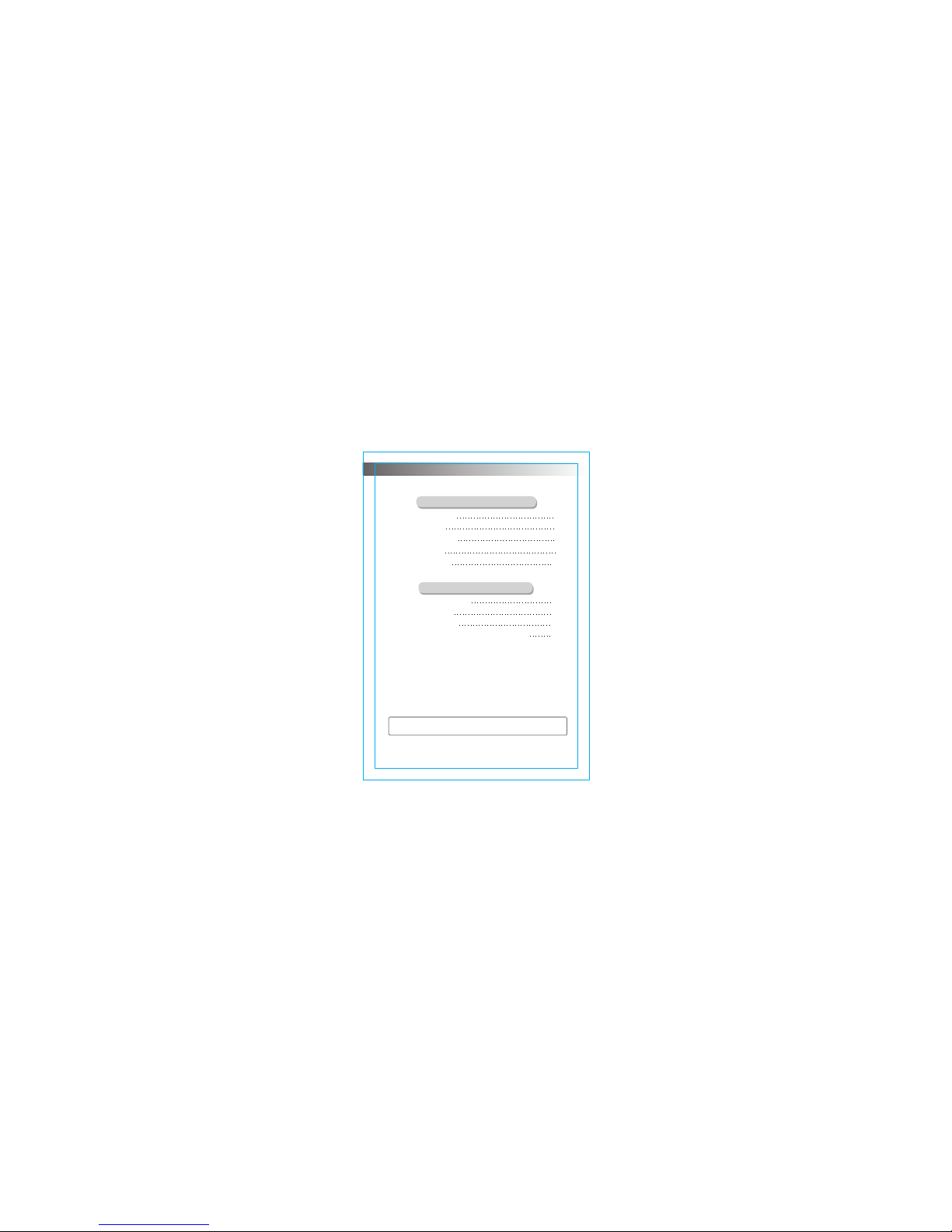
Notices for installation
Install indoor unit
Install outdoor unit
Check after installation and test operation
1
6
8
10
12
15
18
21
Installation service
9
CONTENTS
Operation and maintenance
Safety Precautions
Notices for use
Names of each part
Clean and care
Troubleshooting
Note: All the pictures in this manual are just schematic diagrams,
the actual is the standard.
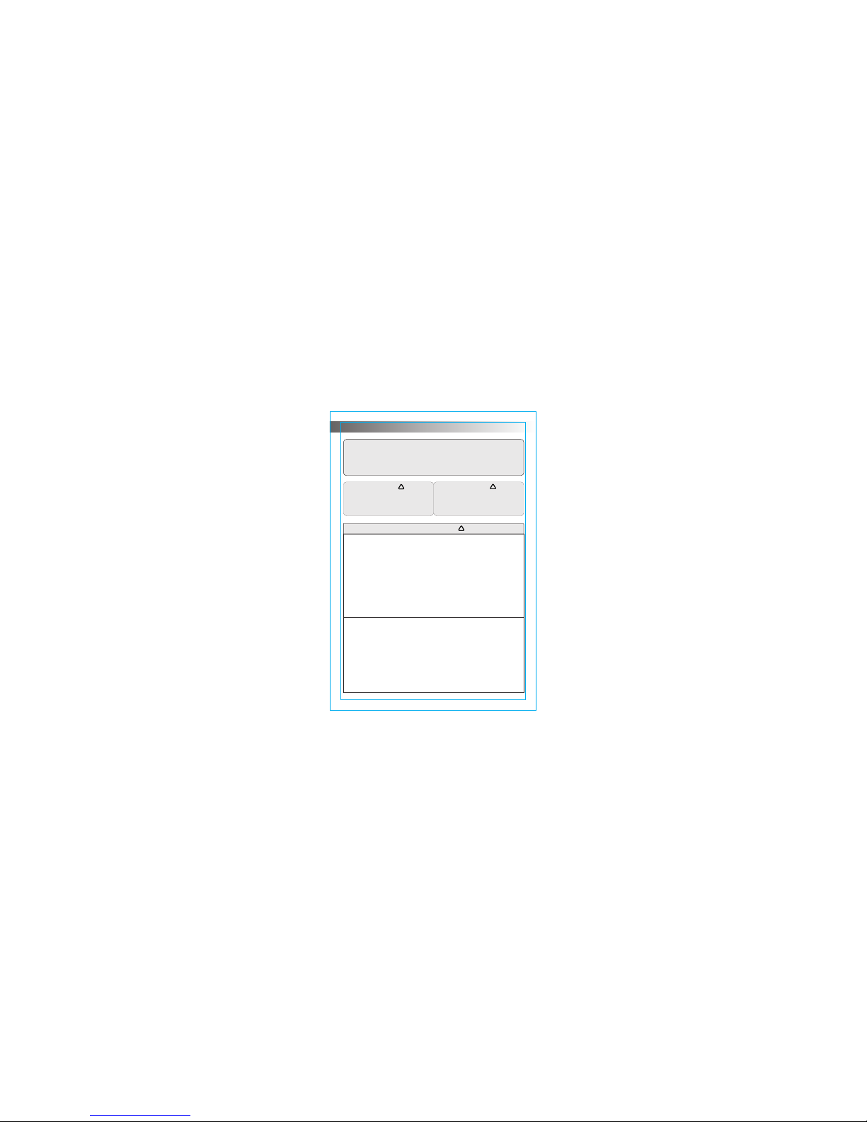
Safety Precautions
Incorrect inst allation or operation by not f ollowing these
instructions m ay cause harm or damage to peopl e,
properties, et c.
The seriousnes s is classified by the followi ng indications:
CAUTION
This symbol indicates the
possibility of injury or
damage to properties.
This symbol indicates
the possibility of death
or serious injury.
WARNING
WARN ING
!
!
!
This appliance c an be used by children aged from 8 y ears
and above and pers ons with reduced physical, s ensory or
mental capabil ities or lack of experience an d knowledge if
they have been giv en supervision or instruct ion concerning
use of the applian ce in a safe way and understand th e
hazards involv ed. Children shall not play wi th the appliance.
Cleaning and use r maintenance shall not be mad e by
children witho ut supervision.
(Only for the AC with CE- MARKING)
This appliance i s not intended for use by person s (including
children) with r educed physical, sensory o r mental
capabilities , or lack of experience and know ledge, unless
they have been giv en supervision or instruct ion concerning
use of the applian ce by a person responsible for t heir safety.
Children shoul d be supervised to ensure that t hey do not
play with the appl iance.
(Except for the AC with C E-MARKING)
- 1 -
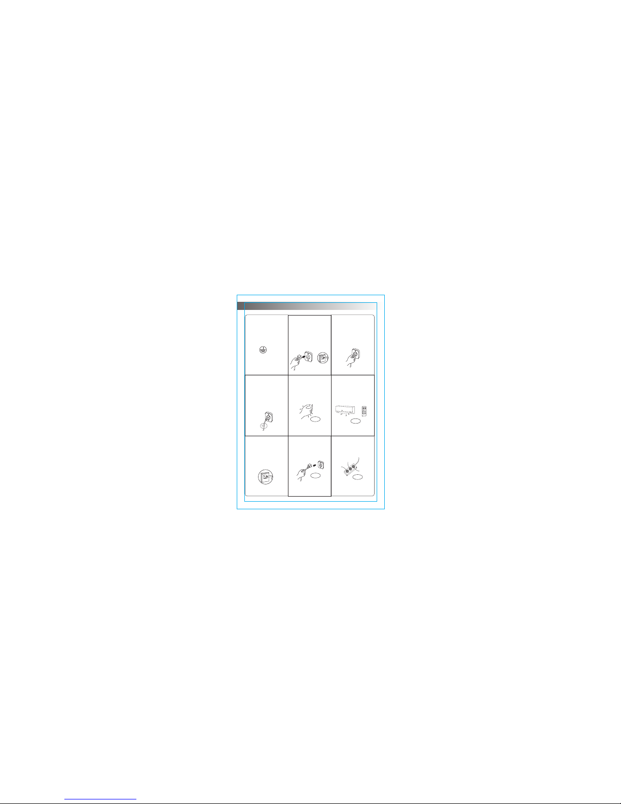
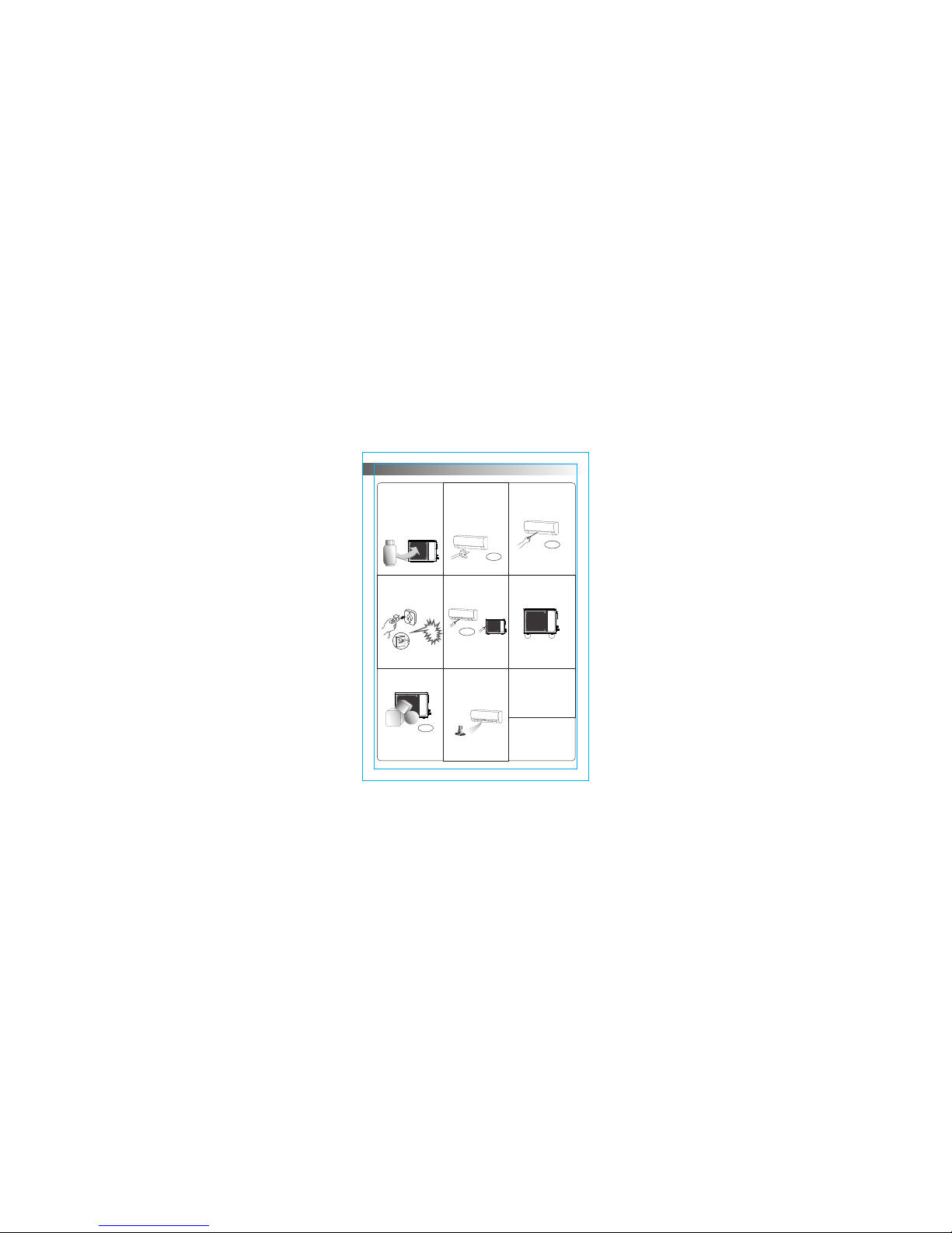
The air conditioner
must be grounded.
Incomplete ground ing may result in
electric shocks.
Do not connect the earth wi re
to the gas pipeline, wate r
pipeline, lightning r od, or
telephone earth wire.
Pull out the plug
(or cut off the main
power switch) when
the unit is not in use
for long time so as
to ensure safety.
Before the connector
is plugged in, please
make sure that there
is no dust on it and
that it is plugged fully
in place.
If the power supply
cord is damaged, it
must be replaced by
the manufacture or
its service agent or
a similar qualified
person.
Don't pull out the
power plug during
operating or with
wet hands.
It may cause electric
shock or fire.
NO!
Take care not let
the remote control
and the indoor unit
watered or being
too wet.
Otherwise, it may cause
short circuit even fire .
SET TEMPERATURE(℃)
自动 自动自动
制冷 制冷制冷
除湿 除湿除湿
制热 制热制热
SET
ON/OFF
MODE
CLEAN
SPEED
SLEEP
HEALTH
STRONG
SWING
DUST
FEELING
FUNGUSPROOF
SCREEN
TIMER
AUTO FAN
COOL HIGH
DRY MID
HEAT LOW
NO!
Don't pull the
power cord when
pull out the power
plug.
The damage of pulling pow er
cord will cause serious e lectric
shock.
NO!
Don't share the
socket with other
electric appliance.
Otherwise, it may cause
electric shock even fir e.
NO!
OF
F
Always switch off
the device and cut
the power supply
before performing
any maintenance
or cleaning.
Otherwise, it may cause
electric shock or damag e.
O
FF
Safety precautions
- 2 -
Don't install air
conditioner in a
place where there is
flammable gas or
liquid. The distance
between them
should above 1m.
It may cause fire.
above 1m
Don't use liquid or
corrosive cleaning
agent wipe the air
conditioner and
sprinkle water or
other liquid either.
NO!
Doing this may case elect ric
shock or damage to the unit .
Don't attempt to
repair the air
conditioner by
yourself.
Incorrect repairs may c ause
electric or fire. Conta ct a
qualified service tec hnician
for all service require ment.
Don't use air
conditioner in
lightning strom
weather.
L
i
g
h
t
n
i
ng
Power supply should be cu t
in time to prevent the
occurrence of danger.
The appliance
shall be installed
in accordance with
national wiring
regulations.
An earth leakage
breaker with rated
capacity must be
installed to avoid
possible electric
shocks.
Don't block air inlet
or air outlet.
Otherwise, the coolin g or
heating capacity will b e
weakened, even cause
system stop operating .
Please note whether
the installed stand is
firm enough or not.
If it is damaged, it may lead
to the fall of the unit and
cause the injury.
NO!
Don't put hands or
any objects into the
air inlets or outlets.
NO!
This may cause personal
injury or damage to the uni t.
OF
F
Don’t let the air
conditioner blow
against the heater
appliance.
Otherwise it will lead to
incomplete combusti on, thus
causing poisoning.
Safety Precautions
NO!
- 3 -

Safety Precautions
This product contains fluorinated greenhouse gases.
WEE E Warnin g
Do not dispose of electrical appliances as
unsorted municipal waste, use separate
collection facilities.
Contact you local government for information
regarding the collection systems available.
If electrical appliances are disposed of in
landfills or dumps, hazardous substances
can leak into the groundwater and get into
the food chain, damaging your health and
well-being.
When replacing old appliances with new ones, the retailer
is legally obligated to take back your old appliance for
disposals at least free of charge.
Meaning of crossed out wheeled dustbin:
- 4 -
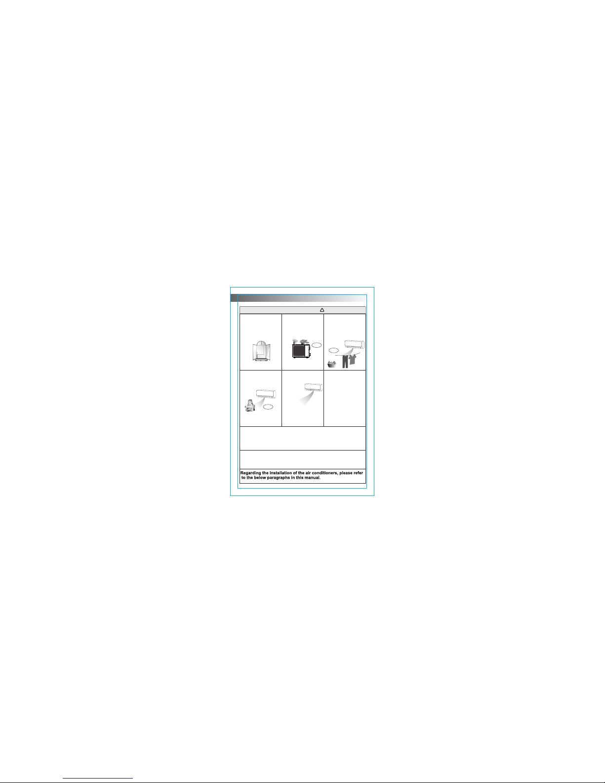
CAU TION
!
Don't apply the cold
air to the body for a
long time.
It will deteriorate your
physical conditions and
cause health problems.
Don’t stand on the
top of the outdoor
unit or place heavy
things on it.
This cloud cause personal
injuries or damage the unit.
Don’t use the air
conditioner for other
purposes, such as
drying clothes,
preserving foods,etc.
NO!
NO!
NO!
Don’t open the
windows and doors
for long time when
the air conditioner
is running.
Otherwise, the cooling or heating
capacity will be weakened.
Set the suitable
temperature.
If your air
conditioner is not
fitted with a supply
cord and a plug, an
all-pole switch must
be installed in the
fixed wiring and the
distance between
contacts should be
no less than 3.0 mm.
The power supply circuit should have leakage protector and air
switch of which the capacity should be more than1.5 times of
the maximum current.
Appropriate adjustments of the
setting temperature can prevent
the waste of electricity.
If your air conditioner is permanently connected to the fixed
wiring, a residual current device (RCD) having rated residual
operating current not exceeding 30 mA should be installed in
the fixed wiring.
It is recommended
that the temperature
difference between
indoor and outdoor
temperature
should not be
too large.
Safety Precautions
- 5 -

Notes for heating
* The fan of the indoor unit will not start running immediately after the heating is
started to avoid blowing out cool air.
* When it is cold and wet outside, the outdoor unit will develop frost over the heat
exchanger which will compromise the heating capacity. This is when the air
conditioner will start defrost.
* During defrost, the air conditioner will stop heating for about 5-12 minutes.
* Vapor may come out from the outdoor unit during defrost. This is not a malfunction,
but a result of fast defrost.
* Heating will resume after defrost is complete.
Notes for turning off
* When the air conditioner is turned off, the main controller will automatically decide
whether to stop immediately or after running for dozens of seconds with lower
frequency and lower air speed.
Notices for use
- 6 -
The conditions of unit can't normally run
* Within the temperature range provided in following table, the air conditioner may
stop running and other anomalies may arise.
* When the temperature is too high, the air conditioner may activate the automatic
protection device, so that the air conditioner could be shut down.
* When the temperature is too low, the heat exchanger of the air conditioner may
freeze, leading to water leakage or other malfunction.
* In long-term cooling or dehumidification with a relative humidity of above 80%
(doors and windows are open), there may be water condenses or dripping near
the air outlet.
* T1 and T3 refer to ISO 5151.
Cool ing
Heat ing
Indo or
Outd oor
Indo or
Outd oor
<18℃
>24℃
<-7℃
>27℃
>52℃(Apply to T3 )
>43℃(Apply to T1 )
* If the remote controller is lost or broken,
use force switch button to operate the
air conditioner.
* If this button is pushed with the unit OFF,
the air conditioner will operate in Auto mode.
* If this button is pushed with the unit ON,
the air conditioner will stop running.
Emergency operation
1. Use up-down swing and left-right swing
buttons on the remote controller to adjust
the airflow direction. Refer to the operation
manual of the remote controller for detail.
2. For models without left-right swing function,
the fins has to be moved manually.
Force switch
Airflow direction adjustment
Note: Move the fins before the unit is in operation,
or your finger might be injured.
Never place your hand into the air inlet or
outlet when the air conditioner is in operation.
- 7 -
Notices for use
ATTENTION
If the equipment emissions cannot meet the technical requirement of IEC 61000-3-3,
following Attention should be take care.
Attention:This appliance can be connected only to a supply with system impedance
no more than Zmax. In case necessary, please consult your supply authority for system
impedance information.
Product Type
Zmax
Product Type
Zmax
ASTW-H 12L4/ #-IQ
0.445
ASTW-2 4G4/# -AE
0.027
ASTW-1 2U4/# -AE
ASTW-1 8U4/# -AE
ASTW-H 18U4/ #-IQ
ASTW-H 24C4/ #-IQ
0.445
0.128
0.128
0.027
ASTW-( H)18Q A2/#R 1-SA
ASTW-3 0P4/# -AE
ASTW-2 0U4/L #-IR
ASW-H1 5D3A4 /#R1- C5
0.331
0.026
0.07
0.392
ASW-H1 8E1A4 /#R1- C5
0.422
ASW-H2 4F6A4 /#R1- C5
0.281
#=LK700,LF,LH,LI,LM,LN,LR,LU,LS,LD,LP, LQ,LB,LO,LC,LE,LL,ULK700,ULF,ULH,ULM,ULN,ULI,ULS,ULU,ULD,ULP,ULR,
ULQ,ULB,ULO,ULC,ULE,ULL,QLK700,QLF,QLH,QLM,QLN,QLI,QLS,QLU,QLD,QLP,QLR,QLQ,QLB,QLO,QLC,QLE,
QLLGLK700,GLF,GLH,GLM,GLN,GLI,GLS,GLU,GLD,GLP,GLR,G LQ,GLB,GLO,GLC,GLE,GLL
ASW-H1 8E1A4 /#R1- RU
0.421
ASW-H2 4B4/# R1-RU
0.315
ASTW-1 8Q4/# -AE
0.112
#= FA,FB,FD,FI,FJ,FO,FC,FY,FQ,FM,FF,FH,FVMA
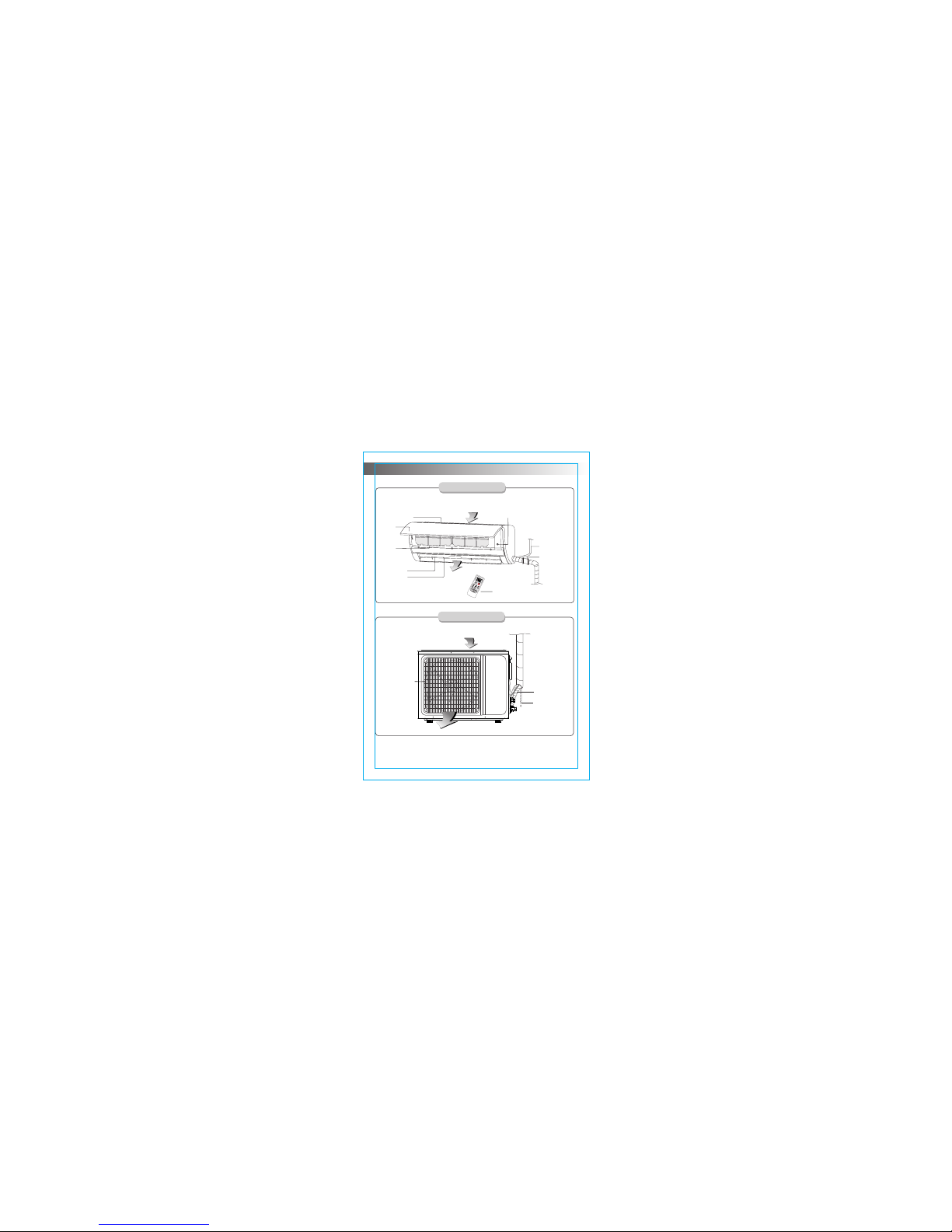
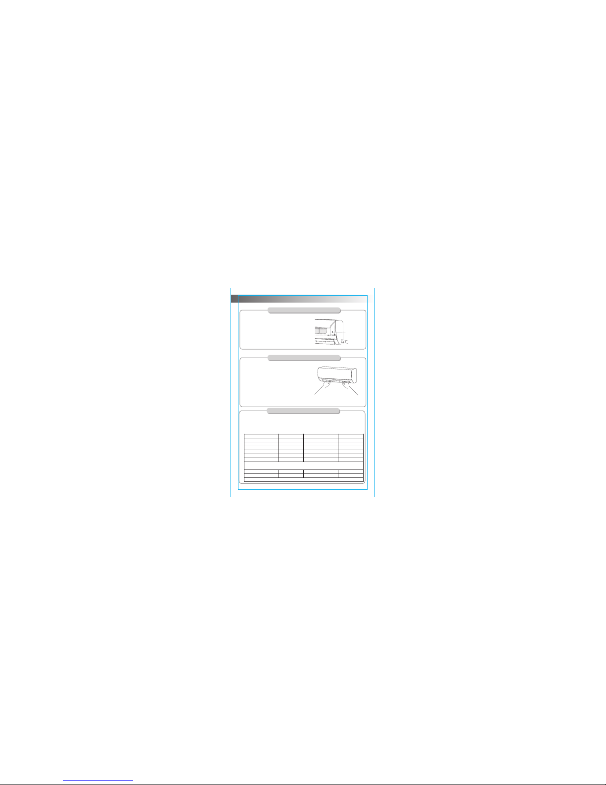
iFEEL
Force switch
Power cord
Pipe protection
ring
Air inlet
Ind oor uni t
Panel
Air inlet grille
Air filter
Air louver
Air vent
Air outlet
Connecting pipe
Drain hose
Air inlet
Air outlet
Air ou tlet gr ille
Out door un it
Remoter controller
Note: All the pictures in this manual are just schematic diagrams,
the actual is the standard.
Names of each part
- 8 -

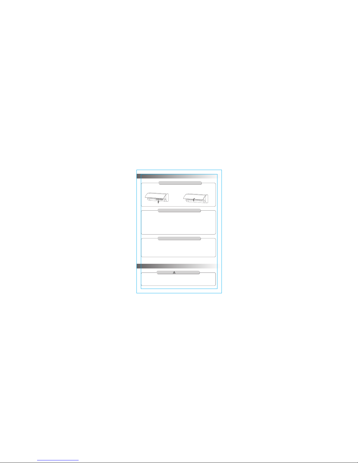
Clean the panel
When the panel of the indoor unit is contaminated, clean it
gently with a wrung towel using tepid water below 45℃,
and do not remove the panel while cleaning.
Clean the air filter
■ Remove the air filter
1. Use both hands to open the panel for an angle from both ends of the panel in
accordance with the direction of the arrow.
2. Release the air filter from the slot and remove it.
● Before the cleaning of the air conditioner, it must be shut down and the
electricity must be cut off for more than 5 minutes, otherwise there might
be the risk of electric shocks.
● Do not wet the air conditioner, which can cause an electric shock. Make
sure not to rinse the air conditioner with water under any circumstances.
● Volatile liquids such as thinner or gasoline will damage the air conditioner
housing, therefore please clean the housing of air conditioner only with soft
dry cloth and damp cloth moistened with neutral detergent.
● In the course of the using, pay attention to cleaning the filter regularly, to
prevent the covering of dust which may affect the effect. If the service
environment of the air conditioner is dusty, correspondingly increase the
number of times of cleaning. After removing the filter, do not touch the fin
part of the indoor unit with the finger, so as to avoid scratching it.
Warning
■ Clean the Air Filter
Use a vacuum cleaner or water to rinse filter, and
if the filter is very dirty (for example, with greasy dirt),
clean it with warm water (below 45℃) with mild
detergent dissolved in, and then put the filter in
the shade to dry in the air.
Clean and care
- 9 -
■ Mount the F ilter
1. Check whether all the air inlets and outlets of the units are unblocked.
2. Check whether there is blocking in the water outlet of the drain pipe, and
immediately clean it up if any.
3. Check the ground wire is reliably grounded.
4. Check whether the remote control batteries are installed, and whether the power
is sufficient.
5. Check whether there is damage in the mounting bracket of the outdoor unit, and
if any, please contact our local service center.
Check before use
1. Reinstall t he dried filte r in reverse ord er of removal, t hen cover and lo ck the panel.
Clean and care
* Do not repair the air conditioner by yourself as wrong maintenance may cause electric
shock or fire, please contact the authorized service center and let the professionals
conduct the maintenance, and checking the following items prior to contacting for
maintenance can save your time and money.
Caution
Troubleshooting
Maintain after use
1. Cut off the power source of the air conditioner, turn off the circuit breaker and remove
the batteries from the remote control.
2. Clean the filter and the unit body.
3. Remove the dust and debris from the outdoor unit.
4. Check whether there is damage in the mounting bracket of the outdoor unit, and if
any, please contact our local service center.
- 10 -
Clean the air filter

Remote controller
is not available.
● Is the remote controller out of effective distance to the indoor unit?
● Are there any obstructions between the controller and the
signal receptor? ● Is the battery exhausted?
Indoor unit does not operate
immediately when the air
conditioner is restarted.
There is unusual smell
blowing from the outlet
after operation is started.
Cooling (Heating)
efficiency is not
good.
● Is the setting temperature suitable? ● Are air filter dirty?
● Is the air inlet or outlet obstructed?
● Is indoor fan speed set at low speed?
● Is there any heat source in your room?
Air conditioner can
not operate at all.
● Has the power been shut down? ● Is the wiring loose?
● Is voltage too high or too low ?(measured by professionals)
● Does it reach the set time for start up?
● Does the circuit protection device trip?
If the air conditioner is turned on immediately after it is
turned off, the protective delay switch will delay the
operation for 3 to 5 minutes.
The air conditioner itself does not have undesirable
odor. If there is odor, it may be due to accumulation
of the odor in the environment. Please clean the air
filter or activate the cleaning function.
There is sound of running
water during the running
of air conditioner.
Sometimes the "hissing" sound of running water
can be heard. This is the sound of the flow of the
refrigerant, not a malfunction.
A slight "click" sound is
heard at the of start-up or
shut-down.
Due to temperature changes, panel and other parts
will swell, causing the sound of friction. This is normal,
not a fault.
During the cooling operation,
the indoor unit outlet
sometimes will blow out mist.
This is because the indoor air is cooled rapidly. After it
runs for some time, the indoor temperature and
humidity will be reduced and the mist will disappear.
▲ Shrill sound is heard or Unpleasant odor is emitted during the operation.
▲There is an abnormal heat in power supply cord and power plug.
▲ Accidentally pour impurities or water into the machine or the remote control.
▲ Air switch or protection switch often breaks.
Immediately stop all operations and cut off the power supply ,
contact our Service center locally in following situations.
Troubleshooting
Phe nomen on
Troubleshooting
- 11 -

Important Notices
■ Before installating, please contact with local authorized
maintenance center, if unit is not installed by the authorized
maintenance center, the malfunction may not solved,due to
discommodious contact.
■ The air conditioner must be installed by professionals according
to the national wiring rules and this manual.
■ To move and install air conditioner to another place, please
contact our local special service center.
Requirements For Installation Position
● Avoid places of inflammable or explosive gas leakage or where
there are strongly aggressive gases.
● Avoid places subject to strong artificial electric/magnetic fields.
● Avoid places subject to noise and resonance.
● Avoid severe natural conditions (e.g. heavy lampblack, strong
sandy wind, direct sunshine or high temperature heat sources).
● Avoid places within the reach of children.
● Shorten the connection between the indoor and outdoor units.
● Select where it is easy to perform service and repair and
where the ventilation good.
● The outdoor unit shall not be installed in any way that could
occupy an aisle, stairway, exit, fire escape, catwalk or any other
public area.
● The outdoor unit shall be installed as far as possible from the
doors and windows of the neighbors as well as the green plants.
Requirements for operations at raised height
● When carrying out installation at 2m or higher above the base
level, safety belts must be worn and ropes of sufficient strength
be securely fasten to the outdoor unit, to prevent falling that
could cause personal injury or death as well as property loss.
Notices for installation
- 12 -

Electrical Safety Requirements
● Be sure to use the rated voltage and air conditioners dedicated
circuit for the power supply, and the power cord diameter must
meet the national requirements.
● When the maximum current of air conditioner is ≥16A, it must use
the air switch or leakage protection switch equipped with
protection devices.
● The normal operating range is 90%-110% of the local rated voltage.
● The minimum clearance between the air conditioner and the
combustibles is 1.5 m.
● The air conditioner is the type I electrical appliance and must
ensure a reliable grounding.
● Do not connect the grounding wire to a gas pipe, water pipe,
lightning rod, telephone line, or a circuit poorly grounded to
the earth.
● The grounding wire is specially designed and shall not be used
for other purpose, nor shall it be fastened with a common
tapping screw.
Grounding Requirements
Requirements of the mounting structure
● The mounting rack must meet the relevant national or industrial
standards in terms of strength with welding and connection
areas rustproofed.
● The mounting rack and its load carry surface shall be able to
withstand 4 times or above the weight of the unit, or 200kg,
whichever is heavier.
● The mounting rack of the outdoor unit shall be fastened with
expansion bolt.
● Ensure the secure installation regardless of what type of wall
on which it is installed, to prevent potential dropping that could
hurt people.
Notices for installation
- 13 -

● The connection method of the air conditioner and the power cord
and the interconnection method of each independent element
shall be subject to the wiring diagram affixed to the machine.
● The model and rating value of the fuse shall be subject to the
silkscreen on corresponding controller or fuse sleeve.
Others
PC
Drai n pipe
1
5
Plas tic Str ap
Pipe P rotec tion Ri ng
Luti ng (put ty)
NOTE: All accessories shall be subject to actual packaging material, and if there
is any difference, please understand.
Packing list of the indoor unit
Packing list of the outdoor unit
N0.
Name
1
2
3
1
Indo or Unit
Set
Quan tity
2
Remo te Cont rolle r
Batt eries (7#)
PC
PC
1
Inst ructi ons
4
Outd oor Uni t
Conn ectin g pipe
Packing list
1
Notices for installation
5
N0.
Name
1
2
3
ROLL
4
Unit
PC
1
1
1
Set
Quan tity
PC
1
2
Unit
- 14 -
PACKE T
Set

1. Make a hole with an electric hammer or a
water drill at the predetermined position on
the wall for piping, which shall slant outwardly
by 5°-10°.
2. To protect the piping and the cables from
being damaged running through the wall,
and from the rodents that may inhabit in
the hollow wall, a pipe protecting ring shall
be installed and sealed with putty.
1. The wall for installation of the indoor unit shall
be hard and firm, so as to prevent vibration.
2. Use the "+" type screw to fasten the peg board,
horizontally mount the peg board on the wall, and
ensure the lateral horizontal and longitudinal vertical.
3. Pull the peg board by hand after the installation,
to confirm whether it is solid.
Space to the ceiling
Space to the wall
20cm abov e
Mounting plate
Wall-through Hole
15cm abov e
200cm abo ve
Space to the floor
Pipe protection ring
Putty
Dimension drawing of indoor unit installation
Space to the wall
20cm abov e
Note: Usually, the wall hole is Φ60mm~Φ80mm.
Avoid pre-buried power wire and hard wall
when making the hole.
- 15 -
Install indoor unit

1. Depending on the position of the unit, the piping may be routed sideway from the
left or the right ( Fig 1 ), or vertically from the back( Fig 2 )(depending on the pipe
length of the indoor unit). In the case of sideway routing, cut off the outlet cutting
stock of the opposite side.
2. The power cord may be routed separately from the piping. Cut off the outlet cutting
stock and then run the power cord through the hole, keeping the remaining part as
a protection from rodents.
Route of Pipeline
Connecting Pipe
Drain Hose
and Cables
Connecting Pipe
Drain Hose
and Cables
Power cord
Φ6/Φ6.35
Φ9.5 2
Φ12/Φ12.7
Φ15. 88
Φ19. 05
75~80
Tightening torque table
The size of pipe(mm)
Torque(N·m)
1. Remove the mountings and pull the indoor unit pipe out of the housing.
2. Connect the connecting pipe to the indoor unit:
Aim at the pipe center, tighten the Taper nut with fingers, and then tighten the Taper
nut with a torque wrench, and the direction
is shown in diagram on the right. The torque
used is shown in the following table.
Drain pipe connection
Spanner
Indoor unit pipe
Taper nut
Torque wrench
connecting pipe
Wrap the Piping
1. Use the insulation sleeve to wrap the joint part
the indoor unit and the connection pipe, and then
use insulating material to pack and seal insulation
pipe, to prevent generation of condensate water on
the joint part.
2. Connect the water outlet with drain pipes, and make
the connection pipe, cables, and the drain hose straight.
3. Use plastic cable ties to wrap the connecting pipes, cables
and drain hose. Run the pipe sloping downward.
Connecting Pipe
Drain Hose
and Cables
Plastic Strap
Fig 1
Fig 2
Install indoor unit
- 16 -
Hole material preparation
Outlet material preparation

Fixing the Indoor Unit
1. Hang the indoor unit on the peg board,
and move the unit from left to right to
ensure that the hook is properly positioned
in the peg board.
2. Push toward the lower left side and the
upper right side of the unit toward the peg
board, until the hook is embedded in the
slot and makes a "click" sound.
Wiring diagram
● If your air conditioner is provided with power cable, the wiring of the indoor
unit is connected in the factory, there is no need of connection.
● If the power cable is not provided, connection is needed in accordance with
the wiring diagram.
Connecto r
If there is a connector,
connect it directly.
To Outdoor u nit
1
2(N)
To Outdoor u nit
4
1(L)
5
3
2(N)
To Outdoor u nit
4
1(L)
5
3
2(N)
To Outdoor u nit
1
2(N)
4
5
constant speed
Heat-pump type
To Outdoor u nit
L
N
S
Variable speed
Cooling Only
Install Indoor Unit
NOTE:
※ This manual is usually includes the wiring mode for the different kind of A/C.
We cannot exclude the possibility that some special type of wiring diagrams
are not included.
※ The diagram are for reference only. If the entity is difference with this wiring
diagram, please refer to the detailed wiring diagram adhered on the unit which
you purchased.
- 17 -

A
Left ins talla tion fe et
Right in stall ation f eet
Air inle t
H
W1
B
D
Air outl et
W2
Dimension drawing of outdoor unit installation
20cm Above
Space to the obstruction
10cm Above
Air in side
30cm Above
Space to the obstruction
200cm Above
Air out side
30cm Above
Connect the Outdoor Unit with Connecting Pipe:
Aim the counter-bore of the connecting pipe at the
stop valve, and tighten the Taper nut with fingers.
Then tighten the Taper nut with a torque wrench.
Stop valve
Spanner
Gas side pipe
liquid side pipe
Connecting pipe
Taper nut
Install the connection pipe
When prolonging the piping, extra amount of refrigerant
must be added so that the operation and performance
of the air conditioner will not be compromised.
Not nee ded
≤5M
Piping length
Amount of refrigerant to be added
5-15 M
CC≤1200 0Btu
CC≥1800 0Btu
20g/ m
30g/ m
Note: This table is for reference only.
665(7 10)×4 20×28 0 430 280
Outdoor Unit Size of Shape
W1(W2)*H*D) (mm)
A (mm) B (mm)
Inst allat ion out door un it bolt
600(6 45)×4 85×26 0
400
290
660(7 10)×5 00×24 0
500
260
700(7 45)×5 00×25 5
460
260
730(7 80)×5 45×28 5
540 280
760(8 10)×5 45×28 5
540
280
800(8 60)×5 45×31 5
545
315
800(8 50)×5 90(69 0)×31 0
540 325
825(8 80)×6 55×31 0
540
335
900(9 50)×7 00×35 0
630
350
900(9 50)×7 95×33 0
535
350
790(8 40)×5 50×29 0
545
300
Install outdoor unit
- 18 -
Space to the obstruction

1.Loosen the screws and remove E-parts cover from the unit.
2.Connect the cables respectively to the corresponding terminals
of the terminal board of the outdoor unit (see the wiring diagram),
and if there are signals connected to the plug, just conduct butt joint.
3.Ground wire: Remove the grounding screw out of the electric
bracket, cover the grounding wire end onto the grounding screw
and screw it into the grounding hole.
4.Fix the cable reliably with fasteners (Pressing board).
5.Put the E-parts cover back in its original place and fasten
it with screws.
E parts cover-
1
2
L
N
Wiring Connection
Wiring diagram
Connecto r
If there is a connector,
connect it directly.
constant speed
Heat-pump type
Variable speed
Cooling Only
1
2(N)
1
2
3
To Indoo r unit
To Indoo r unit
1
2(N)
4
5
To Indoo r unit
534
1
2
To Indoo r unit
To Indoo r unit
1(L)
2(N)
4(S)
NOTE:
※ This manual is usually includes the wiring mode for the different kind of A/C.
We cannot exclude the possibility that some special type of wiring diagrams
are not included.
※ The diagram are for reference only. If the entity is difference with this wiring
diagram, please refer to the detailed wiring diagram adhered on the unit which
you purchased.
Install outdoor unit
- 19 -
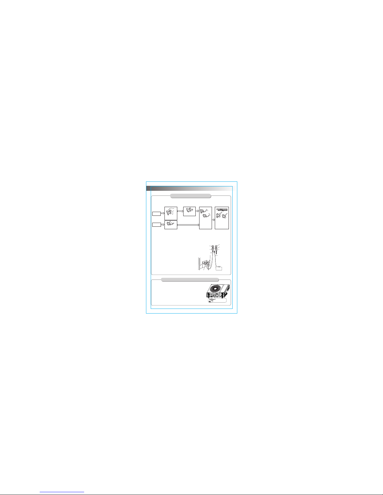
Expelling the air
After the pipe side conn ection is complete, proce ed as follows.
★Outdoor unit refri gerant discharging metho d
Quickly tighten and
connect the nut.
The installing torque
is the same as that
of the gas end of
the indoor unit.
Fully open the
spindles of the
liquid end and of
the other two ends.
Check that all indoor
and outdoor
connections are free
of air leakage.
Wait for
8 second
Loosen the
temporarily fastened
nut by half turn.
Loosen the Hex
wrench by half turn.
Gas part
Liquid part
Before working on the air conditioner, remove the cover of the stop valve(gas and
liquid valves)and be sure to retighten it afterward.(to prevent the potential air leakage)
1. To prevent air leakage and spilling tighten
all connecting nut of all flare tubes.
2. Connect the stop valve, charge hose, manifold
valve, and vacuum pump.
3. Fully open the handle Lo of the manifold valve
and apply vacuum for at least 15 minutes and
check that the compound vacuum gauge reads
-0.1MPa(-76cmHg).
4. After applying vacuum, fully open the stop
valve with a hex wrench.
5. Check that both indoor and outdoor
connections are free of air leakage.
Pressure gauge
Charge hose
-76cmHg
manifold valve
Compound meter
Handle Hi
Handle Lo
Vacuum pump
(liquid valve)
(gas valve)
Stop valve
Stop valve
When the unit is heating, the condensing water and defrosting
water can be out reliably through the drain house.
Installation:
Install the outdoor drain elbow in Φ25 hole on the base
plate, and joint the drain hose to the elbow, so that the
waste water formed in the outdoor unit can be drained
out to a proper plate.
Chassis
Outdoor drain elbow
Outdoor condensation drainage(Heat pump type only)
★Vacuum Pumping Method (R410A refrigerant evacuation must use the vacuum
pumping method)
Charge hose
Install outdoor unit
- 20 -

Test Operation preparation
※V erify that all piping and connection cables are well connected.
※C onfirm that the values at the gas side the liquid-side are fully open.
※C onnect the power cord to an independent power socket.
※I nstall batteries in remote control.
Test Operation method
1. Turn on the power and push the ON/OFF switch button of the remote controller to
start the air conditioner.
2. Select COOL, HEAT (not available on cool-only models), SWING and other
operation modes with the remote controller and see if the operation is ok.
Check after installation and test operation
Check after installation
Test Operation
★ Electrical Safety Check
1. If the supply voltage is as required.
2. If there is any faulty or miss connection in each of the power, signal and
grounding wires.
3. If the grounding wire of the air conditioner is securely grounded.
★ Installation Safety Check
1. If the installation is secure.
2. If the water drain is smooth.
3. If the wiring and piping are correctly installed.
4. Check that no foreign matter or tools are left inside the unit.
★ Leak test of the refrigerant
Depending on the installation method, the following methods may be used to check
for suspect leak, on areas such as the four connections of the outdoor unit and the
cores of the cut-off valves and t-valves:
1.Bubble method: Apply of spray a uniform layer of soap water over the suspected
leak spot and observe carefully for bubble.
2.Instrument method: Checking for leak by pointing the probe of the leak detector
according to the instruction to the suspect points of leak.
- 21 -
Air Co nditi oner Co ntain s fluor inate d green house g ases co vered b y the
Kyoto P rotoc ol. GWP :2088

SET TEMPERATURE(℃)
自动 自动自动
制冷 制冷制冷
除湿 除湿除湿
制热 制热制热
SET
ON/OFF
MODE
CLEAN
SPEED
SLEEP
HEALTH
STRONG
SWING
DUST
FEELING
FUNGUSPROOF
SCREEN
TIMER
AUTO FAN
COOL HIGH
DRY MID
HEAT LOW
AIR -COND ITION ER REMO TE
CON TROLL ER INST RUCTI ONS
● Read t his “ins truct ions” ca reful ly so tha t
you ca n use the a ir-co nditi oner sa fely an d
corr ectly.
● Take goo d care of t he “inst ructi ons” so
that i t can be re ferre d to at any t ime.

Usag e---- ----- ----- ----- ----- ----- ----- ----- ----- ----- ----- ---
Fix ba tteri es ---- ----- ----- ----- ----- ----- ----- ----- ----- --
Nigh t Lumin ous Fun ction o f Remot e Contr oller - ---
Auto matic o perat ion mod e---- ----- ----- ----- ----- ----- -
Atte ntion - ----- ----- ----- ----- ----- ----- ----- ----- ----- ----- --
Butt ons des cript ion-- ----- ----- ----- ----- ----- ----- ----- ----
1
5
6
7
CON TENTS
Cool ing/H eatin g opera tion mo de--- ----- ----- ----- ----
5
5
5
Fan op erati on mode ----- ----- ----- ----- ----- ----- ----- ---
Dryi ng oper ation m ode-- ----- ----- ----- ----- ----- ----- --
6
6

But tons de scrip tion
SET TEMPERATURE(℃)
自动 自动自动
制冷 制冷制冷
除湿 除湿除湿
制热 制热制热
SET
ON/OFF
MODE
CLEAN
SPEED
SLEEP
STRONG
SWING
FEELING
DUST
FUNGUSPROOF
SCREEN
TIMER
AUTO FAN
COOL HIGH
DRY MID
HEAT LOW
1
8
10
12
2
3
4
5
6
7
14
13
11
9
1.“ON/ OFF” but ton
You can st art or st op the ai r-con ditio ner by pr essin g this
butt on.
2.“SPE ED” butt on
You can se lect fa n speed a s the fol lowin g:
High
Low
Auto
Mid
FEELING
TIMER
SPEED
TRANSMIT
ON/OFF
ROOM
SET
TIMER ON OFF
DIGITAL
RUNNING
MODE
RUNNING
MODE
LCD di splay i nstru ction
ON/O FF disp lay:
when t he remo te cont rolle r is
on the s tate, t he LCD wi ll be
disp lay or no t.
Digi tal dis play:
Unde r the sta te of nor mal
work ing, it d ispla ys sett ing
temp eratu re. Whi le the fe eling
func tion is s tart, i t will di splay
room t emper ature , and und er
the st ate of ti mer mod e, it wil l
disp lay set ting ti mer.
3.“STR ONG”but ton
Only u nder th e state o f cooli ng or hea ting mo de, pre ss this
butt on, the f an spee d is adju sted to s trong a uto-m aticl ly
and th e LCD dis plays high f an , the stro ng fun ction “ ” “ ”
is sta rted to r each th e highe st cool ing or he ating .
Note: Th e pictur e is genera l remote co ntroll er, contai ns
almost a ll of the fu nction bu ttons. Th ey may be sl ightly
differ ent from m aterial a bject(d epend on m odel).
HEALTH
The cooling on ly units don't h ave the functi on of heating or e lectric
heating. Whe n the remote con troller turn s to such functi on buttons,
the units will n ot result such e ffect.
*Please don' t turn the remot e controller t o such buttons .

2
Pres s this bu tton ca n be used t o set the f eelin g funct ion.
The LC D shows t he actu al room t emper ature w hen the
func tion se t and it sh ows the s ettin g tempe ratur e when th e
func tion ca ncell ed. This f uncti on is inv alid wh en the
appl iance a t the Fan m ode.
4.“FEE LING” bu tton
5.“HEA LTH” butto n
When i t displ ays “FEE LING” bu tton:
6.“TIM ER” butt on
Sett ing the “O N” timer t ime:
“ ”a. Whe n remot e contr oller i s at off sta te, pre ss TIM ER
butt on, the L CD disp lays T IMER ON and th e timer “ ”
time , the ran ge of set ting ti me is 0.5 h to 24h.
b. You can p ress th e or butt on to adj ust the “ ” “ ”
time r time, e ach tou ch will b e set tim e to incr ease or
redu ce 0.5h b efore 1 0 hours a go, aft er ten ho urs wil l be
set ti me to inc rease o r reduc e 1h per pr essin g, to ena bles
your r equir ed time r.
c. Pre ss TIM ER but ton aga in, to se t the tim er on fun ction .“ ”
d. You can s et anot her fun ction t o insur e the sui table s tate
afte r air con ditio ner tur n on (inc ludin g mode, t emper ature ,
swin g, fan sp eed and e tc). The L CD will d ispla ys all yo ur
sett ing and k eep it, w hen the t imer re ach to th e set tim e,
the ai r condi tione r will be w orkin g accor ding to y our set
auto matic ally.
Sett ing the “O FF” time r time:
“ ”a. Whe n remot e contr oller i s at on sta te, pre ss TIM ER
butt on, the L CD disp lays T IMER OF F and th e timer “ ”
time , the ran ge of set ting ti me is 0.5 h to 24h.
b. You can p ress th e or butt on to adj ust the “ ” “ ”
time r time, e ach tou ch will b e set tim e to incr ease or
redu ce 0.5h b efore 1 0 hours a go, aft er ten ho urs wil l be
set ti me to inc rease o r reduc e 1h per pr essin g, to ena ble
your r equir ed time r.
c. Pre ss TIM ER but ton aga in, to se t the tim er off fun ction .“ ”
7.“SCR EEN” but ton
You can le t the LCD d ispla y worki ng or not b y press ing thi s
butt on.
△
△
△
△
You can st art or st op “HEALT H” funct ion by pr essin g this
butt on. Acco rding t o envir onmen t tempe ratur e, the ai r
cond ition er can ru n intel ligen tly, and ch oose sp eed
auto -mati cly. It can c reate a c omfor table s urrou nding s
auto -mati cly to ge t the mos t suita ble tem perat ure for b ody.

3
Pres s the “+”or “-”bu tton, you can s et the te mpera ture
rang e from ℃ ℃16 to 3 2 ,Dis play wi ll chan ge when y ou touc h
the bu tton.
8.“ ”or “ ” bu tton
△
△
9.“CLE AN” butt on
a. Whe n remot e contr oller i s at the off s tate, p ress c lean“ ”
butt on, the w ind gui ding ba rs turn t o initi al post ions fo r
cool ing, th e A/C runs clea n func tion wi th max du ratio n “ ”
35mi ns.Th e purpo se of thi s funct ion is to c lean du st on
evap orato r and dry t he insi de wate r of evap orato r and
to pre vent th e evapo rator g oing mo ldy due t o water
depo sitio n and boa sting s trang e smell .
b. Afte r setti ng cle an fun ction , press clea n butt on “ ” “ ”
agai n to canc el cle an fun ction o r press ON/O FF“ ” “ ”
butt on to can cel cl ean fu nctio n and sta rt A/C.“ ”
c. The cl ean fun ction w ill be st op work ing aft er 35 min utes
runn ing wor king wi thout a ny oper ation .
Note : clea n func tion ca n be set in p arall el with “ ”
tim e start func tion; i n this ca se , tim e start“ ” “ ”
func tion wi ll be exe cuted a fter c lean f uncti on.“ ”
10.“MO DE” butt on
AUTO→CO OL→DRY→HE AT→FAN→AUTO
Rema rk: col d wind ty pe has no h eatin g funct ion.
Whic h enabl es you to s elect d iffere nt oper ation m ode,
afte r each pr essin g, the op erati on mode w ill be ch anged . It
show s in the fo llowi ng disp lay.
11.“SLEE P” butt on
1.Pr ess the S LEEP but ton, th e sleep ing ind icato r light o f
indo or unit f lashe s on.
2.Af ter the s ettin g of slee ping mo de, the c oolin g opera tion
enab les the s et temp eratu re to inc rease 1℃ a fter 1h our
and an other 1℃ a utoma tical ly afte r 1 hour.
3.Af ter the s ettin g of slee ping mo de, the h eatin g opera tion
enab les the s et temp eratu re to dro p 2℃ after 1 hour an d
anot her 2℃ aut omati cally a fter 1 ho ur.
4.Th e air-c ondit ioner r uns in sl eepin g mode fo r 7 hours a nd
stop s autom atica lly.
Rema rk: pre ss the MO DE or ON/ OFF but ton, th e remot e
cont rolle r clear s sleep ing mod e away.

4
12.“SW ING” but ton
Pres s this bu tton, t he hori zonta l wind di recti on vane s can
swin g autom atica lly, when y ou have t he desi red ver tical
wind d irect ion, pr ess it ag ain, th e horiz ontal w ind dir ectio n
vane s will be s toppe d at the si tuati on of you r choic e.
13.“DU ST” butt on
This b utton i s inval id.
14.“FU NGUSP ROOF” bu tton
This A/C h as spec ial dry a nd anti -mold f uncti on whic h
has y es two sel ectio ns. This f uncti on is “ ”or“no”
cont rolle d by the re mote co ntrol ler und er cool ing, dr y and
auto ( cooli ng and dr y) mode s, the ho rizon tal win d guidi ng
bars a re at the i nitia l posit ion for c oolin g. The A/C ru ns
unde r heati ng mode (the co oling o nly A/C on ly runs u nder
fan mo de), th e inter nal fan r uns for t hree mi nutes w ith wea k
wind b efore s top. The p urpos e of this f uncti on is to dr y the
insi de of the e vapor ator an d to prev ent the e vapor ator fr om
goin g mould y due to wa ter dep ositi on and th us disp ersin g
stra nge sme ll.
Note :
1. This f uncti on has no t been se t in the fa ctory. You m ay
free ly set an d cance l this fu nctio n. The se tting m ethod
is: un der of f stat us of the A/ C and the r emote “ ”
cont rolle r, point t he remo te cont rolle r towar d the A/C
and co ntinu ously p ress push butto n “FUN GUSPR OOF”
for on e time, t he buzz er keep b eepin g five ti mes aga in
afte r five ti mes bee p, indi catin g that th is func tion is
read y. In case th is func tion ha s been se t, unle ss the
whol e A/C is pow ered of f or the fu nctio n is manu ally
canc elled , the A/C th en has th is func tion as d efaul t;
2. To cance l the fun ction : 1. Powe r off the w hole A/ C; 2.
Unde r off s tatus o f the A/C an d the rem ote “ ”
cont rolle r, point t he remo te cont rolle r towar d the A/C
and co ntinu ously p ress push butto n “FUN GUSPR OOF”
for on e time, t he buzz er keep b eepin g three t imes ag ain
afte r five ti mes bee p, indi catin g that th is func tion ha s
been c ancel led;
3. When t his fun ction i s on, it is s ugges ted not t o resta rt
the A/C b efore i t is comp letel y stop;
4. This f uncti on will n ot run in c ase of ti me stop o r sleep
stop .

5
Fix ba tteri es
1.Sl ide ope n the cov er acco rding t he dire ction i ndica ted
by arr owhea d.
2.Pu t into tw o brand n ew batt eries ( 7#), po sitio n the
batt eries t o right e lectr ic pole s (+&-).
3.Pu t back th e cover.
Auto matic o perat ion mod e
1.Pr ess the M ODE but ton, se lect th e autom atic op erati on
mode .
2.Pr ess the S PEED bu tton, y ou can se lect fa n speed .
You can se lect fa n speed f rom LOW, M ID, HIG H, AUTO.
3.Pr ess the O N/OFF b utton , the ope ratio n indic ator is o n,
the ai r-con ditio ner sta rts to op erate t he auto matic m ode.
Pres s the but ton aga in, the a ir-co nditi oner st ops.
Cool ing/H eatin g opera tion mo de
(col d wind ty pe has no h eatin g funct ion)
△
△
1.Pr ess the M ODE but ton, se lect th e Cooli ng or Hea ting
oper ation m ode.
2.Pr ess the or butt on, set t he temp eratu re, “ ” “ ”
temp eratu re can be s et at 1 di fferen ce rang e from ℃
16-3 2 .℃
3.Pr ess the S PEED bu tton, y ou can se lect fa n speed .
You can se lect fa n speed f rom LOW, M ID, HIG H, AUTO.
4.Pr ess the O N/OFF b utton , the ope ratio n indic ator is o n,
the ai r-con ditio ner sta rts to op erate t he auto matic m ode.
Pres s the but ton aga in, the a ir-co nditi oner st ops.
Usa ge

6
△
△
Fan op erati on mode
Dryi ng oper ation m ode
1.Pr ess the M ODE but ton, se lect th e Cooli ng or Hea ting
oper ation m ode.
2.Pr ess the S PEED bu tton, y ou can se lect fa n speed .
You can se lect fa n speed f rom LOW, M ID, HIG H.
3.Pr ess the O N/OFF b utton , the ope ratio n indic ator is o n,
the ai r-con ditio ner sta rts to op erate t he auto matic m ode.
Pres s the but ton aga in, the a ir-co nditi oner st ops.
Rema rk: In th e circu latio n opera tion mo de, to se t the
temp eratu re is non effec tive.
1.Pr ess the M ODE but ton, se lect th e Dry ope ratio n mode.
2.Pr ess the or butt on, set t he temp eratu re, “ ” “ ”
temp eratu re can be s et at 1 di fferen ce rang e from ℃
16-3 2 .℃
3.Pr ess the S PEED bu tton, y ou can se lect fa n speed .
You can se lect fa n speed f rom LOW, M ID, HIG H, AUTO.
4.Pr ess the O N/OFF b utton , the ope ratio n indic ator is o n,
the ai r-con ditio ner sta rts to op erate t he auto matic m ode.
Pres s the but ton aga in, the a ir-co nditi oner st ops.
Nigh t Lumin ous Fun ction o f Remot e
Cont rolle r(Onl y the rem ote con troll er with
this f uncti on can be u sed)
For yo ur conv enien t use of th e remot e contr oller i n the
dark ness wi thout a ny ligh ting, t his rem ote con troll er has
blue b ackgr ound li ght and l umino us push butto ns. No ma tter
what y ou pres s on any of t he push butto n, the ba ckgro und
ligh t will im media tely re lease s oft lig ht so tha t you are e asy
to ope rate th e remot e contr oller. I f you do no t opera te the
cont rolle r withi n 10 seco nds, th e backg round l ight wi ll
auto matic ally di sappe ar.
Note :
All th e figur es abov e are the d ispla ys afte r being
init ially e lectr ified o r re-el ectri fied af ter pow er off. I n
actu al oper ation s, the re mote co ntrol ler scr een
disp lays re lated i tems on ly.
This m anual i ntrod uces fu nctio n for all o f the rem ote
cont rol, ma ybe you p ress on e butto n witho ut any
reac tion, w ell, th e air-c ondit ioner y ou boug ht hasn 't
this f uncti on.

7
1.Ai m the rem ote con troll er towa rds the r eceiv er on the a ir cond ition er.
2.Th e remot e contr oller s hould b e withi n 8 meter s away
from t he rece iver.
3.No o bstac les bet ween th e remot e contr oller a nd rece iver.
4.Do n ot drop o r throw t he remo te cont rolle r.
5.Do n ot put th e remot e contr oller u nder th e force ful
sunr ays or he ating f acili ties an d other h eatin g sourc es.
6.Us e two 7# ba tteri es, do no t use the e lectr ic batt eries .
7.Take t he batt eries o ut of rem ote con troll er befo re stop i ts
usin g for lon g.
8.Wh en the no ise of tr ansmi tting s ignal c an t be hea rd
indo or unit o r the tra nsmis sion sy mbol on t he disp lay
scre en does n t flare , batte ries ne ed be rep laced .
9.If r eset ph enome non occ urs on pr essin g the but ton of th e
remo te cont rolle r, the ele ctric q uanti ty is def icien t and
new ba tteri es need t o be subs titut ed.
10.T he wast e batte ry shou ld be dis posed p roper ly.
’
’
Att entio n
 Loading...