

Page 1
R
MT VERNON STOVE AE & MT VERNON INSERT AE
Heat Exchanger & Exhaust Cleaning Instructions
WARNING
Fire Risk
For trouble free use of your pellet appliance you must perform cleaning
as called for in these instructions. Not doing so will result in:
• Poor operating performance
• Smoke spillage into the home
• Overheating of components
Not properly cleaning your appliance on a regular basis will void your
warranty.
Refer to your Owner’s Manual for complete cleaning
www.quadrare.com
instructions for all components.
7014-139F
June 27, 2008
Page 2
R
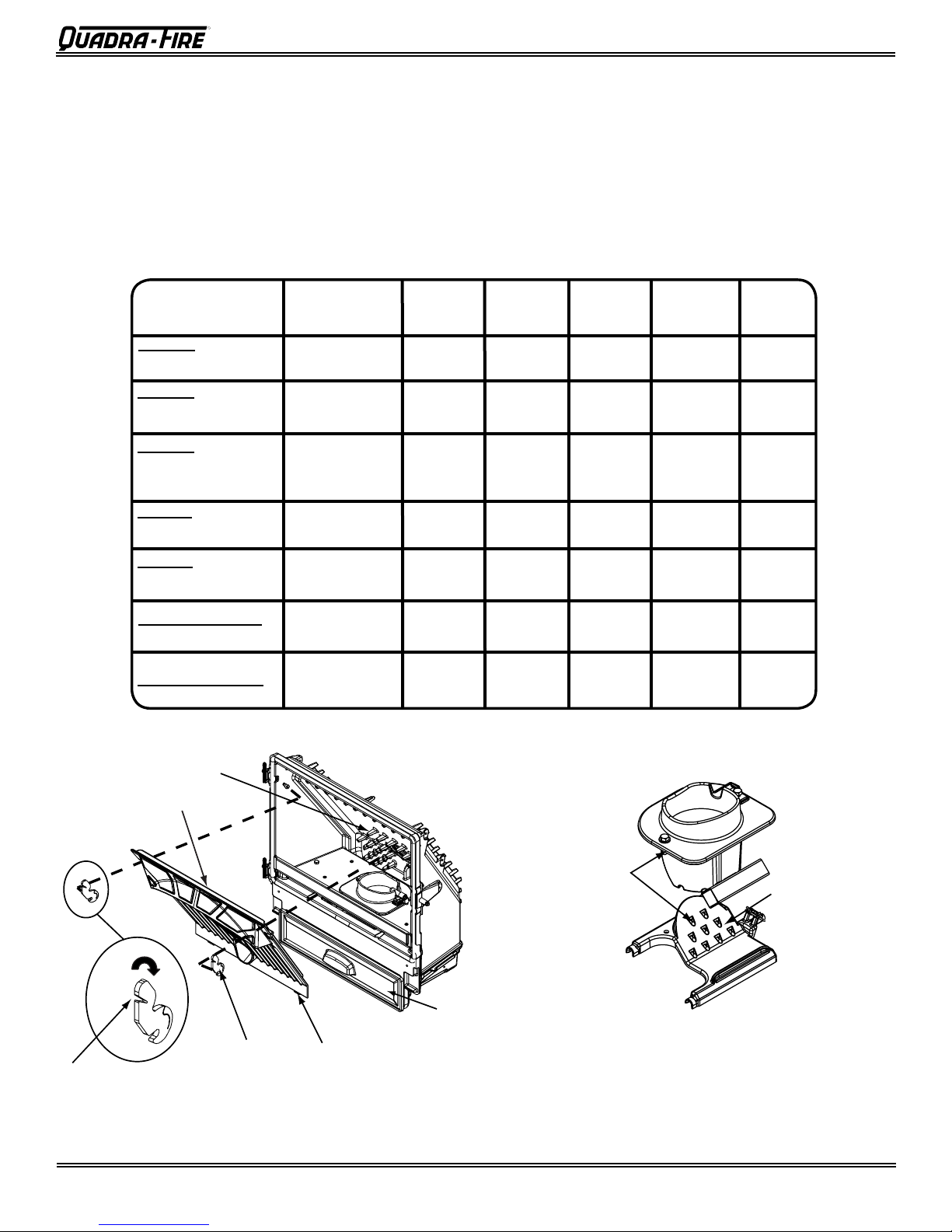
Firepot Air
Holes
Firepot
Floor
Firepot Exploded View
Baffle
Latches
Ashpan
Heat Exchanger
Insert flat head screwdriver into “V”
section and push down and the
bottom of the latch will fall forward
off of post
Locating ears - 1 on
each side. Fit behind
bottom edge
CAUTION
The appliance must be in complete shutdown, completely
cool and the exhaust blower off before performing any
cleaning or maintenance. There is a risk of shock if
the appliance is not unplugged before servicing the
appliance.
NOTE: Performing this routine service will require approximately 20
minutes a month depending on type and quality of fuel you burn.
CLEANING OR FREQUENCY DAILY WEEKLY
INSPECTION
FIREPOT
Softwood Pellets
FIREPOT
Hardwood Pellets
FIREPOT
Corn, Wheat, or Sunower Seeds
Every 5 bags
Every 3 bags
Every 1 bag
-OR-
-OR-
-OR-
PROPER SHUTDOWN PROCEDURE
1.
Set the wall control thermostat to “OFF” on AUTOMATIC/
MANUAL SETTING screen and let the appliance completely cool. The exhaust blower must be off before you
can unplug the appliance before servicing.
2. Smoke spillage into the room can occur if the appliance
is not cool before unplugging.
EVERY 2
WEEKS
YEARLY
X
X
X
ASHPAN
Wood Pellets
ASHPAN
Alternate Fuel
HEAT EXCHANGER Every 1 ton of
EXHAUST BLOWER
Every 5 bags
Daily
fuel
Every 3 tons of
fuel
-OR-
-OR-
-OR-
-OR-
X
X
X
X
FIREPOT MAINTENANCE
Page 2
The repot oor and repot air holes will need to be
scraped occasionally depending on the quality of fuel
being used. Use a putty knife, a at head screwdriver
or the repot clean-out tool provided to remove excess
carbon from the repot.
7014-139F
June 27, 2008
Page 3

R
Tools Needed: Shop Vac* and Micro Cleaning Kit*; at head
2 exhaust exits (left and right side) must
be thoroughly cleaned. Each exit is
approximately 4 inches wide, 1 inch
across and 3 inches deep.
and Phillips screwdriver; 11/2 Nut-driver or wrench.
* Shop Vac and Micro Cleaning Kit
can be purchased at your local hardware store.
1. It is necessary to remove the bafe to gain access
to the heat exchanger. Complete instructions for
removing the bafe can be found in your Owner’s
Manual.
2. Vacuum the ash from the heat exchanger with an
upholstery brush to remove the majority of the ash.
Be sure to vacuum the back of the bafe also.
Inspect the drop tube and remove any residue buildup in the drop tube. Figure 2.
.
Assemble the crevice tool from the Micro Cleaning
Kit to attach to a Shop Vac. Figure 3.
Figure 3
4.
U
se the crevice tool to nish cleaning the heat
exchanger ns. It is critical that the 2 exhaust exits
at the back of the rebox oor (left and right) be
thoroughly cleaned. Figure 4. There are several
ways this can done.
a. Use the crevice tool.
b. Attach a hose 1/2 inch (12.7mm) in diameter
and approximately 2 feet (607mm) in length to
your vacuum hose.
Use a bottle brush and push the ash down to
c.
the bottom. Remove the combustion (exhaust)
blower and then vacuum out the ash. Figures
5 through 8 on page 4.
Figure 1 - Example of a dirty heat exchanger
Figure 2
June 27, 2008
7014-139F
Figure 4
Page
Page 4

R
Vacuum out the exhaust area.
Loosen all 6 screws, but do NOT Remove
5. Removing the Combustion (Exhaust) Blower
Set blower on top of housing.
Do not disconnect the wires.
Remove (6) Nuts
Remove
Side
Panel
a. The combustion blower is mounted in the bottom
right rear of the appliance. Figure 5.
b. Use an 11/2 nut driver to loosen all 6 nuts, but do
not remove. Rotate the blower and remove from
the housing. Figure 6.
c. Set the blower on the top of the housing for the stove
and place on the rebox oor for the insert. You do
not need to disconnect the wires. Figure 7.
d. Vacuum out the exhaust area. Figure 8. You
may need to replace the gasket at this time also.
Order part SRV7000-2.
e.
A view of the inside of the exhaust area. Figure 9.
BLOWER LOCATION ON STOVE
Combustion Blower
Figure 6
Figure 7 - Stove is shown in this example
BLOWER LOCATION ON INSERT
Combustion Blower
Figure 5
Page
7014-139F
Figure 8
Figure 9
June 27, 2008
 Loading...