

Quadra-Fire MT. VERNON E2 Series, MTV-E2-PBK-C, MTV-E2-MBK-C, MTV-E2-PFT-C, MTV-E2-CSB-C Owner's Manual
...
Owner’s Manual
Operation & Care
INSTALLER: Leave this manual with party responsible for use and operation.
OWNER: Retain this manual for future reference.
Contact your dealer with questions regarding installation, operation or service.
NOTICE: DO NOT DISCARD THIS MANUAL
Please read this entire manual before use of
this pellet fuel-burning room heater. Failure to
MT. VERNON E2 PELLET STOVE
• Do not store or use gasoline or other ammable
MODEL(S):
MTV-E2-CSB-C
• Do NOT burn garbage or ammable uids such as
MTV-E2-PFT-C
• Do not over re - If heater or chimney connector
MTV-E2-PBK-C
MTV-E2-MBK-C
• Comply with all minimum clearances to combustibles
MTV-E2-PDB-C
f i r e - p a r t s . c o m
MTV-E2-PMH-C
Hot glass will cause burns.
• Do not touch glass until it is cooled
• NEVER allow children to touch glass
• Keep children away
• CAREFULLY SUPERVISE children in same room as
• Alert children and adults to hazards of high
• High temperatures may ignite clothing or other
• Keep clothing, furniture, draperies and other
NOTE
To obtain a French translation of this manual, please
contact your dealer or visit www.quadrare.com
00Pour obtenir une traduction française de ce manuel,
s’il vous plaît contacter votre revendeur ou visitez www.
quadrare.com
Tested and approved for wood pellets only. Burning of
any other type of fuel voids your warranty.
follow these instructions could result in property
damage, bodily injury, or death.
vapors and liquids in the vicinity of this or any other
appliance.
gasoline, naphtha, or engine oil in room heater.
glows, you are over ring. Over ring will void your
warranty.
as specied. Failure to comply may cause house re.
replace.
temperatures
ammable materials.
ammable materials away.
WARNING
WARNING
HOT SURFACES!
Glass and other surfaces are hot during
operation AND cool down.
CAUTION
CAUTION
Check building codes prior to installation.
• Installation MUST comply with local, regional, state
and national codes and regulations.
• Consult local building, re ofcials or authorities
having jurisdiction about restrictions, installation
inspection, and permits.
1 7080-163D August 3, 2018
MT. VERNON E2-C
ITEM PART NUMBER PART NAME QTY
1
7080-149
SERIAL LABEL PLATE
CAUTION:
R
2017
2018
2019 JAN FEB MAR APR MAY JUN
JUL AUG SEP OCT NOV DEC
NOTE: Clearances may only be reduced by means approved
by the regulatory authority having jurisdiction
A. Sample of Serial Number / Safety Label
LOCATION: Back of Stove
HOT WHILE IN OPERATION
DO NOT TOUCH, KEEP
CHILDREN, CLOTHING AND FURNITURE AWAY.
CONTACT MAY CAUSE SKIN BURNS. SEE NAMEPLATE
AND INSTRUCTIONS.
Test Lab &
Report No.
ATTENTION
CHAUD LORS DE
L'OPÉRATION. NE PAS
:
TOUCHER. GARDEZ LES ENFANTS ET LES
VÊTEMENTS LOIN DE L'ESPACE DÉSIGNÉ DE
Report:
061-S-83-2
L'INSTALLATION. LE CONTACT PEUT CAUSER DES
BRÛLURES À LA PEAU. VOIR L'ÉTIQUETTE ET LES
INSTRUCTIONS.
Model
Name
Mt Vernon E2 Pellet Stove
Listed Solid Fuel Room Heater/Pellet Type. Also suitable for Mobile Home
Installation. This appliance has been tested and listed for use in Manufactured
Homes in accordance with OAR 814-23-9000 through 814-23-909.
Appareil de chauffage de combustible solide/de type de boulettes. Accepté dans
f i r e - p a r t s . c o m
l'installation dans les maisons mobiles. Cet appareil a été testé et enregistré pour
l'usage dans les Maisons Mobiles en accord avec OAR 814-23-9000 jusqu'à
814-23-909.
PREVENT HOUSE FIRES / PRÉVENTION DES FEUX DE MAISON
Install and use only in accordance with manufacturer's installation and operating
instructions. Contact local building or fire officials about restrictions and inspection in
your area.
WARNING - FOR MOBILE HOMES: Do not install appliance in a sleeping room. An
outside combustion air inlet must be provided. The structural integrity of the mobile
home floor, ceiling and walls must be maintained. Refer to manufacturer's
instructions and local codes for precautions required for passing chimney through a
combustible wall or ceiling. Inspect and clean vent system frequently in accordance
with manufacturer's instructions. DO NOT CONNECT THIS UNIT TO A CHIMNEY
SERVING ANOTHER APPLIANCE. Use a 3" or 4" diameter type "L" or "PL" venting
system.
Installez et utilisez en accord avec les instructions d'installation et d'opération du
fabricant. Contactez le bureau de la construction ou le bureau des incendies au sujet
des restrictions et des inspections d'installation dans votre voisinage. Ne pas obstruez
l'espace en dessous de l'appareil.
AVIS - Pour Les Maisons Mobiles: Ne pas installer dans une chambre à coucher. Un
tuyau extérieur de combustion d'air doit être installé et ne doit pas être obstrué
lorsque l'appareil est en usage. La structure intégrale du plancher, du plafond et des
murs de la maison mobile doit être maintenue intacte. Référez vous aux instructions
du fabricant et des codes locaux pour les précautions requises pour passer une
cheminée à travers un mur ou un plafond combustibles, et les compensations
SAMPLE
maximums. Inspectez et nettoyez la cheminée fréquemment. Ne pas connecter cet
appareil à une cheminée servant un autre appareil. Utilisez systèm de ventilation "L"
ou "PL" diamètre 76mm ou 102mm
C
B
G
Owners Manual Install Manual
D
A
USA
H
G = 2 in
H* = 2 in
I = 6 in
G
CANADA
G = 200 mm
I
H* = 200 mm
I = 450 mm
MINIMUM CLEARANCES TO COMBUSTIBLE MATERIALS
ESPACES LIBRES MINIMUM DES MATÉRIAUX
A Back Wall / Mur Arrière 2 in [51 mm]
B Side Wall / Mur De Côté 6 in [152 mm]
D
C “L” or “PL” Pipe to Back Wall / “L” ou “PL” Un Tuyau Mur Arrière 1 in [25 mm]
D Side Wall / Mur De Côté 2 in [51 mm]
FLOOR PROTECTION / PROTECTION DU SOL
Floor protector must be non-combustible
material, extending beneath heater and to
the front/sides/rear as indicated. Measure
front distance (I) from the surface of the
glass door.
Le poêle doit être placé sur une assise non
combustible s’étendant tout autour de lui,
comme les schémas l’indiquent. Mesurez la
distance du devant (I) de la surface de la
porte vitrée.
Manufactured by:Fabriqué par
352 Mountain House Road, Halifax, PA 17032
www.quadrafire.com
U.S. ENVIRONMENTAL PROTECTION AGENCY
Certified to comply with 2015 particulate emission standards at 0.5 g/hr EPA Methods
28 and 5G. Not approved for sale after May 15, 2020
DO NOT REMOVE THIS LABEL / NE PAS ENLEVER L'ÉTIQUETTE
Fabriqué aux États-Unis-d’Amérique par des pièces d’origine américaine et pièces importées.
Serial No. / N° de série
HF
Conforms to ASTM Std E1509-12. Certified to ULC S627-00. Room Heating Pellet
BurningType, (UM) 84-HUD FOR USE ONLY WITH PELLETIZED WOOD FUEL. Do
not use any other type of fuel.
Input Rating: 55,000 Btu's/hr. Electrical Rating:115 VAC, 60 Hz, Start 2.9 Amps, Run
2.45 Amps. Route power cord away from unit. Do not route cord under or in front of
appliance. Do not obstruct the space beneath the heater.
DANGER: Risk of electrical shock. Disconnect power supply before servicing.
Replace glass only with 5mm ceramic. To start, turn dial control to desired setting and
set thermostat above room temperature, the stove will light automatically. To
shutdown, turn dial control to OFF or set thermostat below room temperature. For
further instruction refer to owner's manual. Keep viewing doors tightly closed during
operation. Keep viewing and ash removal doors tightly closed during operation.
Conforme à la norme ASTM E1509-12 Std. Certifié à la norme ULC S627-00. Room
Heating Pellet Burning Type, (UM) 84-HUD POUR USAGE AVEC LES BOULETTES
DE BOIS. N’utiliser aucun autre genre de combustible.
Puissance de Rendement: 55,000 Btu's/hr. Puissance Électrique: 115 VAC, 60 Hz,
Début 2.9 Amps, Courir 2.45 Amps, Éloignez le fil électrique de l'appareil. Ne pas faire
passer le fil électrique au dessus ou en dessous de l'appareil. Ne pas bloquer
l’espace au dessous de l’appareil.
DANGER: Il y a risque de décharge électrique. Déconnectez le fil électrique de la
prise de contact avant le service. Remplacez la vitre seulement avec une vitre
céramique de 5 mm disponible chez votre fournisseur. Pour commencer, tournez la
molette de réglage à la température désirée et réglez le thermostat au-dessus de la
température ambiante, le poêle s'allumera automatiquement. Pour éteindre, tournez la
molette de réglage sur OFF ou réglez le thermostat dessous de la température
ambiante. Pour des instructions supplémentaires, référez vous au manuel du
propriétaire. Gardez la porte d'ouverture et la porte des cendres fermées
hermétiquement durant l'opération.
*Non-combustible floor protection must extend 2 inches
(51mm) beneath the flue pipe when installed with horizontal
venting or under the Top Vent Adapter with vertical installation.
RECOMMENDED IN USA; REQUIRED IN CANADA.
*Un protecteur incombustible de plancher doit s'étendre 2
inches (51mm) sous le conduit de cheminée pour une
installation de ventilation horizontale ou sous un adapteur de
ventilation de dessus pour une installation verticale.
RECOMMANDÉ AUX ÉTATS-UNIS; NÉCESSAIRE AU
CANADA.
This wood heater needs periodic inspection
and repair for proper operation. Consult the
owner’s manual for further information. It is
against federal regulations to operate this
wood heater in a manner inconsistent with the
operating instructions in the owner’s manual
Made in U.S.A. of US and imported parts.
BARCODE LABEL
7080-133_R3
Serial No.
Mfg. Date
2 7080-163D August 3, 2018
MT. VERNON E2-C
Safety Alert Key:
• DANGER! Indicates a hazardous situation which, if not avoided will result in death or serious injury.
• WARNING! Indicates a hazardous situation which, if not avoided could result in death or serious injury.
• CAUTION! Indicates a hazardous situation which, if not avoided, could result in minor or moderate injury.
• NOTICE: Indicates practices which may cause damage to the appliance or to property.
TABLE OF CONTENTS
A. Sample of Serial Number / Safety Label ......... 2
B. Warranty Policy ............................ 4
C. Quick Start Guide .......................... 7
1 Listing and Code Approvals ..............8
A. Appliance Certication ......................8
B. BTU & Efciency Specications ............... 8
C. Glass Specications........................9
D. Electrical Rating ........................... 9
E. Mobile Home Approved .....................9
F. Sleeping Room ............................ 9
G. California - Prop65 ......................... 9
2 Operating Instructions .....................10
A. Fire Safety ............................... 10
B. Non-Combustible Materials .................. 10
C. Combustible Materials...................... 10
D. Fuel Material and Fuel Storage .............. 10
f i r e - p a r t s . c o m
E. Before Your First Fire ...................... 11
F. Filling the Hopper.......................... 11
G. User Dial Control ......................... 11
H. Normal Startup Sequence................... 11
I. Fire Characteristics......................... 11
J. Fire pot Purge ............................ 12
K. Ignition Cycles ............................ 12
L. Restarting the Appliance .................... 12
M. Shutdown ............................... 12
N. Clear Space ............................. 13
O. Trim Adjustment .......................... 13
P. Your Pellet Appliance’s General Operating Parts . 14
Q. LED Color Coding Chart and Explanation ......15
R. Thermostat Controls ....................... 16
S. Thermostat Setup Options...................16
T. Thermostat Operation Instructions.............17
U. Thermostat Temperature Programs ........... 17
V. Thermostat Other Features .................. 18
W. Thermostat Battery Replacement............. 19
X. Frequently Asked Questions ................20
3 Maintenance and Service ................. 21
A. Proper Shutdown Procedure ................. 21
B. Quick Reference Maintenance Chart .......... 21
C. General Maintenance and Cleaning........... 22
D. Soot or Creosote Fire Awareness .............25
E. High Ash Fuel Content Maintenance........... 26
F. Bafe Removal ...........................26
G. Glass Replacement ....................... 26
H. Convection Blower Replacement ............ 27
I . Combustion/Exhaust Blower Replacement ..... 27
4 Troubleshooting Guide .....................28
5 Reference Materials .......................... 32
A. Component Functions ..................... 32
B. Service and Maintenance Log................33
C. Exploded Drawings ........................ 36
D. Parts List ................................ 37
Quadra-Fire is a registered trademark of Hearth & Home Technologies.
August 3, 2018 7080-163D 3
MT. VERNON E2-C
Vent Free burners, Vent Free ceramic fiber logs,
Aluminized Burners
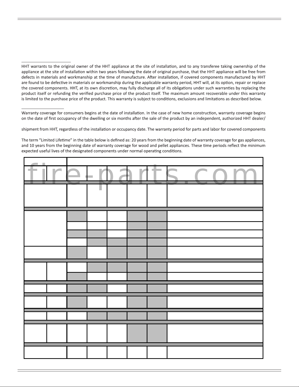
B. Warranty Policy
Hearth & Home Technologies
LIMITED LIFETIME WARRANTY
Hearth & Home Technologies, on behalf of its hearth brands (“HHT”), extends the following warranty for HHT gas, wood, pellet and
electric hearth appliances that are purchased from an HHT authorized dealer.
WARRANTY COVERAGE:
WARRANTY PERIOD:
distributor, whichever occurs earlier. However, the warranty shall commence no later than 24 months following the date of product
is produced in the following table.
Warranty Period HHT Manufactured Appliances and Venting
Parts Labor Gas Pellet Wood Electric Venting Components Covered
f i r e - p a r t s . c o m
1 Year
2 years
3 years
5 years 1 year
6 years 3 years
7 years 3 years
X X X
X X
X X X
X
X
X
X X
X X
xX
X
X
All parts and material except as covered by
Conditions, Exclusions, and Limitations listed
Igniters, auger motors, electronic components, and
glass
Factory-installed blowers
Molded refractory panels
Ignition Modules
Firepots, burnpots, mechanical feeders/auger
assemblies
Castings and Baffles
Catalyst - limitations listed
Manifold tubes, HHT chimney and termination
10 years 1 year
Limited
Lifetime
3 years
90 Days
X
X X X
X X X X X
Firebox and heat exchanger, Grate and Stainless
Steel Burners, FlexBurn® System (engine, inner
All replacement parts beyond warranty period
Burners, logs and refractory
cover,access cover and fireback)
4021-645J • 08-03-171
4 7080-163D August 3, 2018
MT. VERNON E2-C
WARRANTY CONDITIONS:
• This warranty only covers HHT appliances that are purchased through an HHT authorized dealer or distributor. A list of HHT
authorized dealers is available on the HHT branded websites.
•
• This warranty is only valid in the country in which the HHT authorized dealer or distributor that sold the appliance resides.
• Contact your installing dealer for warranty service. If the installing dealer or distributor is unable to provide necessary parts, contact
other than the dealer from whom you originally purchased the product.
• Check with your dealer in advance for any costs to you when arranging a warranty call. Travel and shipping charges for parts are not
covered by this warranty.
• Limited Catalyst Warranty
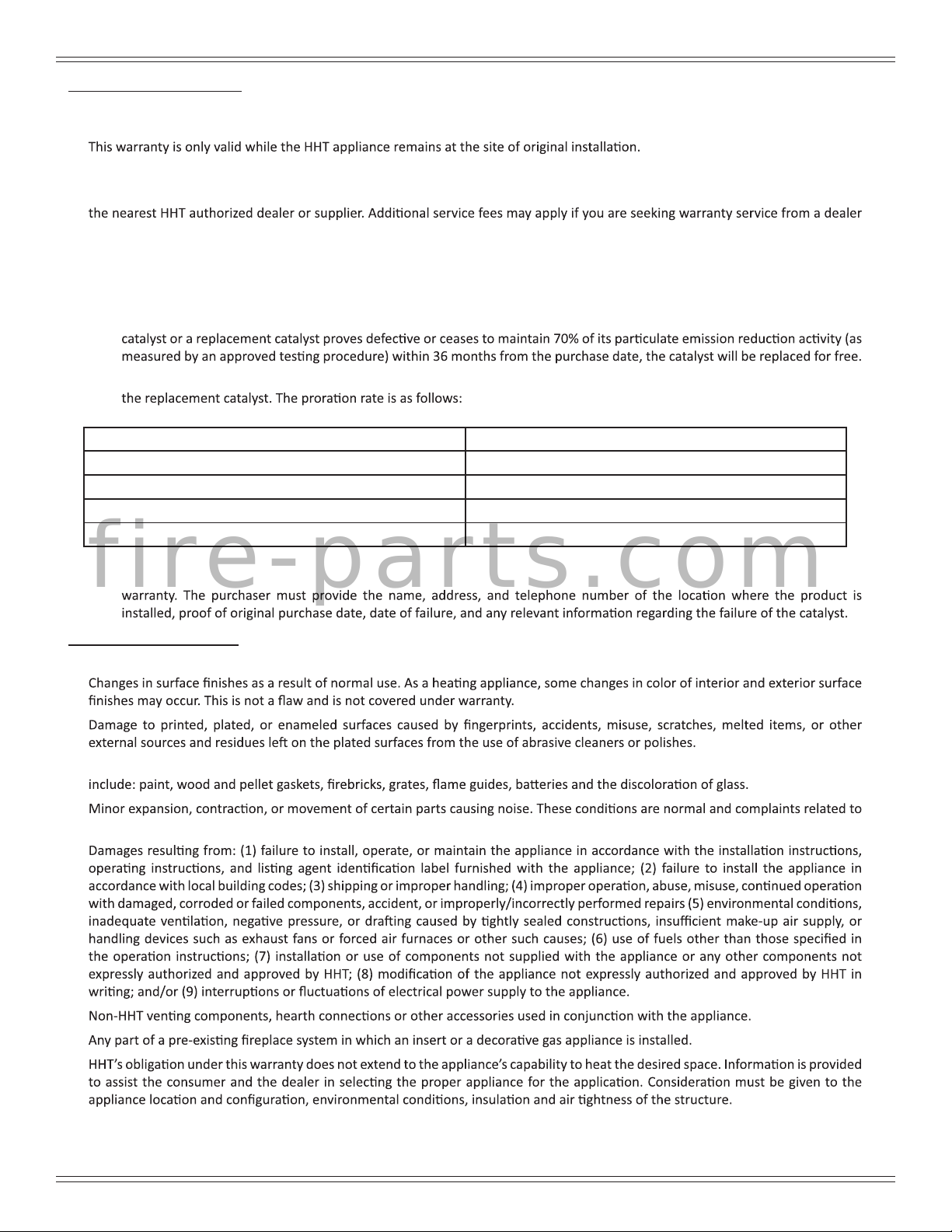
o For wood burning products containing a catalyst, the catalyst will be warranted for a six-year period as follows: if the original
o From 37 to 72 months a pro-rated credit will be allowed against a replacement catalyst and labor credit necessary to install
Amount of Time Since Purchase Credit Towards Replacement Cost
0 - 36 Months 100%
37 - 48 Months 30%
49 - 60 Months 20%
61 - 72 Months 10%
o Any replacement catalyst will be warranted under the terms of the catalyst warranty for the remaining term of the original
f i r e - p a r t s . c o m
WARRANTY EXCLUSIONS:
This warranty does not cover the following:
•
•
• Repair or replacement of parts that are subject to normal wear and tear during the warranty period are not covered. These parts
•
this noise are not covered by this warranty.
•
•
•
•
4021-645J • 08-03-172
August 3, 2018 7080-163D 5
MT. VERNON E2-C
This warranty is void if:
•
•
• There is any damage to the appliance or other components due to water or weather damage which is the result of, but not limited
LIMITATIONS OF LIABILITY
•
have other rights, which vary from state to state. EXCEPT TO THE EXTENT PROVIDED BY LAW, HHT MAKES NO EXPRESS WARRANTIES
OTHER THAN THE WARRANTY SPECIFIED HEREIN. THE DURATION OF ANY IMPLIED WARRANTY IS LIMITED TO DURATION OF THE
EXPRESSED WARRANTY SPECIFIED ABOVE.
f i r e - p a r t s . c o m
4021-645J • 08-03-173
6 7080-163D August 3, 2018
C. Quick Start Guide
June 18, 2018
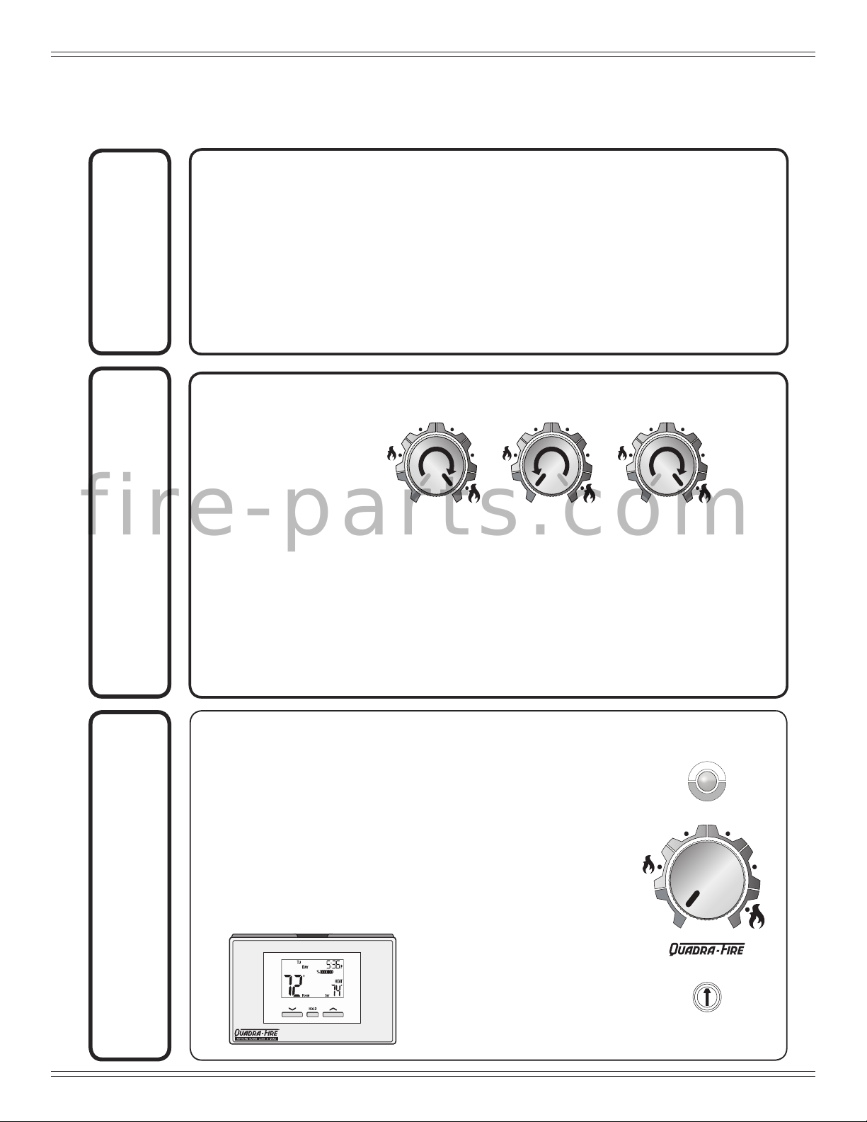
QUICK START GUIDE
*Before you plug in this appliance, follow these instructions*
Run Set UpPrime
1. Empty Fire box
2. Add pellets and close lid
3. Turn DIAL to OFF
4. Plug in the appliance
• Exhaust blower will run for about 45 Seconds (wait for it to stop
before priming)
• Green light will start ashing
5. Ensure thermostat is connected properly per included instructions.
1. After the exhaust blower has stopped; quickly turn the dial from OFF
to HI two times:
• The LIGHT will turn solid green and pellets will feed. Wait for 2 minutes
• If the LIGHT did not turn solid green:
- Turn dial back to OFF
- Unplug appliance, plug it back in and repeat
Priming is only needed for rst re or starting re on empty hopper.
NOTE: The prime function is only required during initial set up of the unit, or after
the unit has alarmed out due to an empty hopper. Priming while under
normal operating conditions will cause the re pot to over ll.
H
E
A
T
S
E
T
T
I
N
G
H
E
A
T
S
E
T
T
I
N
G
O
F
F
HI
LO
H
E
A
T
S
E
T
T
I
N
G
H
E
A
T
S
E
T
T
I
N
G
O
F
F
HI
LO
H
E
A
T
S
E
T
T
I
N
G
H
E
A
T
S
E
T
T
I
N
G
O
F
F
HI
LO
It may take as long as 10
minutes to achieve a re in the
re pot. Turning the knob or
thermostat to off during this time
will interrupt the startup process.
1. While thermostat is in RUN
mode, the set temperature
can be temporarily changed
by pressing UP
.
0
-
1
-
2
-
3
-
4
+
1
+
2
+
3
+
4
A
L
A
R
M
O
N
H
E
A
T
S
E
T
T
I
N
G
H
E
A
T
S
E
T
T
I
N
G
O
F
F
HI
LO
Control Panel
Light
Dial
Trim
*The temporarily changed set temperature
will return to the programmed value stored
in memory when start time of the next
upcoming scheduled event is reached
(MORN, DAY, EVE, OR NITE).
**Appliance will not turn on unless target
temperature is a higher temperature than
the room temperature.
2. Choose Setting:
• LO – HI*
• Green LIGHT will
begin ashing and
stove will start
*For rst re, HHT
recommends running
on HI for rst 30
minutes
MT. VERNON E2-C
f i r e - p a r t s . c o m
August 3, 2018 7080-163D 7

MT. VERNON E2-C
1 Listing and Code Approvals
A. Appliance Certication
Model Mt. Vernon Pellet Stove E2
Laboratory OMNI Test Laboratories, Inc.
Report No. 061-S-83-2
Type
Standard
Solid Fuel Room Heater, Pellet Fuel
Burning Type
ASTM E1509-12, ULC S627-00 and
(UM) 84-HUD, Mobile Home Approved.
Complies with Part 15 of FCC Rules.
Operation is subject to the following two
conditions: (1) this device may not cause
FCC
harmful interference, and (2) this device
must accept any interference received,
including interference that may cause
undesired operation.
f i r e - p a r t s . c o m
B. BTU & Efciency Specications
Emissions Report
Number:
EPA Certication #: 98-17
EPA Certied Emissions: 0.74 g/hr
*LHV Tested Efciency: 83.2%
**HHV Tested Efciency: 77.9%
***EPA BTU Output: 12,682 - 39,428 / HR
****BTU Input: 16,396 - 50,775 / HR
Vent Size: 3 or 4, “L” or “PL”
Hopper Capacity: 80 lbs.
* Weighted average LHV efciency using data collected
during EPA emissions test.
**Weighted average HHV efciency using data collected
during EPA emissions test.
***A range of BTU outputs based on HHV and the burn
rates from the low and high EPA tests.
****Based on the maximum feed rate per hour multiplied
by approximately 8600 BTU’s which is the average BTU’s
from a pound of pellets.
0061PS094E
Fuel Wood Pellets
NOTICE: This installation must conform with local codes. In the absence of local codes you must comply with the ASTM
E1059-12, ULC S627-00, (UM) 84-HUD and ULC/ORD-C-1482.
The Quadra-Fire Mt. Vernon E2 Pellet Appliance meets the U.S. ENVIRONMENTAL PROTECTION AGENCY Certied
to comply with 2020 particulate emission standards at 0.74 G/HR EPA CFR subpart AAA, using ASTM E2779-10, ASTM
2515-11 Method- Pellet Appliance sections, CSA B415.1-10.
This pellet appliance needs periodic inspection and repair for proper operation. It is against federal regulations to operate
this pellet appliance in a manner inconsistent with the operating instructions in the owner’s manual.
8 7080-163D August 3, 2018
MT. VERNON E2-C
C. Glass Specications
This stove is equipped with 5mm ceramic glass. Replace
glass only with 5mm ceramic glass. Please contact your
dealer for replacement glass.
D. Electrical Rating
115 VAC, 60 Hz, Start 2.9 Amps, Run 2.45 Amps
E. Mobile Home Approved
• This appliance is approved for mobile home
installations when not installed in a sleeping room and
when an outside combustion air inlet is provided.
• The structural integrity of the mobile home oor, ceiling,
and walls must be maintained.
• The appliance must be properly grounded to the frame
of the mobile home and use only Listed pellet vent
Class “L” or “PL” connector pipe.
• Outside Air Kit (OAK-3) must be installed in a mobile
home installation.
F. Sleeping Room
When installed in a sleeping room it is recommended that
3ft of vertical be installed prior to horizontally exiting the
room and a smoke/CO alarm be installed in the bedroom.
The size of the room must be at least 50ft³ per 1,000 Btu/hr
stove input, if the stove exceeds the room size, out air must
be installed.
G. California - Prop65
f i r e - p a r t s . c o m
• Installation and use of any damaged appliance.
• Modication of the appliance.
• Installation other than as instructed by Hearth &
• Installation and/or use of any component part not
• Operating appliance without fully assembling all
• Operating appliance without legs attached (if
• Do NOT Over re - If appliance or chimney connector
Any such action that may cause a re hazard.
Improper installation, adjustment, alteration, service or
maintenance can cause injury or property damage.
For assistance or additional information, consult a qualied
installer, service agency or your dealer.
NOTE: Hearth & Home Technologies, manufacturer
WARNING
This product and the fuels used to operate this product (wood), and
the products of combustion of such fuels, can expose you to
chemicals including carbon black, which is known to the State of
California to cause cancer, and carbon monoxide, which is known to
the State of California to cause birth defects or other reproductive
harm. For more information go to: WWW.P65Warnings.ca.gov
Fire Risk.
Hearth & Home Technologies disclaims any
responsibility for, and the warranty will be voided
by, the following actions:
Home Technologies.
approved by Hearth & Home Technologies.
components.
supplied with unit).
glows, you are over ring.
of this appliance, reserves the right to alter its
products, their specications and/or price without
notice.
WARNING
August 3, 2018 7080-163D 9
MT. VERNON E2-C
User Guide
2 Operating Instructions
Fuel Material
WARNING
Fire Risk.
• Do not operate appliance before reading and
understanding operating instructions.
• Failure to operate appliance properly may
cause a house re.
Visit www.quadrare.com/shopping-tools/videos to view
product and use & care videos.
A. Fire Safety
To provide reasonable re safety, the following should be
given serious consideration:
• Install at least one smoke detector and CO monitor on
each oor of your home.
• Locate detectors away from the heating appliance and
close to the sleeping areas.
• Follow the detector’s manufacturer’s placement and
installation instructions and maintain regularly.
• Conveniently locate a Class A re extinguisher to
contend with small res.
• In the event of a hopper re:
f i r e - p a r t s . c o m
• Evacuate the house immediately.
• Notify re department.
B. Non-Combustible Materials
Material which will not ignite and burn, composed of any
combination of the following:
- Steel - Plaster - Glass - Tile
- Brick - Iron - Slate - Concrete
Materials reported as passing ASTM E 136, Standard
Test Method for Behavior of Metals, in a Vertical Tube
Furnace of 750° C.
C. Combustible Materials
Material made of/or surfaced with any of the following
materials:
- Compressed Paper - Wood - Plywood/OSB
- Sheet Rock (drywall) - Plastic - Plant Fibers
Any material that can ignite and burn: ame proofed or not,
plastered or non-plastered.
D. Fuel Material and Fuel Storage
Pellet fuel quality can greatly uctuate. This appliance has
been designed to burn a wide variety of fuels, giving you
the choice to use the fuel that is most economical in your
region.
• Made from sawdust or wood by-products
• Depending on the source material it may have a high or
low ash content.
Higher Ash Content Material
• Hardwoods with a high mineral content
• Fuel that contains bark
• Standard grade pellets, high ash pellets
Lower Ash Content Material
• Softwoods
• Fuels with low mineral content
• Premium grade pellets
CAUTION!
Do not burn fuel that contains an additive; (such as
soybean oil).
• May cause hopper res
• Damage to product may result
Read the ingredients list on the package.
Clinkers
Minerals and other non-combustible materials such as sand
will turn into a hard, glass-like substance called a clinker
when heated in the re pot.
Trees from different areas will vary in mineral content. That
is why some fuels produce more clinkers than others.
Moisture
Always burn dry fuel. Burning fuel with high moisture
content takes heat from the fuel and tends to cool the
appliance, robbing heat from your home. Damp pellet fuel
can clog the feed system.
Size
• Pellets are either 1/4 inch or 5/16 inch (6-8mm) in
diameter
• Length should be no more that 1-1/2 inches (38mm)
• Pellet lengths can vary from lot to lot from the same
manufacturer
• Due to length variations, the ame height (feed rate)
may need adjusting occasionally. See page 25 for
instructions.
Hearth & Home Technologies strongly recommends only
using Pellet Fuel Institute (PFI) certied fuel.
10 7080-163D August 3, 2018
MT. VERNON E2-C
A
L
A
R
M
O
N
Performance
• Higher ash content requires the ash drawer to be
emptied more frequently
• Hardwoods require more air to burn properly
• Premium wood pellets produce the highest heat output.
• Burning pellets longer than 1-1/2 inches (38mm) can
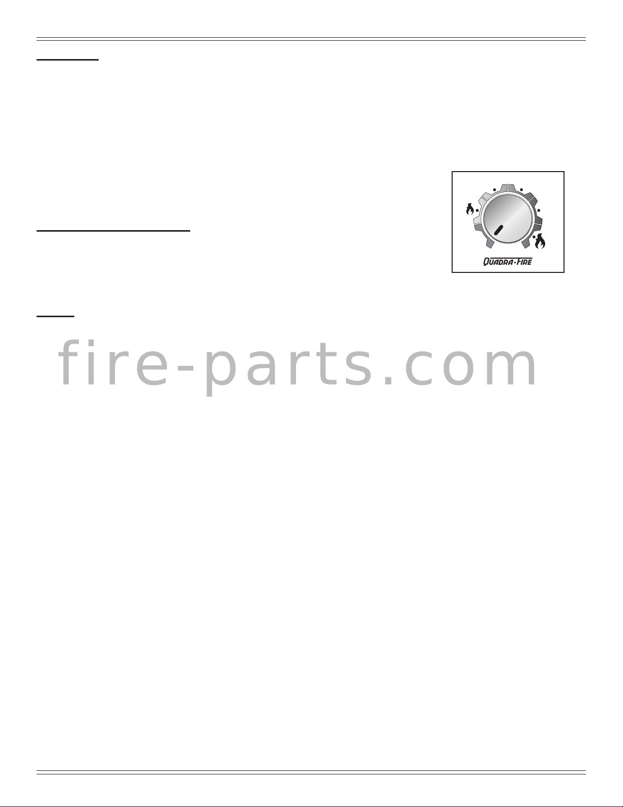
G. User Dial Control
The appliance has one dial control located on the side of
the unit (behind a drop door) used for changing the heat
setting and restarting the appliance. There are ve heat
settings on this dial ranging to include: LOW, MED-LOW,
MED, MED-HIGH, and HIGH. Figure 11.1
cause an inconsistent fuel feed rate and/or missed
ignitions.
Turn the dial control to the desired heat setting and turn the
appliance ON and OFF using the thermostat.
We recommend that you buy fuel in multi-ton lots whenever
possible. However, we do recommend trying various
brands before purchasing multi-ton lots to ensure your
satisfaction.
Changing to Different Fuel Type
• Empty the hopper of the previous fuel
LO
O
F
F
• Thoroughly vacuum hopper before lling with the new
fuel
Figure 11.1
The burn rate, BTU content and heat output will all vary
depending on the fuel selected.
H. Normal Startup Sequence
Storage
• Wood pellets should be left in their original sealed bag
until using to prevent moisture absorption.
• This will also prevent rodents from becoming a
problem
.
• Do not store any pellet fuel within the clearance
f i r e - p a r t s . c o m
requirements or in an area that would hinder routine
cleaning and maintenance.
E. Before Your First Fire
1. First, make sure your appliance has been properly
installed and that all safety requirements have been
met. Pay particular attention to the re protection,
venting and thermostat installation instructions.
2. Double check that the ash drawer and rebox are
empty!
3. Close the front door.
IMPORTANT DETAIL: THE TIP OF THE
THERMOCOUPLE MUST BE IN CONTACT WITH THE
INSIDE END OF THE THERMOCOUPLE COVER OR
MISSED IGNITIONS CAN OCCUR.
F. Filling the Hopper
Open the hopper lid by lifting the handle. Fill the hopper
with fuel. Close the hopper lid. The unit will not feed with
the hopper lid open and the re will go out.
The unit will go into the ignition sequence followed by a
start up sequence (the green LED will ash rapidly).
The ignition sequence involves the exhaust blower and
igniter turning on, and the feed motor running in two stages.
The rst stage involves the feed motor running continu ously
for about a minute to start loading pellets into the re pot.
In the second stage, the feed motor will begin cycling on
and off.
When the pellets are warming - on the verge of igniting - it
is not uncommon for the rebox to ll with smoke.
Once ignition happens, the smoke should quickly
disappear. During this stage, as well as any part during the
burn process, the front door should not be opened.
This startup cycle continues until the unit senses ignition
by a rise in the exhaust temperature or the unit times out.
Following the ignition cycle the unit continues to feed
pellets to build up the re.
After warming up, the convection blower will begin to blow
warm air into the room. As the appliance increases heat
the blower will increase its output.
I. Fire Characteristics
A properly adjusted re with the heat output control switch
set on “high” has a short active ame pattern that extends
out of the re pot approximately 4 inches (102mm). If the
re has tall ames with black tails and seems somewhat
lazy, the feed rate will need to be reduced. This is done
by sliding the fuel adjustment control rod down, which will
reduce the feed. If the re is not 4 inches (102mm) tall,
slide the fuel adjustment control rod up to increase the
feed. A medium and low setting will give a shorter ame.
The ame will rise and fall somewhat. This is normal.
E
E
T
T
S
S
T
T
T
T
I
I
N
N
A
A
E
E
G
H
H
G
HI
August 3, 2018 7080-163D 11
MT. VERNON E2-C
J. Fire pot Purge
Purpose: To help remove debris from the re pot and help
the unit burn as efcient as possible.
The frequency of the purge cycle is once every 30 minutes
while the unit is burning. During the re pot purge, the feed
is reduced to the lowest setting and the exhaust blower
ramps up to a very high setting. The purge cycle lasts 99
seconds.
The purge cycle does not replace daily cleaning.
K. Ignition Cycles
1. At the beginning of each ignition cycle, it is normal to
see some smoke in the rebox. The smoke will stop
once the re starts.
2. The convection blower will automatically turn on after
your appliance has been burning for approximately
10 minutes. This blower transfers heat from your
appliance into the room, and will continue to run after
the thermostat has stopped calling for heat until the
appliance has cooled down.
3. Occasionally the appliance may run out of fuel and shut
itself down. When this happens, the red call light will be
on (See Table on page 14). To restart, ll the hopper
and follow section on Restarting the Appliance. You
should see a re shortly. If not, follow the instructions
on page 11, of “Normal Startup Sequence”.
f i r e - p a r t s . c o m
WARNING
Fire Risk
Do NOT operate appliance:
• With appliance door open.
• Fire pot oor open.
Do NOT store fuel:
• Closer than required clearances to
combustibles to appliance
• Within space required for loading or ash
removal.
L. Restarting the Appliance
Restart Process
1. When the unit has run out of fuel and the “empty
hopper” error code illuminates, add pellet fuel to the
hopper.
2. Dump the ashes and clinkers built up in the re pot by
pulling the ash dump removal handle out several times.
Make sure clinkers have dropped into the ash pan then
return the handle to fully closed position.
3. Turn the dial control to OFF and then up to high 2X to
prime.
4. After seeing pellets drop then turn to desired setting to
reset the appliance control system. The appliance will
then being its startup sequence.
Restarting After a Power Failure
1. For an electrical disruption the appliance will start on
its own without need for priming - providing the control
system is asking for heat.
2. The appliance will always go through a normal
shutdown sequence before restarting.
M. Shutdown
To shut the appliance down, turn the dial control to OFF or
turn the thermostat to OFF. During the shutdown process,
the light will ash amber or green rapidly.
Unlike the re pot purge, during shutdown existing fuel in
the re pot will continue to burn without the feed motor run-
ning; but, the exhaust and convection blowers will remain
on until the exhaust has cooled.
NOTE: If maintenance or daily cleaning is going to be
conducted immediately following a shutdown,
please use caution as components especially those
inside the rebox may still be hot.
Due to safety precautions:
• If the dial control is turned to OFF and back on (even
if by mistake) the unit will go through the shutdown
sequence before restarting.
• Additionally, if the thermostat is turned to “OFF” during
operation the appliance will go through a shutdown
sequence before restarting.
CAUTION
HOT WHILE IN OPERATION. KEEP CHILDREN,
CLOTHING AND FURNITURE AWAY. CONTACT MAY
CAUSE SKIN BURNS.
12 7080-163D August 3, 2018

MT. VERNON E2-C
N. Clear Space
Mantel:
objects on mantel or hearth. Heat may damage these
objects.
NOTICE: Clearances may only be reduced by means
Avoid placing candles and other heat-sensitive
approved by the regulatory authority having
jurisdiction.
WARNING
Fire Risk.
Do NOT place combustible objects in front of the
appliance. High temperatures may ignite clothing,
furniture or draperies. Maintain a minimum
clearance of 3 feet (914mm) in front of appliance.
O. Trim Adjustment
Figure 13.1
Trim adjustment is the small dial located below the
main dial control. The function of the trim adjustment
is to allow for variations in elevation, venting and
installation congurations, and fuel types (hard
wood/soft wood).
WARNING
Fire Risk.
Keep combustible materials, gasoline and other
ammable vapors and liquids clear of appliance.
• Do NOT store ammable materials in the appliance’s
vicinity.
• DO NOT USE GASOLINE, LANTERN FUEL,
KEROSENE, CHARCOAL LIGHTER FLUID OR
f i r e - p a r t s . c o m
SIMILAR LIQUIDS TO START OR “FRESHEN UP”
A FIRE IN THIS Appliance.
• DO NOT BURN GARBAGE OR FLAMMABLE
FLUIDS SUCH AS GASOLINE, NAPHTHA OR
ENGINE OIL.
• DO NOT USE CHEMICALS OR FLUIDS TO START
THE FIRE.
• Keep all such liquids well away from the appliance
while it is in use.
• Combustible materials may ignite.
Rotating this dial will adjust the air/fuel ratio to the
appliance:
• Clockwise adjustments increase the ame
height.
• Counter-clockwise adjustments will
decrease the ame height.
• When changing trim settings only adjust 1
level at a time, allowing 15 minutes for re to
stabilize before making another adjustment.
• The factory default trim adjustments are set
to zero (0) for most fuels and recommended
venting congurations.
A properly adjusted re will have a bright, active
ame pattern that extends out of the re pot
approximately 6 to 9 inches when burning on high.
A properly adjusted re will burn cleaner and have
higher efciencies. Please copy and paste the follow
web address: http://www.quadrare.com/Owner-
Resources/Use-and-Care-Videos/Mt-VernonE2-Pellet-Stove-Insert.aspx and watch the video
regarding Normal Operation.
August 3, 2018 7080-163D 13

MT. VERNON E2-C
Ash Dump Lever
Baffle Latch
Firepot
Baffle
Dial
Control
Hopper
Switch
P. Your Pellet Appliance’s General Operating Parts
f i r e - p a r t s . c o m
14 7080-163D August 3, 2018

Q. LED Color Coding Chart and Explanation
The number of ashes between pauses is per one second unless otherwise indicated.
MT. VERNON E2-C
LED
Color
Green
Green
Green
Green 1X Stage 1: Low heat BTU Range: 14,620 - 19,694 Average: 19,054
Green 2X Stage 2: Med-Low heat BTU Range: 22,102 - 23,506 Average: 22,735
Green 3X Stage 3: Med heat BTU Range: 30,778 - 32,680 Average: 31,603
Green 4X Stage 4: Med-Hi heat BTU Range: 38,576 - 42,914 Average: 40,665
Green 5X Stage 5: Hi heat BTU Range: 49,830 - 52,460 Average: 51,528
Amber
Red 1X Empty Hopper Alarm
Red 2X Exhaust Probe Alarm
Red 4X Missed Ignition
Red 6X Encoder Alarm
Red 8X
No. of Flashes
between pauses
Steady ON while
priming feed tube
(max time
2 min utes)
1x every 2
seconds
Blinks
Continuously
Blinks
Continuously
f i r e - p a r t s . c o m
Description Notes
Feed Motor is running
continuously.
(priming the feed tube)
Unit is on standby To start appliance, follow start up sequence.
Appliance is in the start
up/ignition sequence or in
shutdown.
Appliance is in the
shutdown sequence.
Exhaust Over
Temperature Alarm
When priming the feed system and lling the re pot, DO
NOT OVERFILL Fire pot FOR IGNITION. The unit will
automatically go into start up following the prime function.
During shut down, the blowers will shut off when the exhaust
temperature has cooled.
During shut down, the blowers will shut off when the exhaust
temperature has cooled.
This alarm is caused by the re going out from lack of fuel.
Reset by turning to “OFF” then turn dial to desired setting.
Failed component error. See troubleshoot ing section for
more information.
There are a total of 2 tries per ignition sequence. If after
2 tries there is no rise in exhaust temperature this error
will occur. See the troubleshooting section for addi tional
information.
Failed Component Error: Exhaust Speed Sensor. See
troubleshooting guide for more information
See troubleshooting guide for more information.
WARNING
Fire Risk
Do NOT operate appliance:
• With appliance door open.
• Fire pot oor open.
Do NOT store fuel:
• Closer than required clearances to
combustibles to appliance
• Within space required for loading or ash
removal.
August 3, 2018 7080-163D 15

MT. VERNON E2-C
R. Thermostat Controls
TEMPERATURE (HEAT / OFF) SWITCH:
Set this switch to HEAT to control your appliance. The off
position will disable the appliance.
SET (MULTI- FUNCTION) SLIDE SWITCH:
This provides easy access to common settings, and should
always remain in RUN unless items are being adjusted.
NOTE: When thermostat is set to “Manual” non-
programmable mode, all positions of the SET slide
switch will act like RUN.
UP / DOWN BUTTONS:
The UP and DOWN buttons are used to control the set
temperature, or adjust any other on-screen items. An items
ashing, is the item currently being adjusted.
HOLD BUTTON:
This button activates and deactivates the manual
Temperature HOLD feature, which maintains a xed set
temperature indenitely without following a program routine.
COPY BUTTON:
This is used to copy temperature program items from one
day to the next. Also used to to access the menu setup.
f i r e - p a r t s . c o m
NEXT BUTTON:
This is used when setting items such as software options,
and temperature programs when they are ashing on the
screen. Pressing the NEXT button will cycle through which
item is ashing.
S. Thermostat Setup Options
Setup options for how the thermostat will function are
performed using a menu on the display screen.
TO ACCESS THE SETUP MENU:
Move the TEMPERATURE switch into the OFF position,
and then hold down the COPY button for approximately 5
seconds until the screen changes. The menu will always
start with item #01, and is advanced to each following item
by a single press of the NEXT button. The options for each
item are changed using the UP or DOWN buttons.
ITEM #01 (CLK = CLOCK FORMAT):
• 12Hr, default: This displays the clock times using
standard AM and PM values.
• 24Hr: This displays the clock times using the militarytime format (example 22:00 hours, without using AM or
PM).
ITEM #02 (TMP = TEMPERATURE SCALE):
• F, default: Shows all temperature values in Fahrenheit.
• C: Shows all temperature values Celsius.
ITEM #03 (PROGRAMMING STYLE):
• 7 Day, default: This style uses a separate program
routine for each of the 7 days in the week.
• 5/2 Day: This style uses a weekday program routine for
Monday, Tuesday, Wednesday, Thursday, Friday, and
a separate weekend program routine for Saturday and
Sunday.
• Manual Non-Programmable: In this setting, there are
no program routines for the thermostat to follow and
the temperature control will be set only by the UP and
DOWN buttons on the front panel.
ITEM #04 (PERD = EVENT OR PERIOD QUANTITY):
• 4P, default: Thermostat uses four Events per day
(called MORN, DAY, EVE, and NITE).
• 2P: The thermostat uses two Events per day (called
DAY and NITE).
NOTE: Event or Period Quantity feature is not accessible
during Manual Non-Programmable mode.
ITEM #07 (DLAY = DELAY TIME):
• 5, default: Thermostat waits 5 minutes before turning
the system back on after it was last run. This internal
delay prevents the appliance from turning on too
quickly after shutting down. The 5 minute setting is ne
Figure 16.1
16 7080-163D August 3, 2018
for most applications.
• 2: Same operation as above but reduced to 2 minutes
between state changes.
NOTE: There is no delay available when the thermostat is
manually turned up and down.

MT. VERNON E2-C
ITEM #08 (TEMPERATURE DIFFERENTIAL):
• The thermostat works by turning your heating system
on and off whenever the room temperature varies from
the desired set-point temperature.
• Use the UP/DOWN buttons to change the number
value between 1 and 9. Generally your system
should cycle on about 3 to 6 times per hour. A smaller
differential number makes the system cycle more
frequently, so the room temperature is more precise
and constant. A larger differential number will make the
system remain on for a longer duration each time and
decreases the number of cycles per hour.
• Default is set to 4.
TEMPERATURE HOLD:
Temperature hold is used for maintaining a xed set
temperature; once a HOLD is initiated, the thermostat will
maintain the set temperature indenitely. To enter a HOLD
state, press the HOLD button one time and the word HOLD
will appear on the display. To cancel, press the HOLD
button once again.
STATIC NOTICE
Thermostat is protected against normal static electric
discharges, however to minimize the risk of damaging
the thermostat in extremely dry weather, please touch a
grounded metal object before touching the thermostat.
T. Thermostat Operation Instructions
SET DAY AND TIME:
Place the SET switch into the DAY/TIME position. With the
day ashing press UP or DOWN to set the day or the week.
Press NEXT and the clock time will start ashing. Use
UP or DOWN to set the time; verify the AM/PM indicator
is correct. Return the SET switch to RUN position when
nished.
HEATING:
Basic operation of the thermostat can be obtained with
the SET switch in the RUN position. The temperature
can be adjusted using the UP and DOWN buttons. When
f i r e - p a r t s . c o m
the thermostat is rst powered on, it will follow a default
temperature routine that is preset from the factory (Figure
17.1).
Event Time Temperature
MORN 6:00 AM 70°F (21°C)
DAY 8:00 AM 62°F (17°C)
EVE 6:00 PM 70°F (21°C)
NITE 10:00 PM 62°F (17°C)
Figure 17.1
LCD DISPLAY BACK LIGHT:
The display screen is lighted to assist viewing at nighttime,
or in locations with low light levels. Press any button on
the front panel to activate the approximate 10 second back
light.
U. Thermostat Temperature Programs
The thermostat by default has 4 separate program events
they are: MORN, DAY, EVE, and NITE. Each event ends at
the start time of the following event.
NOTE: If the thermostat is set for 2 events a day instead
of 4, the thermostat will only use the DAY and
NITE events.
SET TEMPERATURE PROGRAMS:
1. Move TEMPERATURE switch to HEAT.
2. Move SET switch to TEMP PROG position.
3. Starting with Monday, use the UP or DOWN buttons to
adjust the start time and set temperature for the MORN
event, and then press NEXT button to advance.
4. Adjust the start time and set temperature of the DAY
event then press NEXT button.
5. Continue in this same manner to adjust the start time
and set temperatures for the EVE and NITE events for
Monday.
NOTE: When the last event is nished for each day
or group of days, the thermostat will advance
forward into the next day or group of days.
6. Use steps 3 through 5 to set up the events for the rest
of the week or group of days.
7. Return the SET switch back to RUN.
TEMPERATURE OVERRIDE:
While thermostat is in RUN mode, the set temperature
can be temporarily changed by pressing UP or DOWN.
The temporarily changed set temperature will return to the
programmed value stored in memory when start time of
the next upcoming scheduled event is reached (MORN,
DAY, EVE, OR NITE). While the temporary changed set
temperature is in effect, the word OVERRIDE will be shown
on the display screen. To cancel, move TEMPERATURE
switch to OFF and back to HEAT again.
August 3, 2018 7080-163D 17

MT. VERNON E2-C
HW
RST
COPY PROGRAM FEATURE:
Using similar instructions as SET TEMPERATURE
PROGRAMS the COPY button will allow a whole day of set
program events to be copied to another day.
1. Move TEMPERATURE switch to HEAT as well as
move SET switch to TEMP PROG position.
2. Starting with Monday, use the UP or DOWN buttons
to adjust the start time and set temperature for the
MORN, DAY, EVE, and NITE events. Press the COPY
button and then press the NEXT button to advance to
Tuesday.
3. With Tuesday displayed press COPY button. As
all programs events from Monday will be copied to
Tuesday (this will advance automatically to the next
day; Wednesday, as the word COPY will appear on the
screen for one second).
4. Continue in this pressing COPY button to set desired
days with original setting.
NOTE: The word COPY will not appear on the display
for Monday, but will display each day afterwards
for approximately one second and the day of the
week will automatically advance forward to the
next day.
V. Thermostat Other Features
KEYPAD LOCKOUT:
There is the option to lock the front panel buttons to prevent
unauthorized tampering of your thermostat settings.
To Lock the Keypad:
1. Move TEMPERATURE switch to HEAT.
2. Move SET switch to RUN.
3. Perform a single press of each button in the following
sequence:
• NEXT, NEXT, NEXT, HOLD
A padlock will appear on the display screen.
To Unlock the Keypad:
1. Move TEMPERATURE switch to HEAT.
2. Move SET switch to RUN.
3. Perform a single press of each button in the following
sequence:
• NEXT, NEXT, NEXT, HOLD
A padlock will no longer be present on the display screen.
HARDWARE RESET:
The hardware reset button; labeled HW RST, is a small
round push button that is located in the middle of the circuit
board, just below the battery holder (Figure 18.1). Pressing
this button will:
f i r e - p a r t s . c o m
NOTE: All other features need to be completed in a
timely manner as the thermostat will time out
after 10 seconds.
• Cause the LCD display screen to become fully
populated
• Thermostat to perform an internal system check of its
components
TEMPERATURE CALIBRATION:
The internal temperature sensor in this thermostat is
accurately calibrated at the factory, and in most cases
alterations to this setting should not be needed. The
temperature calibration feature allows you to manually
offset the measured temperature by as much as plus
or minus 5°F (3°C) from its original value. If several
thermostats are used in the same house, this feature can
be used to synchronize this thermostat to the others.
Change the temperature calibration:
1. Move TEMPERATURE switch to OFF.
2. Move SET switch to RUN.
3. Press and hold both UP and DOWN buttons together
for at least 5 seconds; the words SET and CAL will
appear on the display along with a single ashing
temperature digit.
4. Use the UP or DOWN buttons to change the number of
degrees desired for adjustment; 0° is the default value
and also means no correction will be applied.
5. Press the NEXT button to accept the setting.
If the thermostat appears to be acting in an erratic manner,
pressing the HW RST button may remedy this behavior.
The temperature programs are not erased when a
hardware reset is performed, however the clock will have to
be changed to match the current day and time.
Figure 18.1
18 7080-163D August 3, 2018

MT. VERNON E2-C
SOFTWARE RESET:
Software reset is used to erase ALL temperature events,
and to return all user-adjustable software settings back to
their original factory default settings.
To Perform a Software Rest:
1. Verify the thermostat’s keypad is not locked.
2. Move TEMPERATURE switch to OFF.
3. Press and hold the UP, DOWN, and NEXT buttons all
at the same time for at least 5 seconds. When the LCD
display screen will become fully populated let go of all
buttons at that point the screen will return to normal.
The clock will have to be changed to match the current day
and time.
W. Thermostat Battery Replacement
This thermostat is powered by two “AA” Alkaline batteries.
The batteries should be replaced AT LEAST once per
year to ensure reliable operation or sooner if the LO BATT
appears on the display screen. The batteries are located on
the back of the thermostat’s circuit board. The front portion
of the thermostat can be removed from the back half by
using the tabs on the top edge of the thermostat housing
(Figure 19.1).
CONNECT THERMOSTAT WIRES TO APPLIANCE:
There is a 4 screw terminal block located on the back lower
left corner of the stove directly above the power cord inlet.
The center 2 screws are for the thermostat wires (Figure
19.4).
f i r e - p a r t s . c o m
Figure 19.4
CAUTION
Shock hazard.
• Do NOT remove grounding prong from plug.
• Plug directly into properly grounded 3 prong
receptacle.
Figure 19.1
When installing new batteries, it is recommended using
only brand new “AA” size alkaline batteries. Please verify
the polarity markings shown in the battery compartment
before adding batteries to the compartment. When nished,
line up the front of the thermostat to the base, and rmly
press together to securely latch the front and back halves
together properly.
BATTERY GRAPHIC:
Anytime time the batteries are physically present in the
thermostat, there will be a visual indicator showing the
life of the battery. This will appear on the display screen
(Figures 19.2 & 19.3).
• Route cord away from appliance.
•
Do NOT route cord under or in front of appliance.
Figure 19.2 - Full
battery icon
August 3, 2018 7080-163D 19
Figure 19.3 - Low
battery icon

MT. VERNON E2-C
X. Frequently Asked Questions
What causes my glass to become dirty?
If the glass has white ash build up it is normal and the
glass should be cleaned. If it is a black soot build up airow
through the unit may be restricted. The most often cause is
overdue maintenance and cleaning. See “Maintaining and
Servicing Appliance” and/or make adjustments to the trim
control.
How can I get more heat out of the appliance?
The most often cause of diminished heat output is overdue
maintenance and cleaning. See “Maintaining and Servicing
Appliance”.
What should I do if I smell smoke or there is ash/soot
coming from the appliance?
While there will always be some smoke smell from wood
burning appliances (including pellet) you should investigate
all venting to make sure it is sealed properly. Most vent ing
requires silicone to seal the seams.
In addition most homes are built very tight today and with
exhaust systems can create negative pressure in the
home. See “Negative Pressure” under “Getting Started” in
the owner’s manual if you have checked the venting but
still have smoke coming from the appliance. For ash or
f i r e - p a r t s . c o m
soot check the above and the exhaust blower housing and
seals.
Why would my appliance run ne last winter but not
start this fall?
It is possible that the stove was not properly prepared for
the Non-burn season (see troubleshooting section).
tion cap. Check to be sure the venting is installed per the
owner’s manual and local codes.
Do I need an outside air kit?
Outside air is required for mobile home installs and in some
jurisdictions. Refer to “Listing & Code Approvals”,“ Mobile
Home Installation” and “ Appliance Set-up”. Also refer to
local building codes.
I am seeing sparks coming out of my pipe (termination
cap) outside is this safe?
This is normal. As long as clearances to combustibles were
followed this is safe.
I have no power to anything. Does this unit have a
circuit breaker or fuse or a reset button?
This unit has one fuse on the control board and a resettable
snap disc mounted to the feed tube. If the appliance
overheats then the snap disc can be reset; if the fuse is
blown the control board must be replaced.
Can I burn corn in my unit?
No, this appliance is not approved to burn corn type fuel.
Where is the serial # located on my unit?
Freestanding - the serial number is located on the back of
the stove.
No pellets are dropping in my re pot.
See troubleshooting guide.
Is there a place to lubricate the blowers to quiet them
down?
No. The most often cause of noisy blowers is from the
impellers becoming dirty over time. See maintenance and
service section for maintaining and servicing.
What is the metal object with the bend in it that came
inside the plastic bag?
It is a clean-out tool used to help clean the re pot and
remove any jams in the rare event they occur in the feed
tube.
Why is there a black residue building up on the outside
of my home?
Wind can cause this to happen. If the appliance is operating correctly very little soot should ever exit the termina-
Contact your dealer for additional information regarding operation and troubleshooting.
Visit www.quadrare.com to locate a dealer.
20 7080-163D August 3, 2018

3 Maintenance and Service
MT. VERNON E2-C
When properly maintained, your appliance will give
you many years of trouble-free service. Contact your
dealer to answer questions regarding proper operation,
troubleshooting and service for your appliance. Visit
www.quadrare.com/owner-resources to view basic
troubleshooting, FAQs, use & care videos. We recommend
annual service by a qualied dealer.
A. Proper Shutdown Procedure
Turn dial control to OFF, let appliance completely cool and
exhaust blower must be off. After cooling unplug appliance
before servicing.
This pellet heater has a manufacturer-set minimum low
burn rate that must not be altered. It is against federal
regulations to alter this setting or otherwise operate this
pellet heater in a manner inconsistent with operating
instructions in this manual.
Shock and Smoke Hazard
• Turn down thermostat, let appliance
• Smoke spillage into room can occur if
• Risk of shock if appliance not unplugged
CAUTION
completely cool and exhaust blower must
be off. Now you can unplug appliance
before servicing.
appliance is not cool before unplugging.
before servicing appliance.
Follow the detailed instructions found in this section for each step listed as referenced in the
chart below.
B. Quick Reference Maintenance Chart
Cleaning or Inspection Frequency Daily Weekly Monthly Yearly
f i r e - p a r t s . c o m
Fire pot As needed OR X
Ash Removal from Firebox
Glass
Hopper Every ton of fuel (50 bags) OR X
Exhaust Path, Drop Tube and Behind
Bafes
Door Handle & Gasket Inspection Prior to heating season OR X
Blower, Convection
Blower, Exhaust
Firebox - Prepare for Non-Burn
Season
Venting System
About 5 bags of fuel depending on
ash build-up
When clear view of re pot becomes
obscure
Every ton of fuel (50 bags) or more
frequently
Every ton of fuel or more frequently
depending on performance
Every ton of fuel or more frequently
depending on performance
At end of heating season OR X
Every 3 tons of fuel or more
frequently depending on performance
OR X
OR X
OR X
OR X
OR X
OR X
NOTICE: These are recommendations. When burning high ash content pellet fuel or a/pellet mix you may
need to clean the re pot several times a day. Clean the stove and re pot more frequently if you
encounter heavy build-up of ash at the recommended interval or you see soot coming from the vent.
Not properly cleaning your appliance on a regular basis will void your warranty.
August 3, 2018 7080-163D 21

MT. VERNON E2-C
Clinker
C. General Maintenance and Cleaning
1. Cleaning Fire pot using Lever
• Frequency: Weekly or as needed*
• By: Homeowner
*In order to maintain optimum performance, it is
recommended that the re pot be cleaned weekly or more
as needed.
a. Be sure the appliance is allowed to cool.
b. Open cast face of appliance
c. Pull re pot oor cleaning lever two times until the ash
falls into the ash pan below (Figure 22.2).
d. It may be necessary to use your re pot clean-out tool to
chip away material that has built up on the sides of the
re pot and to push out any clinkers (Figure 22.1).
e. Larger clinkers may have to be removed from the top of
the re pot.
f. If the clinker adheres to the sides of the re pot, you will
need to manually clean the re pot. The re pot oor
plate must be fully closed when nished.
2. Cleaning Ash Pan
• Frequency: Weekly or every 3-5 bags
• By: Homeowner
a. Locate the ash pan underneath the re pot.
b. Slide the ash pan straight out.
c. Empty into a non-combustible container and re-install
ash pan.
d. When replacing ash pan push it back until it catches on
the 2 side latches.
Clinkers lling the ash pan will have to be cleaned out more
often than ash.
Ash Disposal:
Ashes should be placed in a steel container with a tight-
tting lid. The container of ashes should be moved
outdoors immediately and placed on a non-combustible
oor or on the ground, well away from combustible
materials, pending nal disposal.
If the ashes are disposed of by burial in soil or otherwise
locally dispersed, they should be retained in the closed
container until all cinders have thoroughly cooled. Other
waste shall not be placed in this container.
3. Ash Removal from Firebox
f i r e - p a r t s . c o m
Figure 22.1 - Fire pot with large clinker
• Frequency: Weekly or more frequently depending on
ash build-up
• By: Homeowner
a. Be sure the appliance is allowed to cool.
b. There must not be any hot ashes in the rebox during
cleaning.
c. Frequent cleaning of the ash in the rebox with a vacuum
cleaner will help slow down the build-up of ash in the
exhaust blower and vent system.
WARNING
RISK OF FIRE
Keep combustible materials, gasoline and other
ammable vapors and liquids clear of appliance.
• Do NOT store ammable materials in the appliance’s
vicinity.
• Do NOT use gasoline, lantern fuel, kerosene,
charcoal lighter uid or similar liquids to start or
“freshen up” a re in this heater.
Figure 22.2
Keep all such liquids well away from the heater while it is
in use as combustible materials may ignite.
4. Cleaning Heat Exchanger & Drop Tube
• Frequency: Monthly or every ton of fuel (50 bags).
• By: Homeowner
NOTE: Heavy duty vacuum cleaners may be obtained,
specically designed for solid fuel appliance
cleaning.
22 7080-163D August 3, 2018

Exhaust exits must be thoroughly cleaned.
Each exit is approximately 4 inches wide, 1
inch across, and 3 inches deep
Cleaning Heat Exchanger & Drop Tube (cont.)
Tools Needed: A Shop Vacuum and generic micro cleaning
kit; at head screwdriver; bottle brush, ½” ID hose.
a. It is necessary to remove the bafe to gain access to
the heat exchanger (Figure 23.2). Follow instructions
for bafe removal on page 26, gure 26.2.
b. Vacuum the ash from the heat exchanger with an
upholstery brush to remove the majority of the ash. Be
sure to vacuum the back of the bafe also. Inspect the
drop tube and remove any residue build-up in the drop
tube (Figure 23.3).
c. Assemble the crevice tool from the micro cleaning kit to
attach to a Shop Vac (Figure 23.4).
d. Use the crevice tool to nish cleaning the heat
exchanger ns. It is critical that the 2 exhaust exits
at the back of the rebox oor (left and right) be
thoroughly cleaned (Figure 23.2). There are several
ways this can be done:
1. Use the crevice tool.
2. Attach a hose 1/2 inch (12.7mm) inside diameter
and approximately 2 feet (607mm) in length to your
vacuum hose.
3. Use a bottle brush and push the ash down to the
bottom. Remove the combustion (exhaust) blower
and then vacuum out the ash.
MT. VERNON E2-C
Shop Vacuum and Micro Cleaning Kit examples - items that
can be purchased at local hardware stores.
* Can be purchased at your local hardware store.
f i r e - p a r t s . c o m
WARNING
Hopper Fire Risk!
For trouble free use of your pellet appliance
you must perform cleaning as called for in
these instructions. Not doing so will result in:
• Poor operating performance
• Smoke spillage into the home
• Overheating of components
Not properly cleaning your appliance on a
regular basis will void your warranty.
Figure 23.2 - Example of a dirty heat exchanger
Figure 23.3
Figure 23.4
Figure 23.1
August 3, 2018 7080-163D 23

MT. VERNON E2-C
5. Ash Removal System Inspection & Cleaning
• Frequency: Monthly or after burning 50 bags
• By: Homeowner
a. Be sure the appliance is allowed to cool.
b. Open the front cast door and cycle the ash removal
handle - these should be inspected for functionality
c. Inspect for any degradation or deformation.
• As the springs heat up and cool down they can
lose tension
• If there is a gap showing above the re pot bottom,
approximately 1/16 inch (1.59mm) or more, it
means the springs have lost their tension
• Lost tension cannot keep the oor in the proper
position causing ignition problems and fuel falling
into the ash pan. If noted, call your dealer to
replace the springs.
7. Cleaning the Glass
• Frequency: See chart on page 21
• By: Homeowner
a. Be sure the appliance is allowed to cool.
b. Clean glass with a non-abrasive commercially available
cleaner. Wipe down with dry towel.
CAUTION
Handle glass assembly with care.
When cleaning glass door:
• Avoid striking, scratching or slamming glass.
• Do NOT clean glass when hot.
• Do NOT use abrasive cleaners.
• Use a hard water deposit glass cleaner on white lm.
Refer to maintenance instructions.
WARNING
Handle glass doors with care.
• Inspect the gasket to ensure it is
undamaged.
• Do NOT strike, slam or scratch glass.
• Do NOT operate appliance with glass
f i r e - p a r t s . c o m
door removed, cracked, broken or
scratched.
Ash Dump Lever
Figure 24.1
WARNING
Risk of re!
Do NOT store fuel:
• Closer than required clearances to
combustibles to appliance.
• Within space required for loading or ash
removal
6. Cleaning the Hopper
• Frequency: See chart on page 21
• By: Homeowner
a. Be sure the appliance is allowed to cool.
b. After burning approximately 1 ton of fuel you will need to
clean the hopper to prevent sawdust and/or nes build-
up.
c. A combination of sawdust/nes and pellets on the auger
reduces the amount of fuel supply to the re pot.
d. This can result in nuisance shut downs and mis-starts
• Empty the hopper of any remaining pellets.
• Vacuum the hopper and feed tube.
8. Door Latch & Gasket Inspection
• Frequency: See chart on page 21
• By: Homeowner
The door latch is non-adjustable but the gasket between
the glass and rebox should be inspected periodically to
make sure there is a good seal. If the gasket is frayed or
damaged, replace with a new one.
24 7080-163D August 3, 2018

MT. VERNON E2-C
9. Cleaning Exhaust System
(Requires No Lubrication)
• Frequency: See chart on page 21
• By: Homeowner
a. Be sure the appliance is allowed to cool.
b. Remove blower per replacement section instructions.
c. Use a soft brush and vacuum to clean the impeller.
d. Vacuum out exhaust path and housing (Figure 25.1).
e. Replace fan (make sure elect connections are fully
assembled)
f i r e - p a r t s . c o m
12. Soot and Fly-ash: Formation & Need for Removal
in Exhaust Venting System.
• Frequency: See chart on page 21
• By: Qualied Service Technician and/or Homeowner
a. The products of combustion will contain small particles
of y-ash. The y-ash will collect in the exhaust venting
system and restrict the ow of the ue gases. Incom plete
combustion, such as occurs during startup, shut down, or
incorrect operation of the room heater will lead to some
soot formation which will collect in the exhaust venting
system.
NOTE: Ash will build up more quickly in the horizontal
venting sections.
13. Preparing Firebox for Non-Burn Season
• Frequency: See chart on page 21
• By: Homeowner
a. The appliance must be in complete shutdown and allow
the appliance to completely cool down.
b. Remove all ash from rebox and vacuum thoroughly.
c. To minimize corrosion, paint all exposed steel, including
cast-iron. Use the Touch-Up paint supplied with the
appliance or purchase paint from your local dealer. You
must use a high-temperature paint made specically for
heating appliances.
d. Cleaning the ue at the end of the burn season will
prevent corrosives to build-up and damage the ue.
Figure 25.1
10. Cleaning Convection Blower
(Requires No Lubrication)
• Frequency: See chart on page 21
• By: Homeowner
a. Be sure the appliance is allowed to cool.
b. Remove blower per replacement section instructions.
c. Use a soft brush and vacuum to clean the blower wheel.
NOTE
This unit is required to be cleaned frequently because
soot creosote and ash may accumulate.
11. Cleaning the Top Vent Adapter (if installed)
• Frequency: As needed
• By: Homeowner
a. Be sure the appliance is allowed to cool.
b. Open the clean out cover.
c. Sweep out any ash build-up.
D. Soot or Creosote Fire Awareness
The chimney should be inspected periodically during the
heating season to determine if a creosote build-up has
occurred. If a signicant layer of creosote has accumulated
(1/8 inch [3mm] or more) it should be removed to reduce
the risk of chimney re.
Check daily for creosote build-up until experience shows
how often you need to clean to be safe. Be aware that the
hotter the re the less creosote is deposited, and weekly
cleaning may be necessary in the mild weather even
though monthly cleaning may be enough in the coldest
months. Contact your local municipal or provincial re
authority for information on how to handle a chimney re.
In the event of a soot or creosote re, close the rebox
door, exit the building immediately and contact the
proper re authorities.
DO NOT under any circumstances re-enter the building.
August 3, 2018 7080-163D 25

MT. VERNON E2-C
Pellets Back-Up
in Feed Tube
Firepot Overfills
Ash Build-Up in Firebox
E. High Ash Fuel Content Maintenance
• Frequency: Daily
• By: Homeowner
If the ash build-up exceeds the half way point in the re pot
or if clinkers are adhering to the sides of the re pot, the re
pot oor is not being cycled enough.
Baffle
WARNING
Risk of Fire and Smoke!
• High ash fuels or lack of maintenance can
cause re pot to overll. Follow proper
shutdown procedure if ash buildup exceeds
half way point in re pot.
• Failure to do so could result in smoking,
sooting and possible hopper res.
Insert flat head screw driver into “V”
section and push down and the bottom
of the latch will fall forward off of post
Figure 26.2
G. Glass Replacement
1. Swing open the face and remove the door from the
appliance by lifting the door off of the hinge pins and
lay on a at surface face down.
2. Using a Phillips head screw driver, remove 4 screws, 2
on the top and 2 on the bottom. Remove metal bracket
and then remove the glass (Figure 26.3).
3. Replace with new glass with gasket.
f i r e - p a r t s . c o m
4. Re-attach metal bracket with 4 screws.
5. Re-install door over hinge pins and close face.
Latches
Locating ears - 1 on
each side. Fit behind
bottom edge.
Figure 26.1
F. Bafe Removal
1. The appliance must be in complete shutdown,
completely cool and the exhaust blower off.
2. Open door.
3. The bafe is located at the top inside of rebox.
4. Remove bafe by placing a at head screw driver into
the slot of the latches located in the upper corners and
rotate down. The bottom of the latch will fall forward off
of the post. Lift the bafe up and then out toward you
(Figure 26.2).
5. To replace the bafe, place the 2 locating ears behind
the bottom edge and tilt the bafe up and into place.
6. The bafe must be centered in the rebox before
latching it in place. If it is not centered the latch will slip
between the bafe and side of the rebox instead of
latching properly.
7. The bottom of the latches will t over the posts. Using
a screwdriver, rotate the top of the latch up to lock latch
into place.
Cast iron is a very heavy material.
The bafe is made of cast iron and therefore is
heavy and awkward at times to maneuver. Clear
and prepare your work area before you begin.
WARNING
WARNING
• Glass is 5mm thick high temperature heatresistant ceramic glass.
• DO NOT REPLACE with any other material.
• Alternate material may shatter and cause injury.
Figure 26.3
26 7080-163D August 3, 2018

MT. VERNON E2-C
H. Convection Blower Replacement
1. Follow the proper shut down procedures.
2. Remove the left side panel by loosening the 2 screws
using a Phillips head screw driver or wrench (Figure
27.1).
3. Remove two lower sheet metal screws from the back
panel to allow more clearance.
4. Disconnect the wire terminals.
5. Reach behind the blower and release the latch by
pushing the top of the latch towards the blower (Figure
27.1).
6. Rock the top of the blower slightly and lift up. The
blower will pass out the left side of the appliance.
NOTE: You may need to loosen the surround to move it out
of the way.
7. Install replacement blower by placing the bottom ange
into the opening rst then rotate blower up into position.
8. When the blower is properly positioned the latch will
engage the notch to hold the blower in place (Figure 27.1).
9. Re-connect wire terminals to the new blower.
10. Reposition and Re-secure the back panel.
NOTE: Make sure wires are connected prior to restarting
the appliance. Failure to do so will result in the
f i r e - p a r t s . c o m
(side-mounted) safety thermal snap disc tripping
resulting in cutting power to the appliance feed
system.
I . Combustion/Exhaust Blower Replacement
1. Follow the proper shut down procedures.
2. Remove the right side panel by loosening the 2 screws
using a Phillips head screw driver or wrench (Figure
27.2).
3. It is not necessary or recommended to remove the
housing to replace or service the combustion blower.
You only need to remove the motor and impeller.
4. Disconnect the wire from the control board connection
and hall effect switch/housing.
5. Using an 7mm socket wrench or nut driver, loosen the
nuts securing the motor and impeller to the housing.
6. Holding the motor, rotate the mounting plate counterclockwise and remove motor and impeller.
7. If the gasket between housing and motor is damaged it
will have to be replaced. A gasket is included with the
replacement blower.
8. Re-install in reverse order.
Figure 27.2
Figure 27.1
August 3, 2018 7080-163D 27

MT. VERNON E2-C
4 Troubleshooting Guide
With proper installation, operation, and maintenance your appliance will provide years of trouble-free service. If you do experience a prob-
lem, this troubleshooting guide will assist a qualied service person in the diagnosis of a problem and the corrective action to be taken.
This troubleshooting guide can only be used by a qualied service technician.
Symptom Possible Cause Corrective Action
No Power to outlet. Check circuit breaker at service panel.
Plug in appliance - No response.
Unit will not light
f i r e - p a r t s . c o m
5 amp fuse blown Replace control board - don’t replace fuse
Snap disc tripped or defective (#3). Reset or replace snap disc.
No Fuel Check hopper; load with wood pellets
Check vacuum switch wires are installed
Check vacuum hose is connected to switch
Vacuum switch not closing; no
vacuum
Hopper lid open Close hopper lid
Defective hopper switch.
Safety snap disc is tripped (#3)
Feed System is jammed
Feed motor not plugged in Reconnect feed motor
Igniter not plugged in Connect the igniter wires
Defective igniter Replace igniter
Fire pot plugged-up / dirty
Dial control is set to “OFF”
Dirty re pot, exhaust path, and/or
venting plugged
and feed tube port and is in good condition
Make sure venting system is clean
Make sure front door is closed
Check vacuum tube for blockage or
restrictions/kink
Check hopper switch operation
Check hopper switch wires for integrity
Check to make sure convection blower wires
are connected and reset snap disc (located
on RH side of appliance)
Clean & inspect convection blower and
convection air path.
Inspect and remove the jam from the feed
assembly
Clean re pot and movable oor
Remove ash from the ash pan
Turn dial control (on the appliance) to a
setting other than OFF
Clean re pot and movable oor
Inspect and clean exhaust path and venting
Clean rebox, exhaust path, and venting
(including behind bafe)
Exhaust sensor cannot read
Fire starts but goes out
28 7080-163D August 3, 2018
temperature or is loose
Exhaust plenum is dirty Clean exhaust path to plenum
Exhaust probe is defective (error
code may result)
Secure the exhaust probe to exhaust blower
housing – keeping its wire away from hot
surfaces
Check for probe wire integrity and/or replace
defective exhaust probe securing the exhaust
probe to exhaust blower housing – keeping
its wire away from hot surfaces

Symptom Possible Cause Corrective Action
Appliance starts and stops
frequently when operating in the
mode
Slow or smoky start-up and/or
lazy ame
Convection blower fails to start
Convection Blower fails to shut
off
MT. VERNON E2-C
Area where the thermostat is
placed affects temperature.
Thermostat located in tight spaces
effecting the on/off cycling of the
appliance.
Dirty re pot, exhaust path, and/or
venting system.
Not enough combustion air Adjust the trim (see trim adjustment section)
Misaligned igniter Center the igniter in the chamber
Wet fuel or poor quality fuel Replace wood pellet fuel
Convection Blower is jammed
Not electrically connected
Blower is defective Replace blower
Exhaust probe not sensing correct
temperature
Control board is defective. Replace control board
Wire short between blower and
ground - Control board is defective
Check thermostat proximity to doors and
windows
Inspect thermostat location and make sure it
is not close to a surface that heats and cools
quickly.
Clean entire appliance including: re pot,
ash build up in rebox, re pot area, behind
bafe, rebox, exhaust blower, venting, and
ash pan.
Clean and remove jammed object from the
blower
Connect the blower wires to its respective
power wires
Secure the exhaust probe to exhaust blower
housing – keeping its wire away from hot
surfaces
Repair wire and replace control board
f i r e - p a r t s . c o m
Exhaust blower fails to start and/
or red ashes 6X – indicating a
exhaust encoder alarm.
Exhaust Blower fails to shut off
Feed Motor fails to shut off
Convection Blower makes noise
Igniter does not turn off
Exhaust blower is jammed
Not electrically connected
Blower is defective Replace blower
Control board or dial control is
defective.
Wire short between blower and
ground - Control board is defective
Wire short between ground and:
feed motor, vacuum switch, hopper
switch, or safety snap disc
Control board is defective Replace control board
Convection blower is dirty causing
an out-of-balance condition
Wire short between igniter and
ground – Control board is defective
Clean, and remove jammed object from the
blower
Connect the blower wires to its respective
power wires
Unplug dial control, if exhaust blower runs,
dial control is defective. If exhaust blower
does not run with dial control unplugged,
replace control board.
Repair wire and replace control board
Repair wire(s) and replace control board
Clean blower impellers
Repair wire and replace control board
August 3, 2018 7080-163D 29

MT. VERNON E2-C
Symptom Possible Cause Corrective Action
Large, lazy ame (orange color)
with black ash / soot buildup on
glass
Excessive fuel spilling over the
re pot and/or excessive ame
Black soot on the side of the
house
Unit rumbles consistently during
burns
Dirty appliance or venting
Poor fuel quality, high ash content.
Incorrect air-fuel adjustment Adjust the trim (see trim adjustment section)
Excessive feeding Adjust trim per trim dial instructions
Feed Motor locked on
Dirty Appliance
Feed Motor locked on
Dirty Appliance
Exhaust termination cap too close
to the structure
Excessive feeding (incorrect airfuel ratio)
Too much fuel
Too much air
Clean unit including the re pot, exhaust
path, and venting system
Purge old fuel and use higher quality / or
brand of fuel
Follow corrective action for feed motor not
turning off
Clean unit including the re pot, exhaust
path, and venting system
Follow corrective action for feed motor not
turning off
Clean unit including the re pot, exhaust
path, and venting system
Extend the termination further from the
structure
Adjust the trim (see trim adjustment section)
Turn trim dial counterclockwise one notch at
a time
Turn trim dial towards the zero setting one
notch at a time
Note: Refer to trim setting section for more information, page 13.
f i r e - p a r t s . c o m
30 7080-163D August 3, 2018

MT. VERNON E2-C
Following correction of any Alarm, turn the dial control to the OFF position, wait 10 seconds and turn back to
desired setting OR unplug the unit, wait 10 seconds then restore power.
Alarm
(LED Flashing RED)
Hopper empty Fill the hopper
Auger jam Inspect the feed tube for jams
Vacuum switch not closing
1 Red Flash: Empty Hopper Alarm
f i r e - p a r t s . c o m
2 Red Flashes: Exhaust Probe Fail
4 Red Flashes: Missed Ignition
6 Red Flashes: Exhaust Blower
Alarm
Hopper lid open Close the hopper lid
Exhaust probe does not sense temperature
Snap disc tripped (#3) Reset snap disc
Exhaust probe not attached to exhaust
blower properly
Exhaust path is dirty
Not connected to the control board
Failed component
Hopper empty Fill the hopper
Feed motor doesn’t turn
Dirty appliance
Igniter has no power or is defective
Exhaust probe not properly installed
Igniter chamber plugged with debris Clean igniter chamber
Wire from exhaust blower or encoder is
disconnected or shorted
Defective exhaust blower Replace exhaust blower
Possible Cause Corrective Action
Make sure rebox door is shut,
vacuum hose is connected
to switch and drop tube, wire
connectors are connected to
vacuum switch, control board,
hopper switch, and safety snap
disc.
Secure the exhaust probe
keeping its wire away from hot
surfaces and clean the exhaust
plenum
Secure exhaust probe to exhaust
blower housing – keeping its wire
away from hot surfaces
Clean unit including the re pot,
exhaust path, and venting system
Connect terminal end to control
board
Replace exhaust probe –
securing it to exhaust blower
housing – keeping wire away
from hot surfaces
Inspect feed motor circuit (hopper
lid must be closed, vacuum
switch must be closed, snap disc
closed, and feed motor must be
plugged in)
Clear jam in feed tube
Clean unit including the re pot,
exhaust path, and venting system
Check igniter lead connections or
replace igniter
Secure exhaust probe to exhaust
blower housing – keeping its wire
away from hot surfaces
Make sure wire is not damaged
/ melted and ends are fully
connected to the encoder and
control board.
Defective encoder (on end of exhaust blower) Replace exhaust blower
Feed Motor Locked On
8 Red Flashes: Exhaust OverTemp
August 3, 2018 7080-163D 31
Non-approved fuel used
Convection blower dirty Clean impellers
Repair wire(s) and replace control
board
Only use wood pellet fuel. Do not
enhance its performance with any
other combustible substance.

MT. VERNON E2-C
EXHAUST
TEMPERATURE
SERIAL PORT
(SERVICE ONLY)
POT SET TEMP VCC
POT SET TEMP GND
POT SET TEMP SIG
POT FEED ADJUST VCC
POT FEED ADJUST GND
POT FEED ADJUTS SIG
LED RED
LED AMBER
LED GREEN
FUSE
M
M
M
110 V
LINE
NEUTRAL
IGNITER
FEED MOTOR
EXHAUST
BLOWER
CONVECTION
BLOWER
VACUUM
SWITCH
SNAP
DISC
BLACK
WHITE
PURPLE
PURPLE
BLUE
BLUE
ORANGE
WHITE
BLACK
BLACK
SNAP
DISC
HOPPER
SWITCH
THERMOSTAT SIG
THERMOSTAT GND
THERMOSTAT VCC
SPEED SENSOR
5 Reference Materials
A. Component Functions
1. Exhaust Blower
The combustion (exhaust) blower is mounted in the bottom
right rear of appliance. The blower is designed to pull the
exhaust from the appliance and push it out through the
venting system.
2. Control Board
The control board is located on the right side of
appliance. It controls the functioning of the appliance and
communicates with the dial control. The control board can
only be replaced by an authorized dealer.
3. Convection Blower
The convection blower is mounted at the bottom left of
the appliance. The convection blower pushes heated air
through the heat exchange system into the room.
4. Feed System
The feed system is located on the right side of the
appliance and can be removed as an entire assembly. The
hollow feed spring (auger) pulls pellets up the feed tube
from the hopper area and drops them down the feed chute
into the re pot. Reference the parts list for individual parts
in feed assembly .
5. Fire pot
The re pot is made of high quality ductile iron. The oor of
the re pot opens for cleaning and is manually operated by
f i r e - p a r t s . c o m
the homeowner. The oor needs to return to a completely
closed position or the appliance will not operate properly.
6. Fuse
The control board fuse will blow should a short occur. The
control board will need to be replaced. DO NOT REPLACE
THE FUSE. If the control board fuse blows its TRIAC, that
portion of the circuit, will remain closed causing the motor
on that leg to run continuously at high speed.
7. Heat Exchanger
The heat exchanger is located behind the bafe and
transfers heat from the exhaust system into the convection
air chamber. Remove the cast iron bafe to access the heat
exchanger.
8. Hopper Lid Switch
The hopper lid switch is located on the right side, inside
the hopper. It switches the feed motor off if the hopper lid is
open.
9. Igniter (Heating Element)
The igniter is mounted on the base of the re pot.
Combustion air travels over the red hot igniter creating
super heated air that ignites the pellets.
10. Power Receptacle
The power receptacle is located below the control box on
right side. Install the power cord (supplied in the appliance
component pack) to the appliance receptacle. Prior to
installing, check the wall receptacle for 120 volt, 60 Hz
(standard current). Make sure the outlet is grounded and
has the correct polarity. A good quality surge protector is
highly recommended to protect the appliance electronics.
E
When describing the location of a component, it is
always AS YOU FACE THE FRONT OF THE APPLIANCE.
11. Overheat Snap Discs
There are two overheat snap discs located within the
electro-mechanical cavity of the appliance. One is
mounted on the back of the drop tube in the center of the
appliance; the other is mounted in the RH side between the
rebox and cast side panel. Both snap discs have a reset
button. If the re tries to burn back into the feed system,
the drop tube snap disc will shut the appliance down. If
there is not enough circulation from the convection blower
the second snap disc will shut the feed system off. Either
sensor must be manually re-set if tripped. Disconnect
power before resetting.
12. Exhaust Probe - Exhaust Blower
The exhaust probe is a temperature-sensing device
attached to the exhaust blower housing via screw and
clamp. It provides sympathetic exhaust temperature
feedback to the control board. In turn, the control board
uses this information to adjust its heat-output systems for
best performance.
13. Vacuum Switch
The vacuum switch is located on the right side of the
appliance under the feed motor, behind right side panel. Its
vacuum hose connects to the drop tube. This switch turns
the feed system on when vacuum is present in the rebox.
The vacuum switch is a safety device to shut off the feed
motor if the exhaust or the heat exchanger system is dirty,
plugged, or if the rebox door is open.
14. Wiring Schematic for Control Board (below)
32 7080-163D August 3, 2018
Figure 32.1 - Control Board Schematic

B. Service and Maintenance Log
Date of Service Performed By Description of Service
MT. VERNON E2-C
f i r e - p a r t s . c o m
August 3, 2018 7080-163D 33

MT. VERNON E2-C
C. Exploded Drawings
f i r e - p a r t s . c o m
34 7080-163D August 3, 2018

D. Parts List
MT. VERNON E2-C
f i r e - p a r t s . c o m
August 3, 2018 7080-163D 35

MT. VERNON E2-C
f i r e - p a r t s . c o m
36 7080-163D August 3, 2018

MT. VERNON E2-C
f i r e - p a r t s . c o m
August 3, 2018 7080-163D 37

MT. VERNON E2-C
f i r e - p a r t s . c o m
38 7080-163D August 3, 2018

MT. VERNON E2-C
f i r e - p a r t s . c o m
August 3, 2018 7080-163D 39

CONTACT INFORMATION
Hearth & Home Technologies
352 Mountain House Road
Halifax, PA 17032
Division of HNI INDUSTRIES
Please contact your Quadra-Fire dealer with any questions or concerns.
For the number of your nearest Quadra-Fire dealer
log onto www.quadrafire.com
CAUTION
DO NOT DISCARD THIS MANUAL
•
•
• Important operating and
maintenance instructions included.
f i r e - p a r t s . c o m
Read, understand and
follow these instructions for safe installation and operation.
Leave this manual with
party responsible for use
and operation.
DO NOT
DISCARD
We recommend that you record the following pertinent
information for your heating appliance.
Date purchased/installed:_________________________________________________________________________
Serial Number:____________________________________ Location on appliance:___________________________
Dealership purchased from:________________________________________ Dealer phone:_1(_____)_____-______
Notes:________________________________________________________________________________________
______________________________________________________________________________________________
______________________________________________________________________________________________
______________________________________________________________________________________________
This product may be covered by one or more of the following patents: (United States) 5341794, 5263471, 6688302, 7216645, 7047962
or other U.S. and foreign patents pending.
40 7080-163D August 3, 2018
 Loading...