

Page 1
Log Set Assembly: LOGS-QFI30
SRV2227-702
SRV2227-703
SRV2227-705
SRV2227-704
SRV2227-706
SRV2227-701
LEFT GRATE
TINE
RIGHT GRATE TINE
PILOT
ASSEMBLY
LOG PIN
LOG SUPPORT
Models: QFI30, QFI30-C
SRV2227-702
SRV2227-705
SRV2227-706
SRV2227-703
SRV2227-704
SRV2227-701
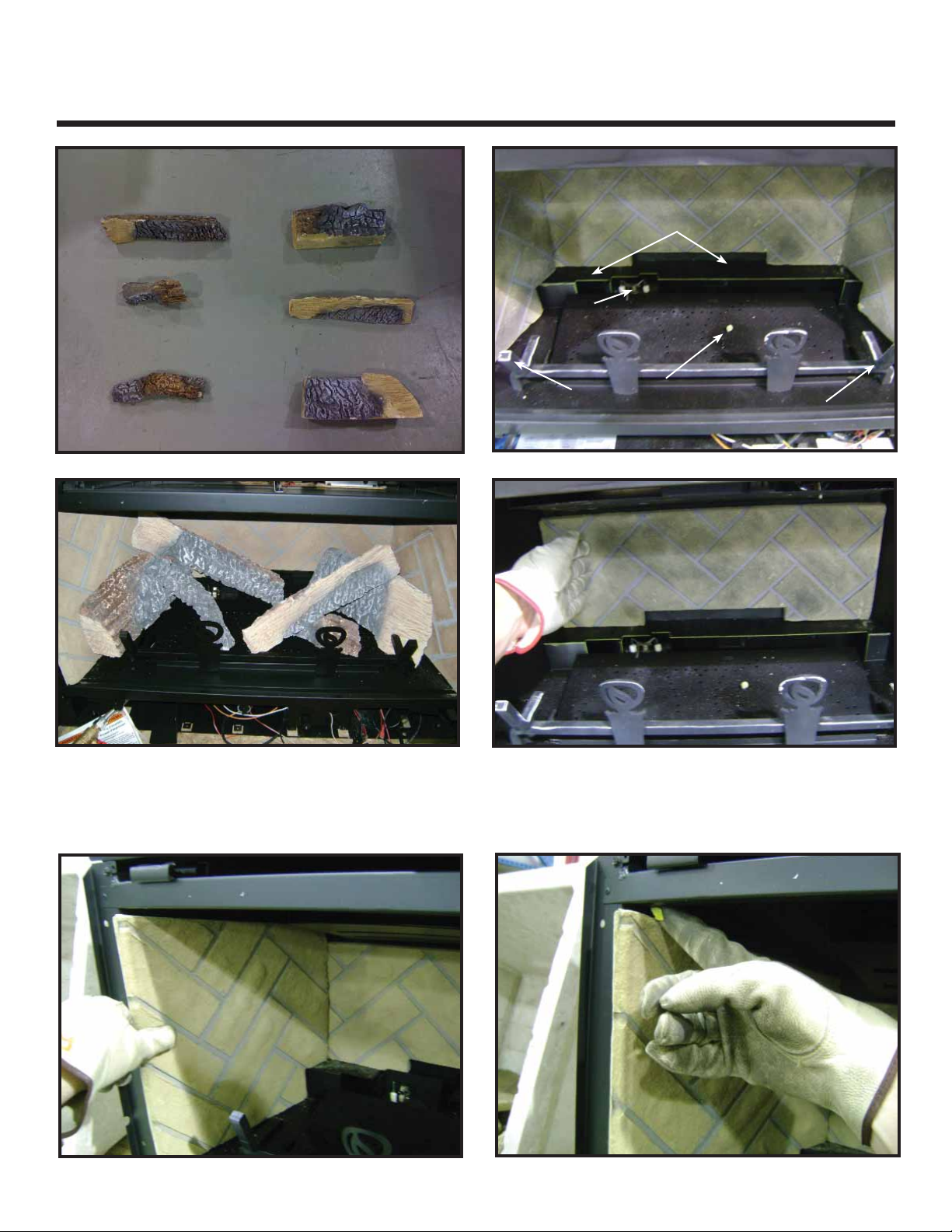
LOG PLACEMENT INSTRUCTIONS
LOG SUPPORT
PILOT
ASSEMBLY
LOG PIN
LEFT GRATE
TINE
Figure 1. Reference Points for Log Placement
RIGHT GRATE TINE
Figure 2. Refractory and Logs Installed
Figure 3. Install Back Refractory
CAUTION: Logs are fragile, handle with care. Install back refractory by placing it against the back of the fi rebox. See Figure
3. The back refractory must be held in the upright position until the side refractory is installed. Install the left side refractory
as shown in Figure 4. Bend the refractory tab down as shown in Figure 5. Repeat this step for the right refractory panel.
Figure 4. Install Side Refractory
Quadra-Fire • LOGS-QFI30 Log Instructions • 2227-935 Rev. B • 7/11
Figure 5. Bend Refractory Tab
1
Page 2
LOG CONTACTS REFRACTORY
LOG RESTS ON BURNER
LOG CONTACTS
LOG SUPPORT
LOG RESTS ON
REFRACTORY SUPPORT
LOG GROOVE
(FOR LOG #6)
NOTCH MATES WITH
RIGHT GRATE TINE
LOG PIN
MATES
WITH SLOT
LOG GROOVE
(FOR LOG #6)
NOTCH
MATE NOTCH
WITH GRATE BAR
2
3
4
FLAT SPOT FOR LOG #5
FLAT SPOT FOR LOG #5
NOTCH
FLAT SPOT FOR LOG #2
NOTCH MATES WITH LEFT
GRATE TINE
LOG CORNER ALIGNS
WITH LOG TAB
1
1
LOG CORNER ALIGNS
WITH LOG TAB
NOTCH MATES WITH LEFT
GRATE TINE
FLAT SPOT FOR LOG #2
NOTCH
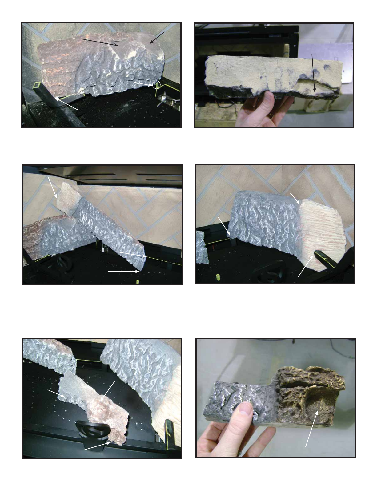
Figure 6. Placement of Log #1
Log #1 (SRV2227-703): Mate the notch located on the bottom of the log, with the left grate tine. See Figure 7. Bend the
tab located to the left of the pilot assembly into the vertical position. Rotate the back end of log clockwise until it contacts
the log tab as shown in Figure 6.
LOG CONTACTS REFRACTORY
2
LOG CONTACTS
LOG SUPPORT
LOG RESTS ON BURNER
Figure 8. Place Log #2
Log #2 (SRV2227-702): Rest left end of log on the fl at spot of Log 1. See Figure 6 and Figure 8. The left end of the log
should touch the left refractory panel. The right end rests on the burner. Push the right end back, until it touches the edge
of the log support.
Log #3 (SRV2227-701): Mate the notch with the right grate tine as shown in Fig 9. The back of the log should rest on the
log support as shown. Rotate the back end of the log clockwise until it contacts the right refractory panel.
Figure 7. Location of Notch on Log #1
LOG GROOVE
(FOR LOG #6)
LOG RESTS ON
REFRACTORY SUPPORT
3
NOTCH MATES WITH
RIGHT GRATE TINE
Figure 9. Log #3
LOG PIN
MATES
WITH SLOT
MATE NOTCH
WITH GRATE BAR
Figure 10. Log #4
LOG GROOVE
(FOR LOG #6)
4
Quadra-Fire • LOGS-QFI30 Log Instructions • 2227-935 Rev. B • 7/112
Figure 11. Log #4
NOTCH
Page 3

Log #4 (SRV2227-705): Mate the slot on the bottom of the log, shown in Figure 12, with the log pin located on the burner
SLOT
LOG END
CONTACTS
GRATE BAR
LOG END
RESTS ON
FLAT SPOT
MATE
NOTCH WITH
GRATE BAR
LOG
GROOVES
5
6
surface. The notch on the right end of the log should mate with the grate bar. See Figure 11.
LOG END
RESTS ON
FLAT SPOT
5
LOG END
CONTACTS
GRATE BAR
SLOT
Figure 12. Log #4
Log #5 (SRV2227-706): Place the left end of the log on the fl at spot of log as shown in Figure 6. The right end of log should
rest on the burner and touches the grate bar as shown in Figure 13.
6
MATE
NOTCH WITH
GRATE BAR
Figure 14. Place Log #6
Log #6 (SRV2227-704): Rest the left end of Log #6 on the burner . Mate the notch on the left end of log with the grate bar.
The log should rest on both log grooves as illustrated in Figure 9 and Figure 10.
LOG
GROOVES
Figure 13. Log #5
Quadra-Fire • LOGS-QFI30 Log Instructions • 2227-935 Rev. B • 7/11
3
 Loading...