

Page 1
R
O-T L
Tested and
Listed by
Beaverto
n
Oregon USA
OMNI-Test Laboratories, Inc
.
C
Garnet
R
1445 N. Highway
Colville, WA 99114-2008
DIRECT VENT ROOM HEATER
SAVE THESE
INSTRUCTIONS
Installation, Venting, Operation and Maintenance Manual
WARNING!
If the information in this Manual is not followed
exactly, a fire or explosion may result causing property
damage, personal injury or loss of life.
- Do not store or use gasoline or other flammable
vapors and liquids in the vicinity of this or any other
appliance.
- WHAT TO DO IF YOU SMELL GAS:
* Do not try to light any appliance.
* Do not touch any electrical switch; do not use any
phone in your building.
* Immediately call your gas supplier from a neighbor's
phone. Follow the gas supplier's instructions.
* If you cannot reach your gas supplier, call the
re department.
Installation and service must be performed by a qualied
installer, service agency or the gas supplier.
(In the Commonwealth of Massachusetts, installation
must be performed by a licensed plumber or gas tter.)
FOR YOUR SAFETY
The appliance area must be kept clear and free from
combustible materials, gasoline and other flammable
vapors and liquids.
This Manual must be used for installation of
the Garnet Gas-Fired Room Heater and retained
by the
homeowner for operating and maintenance
instructions.
WARNING!
Improper installation, adjustment, alteration, service or maintenance can cause injury or property
damage. Refer to this Manual. For assistance or
additional information, consult a qualified installer,
service agency or the gas supplier.
This appliance may be installed in an aftermarket, permanently located, Manufactured (Mobile)
Home, where not prohibited by Local Codes.
This appliance is only for use with the type of fuel
indicated on the Rating Plate. This appliance is
not
convertible for use with other gases, unless a
certified Conversion Kit is used.
This appliance may be installed as an OEM installation in manufactured home (USA only) or mobile
home and must be installed in accordance with the
manufacturer's instructions and the manufactured
home construction and safety standard, Title 24
CFR, Part 3280 or Standard for Installation in Mobile
Homes, CAN/CSA Z240 MH.
This appliance is only for use with the type(s) of
gas indicated on the rating plate. A conversion kit
is supplied with the appliance.
This Heater may be installed with a Vertical
or Horizontal Direct Vent Termination System.
250-6443B
October 7, 2003
www.quadrafire.com
Page 2
GARNET DIRECT VENT ROOM HEATER
R
Hearth & Home Technologies welcomes you to our tradition of excellence! In choosing a Quadra-Fire appliance,
you have our assurance of commitment to quality, durability, and performance.
This commitment begins with our research of the market, including ‘Voice of the Customer’ contacts, ensuring we
make products that will satisfy your needs. Our Research and Development facility then employs the world’s most
advanced technology to achieve the optimum operation of our stoves, inserts and fireplaces. And yet we are oldfashioned when it comes to craftsmanship. During manufacturing each unit is meticulously fabricated and gold
surfaces are hand-finished for lasting beauty and enjoyment. Our pledge to quality is completed as each model
undergoes a quality control inspection. Additionally, we feel it is important to offer you several finishing options and
accessories to compliment your home’s décor, individualize the use of your appliance, and provide financial options in
acquiring a quality hearth appliance. Ask your Quadra-Fire Dealer for information on these options. From design, to
fabrication, to shipping: Our guarantee of quality is more than a word, it’s Quadra-Fire tradition, and we proudly back
this tradition with a Lifetime Warranty.
Prior to installation, we ask you to take a few moments to read this manual. It has been our experience that your
overall enjoyment of your new appliance will be greatly enhanced by becoming familiar with its’ installation, operation
and maintenance requirements. We wish you and your family many years of enjoyment in the warmth and comfort of
your hearth appliance. Thank you for choosing Quadra-Fire.
With warm regards,
Alan Trusler
Senior Vice President
Dealer Channel
___________________________
Dan Henr
y
Vice President
Research & Development
___________________________
Mike Derosier
Vi
ce President
Marketing & Product Plannin
g
_________________________
Jason Olmstead
Vi
ce President &
General Manager
_________________________
Dave Fiebelkorn
Materials Manager
250-6443B October 7, 2003 Page 2
Page 3
R
GARNET DIRECT VENT ROOM HEATER
250-6443B October 7, 2003 Page 4
R
PLEASE RETAIN THIS MANUAL FOR FUTURE REFERENCE.
TABLE OF CONTENTS
Model Name:
Model Name:
GARNET DIRECT VENT ROOM HEATER
Serial Number:
Serial Number:
Date Purchased:
Date Purchased:
Dealership:
Dealership:
Dealer Phone:
Dealer Phone:
Additional Information:
Additional Information:
After completing your warranty card, attach your
After completing your warranty card, attach your
sales receipt and warranty stub here for future
sales receipt and warranty stub here for future
reference.
reference.
Dovre Garnet DV250
GARNET DIRECT VENT ROOM HEATER
GARNET DIRECT VENT ROOM HEATER
Listings and Code Approvals............................................ 4
Specifications.................................................................... 4
Notices............................................................................. 4
Safety Notices.................................................................. 5
Overview of Installation .................................................... 6
Dimensions....................................................................... 7
Clearances to Combustibles............................................. 7
LP Gas Conversion Instructions....................................... 8
Valve Regulator Replacement.......................................... 9
Thermostat Installation/Remote Control........................... 9
Log Set Installation......................................................... 10
Mineral Wool Installation ................................................ 10
Blower Kit Installation Instruction ................................... 11
VENTING
General Venting Instructions.................................... 12
Installation Methods & Notes ................................... 13
Safety Precautions for the Installer.......................... 13
Simpson-DuraVent and HTI Parts List.....................14
Installation Methods ...........................................15-19
HORIZONTAL INSTALLATION
Termination Requirements....................................... 20
Horizontal Installations....................................... 21-22
Vent Graph.............................................................. 23
VERTICAL INSTALLATION
Vertical Damper Adjustment/Flue Restrictor ........... 24
Using GS Series Pipe ........................................25-27
Roof Pitch Table...................................................... 27
Cathedral Ceiling Installation ..................................28
Class A Metal Chimney ........................................... 29
Existing Masonry Chimey................................... 30-32
Gas Line Requirements.................................................. 33
Checking Gas Inlet Pressure.......................................... 34
Leak Test........................................................................ 34
Lighting Instructions .......................................................35
High Altitude Operation Adjustment................................ 36
OPERATING PROCEDURES
Controls................................................................... 37
Normal Operating Sounds ...................................... 37
Maintenance............................................................ 37
Yearly Maintenance................................................. 38
Ignition Module and Battery Replacement .............. 39
Glass Replacement................................................. 39
Shutter Adjustment.................................................. 39
Electrical Schematic................................................ 40
Troubleshooting.............................................................. 41
Parts & Accessories & Explosed View Schematic..........42
Exploded View ............................................................... 43
Warranty ............................................................... 44
250-6443B October 7, 2003 Page 3
Page 4
GARNET DIRECT VENT ROOM HEATER
R
LISTINGS AND CODE APPROVALS
The Garnet Direct Vent Gas Appliance is listed to ANSI standard Z21.88(b)-1999/CSA 2.33b-M99 Vented Gas
F
ireplace Heaters and applicable sections of UL307b Gas Burning Heating Appliances for Manufactured Homes
and Recreational Vehicles, CAN/CGA 2.17-M91 Gas Fired Appliances for use at High Altitudes, by OMNI-Test
Laboratories, Inc., Beaverton, OR.
Natural Gas Propane
†0-2000' †0-2000'
Input Rate on "HI" (BTU/Hr) 17,500 16,000
Input Rate on "LO (Btu/Hr) 11,500 12,000
Max. Output (BTU/Hr)** 14,500 13,500
Main Burner Orifice .078 .0469
Min. Inlet Pressure (Inches W.C.) 4.5" 11"
Max. Inlet Pressure (Inches W.C.) 7.0" 14"
Manifold Pressure on "HI" (Inches W.C.) 3.5" 10"
**Max Venting, Blower ON
†This appliance is equipped for altitudes 0-2000' (0-610 M) in USA: and in Canada for altitudes of 0-4500' (0-1370 M). In
USA for Altitudes above 2000', the vent configuration, orifice, or combination of both may need to be changed. See page
36 of this manual for information on making these changes.
SPECIFICATIONS
NOTICES
Failure to follow all of the required installation procedures may result in property damage, bodily injury or
even death. This appliance must be installed in accordance with all local codes, if any (and approved by the
Commonwealth of Massachusetts); if none, follow the National Fuel Gas Code, ANSI Z223.1, or the Canadian
Installation Code, CAN/CGA 149. NOTE: Have the gas supply line installed in accordance with local building codes
by a qualified installer approved and/or licensed as required by the locality. (In the Commonwealth of Massachusetts,
installation must be performed by a licensed plumber or gas fitter.)
Manufactured Home or Mobile Home installation may occur only after the home is site located and must
conform with the Manufactured Home Construction and Safety Standard, Title 24 CFR, Part 3280, or, when such a
standard is not applicable, the Standard for Manufactured Home Installations, ANSI/NCSBCS A225.1, or Standard
for Gas Equipped Recreational Vehicles and Mobile Housing, CSA Z240.4.
When installed, the appliance must be electrically grounded in accordance with local codes or, in the absence
of local codes, with the National Electrical Code, ANSI/NFPA 70, or the Canadian Electrical Code, CSA C22.1.
The Garnet is manufactured to operate on Natural Gas (NG), it is field convertible to Liquid Propane (LP) using
the manufacturer's conversion kit.
All exhaust gases must be vented outside the structure of the living-area. Combustion air is drawn from outside
the living-area structure.
Notify your insurance company prior to connecting gas to this fireplace.
Installation requirements diagrammed and explained in this manual are grouped into segments for ease of
procedure. While these requirements must be met fully, the order of installation may be subject to the procedure best
suited for your specific placement of the fireplace.
NOTE: Illustrations throughout these instructions reflect typical installations and are for design purposes
only. Actual installation may vary slightly due to individual design preferences. However, minimum and
maximum clearances must be maintained at all times.
The illustrations and diagrams used throughout these installation instructions are not drawn to scale.
250-6443B October 7, 2003 Page 4
Page 5
R
GARNET DIRECT VENT ROOM HEATER
250-6443B October 7, 2003 Page 6
R
GARNET DIRECT VENT ROOM HEATER
SAFETY NOTICES
! Due to high temperatures, the appliance should be located
out of traffic and away from furniture and draperies.
! Do not place clothing or other flammable items on or near
the appliance at any time. Due to thermostatic control, the
possibility exists for the appliance to turn on, igniting any
items on or near it.
! Children and adults should be alerted to the hazards of
high surface temperature and should stay away to avoid
burns or clothing ignition.
! Young children should be carefully supervised when they
are in the same room as the appliance.
! Any safety screen or guard removed for servicing an
appliance must be replaced prior to operating the
appliance.
Installation and repair should be performed by a
qualified, and/or where required by state and local codes,
licensed installer/service technician. (In the Commonwealth of
Massachusetts, installation must be performed by a licensed
plumber or gas fitter.) The appliance should be inspected before
use and at least annually by a professional service person.
More frequent cleaning may be required due to excessive lint
from carpeting, bedding material, et cetera. It is imperative that
control compartments, burners and circulating air passagways
of the appliance be kept clean.
Strict adherence to the instructions in this manual
must be followed. Improper installation will void the warranty
and safety listing.
This appliance is manufactured to operate on natural
gas (NG). It is field convertible to propane (LP) with the
manufacturers’ conversion kit. Burning incorrect fuel voids the
warranty and safety listing and may cause an extreme safety
hazard.
Contact local building officials to obtain a permit and
information on installation restrictions or requirements in your
locale. It is also important to notify your homeowner’s insurance
company of the installation of this appliance as well.
Do not use this appliance if any part has been under
water. Immediately call a qualified service technician to inspect
the appliance and to replace any part of the control system and
any gas control which has been under water.
Do not store or use gasoline or other flammable liquids
in the vicinity of the appliance.
If the flame becomes sooty, dark orange in color, or
extremely tall, DO NOT operate the appliance. Contact your
dealer and arrange for servicing immediately.
DO NOT op
erate
the
appliance if it is
not
operating
properly in any manner. Contact your dealer for assistance.
Open viewing glass for servicing only.
Operate the appliance in accordance with the
instructions contained in this manual.
If the main burners do not start correctly, turn the gas
off at the gas control valve and contact your dealer for service.
Do not operate with glass cracked or broken.
This unit is not for use with solid fuel.
DO NOT place anything inside the firebox (other than
the included logs and lava rock.
If the logs become damaged refer to the Parts and
Accessories page of this manual for replacement.
Instruct everyone in the house how to shut off the gas
to the appliance and also at the main gas shut-off valve. The
main gas shut-off valve is usually located next to the gas meter
or propane tank and requires a wrench to shut off.
Use the built-in electronic igniter to light the appliance.
DO NOT use matches or any other external device.
DO NOT remove, replace, modify or substitute any
part of the appliance unless instructions are given in this
manual. All other work must be done by a trained technician.
Allow the appliance to cool before carrying out any
maintenance or cleaning.
The pilot flame must contact the thermopile and
thermocouple. If it does not, turn the gas control valve to “OFF”
and call your Dealer.
DO NOT THROW THIS MANUAL AWAY. IMPORTANT
OPERATING AND MAINTENANCE INSTRUCTIONS ARE
INCLUDED.
WARNING!
Improper installation, adjustment, alteration, service or
maintenance can cause injury or property damage. Refer to
this manual for correct installation and operational procedures.
For assistance or additional information consult a qualified
installer, service agency, or the gas supplier.
CAUTION!
Do not operate appliance with the glass front removed,
cracked or broken. Only the door certified for use
with the appliance shall be used. Replacement of
the glass should be done by a licensed or qualified
service person. Do not strike the glass.
This appliance is equipped with a three pronged
(grounding) plug for your protection against shock
hazard and should be plugged directly into a
properly grounded three prong receptacle. Do not
cut or remove the grounding prong from this plug.
WARNING!
250-6443B October 7, 2003 Page 5
Page 6

GARNET DIRECT VENT ROOM HEATER
R
OVERVIEW OF INSTALLATION TO OPERATION
• Familiarize yourself with this Owner's Manual and the Safety Notices located in this manual,
and posted on the gas appliance.
• Remove and unpack the following components:
The Log Set is taped to the top of the stove.
• Inside the firebox will be the Component Bag.
• Unbolt the appliance from the pallet.
• Remove the top and then the face of the stove. The face is removed by lifting straight up.
• Remove the glass door by opening the latches located on both the left and right sides at the
top of the glass. Pull towards you and separate latch from notches. Lift the glass out of the
two notches at its base and carefully set aside.
• Convert to LP if necessary. (Use Conversion Kit included with appliance).
• Install Blower if purchased. (Part #844-9370).
• Finalize your installation decisions and requirements:
• Refer to Dimensions on page 7.
• Refer to Clearances to Combustibles on page 7.
• Refer to Horizontal and Vertical termination requirements on pages 20-32.
• Install damper if necessary for your venting plans, see page 24. (In the Commonwealth
of Massachusetts, the word damper shall be replaced with the words flue restrictor.)
• Refer to Vent Kits pertinent to your installation on page 14.
• Contact your local building inspector for code requirements in your area.
• Run thermostat lines to TH & TPTH connectors on valve, if applicable, see page 9.
• Set unit in place and install venting per your installation requirements.
• Install Log Set and lava rock. See instructions on page 10 of this manual.
• Connect the gas line. See page 33.
• Plug in blower, if purchased.
• Leak test gas line to manual shut-off valve. See page 34.
• Re-attach the glass door.
• Re-attach the face.
• Follow Lighting Instructions, page 35, to light the appliance. (A copy is attached to a beaded
chain on the lower right hand side of the appliance).
• Adjust gas control knob to "ON" (Following Lighting Instructions page 35).
• Set Thermostat or turn control panel switch to the "ON" position.
• Check flames and adjust shutter position, if necessary. See page 39.
• Familiarize yourself with the maintenance requirements of the stove. See pages 37 & 38.
• Familiarize yourself with the Troubleshooting section of this manual, page 41.
250-6443B October 7, 2003 Page 6
Page 7
R
GARNET DIRECT VENT ROOM HEATER
250-6443B October 7, 2003 Page 8
R
17-7/8"
(454mm)
13-1/4"
(337mm)
22-1/8"
(562mm)
17-7/8"
(454mm)
17-1/4"
(438mm)
16-7/8"
(429mm)
13-3/4"
(349mm)
C
L
16-5/8"
(422mm)
5-1/2"
(140mm)
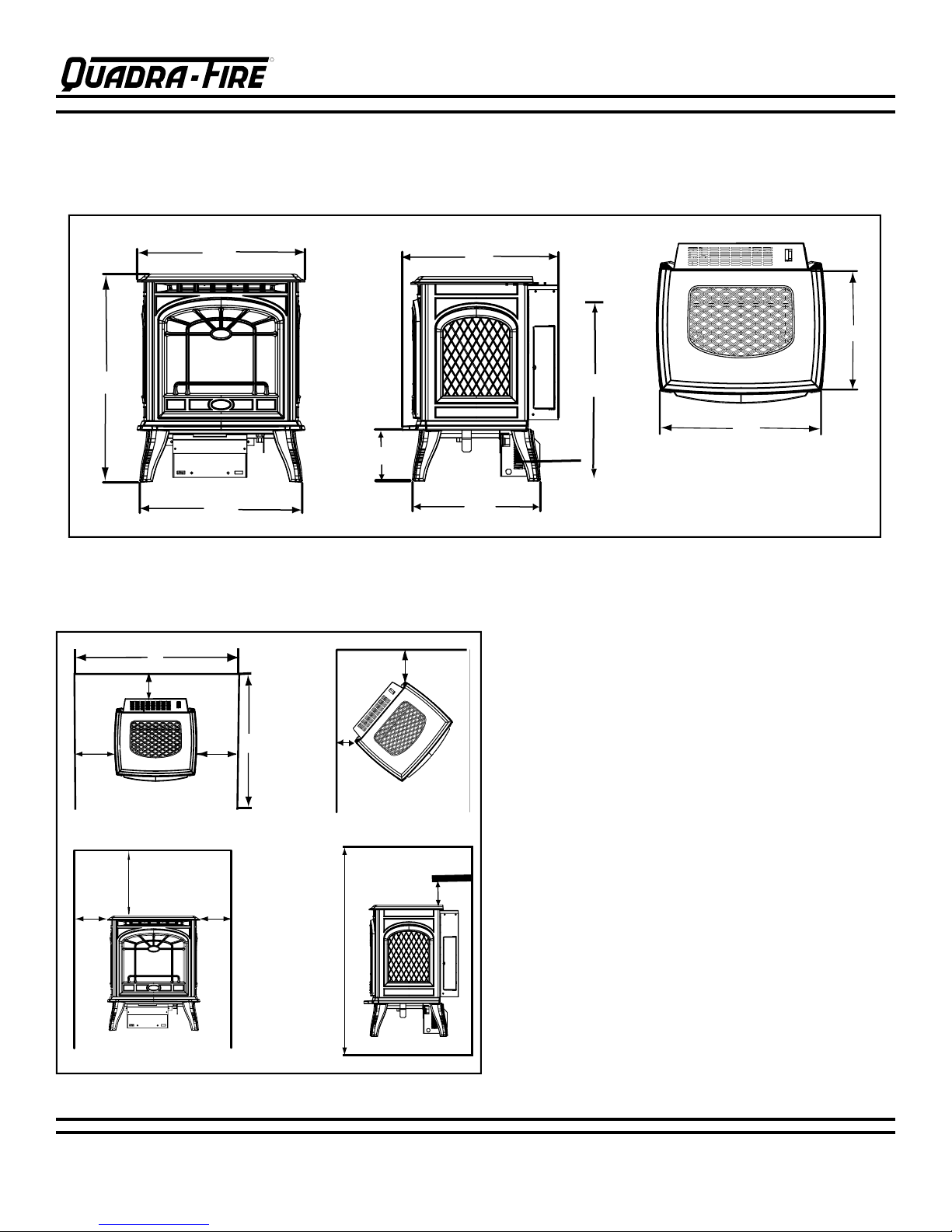
NOTE: Diagrams show gas stove equipped with optional Blower, Part #844-9370.
GARNET DIRECT VENT ROOM HEATER
DIMENSIONS
CLEARANCES TO COMBUSTIBLES
Minimum clearances required from combustible construction for all appliance surfaces
F
B
A
A
E
3 1/2"
1
C
1"
C
2
Right
Left
"A" measurement is from
stove top, not side
G -Alcove
A
250-6443B October 7, 2003 Page 7
A
D
H
HEARTH: A non-combustible hearth pad is not required.
However, the oor beneath the stove must be stable,
level, and strong enough to support the stove without a
tipping hazard. Wood ooring, ceramic tile, brick hearths,
or high pressure laminate ooring applied directly over
the sub-ooring material meet this requirement. If the
appliance is installed over carpet or combustible tile (vinyl
tile), a metal or wood panel extending the full width and
depth of the appliance must be installed.
A. Side of stove top to side wall 6" (152mm)
B. Rear of stove to back wall 0" (0cm)
1
C
. Corner of stove top to side wall-Left 1" (25.4mm)
2
C
. Corner of stove top to side wall-Right 3-1/2" (88.9mm)
(
for valve clearance)
D. Minimum alcove height 43" (1092mm)
E. Maximum alcove depth 36" (914mm)
F. Minimum alcove width 30" (762mm)
G. Top of Stove to alcove ceiling 20-7/8" (530mm)
H. Mantle Clearance 21-1/2" (546mm)
NOTE: Flooring beneath appliance may reach 90 degrees
plus room ambient temperature. Check with flooring
manufacturer for maximum temperature allowed on
ooring surfaces.
Page 8
GARNET DIRECT VENT ROOM HEATER
R
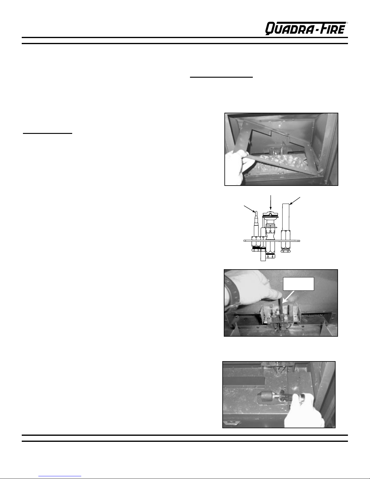
MILLIVOT GENERATOR
PILOT HOOD
THERMOCOUPLE
5/32" Allen
wrench
LP CONVERSION INSTRUCTIONS
NOTE: Have the gas supply line installed in accordance
with local building codes by a qualified installer
approved and/or licensed as required by the locality.
(In the Commonwealth of Massachusettes installation
must be performed by a licensed plumber or gas
TOOLS REQUIRED:
helpful) or slotted screwdriver or Torx TH20; #2
Phillips bit; 5/32" Allen wrench; 5/8" open end
wrench.
tter.)
FIG. 1
KIT CONTENTS:
Replacement orice; replacement
pilot injector; valve regulator; conversion label.
1
. Remove front (if installed), glass, and logs (if
installed).
2. Remove log/burner pan: First remove screws then lift
side of pan vertically and pull out of rebox. (Fig. 1)
3. Remove burner: Loosen shutter set screw and slide
shutter all the way to the right (closed). Lift left side of
burner and slide to the left.
4. Pull off pilot hood and set aside. (Fig. 2)
5. Use a 5/32" Allen wrench to remove the pilot injector.
(Fig. 3)
6.
Replace pilot injector with the appropriate size injector
supplied with the stove (#35 for Propane, #62 for Natural
Gas).
7. Replace pilot hood, snapping into position.
8.
Remove main burner orice using a 5/8" wrench. (Fig. 4)
9. Replace orice with the proper size as indicated below
for your gas type and venting.
PROPANE NATURAL GAS
.0469 .078
Power drill (a 90° handle is
FIG. 2
FIG. 3
5/32" Allen Wrench
FIG. 4
10. Reinstall burner. Slide burner neck into shutter and
over orice. Install log/burner pan using the three
screws removed.
See page 9 for Valve Regulator Replacement.
250-6443B October 7, 2003 Page 8
Page 9
R
GARNET DIRECT VENT ROOM HEATER
250-6443B October 7, 2003 Page 10
R
A
B
C
E
D
F
GARNET DIRECT VENT ROOM HEATER
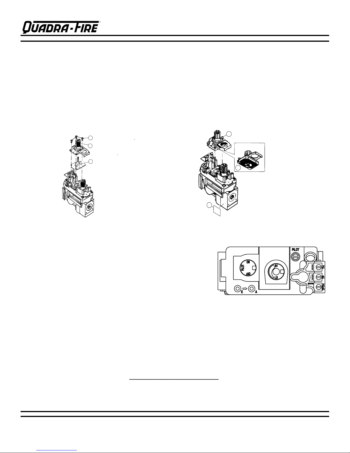
LP CONVERSION (cont'd.)
Valve Regulator Replacement
1. Turn control knob to the OFF position, ensure that gas supply to the valve has been turned off.
2. Using a Torx TH20, or slotted screwdriver, remove the (A) three pressure regulator mounting screws, (B)
pressure regulator tower, and (C) diaphragm.
3. Ensure that the (D) rubber gasket is properly positioned and install the new HI/LO pressure regulator
assembly to the valve using the (E) new screws supplied with the kit. Tighten screws securely. (Reference
torque = 25 in/lb)
4. Install the enclosed (F) identication label to the valve body where it can be seen.
5. Fill out the Conversion Label and attach to the valve cover.
Mounting Screws
Pressure Regulator Tower
Diaphragm
New Screws provided with kit
Rubber Gasket
Identification Label
THERMOSTAT INSTALLATION
A thermostat may be installed to regulate the Garnet. It is important
to use a thermostat designed for millivolt operation. Do not connect
the heater to a thermostat serving any other appliance. Bedroom
installation in Canada requires this heater to be connected to a
thermostat.
Connect the thermostat wires to the outside valve terminals labeled
"TH" and "TPTH". Turn the manual switch on the control panel to
"OFF".
REMOTE CONTROL
A remote control or a wall switch may be wired to the thermostat terminals. Contact your Dealer for details.
Manual Thermostat Part Number 812-3760
Anticipator Setting 1.2
Programmable Thermostat Part Number 811-0520
Recommended Maximum Lead Length (2 wire) when using wall thermostat/switch:
Wire Size Maximum Length
16 gauge 65 Feet
18 gauge 40 feet
20 gauge 25 feet
22 gauge 18 feet
250-6443B October 7, 2003 Page 9
Page 10
GARNET DIRECT VENT ROOM HEATER
R
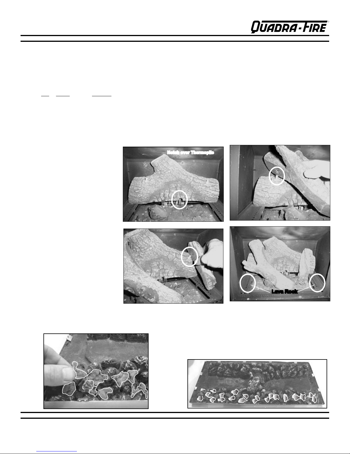
LOG SET INSTALLATION
Complete Set Part 842-4980
The three piece log set is packed in the components
box and consists of the following:
Qty Name Diagram
1 Rear Log Fig. 1
1 Left Twig Fig. 2
1 Right Twig Fig. 3
1 Lava Rock Fig. 4
Installation:
1. Place the notch in the Rear Log
over the Thermopile. Push the
log all the way to the rear of the
firebox (Fig. 1).
2. Place the hole in the bottom of the
Left Twig over the left pin in the
Rear Log (Fig. 2).
3. Place the hole in the bottom of the
Right Twig over the right pin in the
Rear Log. Lay the end of the twig
in ember bed (Fig. 3).
4. A complete assembled Log Set is
shown in Fig. 4.
5. The lava rock supplied with the
stove can be poured in the trays
along the left and right sides of
the burner pan.
NOTE: Do not pour any of the lava
rock onto the burner (Fig.4).
FIG. 1
While breakable, the logs do not become fragile until after
the stove is burned and they have cured. After curing, any
handling must be done with care as breakage may occur
easily.
PLEASE NOTE: Logs have been designed to work
specifically with the burner of the Garnet. Exact
placement will ensure proper operation of your gas
appliance and reduce sooting.
Notch over Thermopile
FIG. 2
FIG. 3
FIG. 4
Apply dime size pieces sparingly along front edge of burner. Do not completely block ports.
250-6443B October 7, 2003 Page 10
MINERAL WOOL INSTALLATION
COMPLETE INSTALLATION
L
ava Rock
Page 11
R
GARNET DIRECT VENT ROOM HEATER
250-6443B October 7, 2003 Page 12
R
GARNET DIRECT VENT ROOM HEATER
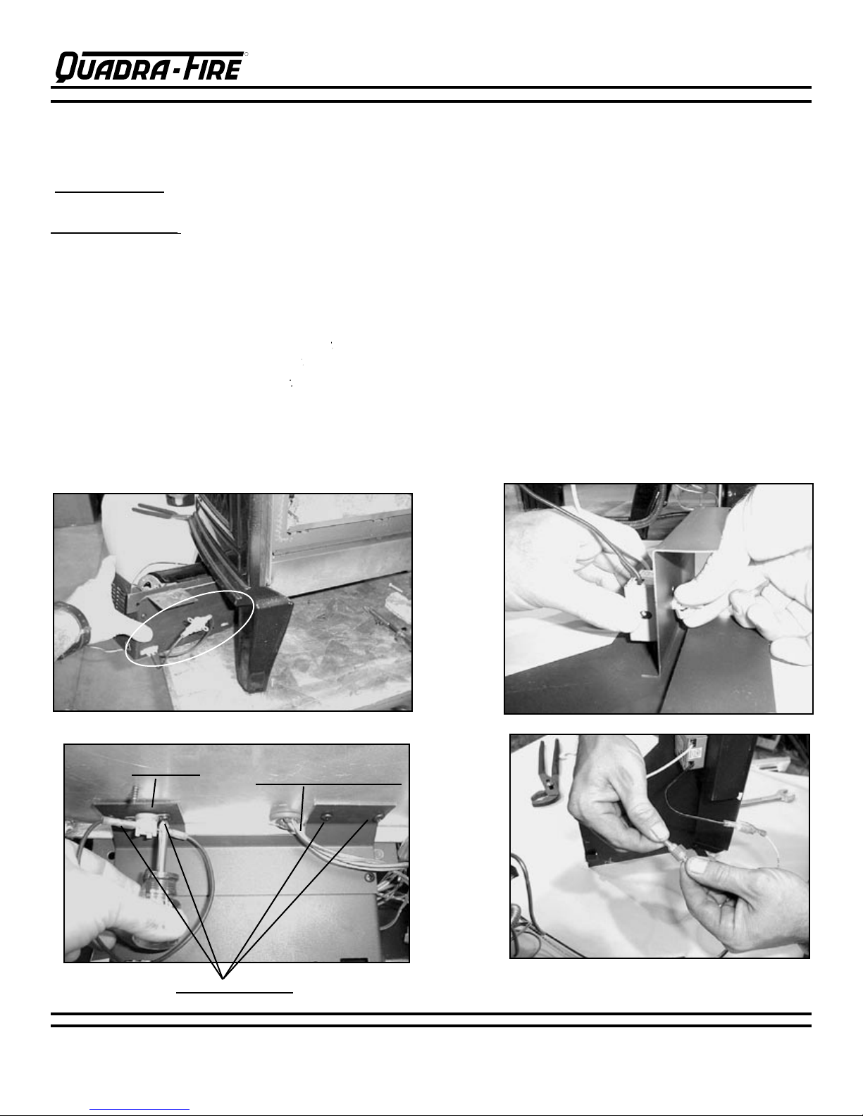
BLOWER INSTALLATION
PART #844-9370
KIT CONTENTS: Blower motor, housing and snap disc assembly; rheostat (speed control); rheostat nut; knob; screws;
knob position label.
TOOLS REQUIRED: Short #2 Philips head screwdriver; 11/16" wrench.
The blower is held in place using 4-#6 screws. The scews are already installed in the bottom of the re box.
1. Remove the (4) screws from the rebox and slide the blower into place from the left side of the stove. (Fig. 1)
Notice the locations of the pilot assembly tubes and wires. The pilot tubes and wires may need to be moved to prevent
scraping the blower housing. (Fig. 2)
2. Re-use the (4) screws removed from the bottom of the rebox, to install the blower. Install the 2 screws on the right
rst, then use the other 2 screws to hold the snap disc in place and support the left side of the blower. (Fig. 2)
3. Remove the valve access panel by removing the (3) screws that secure it to the right side of stove and sliding it out.
4. Attach the rheostat to valve access cover and tighten with 11/16 wrench. Attach label showing knob positions on valve
cover. Install the knob on the rheostat. (Fig. 3)
5. Connect the black and white wires from the blower to the rheostat wires. (Fig. 4)
6. Re-install the valve access cover.
7. Route power cord away from unit. DO NOT route the power cord under or in front of the stove.
FIG. 1
FIG. 2
Snap Disc
FIG. 3
FIG. 4
Pilot Tubes and Wires
Mounting Screws
250-6443B October 7, 2003 Page 11
Page 12
GARNET DIRECT VENT ROOM HEATER
R
GENERAL VENTING INSTRUCTIONS
PLEASE NOTE: In order to comply with applicable
codes and product warranties, only Simpson DuraVent (SDV), Hearth & Home Technologies (HTI)
venting components, or Security Chimney's Secure
Vent Chimney System may be used. DO NOT USE
FIELD-FABRICATED VENTING COMPONENTS. The
Garnet is approved to be vented either horizontally,
through the side wall, or vertically, through the roof.
You may vent through a Class A or masonry chimney
if a Simpson Dura-Vent adapter is used (for USA
installations only). Only use Simpson Dura-Vent, or
HTI components labeled and listed on page 14.
This appliance is a direct vent heater. All combustion
air must come directly from the outside of the building.
The vent pipe for this unit consists of an inner and an
outer pipe. The inner pipe carries the stove exhaust
out of the system, and the outer pipe brings fresh
combustion air into the stove.
! A wall thimble is required when the venting
passes through a wall.
! A support box or firestop is required when the
venting passes through a ceiling.
! Roof flashing and a storm collar are required when
venting passes through the roof. Follow instructions
provided with the venting for installation of these items.
IMPORTANT: Read all these instructions carefully
before starting the installation. Failure to follow
instructions may create a fire or other safety
hazard, and will void the warranty. Be sure to
follow these installation instructions for venting
and clearance to combustible requirements, which
may vary from one installation to another. Do
not extend the venting system in excess of
the distance prescribed in these manufacturer’s
installation instructions. This gas appliance must
not be connected to a chimney flue serving a
separate solid-fuel burning appliance.
INSTALLATION PRECAUTIONS:
The Quadra-Fire Garnet is an engineered product
that has been designed and tested. The warranty will
be voided, and serious fire, health, or other safety
hazards may result from any of the following actions:
Installation of any damaged venting component,
unauthorized modification of the venting system,
installation of any component part not approved by
Hearth & Home Technologies, or installation other than
as instructed by these instructions. Consult your local
building codes before beginning this installation.
WARNING: Always maintain the required clearances (air
space) to nearby combustibles to avoid creating a fire
hazard. Do not fill air space with insulation. Minimum
clearance between vent pipes and combustible surfaces is
1” (2.5cm). Be sure to check the horizontal vent termination
clearance requirements from decks, windows, soffits, gas
regulators, air supply inlets and public walkways, as
specified on page 20 of these installation instructions, the
vertical termination requirements on page 18, 19 and 27,
and local building codes.
The gas heater and vent system must be vented
directly to the outside of the building, and never be
attached to a chimney serving a separate solid fuel or
gas-burning appliance. This direct vent gas fireplace
must use its own separate vent system. Common vent
systems are prohibited.
250-6443B October 7, 2003 Page 12
Page 13
R
GARNET DIRECT VENT ROOM HEATER
250-6443B October 7, 2003 Page 14
R
INSTALLATION METHODS & NOTES
GARNET DIRECT VENT ROOM HEATER
Four types of direct vent system installations are
approved for use with the Garnet.
1. Horizontal Termination (Fig. 1, page 15)
2. Vertical Termination (Fig. 2, page 18)
3. Into a Class A Metal Chimney (Fig. 3, page 18)
USA installations only
4. Into a Masonry Chimney (Fig. 4, page 19) USA
installations only
Do not connect to a chimney serving a separate solidfuel burning appliance.
In each of these installation methods, it is very important
to maintain a balance between the combustion air
intake and the flue gas exhaust venting system.
Note: Certain limitations as to vent and vertical
termination configurations apply, and must be strictly
adhered to.
When planning your installation, it is necessary to
select the proper length of vent pipe for your particular
requirements.
1. For installations with any horizontal vent run or
horizontal termination, refer to the Vent Graph on page
23. This graph will show the relationship between
vertical and horizontal side wall venting, and help you
to determine the amount of vertical rise necessary for
“vertical-to-horizontal” type installations.
each floor level. If an offset is needed in the attic,
additional pipe and elbows will be required. When
determining the position of the stove, be sure to
adhere to minimum clearance to combustibles to the
appliance itself. (See page 7, Minimum Clearances to
Combustibles.)
3. When installing this appliance into an existing
masonry chimney, it is important to carefully measure
the length of flex needed to reach from the appliance
outlet to the termination cap. If the flex length is too
short, a flex coupler will be needed to attach an
additional length of flex liner to make up the difference.
If the flex length is too long, the liner could sag below
the appliance outlet, which could result in an airflow
restriction causing flow reversal or flame lift.
SAFETY PRECAUTIONS FOR THE INSTALLER
Wear gloves and safety glasses for protection when
installing this stove. Exercise extreme caution when
using ladders or on rooftops around power lines.
Be aware of electrical wiring locations in walls and
ceilings.
NOTE: Be sure to take into consideration the wall
thickness when calculating your venting needs.
2. To determine the length of pipe required for vertical
installations, measure the distance from the stove flue
outlet to the ceiling, the ceiling thickness, the vertical
rise in an attic or second story, and allow for sufficient
vent height above the roofline. Refer to the vertical
vent termination tables on page 27 for this information.
For two-story applications, fire stops are required at
250-6443B October 7, 2003 Page 13
Page 14
GARNET DIRECT VENT ROOM HEATER
R
SIMPSON DURA-VENT and HTI PARTS LIST
Termination Caps & Snorkels:
991 High Wind Vertical Termination Cap
985 High Wind Horizontal Termination Cap
983 Vertical Termination
981 Snorkel Termination (36”)
982 Snorkel Termination (14”)
950 Vinyl Siding Standoff (VSS)
Flashing:
941 Cathedral Ceiling Support Box
943 Flashing, 0/12 to 6/12 Roof Pitch
943S Flashing, 7/12 to 12/12 Roof Pitch
943F Flashing, Flat Roof
Support Boxes/Thimbles:
940 Round Ceiling Support/Wall Thimble Cover
941 Cathedral Ceiling Support Box
942 Wall Thimble
Pipe:
908 6” Pipe Length, Galv.
908B 6” Pipe Length, Black
907 9” Pipe Length, Galv
907B 9” Pipe Length, Black
906 12” Pipe Length, Galv.
906B 12” Pipe Length, Black
904 24” Pipe Length, Galv.
904B 24” Pipe Length, Black
903 36” Pipe Length, Galv.
903B 36” Pipe Length, Black
902 48” Pipe Length, Galv.
902B 48” Pipe Length, Black
911 11” -14 5/8” Pipe, Adj. Galv.
911B 11” -14 5/8” Pipe, Adj. Black.
912 12” - 17” Pipe, Adj. Galv.
912B 12” - 17” Pipe, Adj. Black.
917 17” -24” Pipe, Adj. Galv.
917B 17” -24” Pipe, Adj. Black.
945 45° Elbow, Galv.
945B 45° Elbow, Black
990 90° Elbow, Galv.
990B 90° Elbow, Black
Misc.
953 Storm Collar
963 Ceiling Firestop
988 Wall Strap
9546 Attic Insulation Shield
923GK Chimney Liner Termination Kit
923GCL
909B Retrot Adj. Chimney Connector Retrot
Chimney Connector Plate
Decorative Trim Kits
Co-axial / Co-lineal Appliance Connector
3951 Round Celing Support; Wall Thimble Trim Kit,
Polished Brass
3960
Cathedral Ceiling Support Trim Kit, Polished Brass
SDV KITS
970A Standard Termination Kit includes 1 each of:
990B, 940, & 985. See Note below.
971HW Standard Termination Kit includes 1 each of:
990B, 940, 985, 904B, 911B
973 Vertical Termination Kit includes 1 each of:
NOTE: Straight pipe lengths are needed to complete
installation; the black 45
943, 953, 991 (support box NOT included)
° elbow is NOT included in kit.
HTI'S VENT PARTS LIST
HHW2 841-0670 Horizontal High Wind Cap
(recommended for optimal perfor-
mance)
HHW2K 844-4490 Horizontal Kit (One 90° Black
Elbow, Wall Thimble, 24” Black Pipe,
11”-14-5/8” Adjustable Vent, HHW2
Termination Cap)
RHVK 844-8920 Snorkel Kit #844-8920 (with Dura Vent part #'s 911B and 940)
SECURITY CHIMNEY'S SECURE VENT CHIMNEY SYSTEM
& AMERIVENT DIRECT VENTING COMPONENTS
Your Quadra-Fire Garnet has been approved with Security Chimney's Secure Vent Chimney System and Amerivent Direct
Venting Components. All the required certification tests have been successfully completed with OMNI-Test Laboratories,
Inc. Please contact your local dealer and they will advise you of the required parts needed for your installation. It is required
to use High Temperature RTV Sealant at the inner and outer joint connection of the first section to the supplied listed direct
vent starter section.
250-6443B October 7, 2003 Page 14
Page 15

R
GARNET DIRECT VENT ROOM HEATER
250-6443B October 7, 2003 Page 16
R
90 DEG. ELBOW
PIPE LENGT
H
PIPE LENGT
H
WALL
THIMBLE
PART #942
center line
WALL THIMBLE COVER
PART #940
HTI Vent HHW2 Part #841-0670
(recommended for optimum
performance)
OR
HORIZONT
AL TERMINATION
CAP, Simpson Dura Vent Part
#985
HTI Vent HHW2 Part #841-0670
(recommended for optimum
performance)
OR
HORIZONTAL TERMINATION
CAP, Simpson Dura Vent Part
center line
16-5/8"
WALL THIMBLE
PART
#942
WALL THIMBLE COVER
PART #940
45° Elbow
1" Clearance from stove
corner to combustible wall
.
3-1/2" Clearance from
stove corner to combustible
wall (for valve access on
right side.)
Wall Thimble Part #942
INSTALLATION METHODS
FIG. 1 - HORIZONTAL TERMINATION
Refer to pages 20-22 for installation instructions and requirements.
Type A - Up & Out Installation
GARNET DIRECT VENT ROOM HEATER
250-6443B October 7, 2003 Page 15
Type B - Straight Out Installation
Type C - 45° Elbow in Corner
Installation
Page 16

GARNET DIRECT VENT ROOM HEATER
R
3/4
3/4
3/4
SLIM LINE WALL THIMBLE
Part #844-9550
BEFORE YOU BEGIN:
Venting conguration will determine which Trim Ring you
use in your installation. Review Figures A, B and C on
Page 17. Figures A and B can use either Trim Ring, while
Figure C REQUIRES the Ventilated Trim Ring.
ASSEMBLING SLIM LINE TRIM RING
and HEAT SHIELD
1. Choose the appropriate Trim Ring for your installation.
Lay on at surface and bend up the 6 welded brackets into
a 90 degree position. The brackets along the outer edge of
the ring are for locating the ring in the center of the hole.
See Fig. 1.
2. The Heat Shield is shipped at and must be hand bent
into a half circle before attaching to Trim Ring. Bend Heat
Shield. See Fig. 2.
Note: Wear leather gloves when bending the Heat Shield
to prevent injury.
Fig. 1 Solid Trim Ring Shown
Fig. 2 Bending Heat Shield
3. Attach the Heat Shield to the Trim Ring with the four
screws provided. Screws go through the Heat Shield and
into the brackets on the Trim Ring. See Fig. 3.
INSTALLING SLIM LINE TRIM RING
and HEAT SHIELD
1. Measure from oor to center line of the vent pipe. Cut
out a 9-1/2" hole in the wall. Hold the Trim Ring/Heat Shield
Assembly in place and place a mark on the shield with a
black marker where it protrudes through the exterior wall.
See Fig. A on Page 17.
2. Use that mark as a guide to trim off excess Heat Shield
with a pair of sheet metal shears.
Note: When installing the Trim Ring/Heat Shield assembly
make sure the Trim Ring is centered in the hole and that
the shield is above the pipe. There must be a minimum of
3/4" minimum clearance maintained to combustibles from
the top of the Heat Shield. See Fig. 4.
3.
Ensure that framing on the inside of the wall is a minimum
inner framing diameter of 10" x 10".
Fig. 3 Ventilated Trim Ring Shown
Fig. 4
3/4"
3/4"
3/4"
4. The four Trim Ring mounting screws provided should be
replaced with appropriate fasteners for stucco, brick, concrete,
or other types of sidings.
250-6443B October 7, 2003 Page 16
Maintain minimum 3/4" clearance to
combustibles from top of shield.
Page 17

R
GARNET DIRECT VENT ROOM HEATER
250-6443B October 7, 2003 Page 18
R
HTI Vent HHW2 Part
#841-0670
(recommended for
optimum performance
)
OR
HORIZONT
AL
TERMINATION CAP,
Simpson Dura Vent
Part #985
center line
HEAT SHIELD
OVER TOP HALF
OF PIPE
TRIM RING
VENTILATED
REQUIRED
Minimum of 6"
of pipe through
the wall
INTERIOR
WALL
WALL
THIMBLE
90 DEG. ELBOW
PIPE LENGTH
PIPE LENGTH
center line
TRIM RING
SOLID OR
VENTILATED
HTI Vent HHW2 Part #841-0670
(recommended for optimum
performance)
OR
HORIZONT
AL TERMINATION
CAP, Simpson Dura Vent Part
#985
Place mark where protrudes
through exterior wall to cut off
Use HEAT SHIELD or WALL THIMBLE
45° Elbow
1" Clearance from stove
corner to combustible wall.
3-1/2" Clearance from
stove corner to combustible
wall (for valve access on
right side.)
HEAT SHIELD
OVER PIPE
TRIM RING
SOLID OR VENTILATED
NOTE: Wall Thimble removed
to show Heat Shield
SLIM LINE WALL THIMBLE (cont'd.)
Note: When installing the Garnet to a rear
wall in the Zero Clearance conguration
remove the two heat shield knock-outs on
the rear of the stove. See Fig. 5 Below.
FIG. 5
GARNET DIRECT VENT ROOM HEATER
FIG. A 90 DEGREE ELBOW
FIG. C ZERO CLEARANCE
250-6443B October 7, 2003 Page 17
FIG. B 45 DEGREE ELBOW
Page 18

GARNET DIRECT VENT ROOM HEATER
R
VERTICAL
TERMINATION
CAP
STORM
COLLAR
FLASHING
FIRESTOP
PIPE
LENGTH
SUPPORT
BOX
TERMINATION
CAP
PA
RT #991
EXISTING
METAL
CHIMNEY
SYSTEM
TO
P
ADAPTOR
FLASHING
4" FLEX PIPE
RETRO CONNECTOR
DIRECT VENT PIPE
INSTALLATION METHODS (cont'd.)
FIG. 2 - VERTICAL TERMINATION
Refer to pages 25-27 for installation instructions
and requirements.
On vertical terminations use only Dura-vent Part #991.
Figure 2
FIG. 3 - CLASS A METAL CHIMNEY
(USA only)
Refer to page 29 for installation instructions
and requirements.
Figure 3
250-6443B October 7, 2003 Page 18
Page 19

R
GARNET DIRECT VENT ROOM HEATER
250-6443B October 7, 2003 Page 20
R
imney Line
r
mination Ca
p
art #923G
K
Co-Axial to
Co-Linear
Connector
3" Flex Liner
Pipe Length
Optional
Showing (2)
30 ft
Sections of
imney Line
r
mination Ca
p
art #923G
K
Co-Axial to Co-
Linear Connector
Part #923GCL
30 ft of 3" Flex Liner
Exhaust Section
Pipe Length
Optional
4 ft of 3" Flex Liner
Air Intake Section"
The chimney must be
sealed from
the 4 ft
section to termination
using a smoke
shelf
or a damper. The seal
should be 6" below
the end of the 4 ft Air
Intake section.
This section of the
chimney must be
sealed
TERMINATION
CAP
PART #99
1
FLASHING
"
TOP ADAPTO
R
RETRO
CONNECTO
R
90 DEG.
ELBO
W
DIRECT
Chimney Liner
ermination Ca
p
art #923G
K
30 ft of 3" Flex
Liner
4 ft of 3" Flex Liner
Air Intake Section"
Chimney mus t be
seal ed from 4 f t
section to termination
using a smoke shelf
or a
damper. Seal
should be 6" below
end of 4 ft Air Intake
section.
This section of the
chimney must be sealed
Co-Axial to Co-Linear Connector
DAMPER MUST BE INSTALLED FOR THIS APPLICATION (SEE PAGE 24)
Alcove Clearance to
Combustibles must
NOTE: In the Commonwealth of Massachusetts, the word damper shall be
replaced with the words flue restrictor.
INSTALLATION METHODS (cont'd.)
FIG. 4 - A, B C & D INTO A MASONRY CHIMNEY (USA only)
Refer to pages 30-32 for installation instructions and requirements.
GARNET DIRECT VENT ROOM HEATER
Type A & B Co-Axial to Co-Linear Part 923GCL
Type A
Type C - Up & Out Installation
Type D - Hearth Mount
Type B
250-6443B October 7, 2003 Page 19
Page 20

GARNET DIRECT VENT ROOM HEATER
R
J or K
X
V
M
I
H
A
V
G
B
V
V
A
B
OPENABLE
FIXED CLOSED
V
F
V
C
B
B
E
L
V
D
V
O
O
P
D*
V
V
V
V
Electrical
Service
HORIZONTAL TERMINATION REQUIREMENTS
A = 12" clearances above grade, veranda, porch, deck or balcony
B = 12" clearances to window or door that may be opened
C = 12" USA/12" Canada: clearance to permanently closed window
*D = 18" vertical clearance to ventilated soffit located above the terminal within a horizontal distance of 2 feet from the
* E = 12" clearance to unventilated soft
F = 9" Clearance to outside corner. Clearance in accordance with local installation codes and the requirements of the gas supplier.#
G = 6" Clearance to inside corner. Clearance in accordance with local installation codes and the requirements of the gas supplier.#
H = 3 ft Canada: not to be installed above a gas meter/regulator assembly within 3 feet horizontally from the center-line
I = 3 ft USA/6ft Canada: clearance to service regulator vent outlet
J = 9" USA/12" Canada: clearance to non-mechanical air supply inlet to building or the combustion air inlet to any other
K = 3 ft USA/6ft Canada: clearance to a mechanical air supply inlet
**L = 7 ft clearance above paved sidewalk or a paved driveway located on public property
***M = 12" clearance under veranda, porch, deck or balcony
N = Clearance to adjacent building or deck. Clearance in accordance with local installation codes and the requirements of
O = 6" min. clearance from sides of electrical service
P = 12" min. clearance above electrical service
#In the Commonwealth of Massachusetts, installation must be performed by a licensed plumber or gas tter.
center-line of the terminal
of the regulator
appliance
the gas supplier.#
* 30" (762mm) minimum for vinyl clad softs
** a vent shall not terminate directly above a sidewalk or paved driveway which is located between two single family dwellings and
serves both dwellings.
*** only permitted if veranda, porch, deck or balcony is fully open on a minimum of 2 sides beneath the oor.
NOTE: Local Codes or Regulations may require different clearances.
NOTE: Location of the vent termination must not interfere with access to the electrical service.
WARNING: In the U.S: Vent system termination is NOT permitted in screened porches. You must follow side wall, overhang and ground clearances
as stated in the instructions. In Canada: Vent system termination is NOT permitted in screened porches. Vent system termination is permitted in
porch areas with two or more sides open. You must follow all side walls, overhang and ground clearances as stated in the instructions.
CAUTION: IF EXTERIOR WALLS ARE FINISHED WITH VINYL SIDING, IT IS RECOMMENDED TO USE TERMINATION CAP SLK-01TRD, AS
THE EXTERIOR FIRESTOP IS BUILT IN. IF YOU ARE USING SIMPSON DURA-VENT PART #985 IT IS NECESSARY TO INSTALL THE VINYL
PROTECTOR KIT (PART #950) TO THE TOP OF THE EXTERIOR FIRESTOP (FOR ALL ROUND TERMINATION CAPS).
= AREA WHERE TERMINAL IS NOT PERMITTED
= VENT TERMINAL
V
= AIR SUPPLY INLET
X
250-6443B October 7, 2003 Page 20
Page 21

R
GARNET DIRECT VENT ROOM HEATER
250-6443B October 7, 2003 Page 22
R
CENTER
LINE
CENTER
LINE
CENTER OF
HOLE
WALL
THIMBL
E
HORIZONTAL INSTALLATION
Step 1.
Determine the desired location of the stove. Check to
ensure that wall studs or roof rafters are not in the way
when the venting system is attached. If this is the case,
you may want to adjust the location of the stove.
Step 2.
Simpson Dura-Vent pipe is designed with special twistlock connections. To connect the venting system to the
stove flue outlet, a twist-lock adapter is built into the stove
at the factory. Remember to include wall thickness in
minimum clearances when figuring the measurements for
your installation needs.
Note: Twist-lock procedure: Four indentations, located
on the female ends of pipes and fittings, are designed
to slide straight onto the male ends of adjacent pipes
and fittings by orienting the four pipe indentations so
they match and slide into the four entry slots on the
male ends, see Fig. 5 below. Push the pipe sections
completely together, then twist-lock one section clockwise
approximately one-quarter turn, until the two sections are
fully locked. The female locking lugs will not be visible
from the outside, on the pipe or fittings. They may be
located by examining the inside of the female ends.
GARNET DIRECT VENT ROOM HEATER
Step 3.
For installations using a Wall Thimble Dura-Vent Part #942,
mark the wall for a 10” x 10” (25.4m x 25.4m) square
hole. The center of the square hole should line up with the
centerline of the horizontal pipe, as shown in Fig. 6. Cut
and frame the hole in the exterior wall where the vent will
be terminated. If the wall being penetrated is constructed of
noncombustible material, i.e. masonry block or concrete, a
7” (17.8cm) diameter hole is acceptable.
FIG. 6
FIG. 5
Female Locking Lugs
Male Locking Lugs
NOTE:
Horizontal runs of vent must be supported every 3’
(91cm). Wall straps are available for this purpose.
Horizontal sections require a 1/4" (6mm) rise for
every 12" (30.5cm) of horizontal travel.
Exterior Vent Diameter = 6 5/8" (177mm); Inner Vent
Diameter = 4" (10.2cm).
NOTE:
(1) Installation requires a minimum of 6" (15.2cm) horizontal
run of vent with a 1/4” (6mm) rise run towards the
termination. Each 1’ (30.5cm) of horizontal venting
must include a 1/4” rise. Never allow the vent to run
downward. This could cause high temperatures and
may present the possibility of a fire.
(2) The location of the horizontal vent termination on an
exterior wall must meet all local and national building
codes, and must not be easily blocked or obstructed,
see page 20.
(3) For installations requiring a vertical rise on the exterior
of the building, HTI RHVK Snorkel Kit #844-8920, 14”
(35.5cm) or 36” (91cm) tall snorkel terminations are
available. Follow the same installation procedures as
used for standard horizontal terminations. If the snorkel
termination must be installed below grade (i.e. basement
application), proper drainage must be provided to
prevent water from entering the snorkel termination. Do
not backfill around snorkel termination.
250-6443B October 7, 2003 Page 21
Page 22

GARNET DIRECT VENT ROOM HEATER
R
HOT
WOOD
SCREW
WALL THIMBLE
#942
PART HHW2 PART
841-0670 (Preferred)
or #985
WALL THIMBLE
COVER PART 940
WALL THIMBLE
PART 94
2
VINYL SIDING STANDOFF
WITH SIDING BENEATH
REMOVE
D
SCREW
S
BOLT HORIZONTAL
TOP TO VINYL
STANDOF
F
SCREW
S
APPLY SEALANT
TO ALL FOUR
SIDE
S
VINYL SIDING
FOLD STRAP
WALL
THIMBLE
COVER 940
1/4"
STRAP
SHEET METAL SCREW
WALL THIMBLE #942
AS REQUIRED BY
LOCAL
JURISDICTIO
N
8"
6"
7"
7"
HORIZONTAL INSTALLATION (cont'd.)
Step 4.
Position the horizontal vent termination in the center of the 10" x 10" (25.4cm x 25.4cm) square hole and run a bead of non-hardening
mastic around its outside edges, so as to make a seal between it and the wall, attach termination cap to the exterior wall with the four
wood screws provided. The arrow on the vent cap should be pointing up (Fig. 7)
FIG. 7
FIG. 8-A
FIG. 8-B
NOTES:
(1) The four wood screws provided should be replaced with appropriate fasteners for stucco, brick, concrete, or other types
of sidings.
(2) Termination Cap HHW2 (HTI Part #841-0670) is highly recommended on a building with vinyl siding, as the vinyl siding
standoff is built in. The pilot hole will be 2 inches closer to the bottom of the square than the top. Using a framing square,
draw a 14" x 14" square around the pilot hole. See Fig. 8-A. (NOTE: If you are installing Termination Cap HHW2, the pipe
will be off center on the flashing). Ensure that proper clearances to combustible materials are maintained. If you are using
Simpson Dura-vent termination cap #985 on a building with vinyl siding, a vinyl siding standoff (Simpson Dura-vent
Part #950), should be installed between the vent cap and the exterior wall (Fig. 8-B). Attach the vinyl siding standoff to
the horizontal vent termination. The vinyl siding standoff prevents excessive heat from possibly melting the vinyl siding
material. Vent terminal shall not be recessed into a wall or siding. Remove siding from behind area of standoff.
Step 5.
Slide the stove and vent assembly towards the wall,
carefully inserting the vent pipe into the vent cap assembly.
It is important that the vent pipe extend into the vent cap
a sufficient distance so as to result in a minimum pipe
overlap of 1” (32mm). Secure the connection between
the vent pipe and the vent cap by attaching the two sheet
metal strips extending from the vent cap assembly into
the outer wall of the vent pipe. Use the two sheet metal
screws provided to connect the strips to the pipe section
(Fig. 9).
Note: The attachment from the vent pipe to the vent cap
must be sealed with silicone. Venting terminals shall not
be recessed into a wall or siding.
250-6443B October 7, 2003 Page 22
FIG. 9
Page 23

R
GARNET DIRECT VENT ROOM HEATER
250-6443B October 7, 2003 Page 24
R
35'
34'
32'
30'
28'
26'
24'
22'
20'
18'
16'
14'
12'
10'
8'
6'
4'
2'
6' Minimum
Vertical
Termination
6" Min.
starter pipe.
6' Maximum Horizontal run with no vertical pipe and with 1/4" rise
per foot. Must use HHW2 or 985 Termination Cap.
C
L
35' Maximum
Vertical
2' 4' 6' 8' 10' 12' 14' 15'
HHW2
Part No.
841-0670
Part #985
Part #991
or
or
HHW2 Part 841-0670
Part #985
Example 1
Example 2
No Damper
in this area
Damper position
CLOSED in this area
Damper position
OPEN in this area
GARNET DIRECT VENT ROOM HEATER
INSTALLATION VENT GRAPH
1. Measure the vertical distance from the center line of the flue pipe to the center of the 90° elbow. On the graph below,
draw a horizontal line from that measurement on the vertical axis across until it intersects with the slanted line.
2. From the point of this intersection, draw a vertical line to the bottom of the graph.
3. The point at which this line meets the bottom line of the graph is the maximum length of the horizontal run.
EXAMPLE 1: If the vertical dimension from the center
line of the flue vent to the center of the 90° elbow is 7’
(2.13m), the horizontal run to the outer wall flange must
not exceed 11’10” (360.8cm)
4. Each 90° elbow is equivalent to 3' of vent pipe and each 45° elbow is equivalent to 1' of vent pipe, and must be
subtracted from the vent pipe run. A single horizontal to vertical 90° elbow is already calculated into the allowable 15'
run. Each additional 90° elbow reduces the maximum horizontal distance by 3'.
Example: The use of 3 elbows would reduce the allowable
horizontal run to 9' (3 - 1 = 2 elbows x 3' = 6';
15' max. - 6' = 9' max.)
VERTICAL DISTANCE
FROM APPLIANCE TO
90° ELBOW
NOTE: IF YOUR INSTALLATION FALLS WITHIN A SHADED AREA ON THE GRAPH, A DAMPER MUST BE
INSTALLED. SEE INFORMATION ON DAMPER INSTALLATION AND ADJUSTMENT ON PAGE 24.
NOTE: In the Commonwealth of Massachusetts, the word damper shall be replaced with the words ue restrictor.
250-6443B October 7, 2003 Page 23
EXAMPLE 2: If the vertical dimension from the center line
of the flue vent is 21’ (6.4m), the horizontal run to the
outer wall flange must not exceed 7'10" (238.7cm).
NOTES
The maximum horizontal vent run is 15’
(4.57m) when the vertical vent rise is 10’
(3.05m).
The minimum horizontal vent run is 6”
(15.2cm).
Minimum wall thickness is 4” (10.2cm).
Horizontal sections require a 1/4” (6mm) rise
for every 12” (30.5cm) of horizontal travel.
Exterior Vent Diameter = 6-5/8” (177mm);
Inner Vent Diameter = 4” (10.2cm)
Horizontal sections require noncombustible
support every 3’ (91cm), e.g. plumbing tape.
EXCEPTIONS
FOR HORIZONTAL INSTALLATIONS:
The maximum horizontal vent run is 6'
(182.8cm)
The maximum horizontal vent run with a
45° elbow is 5' (152.4cm)
No external minimum rise is required.
The minimum horizontal vent run is 6"
(15.2 cm).
For any vertical termination a minimum
of 6' (182.8cm) vertical must be used.
Page 24

GARNET DIRECT VENT ROOM HEATER
R
DAMPER INSTALLATION AND ADJUSTMENT
WHEN YOUR INSTALLATION FALLS WITHIN A SHADED AREA ON THE VENT GRAPH (PAGE
23). A DAMPER MUST BE INSTALLED FOR PROPER OPERATION. (In the Commonwealth of
Massachusetts, the word damper shall be replaced with the words ue restrictor.)
Installation of the damper requires the removal of the bafe. Remove the bafe by removing the 4 screws holding the bafe in
place. (Two screws in back and one on each side). Angle the bafe slightly and remove from rebox (Fig. 1).
The two screws holding the bottom of the bafe in place also hold the damper in place. After removing the bafe
remove the two screws located at the back of the rebox. See Fig. 2. (These will also be used to secure the bafe
in place.) Hold the damper in position and install the four screws to hold it in place. See Fig. 3. Leave the lower
screws loose enough to slide bafe over them. Slide the bafe back into position. Tighten the screws and re-install
the screws on the sides.
FIG. 1 Removing Bafe
FIG. 2 Remove and re-use screws for installation
Figs. 3 and 4 show the damper installed in fully open and fully closed positions.
Refer to the vent graph for the best damper position for your installation.
FIG. 3 Damper In Fully Open Position
250-6443B October 7, 2003 Page 24
FIG. 4 Damper in Fully Closed Position
Page 25

R
GARNET DIRECT VENT ROOM HEATER
250-6443B October 7, 2003 Page 26
R
35'
MAXIMUM
PLUMBER'S TAPE
CONNECTED TO
WALL STRAP
WALL
STRAP
(2) 45 DEGREE
ELBOWS
GARNET DIRECT VENT ROOM HEATER
VERTICAL INSTALLATION INSTRUCTIONS
USING GS SERIES PIPE
Step 1.
Check the installation instructions for required 1” (25mm) clearances (air space) to
combustibles when passing through ceilings, walls, roofs, enclosures, attic rafters, or other
nearby combustible surfaces. See page 27, Fig. 16. Do not pack air space with insulation.
Check the instructions below for maximum vertical rise of the venting system, and any
maximum horizontal offset limitations. All offsets must fall within the set parameters of the vent
graph located on page 23.
NOTE: Maximum vertical rise allowable is 35’ (10.7m) (Fig. 10).
NOTE: Maximum number of 45° elbows permitted for a vertical installation is eight, provided
their installation does not decrease maximum allowable horizontal run (as specified by Vent
Graph, on page 23).
FIG. 10
FIG. 11
250-6443B October 7, 2003 Page 25
Page 26

GARNET DIRECT VENT ROOM HEATER
R
FRAMING
1 - 1/2" LONG
WOOD SCREWS
CEILING
JOISTS
SHINGLES OVERLAP ON
TOP EDGE OF FLASHING
CAP AND STORM
COLLAR NOT SHOWN
FOR CLARIT
Y
VERTICAL INSTALLATION
USING GS SERIES PIPE (cont'd.)
Step 2.
Set the gas stove in its desired location. Drop a plumb bob
down from the ceiling to the position of the stove flue
exit, and mark the location where the vent will penetrate
the ceiling. Drill a small hole at this point. Next, drop a
plumb bob from the roof to the hole previously drilled in the
ceiling, and mark the spot where the vent will penetrate
the roof. Determine if ceiling joists, roof rafters, or other
framing will obstruct the venting system. You may wish to
relocate the stove, or to offset, as shown in Fig. 11, page
25 to avoid cutting loadbearing members.
Step 3.
To install the round support box/wall thimble in a flat
ceiling, cut a 10" (25.4cm) square hole in the ceiling,
centered on the hole drilled in Step 2. Frame the hole as
shown in Fig. 13.
FIG. 13
of pipe and elbows necessary to reach from the ceiling
support box up through the roof line. Galvanized pipe
and elbows may be utilized in the attic, as well as above
the roofline. The galvanized finish is desirable above the
roofline, due to its higher corrosion resistance.
NOTE:
(1) If an offset is necessary in the attic to avoid
obstructions, it is important to support the vent pipe
every 3’ (91.4cm) to avoid excessive stress on the
elbows, and possible separation. Wall straps are
available for this purpose, Fig. 11, page 25.
(2) Whenever possible, use 45° elbows, instead of 90°
elbows. The 45° elbow offers less restriction to the
flow of flue gases and intake air.
Step 6.
Slip the flashing over the pipe section(s) protruding
through the roof. Secure the base of the flashing to
the roof with roofing nails. Ensure the roofing material
overlaps the top edge of the flashing as shown in Fig. 14.
Verify that the chimney is the required height above the
roof. See Roof Pitch Table on page 27 of this manual
Step 4.
Assemble the desired lengths of GS pipe and elbows
necessary to reach from the stove up through the round
support box. Ensure that all pipe and elbow connections
are in their fully twist-locked position. Be sure to seal
the outer pipe with appropriate sealant (high temperature
silicone).
Step 5.
Cut a hole in the roof centered on the small drill hole
placed in the roof in Step 2. The hole should be of sufficient
size to meet the minimum requirements for clearance to
combustibles, as specified. Continue to assemble lengths
250-6443B October 7, 2003 Page 26
FIG. 14
Page 27

R
GARNET DIRECT VENT ROOM HEATER
250-6443B October 7, 2003 Page 28
R
Dimension "H"
Obtained From
Table 1
TABLE 1
MINIMUM HEIGHT
ROOF PITCH FEET METERS
Flat to 7/12 1 0.30
Over 7/12 to 8/12 1.5 0.46
Over 8/12 to 9/12 2 0.61
Over 9/12 to 10/12 2.5 0.76
Over 10/12 to 11/12 3.25 0.99
Over 12/12 to 14/12 5 1.52
Over 14/12 to 16/12 6 1.83
Over 16/12 to 18/12 7 2.13
Over 18/12 to 20/12 7.5 2.29
Over 20/12 to 21/12 8 2.44
H
The height of the vent cap must
meet the minimum building code
requirements described above
.
MIN. 1' CLEARANCE
CEILING FIRESTOP
NAILS
MIN. 1' CLEARANCE
MIN. 1' CLEARANCE
MIN. 1' CLEARANCE
VERTICAL INSTALLATION
USING GS SERIES PIPE (cont'd.)
Step 7.
Continue to assemble pipe sections until the height
of the vent cap (H) (Fig. 15) meets the minimum
code requirements as outlined in the current CAN/
CGA-B149 Installation Codes (in Canada), the
National Fuel Gas Code NFPA 54/ANSI Z223.1
(in USA), or local codes. Note that for steep roof
pitches, the vent height must be increased. See
Table 1 below. In high wind conditions, nearby trees
adjoining rooflines, steep pitched roofs, and other
similar factors can result in poor draft, or down
drafting. In these cases increasing the vent height
may solve this problem.
FIG. 15
GARNET DIRECT VENT ROOM HEATER
Step 8.
Twist-lock the vent cap and seal.
Note:
(1) For multi-story vertical installations, a ceiling
firestop (SDV part #963) is required at the
second floor, and any subsequent floors (Fig.
16). The opening should be framed to 10” x 10”
(25.4cm x 25.4cm) inside dimensions, in the
same manner as shown in Fig. 13, page 26.
(2) Any occupied areas above the first floor,
including closets and storage spaces, which the
vertical vent passed through must be enclosed.
The enclosure may be framed and sheetrocked
with standard construction materials; however,
refer to these installation instructions for the
minimum allowable clearance between the
outside of the vent pipe and the combustible
surfaces of the enclosure. Do not fill any of the
required air space with insulation.
250-6443B October 7, 2003 Page 27
FIG. 16
Page 28

GARNET DIRECT VENT ROOM HEATER
R
LEVEL
CATHEDRAL CEILING
SUPPORT BOX
2" MIN. BELOW
FINISHED CEILING
CUT HOLE 1/8" GREATER IN
SIZE THAN PATTER N OF
SUPP ORT BO X AS I T IS
PROJE CTED ONTO ROOF
LINE
VERTICAL INSTALLATION
CATHEDRAL CEILING INSTALLATION
Step 1.
Follow installation Steps 1 and 2 under vertical
termination section, pages 25 and 26.
Step 2.
Using the plumb-bob, mark the centerline of the
venting system on the ceiling, and drill a small hole
through the ceiling and roof at this point. From the
roof, locate the drill hole and mark the outline of the
cathedral ceiling support box.
Step 3.
Remove shingles or other roof covering as necessary
to cut the rectangular hole for the support box. Cut the
hole 1/8” (3mm) larger than the support box outline.
FIG. 17
Step 4.
Lower the support box through the hole in the roof
until the bottom of the box protrudes at least 2” (51cm)
below the ceiling (Fig. 17). Align the support box both
vertically and horizontally with a level. Temporarily tack
the support box in place through the inside walls and
into the roof sheathing.
Step 5.
Using tin snips, cut the support box from the top
corners down to the roofline, and fold the resulting
flaps over the roof sheathing (Fig. 18). Before nailing it
to the roof, run a bead of non-hardening mastic around
the top edges of the support box to make a seal
between it and the roof. Clean out any combustible
material from inside the support box.
Step 6.
Complete the cathedral ceiling installation by following
the same procedures outlined in steps 4 through 8 for
vertical terminations, pages 26 & 27.
FIG. 18
250-6443B October 7, 2003 Page 28
Page 29

R
GARNET DIRECT VENT ROOM HEATER
250-6443B October 7, 2003 Page 30
R
Sheet Metal Screws
High Wind
Te
rmination
Cap
Drill (4) 1/8"
Diameter Holes
Sheet Metal Screws
Flex Pipe
Top Adapter
VERTICAL INSTALLATION
INSTALLATION INTO A CLASS A METAL CHIMNEY (USA ONLY)
GARNET DIRECT VENT ROOM HEATER
NOTE: Have the existing installation inspected by
a qualified chimney sweep or professional installer
prior to converting to direct vent. The existing
chimney system must be in serviceable condition
and functionally sound and clean.
Step 1.
Remove existing chimney cap.
Step 2.
Measure the distance from the top of the chimney
to the bottom of the ceiling support box, add 3”
(76mm) to this measurement, and cut a section of 4”
(101mm) flex pipe to that length (the flex should be
extended to its nominal length).
Step 3.
Connect the end of the flex pipe section to the
underside of the top adapter (SDV #985K, 986K or
987K), using four sheet metal screws (Fig. 19).
FIG. 19
Step 4.
Pass the flex pipe down through the center of the
chimney system, and center the top adapter on the
top of the chimney pipe. Drill four 1/8” (3mm) diameter
holes through the top adapter, and into the chimney
top. Ensure that you are drilling into the metal on
the chimney. Twist lock the high wind termination cap
(SDV #991) onto the top adapter (Figs. 20 and 21).
FIG. 20
FIG. 21
Step 5.
Pull the flexpipe down through the ceiling support box,
until it protrudes approximately 3" (76mm). Connect
the flex pipe to the retro connector (SDV #909B), and
attach with sheet metal screws.
Step 6.
Push the flex pipe back up into the ceiling support box,
center the retro connector, and attach it to the support
box with sheet metal screws.
Step 7.
The connection between the appliance and the retro
connector may be completed with sections of direct
250-6443B October 7, 2003 Page 29
vent pipe.
Page 30

GARNET DIRECT VENT ROOM HEATER
R
10" x 10" FRAMED
OPENING IN WALL
STUDWALL
MASONRY
CHIMNEY
RETRO
CONECTOR
(4) MASONRY BOLTS
(NOT INCLUDED)
WALL THIMBLE
CUT AND BEND
FLASHING AS NEEDED
TO FIT CHIMNEY
SEALANT-ADHESIVE
VERTICAL INSTALLATION
INSTALLATION INTO AN EXISTING MASONRY CHIMNEY (USA ONLY)
Step 1.
Before cutting any holes, assemble the desired sections
of direct vent pipe to determine the center of the masonry
penetration.
Step 2.
Once the center point of the penetration has been determined,
cut a 6” (152mm) diameter hole in the masonry. If the hole
is too large, the retro connector might not mount properly; if
the hole is too small, the appliance might starve for intake air.
If there is a frame wall in front of the masonry wall, cut and
frame a 10” (254mm) square opening in the wall (centered
around the 6” (152mm) masonry opening). If there is sheet
rock only (no studs) in front of the masonry the 10” (254mm)
opening is still needed, but does not need to be framed. If the
hole is framed a wall thimble is required. This allows the retro
connector to mount directly on the masonry and provide the
correct clearances to combustibles (Fig. 22).
FIG. 22
Step 3.
Secure the flashing (SDV
#705C) to the top of the
masonry chimney using a bead
of non-hardening sealantadhesive. If the flashing is
larger than the top of the
chimney, cut and fold flashing
as needed to fit chimney (Fig.
23).
Step 4.
To determine the length of
flex needed, measure from 3”
(76mm) above the top of the
flashing down to the level of
the opening. Add the distance
from the center of the chimney
out through the wall. Cut a
piece of 4” (102mm) flex to this
length (extended to its nominal
length). Be sure to leave 2”-3”
(51mm-76mm) of flex above
the existing chimney to allow
for connection to the
termination kit.
FIG. 23
250-6443B October 7, 2003 Page 30
NOTE: FOR HEARTH APPLICATIONS
REFER TO PAGE 19 FOR THE USE
OF THE 923GCL CO-AXIAL TO COLINEAR APPLIANCE CONNECTOR.
Step 5.
Connect the flex liner to the top adapter using three (3)
sheet metal screws (Fig. 19, page 29).
Step 6.
Feed the flex liner through the flashing into the chimney.
Carefully feed the flex liner down the chimney to the bottom
and out the opening in the masonry wall, forming an angle to
line up the flex liner with the vent opening on the appliance.
WARNING: Do not let the flex liner sag below the level at
which it will connect to the appliance or connector. This
could allow hot gas to become trapped and potentially
become a fire hazard. The flex liner path should always
be sloped up toward the termination cap.
Page 31

R
GARNET DIRECT VENT ROOM HEATER
250-6443B October 7, 2003 Page 32
R
FLEX LINER
FLEX COUPLER
SHEET METAL
SCREWS
HIGH WIND
TERMINATION CAP
TOP ADAPTOR
(3) SHEET METAL
SCREWS
FLASHING
GARNET DIRECT VENT ROOM HEATER
VERTICAL INSTALLATION
INSTALLATION INTO AN EXISTING MASONRY CHIMNEY (USA ONLY) (cont'd.)
FIG. 24
Step 7.
If additional lengths of flex liner are needed to span
the chimney height, use a flex coupler to connect the
pieces of flex liner together. Connect the flex to the
coupler by using four sheet metal screws for each side
(Fig. 24).
FIG. 25
Step 8.
Secure the top adapter to the flashing. Use three
sheet metal screws through the side of the top adapter
into the flange on the flashing (Fig. 25). Twist lock the
high wind termination cap (SDV #991) on to the top
adapter.
250-6443B October 7, 2003 Page 31
Page 32

GARNET DIRECT VENT ROOM HEATER
R
6" DIAMETER OPENING
IN MASONRY WALL
(3) MASONRY BOLTS
(NOT INCLUDED
)
RETRO CONNECTOR
(4) MASONRY BOLTS
(NOT INCLUDED)
RETRO CONNECTOR
WALL THIMBLE COVER
VERTICAL INSTALLATION
INSTALLATION INTO AN EXISTING MASONRY CHIMNEY (USA ONLY) (cont'd.)
Step 9.
Attach the flex to the retro connector. Use three sheet
metal screws to attach the flex liner to the connector
(Fig. 26). Mount the retro connector to the masonry
wall using masonry bolts. Re-drill larger holes on
connector as needed. Be careful to ensure that the
connector is centered in the opening and the mounting
holes line up with the masonry wall.
Step 10.
Slide wall thimble cover (SDV #940) over retro
connector and secure with masonry bolts (Fig. 27). If
you have a framed wall in front of the masonry, use
wood screws to mount wall thimble cover to framed
wall, over retro connector and 10” (25.4cm) square
framed opening (Fig. 22, Page 30). If needed, add a
section of direct vent pipe to the retro connector in
order to extend through the opening in the wall thimble
cover.
Step 11.
The connection between the appliance and the retro
connector may be completed with sections of direct
vent pipe.
FIG. 26
FIG. 27
WARNING: If any other appliances have been
previously attached to this masonry flue or an open
fireplace, etc., all openings into flue should be sealed
properly. It is very important that there is only one
appliance on a vent system and that there are no air
leaks into the masonry chimney itself other than the
vent appliance venting.
WARNING: Failure to position the parts in accordance
with these diagrams or failure to use only parts
specifically approved with this appliance may result
in property damage or personal injury.
250-6443B October 7, 2003 Page 32
Page 33

R
GARNET DIRECT VENT ROOM HEATER
250-6443B October 7, 2003 Page 34
R
INLET PRESSURE TAP
MANIFOLD
PRESSURE TAP
GAS LINE
CONNECTION
VALVE
VALVE LOCATION
INSIDE DOOR
3/8" FLEX CONNECTOR
GAS LINE REQUIREMENTS
GARNET DIRECT VENT ROOM HEATER
The gas line must be installed in accordance with all
local codes, if any (and Commonwealth of Massachusetts
approved); if not, follow NFGC ANSI 223.1 or CAN/
CGA-B149 and the requirements listed below.
NOTE: Have the gas supply line installed in accordance
with local building codes by a qualified installer
approved and/or licensed as required by the locality.
(In the Commonwealth of Massachusettes installation
must be performed by a licensed plumber or gas fitter.)
A listed (and Commonwealth of Massachusetts approved)
1/2 inch (13mm) tee-handle manual shut-off valve and a
listed flexible gas connector are connected to the 1/2 inch
(13mm) inlet of the control valve. NOTE: If substituting
for these components, please consult local codes for
compliance. Leak test all gas line joints and the gas
control valve prior to and after starting the stove.
The stove and gas control valve must be disconnected
from the gas supply piping during any pressure testing of
that system at test pressures in excess of 1/2 psig (3.5
kPa). For pressures under 1/2 psig (3.5kPA), isolate the
gas supply piping by closing the manual shut-off valve. Be
sure to bleed off test pressure before opening shut off.
After running new gas line, or if a gas line has been
disconnected, purging of the gas line may be necessary.
To purge gas line, open the inlet pressure tap and allow
gas to flow through while carefully monitoring for the odor
of either natural gas, which will rise, or propane, which
will settle near the floor. As soon as you smell the gas,
discontinue purging the line. Ensure that the room has
plenty of ventilation and that no sparks or open flames are
near the end of the gas line during the purging process. Do
not try to ignite the stove until any and all gas accumulation
has been cleared from the room.
CAUTION: In some areas, gas line pressure may
be more than 1/2 PSIG (14”WC). If you believe
that this is the case in your locality, contact
your gas supplier or local utility company. Line
pressure greater than 1/2 PSIG will damage
the stove valve. You must install a regulator
upstream from the stove if line pressure is
greater than 1/2 PSIG.
Fuel
This unit is manufactured for use with natural gas. To
convert to LP gas, use the LP Conversion Kit supplied with
the stove.
Gas Line Connection
Before making the gas connection, ensure that the stove
you are installing is designed for the type of gas being
supplied. This information can be found on the Ratings
Label attached to a beaded chain on the lower right hand
side of the appliance. If the stove has been converted to
propane (LP), the valve cover will have a label stating that
the unit has been converted to propane. (See page 11,
#5).
Connect the gas line at the 3/8” flex connector on the valve
at the back of stove. See illustration on this page. We
recommend connecting the stove with an approved flex gas
line. If flex gas lines are not approved in your area, you
must connect a hard pipe to the gas hookup.
You must supply a manual shutoff valve in a visible location
within 3’ (91.4cm) of the stove.
250-6443B October 7, 2003 Page 33
Page 34

GARNET DIRECT VENT ROOM HEATER
R
PILOT HOOD
FLAME
FLAME
MILLIVOLT
GENERATOR
THERMOCOUPLE
CHECKING GAS INLET PRESSURE
Step 1. Turn "ON" all other gas appliances in the household, and;
Step 2. Turn the replace burner “ON”.
Step 3. Connect manometer to pressure tap on valve after opening it.
I
nput Pressure
Minimum Maximum
Natural Gas 4.5”W.C. 7”W.C.
Propane 11”W.C. 14”W.C.
If the pressure is not sufficient, ensure: 1) the piping used is large enough, 2) the supply regulator is adequately adjusted,
and 3) that the total gas load for the residence does not exceed the amount supplied. The supply regulator (the regulator
that attaches directly to the residence inlet or to the propane tank) should supply gas at the suggested input pressure listed
above. Contact the local gas supplier if the regulator is at an improper pressure.
LEAK TEST
1. Turn on gas to the fireplace.
2. Turn on gas at the manual shutoff valve.
3. Use a leak detector to leak test all gas joints prior to starting the appliance.
4. Familiarize yourself with the control components, see page 36.
5. Follow Lighting Instructions on page 38 to light the pilot and then the main burner.
6. Leak test all gas joints again.
7. Check the pilot flame ensuring that it looks like the illustration below. Adjust the pilot flame if necessary.
PLEASE NOTE:
Fumes from curing paint and oil burning off the steel are a normal occurrence. Open windows to vent the area until fumes
dissipate.
Condensation appearing on the glass each time you start the stove cold is also normal.
Blue Flames will occur on the initial start-up. After fifteen minutes the flames will become the yellow/orange flame color.
Remote Wall Switch: If you install a remote wall switch or thermostat to operate the stove, leave the ON/OFF switch on
the stove control panel in the “OFF” position.
Do not place any combustible items on top of or directly in front of the stove, even temporarily. The optional
thermostat may start the fireplace causing a combustible item to ignite.
If the stove turns on and off frequently while using the thermostat, you may want to adjust the flame height down until
it produces just enough heat needed, or relocate the thermostat further away from the stove.
250-6443B October 7, 2003 Page 34
Page 35

R
GARNET DIRECT VENT ROOM HEATER
250-6443B October 7, 2003 Page 36
R
1. Set the thermostat to lowest setting.
2. Turn off all electric power to the appliance if service is to be performed.
3. Push in gas control knob slightly and turn clockwise to "OFF" position.
FOR YOUR SAFETY READ BEFORE LIGHTING
LIGHTING INSTRUCTIONS
TO TURN OFF GAS TO APPLIANCE
A. This appliance has a pilot that must be lit manually. When lighting the pilot, follow these instructions exactly.
B. BEFORE LIGHTING, smell around the appliance area for gas. Be sure to smell next to the floor because some gas is heavier
than air and will settle on the floor.
WHAT TO DO IF YOU SMELL GAS:
* Do not try to light any appliance.
* Do not touch any electric switch, do not use any phone in your building.
* Immediately call your gas supplier from a neighbor's phone. Follow the gas supplier's instructions.
* If you cannot reach your gas supplier, call the fire department.
C. Use only your hand to push in or turn the gas control knob. Never use tools. If the knob will not push in or turn by hand, don't
try to repair it, call a qualified service technician. Force or attempted repair may result in a fire or explosion.
D. Do not use this appliance if any part has been under water. Immediately call a qualified service technician to
inspect the
appliance and to replace any part of the control system and any gas control which has been under water
.
1. STOP! Read the safety information above on this label.
2. Set the thermostat to the lowest setting (if applicable) and turn off
the switch at the control panel.
3. Disconnect the power from the appliance.
4. Open the door of the appliance. May need to remove face/front first.
5. Push in gas control knob slightly and turn clockwise to the "OFF"
position. Do not force.
6. Wait five (5) minutes to clear out any gas. Smell for gas, including near the floor. If you smell gas, STOP! Follow "B" of the
safety information above. If you don't smell gas go to the next step.
7. Push gas control knob in and turn counterclockwise to the pilot position. NOTE: Knob cannot be turned unless knob is
pushed in slightly. Do not force.
8. PIEZO IGNITER:
Press down on the gas control knob in pilot position and simultaneously press the piezo igniter.
(This may take many repetitions for lighting.)
ELECTRONIC IGNITER: If the unit is equipped with an electronic igniter it should begin sparking right away.
9. The pilot should be visible through the door opening.
10. Reinstall door and face. Wait five minutes to allow pilot flame to stabilize and
establish proper draft.
11. After the pilot is lit, continue holding control knob down for approximately
30 seconds. Release the knob and it will pop back up. Pilot should remain lit.
If it goes out, repeat steps 7 through 9.
* If the knob does not pop up when released, stop and immediately call your
service technician or gas supplier.
* If the pilot will not stay lit after several tries, turn the gas control knob
clockwise to "OFF" and call your service technician or gas supplier
.
12. Push down and turn gas control knob counterclockwise to "ON".
13. Push burner rocker switch on the control panel to "ON". If thermostat is to be used, leave switch in "OFF" position and set the
thermostat to desired setting.
14. Reconnect electrical power to appliance.
MILLIVOLT
GENERATO
R
PILOT HOOD
THERMOCOUPLE
WARNING: If you do not follow these instructions exactly, a fire or explosion may
result causing property damage, personal injury or loss of life
GARNET DIRECT VENT ROOM HEATER
LIGHTING INSTRUCTIONS
250-6443B October 7, 2003 Page 35
Page 36

GARNET DIRECT VENT ROOM HEATER
R
HIGH ALTITUDE OPERATION
In Canada, this unit is approved from 0 to 4500 feet
above sea level. Installation of this stove at altitudes
above 4500 feet is subject to field test of the individual
installation and approval by the local authority having
jurisdiction.
In the United States, input ratings of this unit are based
on sea level operation, and shall not be changed for
operation at elevations up to 2000 feet. For operation
at elevations above 2000 feet, this stove shall be
reduced at the rate of 4% for each 1000 feet above
sea level.
Exception: As permitted by the authority having
jurisdiction.
To adjust stove for operation above 2000 feet the
burner orifice may need to be changed. The orifice
is located beneath the log set so it is necessary to
first remove the logs. Refer to the following detailed
instructions to achieve optimum performance of your
stove.
1. Remove front (if installed), glass, and logs (if
installed.)
2.
Remove log/burner pan: First remove screws then
lift the side of pan vertically and pull out of rebox.
3. Remove burner.
4. Remove main burner orice using a 5/8" wrench.
5. Replace orice with the proper size as indicated
in the chart below for your gas type and venting
installation.
6.
Reinstall burner: First slide burner tube into shutter
and over holes. Secure plate with screws.
7. Reinstall log/burner pan in the back of rebox and
then place horizontal over burner.
8.
Install logs, refer to page 10 for correct placement.
9. Replace glass door and front.
CAUTION: DISCONNECT ANY ELECTRICAL
CORDS AND TURN OFF GAS SUPPLY TO UNIT
BEFORE PROCEEDING.
WARNING! The following procedure should only
be undertaken by a qualified and certified gas
appliance installer.
Equivalent burner orifice sizes at high altitudes
(Includes 4% Input Reduction For Each 1000 Feet)
ALTITUDE
Natural Gas .078 48(.076) 49(.073) 49(.073) 49(.073) 50(.070) 50(.070) 51(.067) 51(.067)
Propane .0469 57(.043) 57(.043) 57(.043) 57(.043) 58(.042) 59(.041) 59(.041) 60(.040)
: 0-2000 3000 4000 5000 6000 7000 8000 9000 10000
250-6443B October 7, 2003 Page 36
Page 37

R
GARNET DIRECT VENT ROOM HEATER
250-6443B October 7, 2003 Page 38
R
GARNET DIRECT VENT ROOM HEATER
OPERATING PROCEDURES
Read this entire manual prior to using the fireplace. Pay particular attention to the “Safety Precautions” section on page
5. Failure to follow the instructions may result in property damage, bodily injury, or even death.
CONTROLS
FAN SPEED.............................. If the optional blower is installed, this knob controls the speed of the blower that pushes
the heated air into the room.
MAIN BURNER......................... This control is used to turn the stove on and off.
PILOT IGNITOR....................... The pilot ignitor is used only to start the pilot. When the valve control knob is turned to
the pilot position and fully depressed, it sends an electrical charge to the pilot assembly.
This creates a blue spark directly next to the pilot, igniting the pilot flame.
VALVE CONTROL .................... This knob is used to control gas to the stove and for starting the pilot. There are three
positions, ON, OFF, & PILOT. The indicator on the valve indicates the position of the
knob.
COMFORT CONTROL.............. This knob controls the flame height from low (“LO”) to high (“HI”).
NOTE: If using a remote control wall switch, or thermostat, the On/Off Switch must be left “OFF”. Turning the On/Off Switch
to “ON” will keep the stove on continually.
NORMAL OPERATING SOUNDS
Blower (Fan).............. If the optional blower kit is installed, the 75 cfm blower will circulate heated air into the living area. It
produces a whirring sound which increases in volume as the speed is increased.
Pilot Flame ................ The pilot flame remains on constantly and makes a “whisper” sound.
Gas control valve ..... As the valve opens and shuts down it will click.
Burner pan ................ The burner pan is located beneath the logs. It distributes the gas producing a clean, efficient and
aesthetic burn. As the main burner gets up to temperature a creaking sound will be heard. This
is the expansion of the metal. The sound will cease once the stove is up to temperature but may
return upon cool down.
Snap disc .................. This part may produce a clicking sound as the blower turns on and off if blower is left in the "ON"
position.
Heat Exchanger ........ A normal expansion and contraction (ticking) sound may be heard.
MAINTENANCE
Installation and repair should be done only by a qualified service agency. The appliance and venting systems should be
inspected before use and at least annually by a qualified agency. More frequent cleaning may be required due to excessive
lint from carpeting, bedding material, pet hair, et cetera. It is imperative that control compartments, burners and circulating
air passageways of the appliance be kept clean. Note: If venting is disconnected for any reason, the vent-air intake system
must be properly re-sealed and re-installed.
GLASS CLEANING
WARNING! DO NOT CLEAN GLASS WHEN HOT! TURN UNIT OFF AND ALLOW TO COOL. DO NOT USE
ABRASIVE or CHEMICAL CLEANERS ON GLASS SURFACE! DO NOT OPERATE WITH THE
GLASS FRONT REMOVED, CRACKED OR BROKEN! DO NOT STRIKE OR SLAM THE DOOR!
___Turn off pilot light.
___Open door by releasing two spring latches at the top of appliance door beneath the top, and lift door up.
___Using glass cleaner, wipe with soft cloth or clean paper towel until surface is dry.
___Re-light pilot.
___Re-attach door.
___Check burner operation.
NOTE: If you observe a white film on the door glass, use a hard water deposit glass cleaner or contact your dealer. The
use of a glass cleaner will reduce the mineral deposits.
250-6443B October 7, 2003 Page 37
Page 38

GARNET DIRECT VENT ROOM HEATER
R
PILOT HOOD
FLAME
FLAME
MILLIVOLT
GENERATOR
THERMOCOUPLE
YEARLY MAINTENANCE PROCEDURES
WARNING! Failure to inspect and maintain the stove may lead to improper combustion and a
potentially dangerous situation. The following procedures are recommended to be completed by a
qualified agency once per year, preferably prior to the burning season.
1. Check or replace ignitor battery. Ignitor requires 1 "AA" 1.5V Battery. (Pg. 42).
2.
Check the pilot flame. It should engulf approximately
3/8” of the top of the millivolt
the top of the thermocouple and be 1" above the
generator and engulf
burner.
3. Shut off gas to the stove by turning the valve control knob to “OFF” and turning off the manual shutoff valve.
Allow the stove to cool for 15 minutes. Remove the door.
4. Remove the logset (NOTE: The logs are fragile). If any log is cracked or deteriorated, replace it when
reinstalling. Check the logs for sooting. A small amount of soot along the bottom of the logs is normal. If
excessive sooting is found, the stove will require adjustment. Contact your dealer.
5. Clean the burner with a soft brush vacuum attachment, (especially the burner holes) and inspect the
following:
a. Check for burner holes that are cracked, plugged or deteriorated.
b. Check the firebox and area around the pilot to make sure there is no warping or damage. If any
problem is found, discontinue use and contact your dealer for service.
6. Re-install the log set. Inspect the door glass, if the door glass is damaged, contact your dealer for a
replacement. Make sure the gasket along the perimeter of the glass contacts the face of the firebox and
forms an airtight seal. If it does not, realign or replace the gasket to ensure an airtight seal. Re-install door.
7. Inspect the area behind the side panels. Check the gas control valve and all of the gas lines. If any damage
is found, discontinue use and contact your dealer for service.
8. Remove any debris or vegetation near the vent termination, outside the house ensuring that the flow of
combustion and ventilation air is not obstructed. Contact your dealer if any sooting or deterioration is found
near the vent termination.
9. CAUTION! Label all wires prior to disconnection when servicing controls. Wiring errors can cause improper
and dangerous operation.
10. Turn on gas and follow Lighting Instructions. The flames should be orange/yellow and not touch the top of the
firebox. If the pilot or main burners do not burn correctly, contact your dealer for service. Monitor the blower
operation.
250-6443B October 7, 2003 Page 38
Page 39

R
GARNET DIRECT VENT ROOM HEATER
250-6443B October 7, 2003 Page 40
R
OPEN
CLOSE
Ignition Module Access and Battery Replacement
The Ignition Module (automatic-ignitor) is located on the left
side of the stove. This module was incorporated into the
design of the Garnet DV to facilitate "one hand" lighting
of the stove. When the gas control knob is turned to the
"Pilot" position, and depressed, the ignitor should begin
sparking immediately. If the ignitor does not begin sparking
immediately, then it is in need of service.
The ignitor is located on a plate attached to the right side of
the stove and is attached to the plate using two #8 Phillips
head screws. To access the ignitor, remove the two screws
securing the plate to the side of the stove and slide the plate
out, as shown in picture at right.
The single "AA" 1.5V battery that powers the ignitor is
located in the module. To replace the battery, open the
battery compartment and remove old battery. Replace the
battery making sure the polarity is correct.
GARNET DIRECT VENT ROOM HEATER
Accessing Ignition Module
Glass Replacement
1. Turn stove OFF and let it cool down before replacing the glass.
2. Lift off stove top and set on at surface with the porcelain side up to prevent damage.
3. Remove stove front by sliding upwards in the grooves being careful not to chip the porcelain. Lay stove front
face up on at surface.
4. Unhook the two latches now exposed on top of the stove.
5. Lower the glass frame and glass towards you and lift out of the two notches at the bottom left and right of the frame.
6. Remove glass from the frame. Lay new glass in place. (Glass will come with gasket on it).
7. Reinstall glass frame on the stove and secure the two latches on top of the stove.
8. Reinstall stove front and stove top.
NOTE: The glass & gasketing must be replaced as a complete unit as supplied by the manufacturer.
WARNING! Do not use substitute material.
Shutter Adjustment
The shutter is located on the underside of the stove, on the
right side. To adjust the shutter, loosen the 1/4" nut with a
7/16 wrench that is securing the shutter.
Moving the shutter bolt to the right closes the shutter.
Moving the shutter bolt to the left, will open the shutter.
Opening the shutter causes flames to become shorter
and blue. Closing the shutter creates taller orange/yellow
flames.
After adjustment, tighten nut to lock in place.
250-6443B October 7, 2003 Page 39
Page 40

GARNET DIRECT VENT ROOM HEATER
R
Fan Speed Control
Thermal Disc
Receptacle, Molex
Plug, Molex
W
B
(110 VAC
)
Power Cord
B
W
B
Bushing
Strain Relief
G
B
Ground
B
Fan Assembly
B
B
34"
B
34"
Black
Black
Ignition Module
Switch
ON/OFF
PILOT ASSEMBLY
Thermopile
Gas Pilot Ignite
r
Thermocouple
VALVE
TH
TP
TPTH
ELECTRICAL SCHEMATICS
250-6443B October 7, 2003 Page 40
Page 41

R
GARNET DIRECT VENT ROOM HEATER
250-6443B October 7, 2003 Page 42
R
TROUBLE SHOOTING
Pilot Will Not Light
1. Is gas shut-off valve turned on?
2. Is the valve control knob turned to “PILOT” (See Lighting
Instructions, #6, Pg. 35).
3. Is the valve control knob pushed in? (See Lighting
instructions, #6.)
4. Does the electronic ignitor have a good battery? (See
battery replacement instructions. Pg. 39.)
Main Burners Will Not Start
1. Has the pilot light gone out? (See Lighting Instructions,
Pg. 35.)
2. Is the gas control valve knob turned to “ON”? (See
Lighting Instructions, Pg. 35).
3. Is the ON/OFF switch in the “OFF” position? (Turn
to “ON”.)
4. Is the remote control working correctly? (See instruction
manual for the remote control.)
5. Is the thermostat disconnected or set too low? (See
Thermostat Operation, Pg. 10.)
6. If LP, is the tank empty or supply valve off?
Remote Control Does Not Turn Unit On / Off
1. Has the pilot light gone out? (See Lighting Instructions,
Pg. 35.)
2. Is the gas control valve turned to “ON"? (See Lighting
Instructions, Pg 35.)
3. Is the ON/OFF switch turned to “OFF”? (Turn the switch
to “OFF”.) If the switch is on, unit will remain on.
4. Is the remote too far away from the replace? (Use
remote closer to replace.)
5. Is the remote control receiver turned “OFF”? (See
instruction manual for the remote control.)
6. Are the remote control batteries dead? (See instruction
manual for the remote control.)
Thermostat Does Not Work
1. Has the pilot light gone out? (See Lighting Instructions,
Pg. 35.)
2. Is the gas control valve turned to “ON”? (See Lighting
Instructions.)
3.
Is the thermostat set too low? (See Thermostat Operation,
Pg. 10.)
4. Is the ON/OFF switch turned to “OFF? If switch is
on, unit will remain on. (The switch overrides the
thermostat.)
5.
Has proper wire gauge been used for distance? (Pg. 10)
Stove Will Not Distribute Heat (Fan won’t run)
1. Is the stove getting electricity? (Check the breaker
switch.)
2. I s the stove up to temperature? (See Operating
Procedures, Pg. 37. Blower will not turn on until stove
is up to temperature.)
GARNET DIRECT VENT ROOM HEATER
3. Is Blower operational? (Check Fan Speed control,
Pg. 37.)
Pilot Goes Out Once a Month or More
1. Has the gas supply been shut off? (Keep gas supply
turned on.)
2. Build-up on pilot assembly.
3. Correct pressure supply.
4. Wind gust may also blow out pilot.
Flames Are Too Blue
1. Has the stove just been started? Wait for 20 minutes.
2. Contact dealer to service shutter (Pg. 39) and damper
adjustment (Pg. 24).
Flames Are Too Short (Under 6”)
1. The ame height may be turned too low. (Turn the ame
height to “HI”; see Comfort Control, Pg. 37.)
2.
Shutter may require adjustment - Contact Dealer (Pg. 39).
3. Damper may require adjustment - Contact Dealer
(Pg. 24).
Thin Layer of Soot Covers the Glass
1. Are the logs or embers placed incorrectly? (Pg. 10)
2.
Shutter may require adjustment - Contact Dealer (Pg. 39)
3.
Damper may require adjustment - Contact Dealer (Pg. 34)
NOTE: In the Commonwealth of Massachusetts, the word damper
shall be replaced with the words ue restrictor.
Stove Design
Many of the components within this gas stove are designed
specically for safety purposes. It is therefore imperative
that only certied gas service technicians should service
this appliance.
Burner Operation
A millivolt system controls the operation of this stove. The
thermopile and thermocouple generate electricity when
heated by the pilot ame. This electricity is used to operate
the gas valve. Without enough electricity, the gas valve
will not turn on. That is why, when starting the pilot, the
gas control knob has to be pressed in long enough for the
thermocouple to heat up and generate enough electricity.
The thermopile provides power for the ON/OFF switch,
remote control, or thermostat. Because the thermopile
generates the electricity needed to turn the replace on
and off, this stove can be operated when the power is out
(although the blower will not run).
Gas Build Up Prevention Feature
This appliance’s utilization of a high-technology gas valve
in conjunction with a pilot ame ensures that no gas builds
up inside the rebox.
The thermocouple (next to the pilot) senses when the pilot
ame is lit. If the pilot ames goes out, this thermocouple
no longer generates electricity, causing the gas valve to
automatically shut off all gas to the heater, preventing the
pilot from spilling gas into the rebox.
250-6443B October 7, 2003 Page 41
Page 42

GARNET DIRECT VENT ROOM HEATER
R
PARTS & ACCESSORIES
PLEASE CONTACT YOUR DEALER TO ORDER REPLACEMENT PARTS
Part Number DESCRIPTION
844-9370 Blower Assembly with Speed Control (Thermostat capability)
812-3760 Manual Thermostat
811-0520 Programmable Thermostat
841-0960 Remote Control, Smart Stat
841-0970 Remote Control, Smart Batt
842-4980 Log Set, 3 piece, complete
842-0370 Speed Control (Rheostat)
812-1560 Snap Disc for Blower
812-3821 Magnet Latch
220-0640 Door Latch
842-0320 On/Off (Rocker) Switch
844-9550 Slim-Line Wall Thimble
844-9580 Burner Kit
GLA-TP Glass Assembly with Frame
EXPLODED VIEW SCHEMATIC
Number Description
1 Cast Sides - Left or Right
2 Blower (Fan) Motor
3 Blower Housing
4 (2) Log Pan Supports
5 Pilot Bracket
6 Pilot Assembly
7 Burner
8 (2) Burner Supports
9 Glass Frame
10 Face
11 Glass
12 Log Pan
Number Description
13 Bafe
14 Pressure Relief Assembly
15 Ignition Module
16 Valve Bracket
17 Valve
18 Valve Cover & Access Door
19 Cast Stove Top
20 Back Shield
21 (2) Door Latches
22 Ignition Module Bracket
23 On/Off Switch
250-6443B October 7, 2003 Page 42
Page 43

R
GARNET DIRECT VENT ROOM HEATER
250-6443B October 7, 2003 Page 44
R
1
2
3
8
9
10
11
12
14
15
16
17
18
19
20
21
22
23
1
6
4
5
7
13
GARNET DIRECT VENT ROOM HEATER
EXPLODED VIEW
250-6443B October 7, 2003 Page 43
Page 44

GARNET DIRECT VENT ROOM HEATER
R
LIMITED LIFETIME WARRANTY
The Hearth & Home Technologies limited Lifetime Warranty guarantees that the following components will work as designed
for the lifetime of the stove or Hearth & Home Technologies will repair or replace them. These items include but are not
limited to steel and cast iron components, all gas burners, gas logs, combustion chambers, heat exchanger systems,
stainless steel firebox components, plating, doors, glass damaged by thermal breakage, steel baffle supports, steel and
ceramic baffles and manifold tubes. Labor is for the first five years.
THREE YEAR WARRANTY
Our EZ Clean firepots are covered under Hearth & Home Technologies three-year warranty program. Labor is for 3 years.
TWO YEAR WARRANTY
A
ll electrical components such as but not limited to blowers, wiring, vacuum switches, speed controls, control boxes,
thermodisc switches, pilot assembly, gas valves, thermostats and remotes are covered under Hearth & Home Technologies
two-year warranty program.
ONE YEAR WARRANTY
Porcelain finishes are warranted against manufacturer defects for one year. Labor to repair or replace these parts is
covered for one year, reimbursed per our warranty service fee schedule.
CONDITIONS
This warranty is non-transferable and is made to the original retail purchaser only provided that the purchase was made
through an authorized dealer of Hearth & Home Technologies It must be installed and operated at all times in accordance
with the Installation and Operating Instructions furnished with this product, as well as any applicable local and national
codes. Any alteration, willful abuse, accident, or misuse of the product shall nullify this warranty.
Labor to repair or replace items covered under the limited Lifetime Warranty will be covered for the first five years per our
warranty service fee reimbursement schedule. Parts covered under the limited Lifetime Warranty will be covered for the
lifetime of the appliance up to a maximum of ten (10) years after Hearth & Home Technologies discontinues the model and
two (2) years for optional accessories. Adjustments, regular maintenance, cleaning and temporary repairs do not qualify for
a service call fee and will not be covered. The replacement of consumer replaceable items and installation of upgraded
component parts do not quality for a service call fee, and will not be covered.
This limited Lifetime Warranty does not extend to or include surface finish on the appliance, door gasketing, glass gasketing,
firebrick, pellet logs, igniters, kaowool or other ceramic insulating materials. It does not cover installation or operationalrelated problems such as overfiring, use of corrosive driftwood, downdrafts or spillage caused by environmental conditions,
nearby trees, buildings, hilltops, mountains, inadequate venting or ventilation, excessive offsets, or negative air pressures
caused by mechanical systems such as furnaces, fans, clothes dryers, etc.
A
ny installation, construction, transportation, or other related costs or expenses arising from defective part(s), repair,
replacement, etc., will not be covered by this warranty, nor will Hearth & Home Technologies assume responsibility for them.
Further, Hearth & Home Technologies will not be responsible for any incidental, indirect, or consequential damages, except
as results in damage to the interior or exterior of the building in which this appliance is installed. This limited Lifetime
Warranty does not apply to the venting components, hearth components or other accessories used in conjunction with the
installation of this product not manufactured by Hearth & Home Technologies
This warranty is void if the stove has been overfired or operated in atmospheres contaminated by chlorine, fluorine, or other
damaging chemicals, the stove is subjected to prolonged periods of dampness or condensation, or there is any damage to
the stove or other components due to water or weather damage which is the result of, but not limited to, improper chimney
or venting installation. Hearth & Home Technologies may, at its discretion, fully discharge all obligations with respect to this
warranty by either repairing or replacing the unit, or refunding the wholesale price of the defective part(s).
This limited Lifetime Warranty is effective on all appliances sold after May 1, 2002 and supersedes any and all warranties
currently in existence.
Policy 250-8620 Rev E
Lifetime Warranty
250-6443B October 7, 2003 Page 44
 Loading...