


4052 Current
Dumping
Amplifier
Instruction
Book
ouRD
Current
Dumping Amplifier
4C/5-2
INSTRUCTION
The
book thoroughly before connecting
CONTENTS
Preambfe Page Number
Packing
Service ....2
Guarantee ........2
Description
Specification
lnstallation
AC Input. . .
Earthing
Fuses.
Input connection.
I nrrdsneal er aonaAaliof
I orrdsnp:kpr nrntpr-t;nn
Or rtnrrl I imitor
Ouad electrostatic loudspeaker .
Loudspeaker
Heeclnhnnoc
Addit or'aL lor,dsnpaf crs
405-2 is
Ouad
(Grounding)
capable of
.
phasing
BOOI<
very high
output
your
loudspeakers.
levels. Read
.......3
.....10
Page Number
this
....2
4
5
5
6
6
6
1
7
B
B
I
Acoustical
The
HUNTINGDON,
Cambs.,
PE1
B 7DB.
Telephone
Telex:
Ouad
oto59EC
No.: Huntingdon
32348 OUAD G
is a reglstered
Manufacturing
(O4BO)
trade mark
Co.
52561
Ltd.,
Packing
The amplifier
speaker
mains
spare
expanded
retained
is supplied
connectors,
fuse. The
polystyrene
re-use in case
for
with an
voltage
two
packing
and a cardboard
shell
the unit
lead. mains connector,
input
limiting shorting
material
comprises a
has to be
carton
returned at any
links, and
part
two
and should
four
a
be
time.
Service
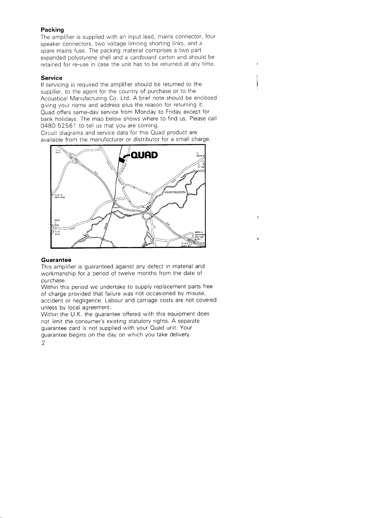
lf servicing
supplier,
Acoustical
giving your
Ouad
bank
0480
Clrcuit
available
to the agent
offers
holidays.
52561
diagrams
from the
is required the amplifier
for the country
Ltd. A brief
Manufacturing
name and address
same-daV
The map below
to tell
and service
manufacturer or distributor
Co.
service
us that
plus
from Monday
shows
you
are
for this
data
should
purchase
of
reason for
the
where to
coming.
Ouad
returned to the
be
to the
or
note should be enclosed
returning it.
to Friday except
find us. Please
product
for a small charge.
for
call
are
Guarantee
This amplifier
workmanship
purchase.
Within this
of charge
accident or
unless by
Within the U.K.
not limit the consumer's
guarantee
guarantee
)
guaranteed
is
period
for a
period
we undertake
provided
negligence.
local agreement.
the
is not supplied
card
begins on the day on
failure was
that
Labour and carriage
guarantee
against any
twelve
of
to supply
offered
existing statutory
with
which
defect
months
not occastoned
with this
your
Ouad
you
in material and
from the date of
replacement
costs are
equipment
rights. A separate
unit.
take delivery.
parts
by misuse,
not
covered
does
Your
free
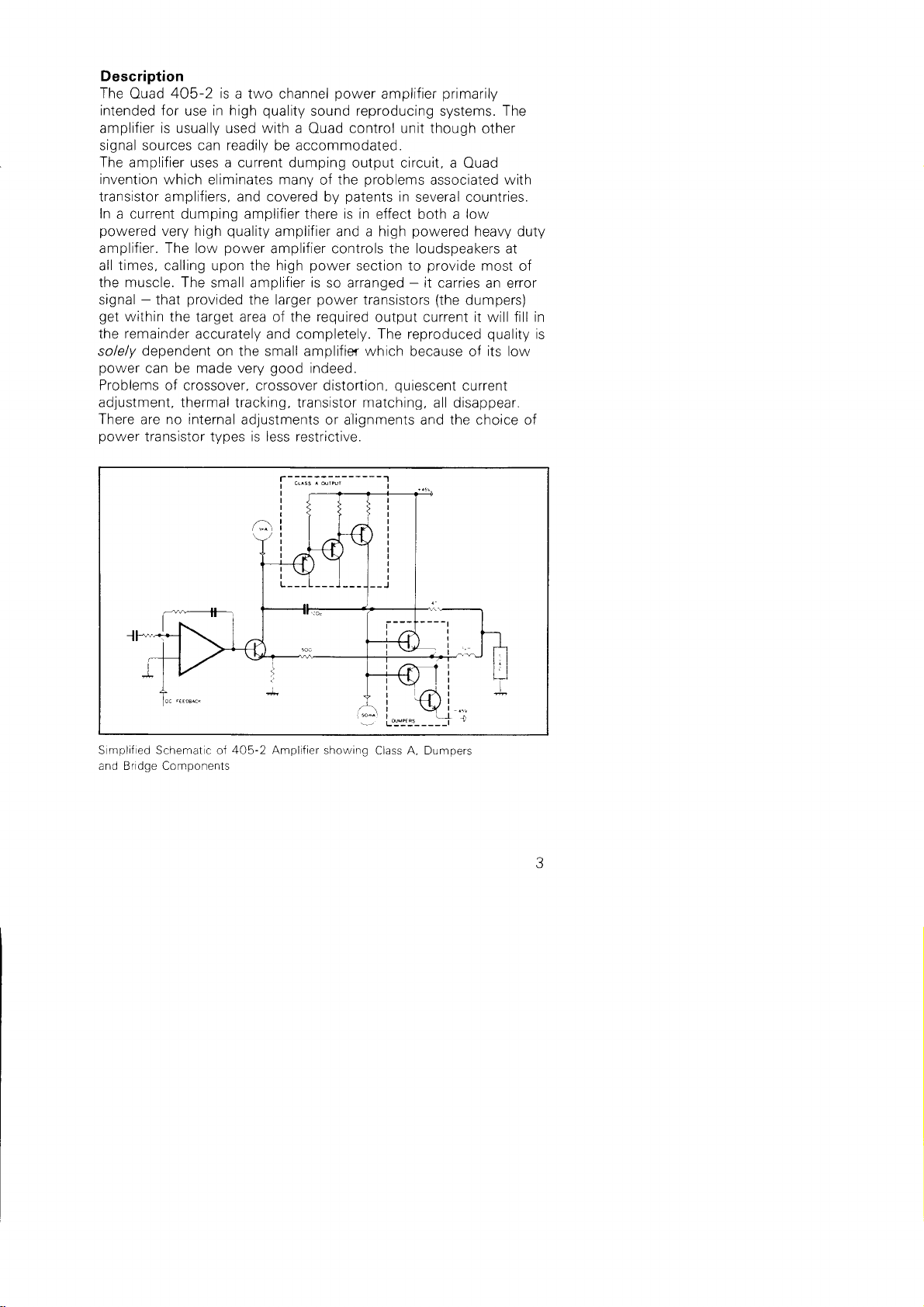
Description
The
intended for
Ouad
405-2 is
in high
use
a two channel
quality
amplifier is usually used with a
power
amplifier
sound reproducing systems. The
control unit though
Ouad
signal sources can readily be accommodaled
The amplifier uses a current dumping
invention
which eliminates manv
transistor amplifiers. and covered by
In
a current dumping amplifier there is in
powered
very high
amplifier. The low
times,
all
calling upon the high
the muscle. The
signal - that
get
within
the target area of the
the remainder
dependent
solely
power
Problems
can be made very
of crossover. crossover distortion,
adjustment. thermal
There are no internal
power
transistor types is less restrictive.
quality
power
amplifier and a high
amplifier controls the
small amplifier is so arranged - it carries
provided
the larger
accurately and completely. The reproduced
on the small amplifier which
good
tracking, transistor matching, all disappear.
adjustments or a'lignments and the choice of
output circuit, a Ouad
the
of
oroblems associated with
patents
effect both a low
power
section to
power
transistors
required
output current
indeed.
primarily
other
in
several countries.
powered
heavy duty
loudspeakers
provide
most
an error
(the
dumpers)
it
will fill
quality
because of
quiescent
its
current
at
of
in
is
low
S mplif ed Schemat c of 405-2 Amplifier showing
and Bridge Components
Class A, Dumpers
405-2 is fitted with a
The
is a load-sensitive, time-dependent
This
problems
overcomes
The amplifier
B.5A
substantially
progressively
transistors
extreme
When the
current
the
will
deliver an
into any
load. lf
below
4fl
reduced to a
to remain within their safe
case of a short circuit
level falls or the short
signal
gradually
limit
This enables the amplifier
load when handling a normal music
any
nrntp.t;nn tho ^rtnlt
purelV
for
reactive
extended
an
circuit or
on signal
new
associated
instantaneous
load is too
the
the current
,
value which enables the output
this value
returns to its initial
to deliver
deViCeS
frOm
loads.
period (minutes)
INSTALLATION
The Ouad
sight
The Ouad
must
n:hinet nr cr rnhn:rd
lf
used
cartridge,
radiation from the
by
The current
enables
programme
normal temperatures
When operated
heatsinks
405-2 carries no controls
in a cabinet or
405-2 is
always
be adequately
in
close
care
any other
provided
proximity
should
be taken
to the control unit,
mains transformer of
dumping
robust transistors
extra
qualrty
crrcuit technique
and the amplifier
without compromising
power
high
at
hot
to be
the touch.
to
convenient
with a substantial
ventilated,
levels
Ouad-designed
current
with conventional
maximum current of
reactrve,
or of
limit is smoothly and
operating area.
is
3.1A.
circuit is
level.
peak
high
currents
programme.
SUStained
Shorting
OVerlOadS
both outputs simultaneously
is not
and may be
location.
particularly
tuner or
to ensure that
hum is
rhe 405-2.
in the Ouad
used
to be used
without
can operate
reliabiiity.
quite
it is
normal
protection
limiter which
circuit.
"load-line"
a resistance
In the
removed the
into
alnrost
fully
while
into ShOrt
protected.
mounted out of
heat sink, and
positioned
if
magnetic
not induced
405-2
impairing
higher than
at
for the
circuits
in
a
Input
AC
The Ouad
2OO-24OV
4O5-2 is suitable
.iOO-120V
or
Before connecting
voltage selector,
Voltages
affect
of up to
performance.
AC mains
the unit
which should
internationally
Blue neutral, see
located
10% above or
input is via a standard
agreed
Fig.
4
for use on either
AC supples.
the Ouad
405-2 to
the
on
rear
below the
three
be w red
code, Green/vellow
'1
.
in
accordance
the
panel
pin
5OHz or 60Hz,
supply
is
ensure
correctly
indicated
plug
Euro
with the
Brown
earth,
that the
set.
range do not
supplied
with
live and

Frg
(Bro^n)
L\e
v,G
'\1
Earth
(.
l
A
{Green/Ye
Inp-r
Co^necror C[122
ow)
Earthing
The
signal source via the 4-pin Din
its AC
of
Normally
44 control unit
any 34 or a 44 after
volume
disconnected from
the earth
relying
lf this
connection
(Grounding)
Ouad 405-2 should
be connected to
signal lead
mains lead,
a 3-core mains lead
but
not
both or it may
should be used with
and a 2-core lead with
number
serlal
control at minimum
the control unit,
and
25800. hum
with
then it is
connection at one end of the interconnecting
on the signal lead to
does not clear the hum
broken but
investiqate
earth
do
the
not
further
Fuses
In addition
amplifier, each channel is
the
on
The main fuse is
2OO-250 volt
the mains
to
printed
suppiy fuse on
protected
by two internal
circuit boards.
a 2.5 amp surge-resisting
supplies while a 5 amp
required when operating with 100-1
case
all
reach
the amplifier, by undoing the
cover about
Withdraw the mains
four
the
internal
internal
'1
O mm,
fuses
are 4 amp
fuses it is necessary
retaining
two
(0.5"),
plug
backwards
before removtng
The rndicator lamp on the amplifier is
supply. lf the
but illumination
;^r^.^^l {,,-^^ -.^ ;^+^^+
'trtqt
I
oL
indicator lamp is
of
ctY
il rLqut.
tu)Y)
on, the main fuse
the indicator larnp
earth either through the
or through the third wire
cause hum.
a Ouad 34 or
the
Ouad 33. but
occurs with the
all
other eouioment
permissible
amplifier via the
operate with
the earth
to ascertain the
the
of the
panel
rear
fuses,
(2.5AT)
surge-resisting
25 volt
quick
blowing
to remove
screws
before lifting
type
(5AT)
supplies. In
(4AF).
the
top cover
and sliding
it
the cover.
powered
from
the *50 voit
must
does not imply
that
if. with
to break
mains lead,
control unit.
cause.
located
ior
fuse
is
either
To
of
the
clear.
be intact,
the

Input Connections
inpui lead supplied
The
sources
signal
marked
output
For a Quad
with
For
but the
cnannet.
sockets
it.
remote
other than
R and should
L and
the
of
control
Pin 1 is
total capacitv
left, Pin
installation
with the Ouad
a Ouad control
be connected
pre-amplifier
unit, use
of the
the
2 screen.
longer
runs of screened
lead should
405-2 shou
mixer.
or
pir'|4 pin
4
Pin 3
d be used
phono
The
unit.
to the appropriate
Din lead supplied
right, Pin 4 blank.
may be used,
cable
not exceed
2OOOpF
with
plugs
per
are
Loudspeaker
The Ouad
black
and
unconditionally
For
cable.
impedance
loudspeaker
Each
output
wav, to ensure
terminals
Should
experimentally
used
the other
In
loudspeaker,
provided
the
The outputs
to
applications.
attempt
the
6
so that
for mono, etther
cases
loudspeaker
Each
amplifier,
produce
Loudspeaker
The loudspeaker
recommended
below'1OOW
amplifier
loudspeaker and
Maximum safe
dependent
manufacturers
Some
iers exceeding
amplif
orecautions
Connections
4O5-2
plugs
are
stable
optimum
of the
the two
that the
colour-coded
are
be any doubt
there
(See
channel
where
to connect
louospeakers.
also
with the
the
or
the
of
ngle channel
s
a
A separate
Protection
amplifier
(into
should
be
power
so
and
observed.
are
is fitted
cable
should
left vacant.
require an
loudspeaker
should
manutacturer
with standard
packed
performance
Page B).
protection
405-2 can
the
BQ)
fitted.
is difficult
wlth
may be used
and
is small
be connected
pairs
of
speakers
facilitate this.
to
the
Where one
channel
infringe
for
will
the
may be
A
such as
energising
be capable
power
sheet
data
red output
power
then the
Failure to
its
most
to define
permit
quoted
This can
should
usually
wires are connected
phasing
facility descrbed
be
for
loudspeakers
4mm sockets and
the unrt.
it is
relative
operate
dummy
connected
his
iimiter
guarantee.
their
handling capacity
The Ouad
with any
necessary to ensure
to the
to
can be
loudspeaker oniy
used and the term
load resisior
the electrostat
supplV
followed.
be
handling
of
ier
amplif
is
ava
terminals
states
loudspeaker.
faciiities
do so
precisely
loudspeakers
sometimes
type of speaker
impedance of
its
appropriate
phase.
n
checked
the
beiow
in serres or
for
special
lable on
together.
maximum
a
provided
may cause damage
is
time
for a music signal
be advantageous
two
405-2
that
amplifier
rn
the
The output
later
nals of
is not
c
instrrctions
full
the
output
should
n
request Do
figure
lf
this
with
frequency
and
used
to be
provided
red
is
the
the load.
same
is
required,
of
be used.
parallel
not
is
the
to
witn
certain
in
{
I
I

enabling short
overload.
should
always be obtained before embarking on
Each channel of the amplifier
which cuts off signal to the
component
lou
dspea
duration high level
The
advice of the
loudspeaker manufacturer or
incorporates a DC sensing
loudspeakers in the
failure which would otherwise be
kers.
peaks
to be handled
such a
event of
likely
to damage the
without
his
agenl
procedure
circuit
Output
To limit the
two shorting
provided
llustrated
oaded
pushed
withdraw the mains
Limiter
output
links
in
each
below.
(see
d,agram) and
firmly
home but
to 20 volts rms insert the
supplied,
of the amplifier boards, as
These
sockets are spring
the
not
plug
and then
top cover by undorng rts two
1O
it
clear.
De
stirck
the
mm
sriding the cover about
backwaros and
t^L^l ^-^. !^! ^t-^,.r! I
provroed
laD€l
amplifier
lilting
srrouid
to indicate that
f irted.
in
the sockets
links
should be
soldered.
retarnrng
First
remove
screws,
the
(0.5")
The
adhesrve
on to the
limiters have been
Electrostatic
Ouad
The Ouad
place
in
each
405-2 amplifier should
when driving a
channel.
When two such speakers
(stacked pairs)
limiters
Loudspeakers
slight
thev
in
circuit.
prior
modification before being used
have
alreadv
Loudspeaker
singre Ouad
they should be connected
to serial number
been modified for use with the
(Old
Model)
always
have the voltage
electrostatic
loudspeaker
are used on eacl-r channel
parallel
in
16800
with
the
(March
w,ith
1966) need
405-2 unless
Ouad
Ouad 303.
limiters
on
the

I
I
Loudspeaker
lf there
connected
playing a mono
uoo"ai
lndefinrte
both,
will
full-bodied
Headphones
HeadIhones
place
shown
will
orovide
to suit
require
Electrostatic
connected
The
n"..rruryi
or
is any
to emanate
should
give
of
in Fig.
provide
most
loudspeaker
earth.
lErr cxltrtruel
Phasing
doubt
(see
connections
the
be
definite
a
sound
should
loudspeakers
the
(i).
the
rncorporating
for
magnetic
dummy
or other
in accordance
must
about
their
6),
Page
both
over
disc
from a
to either
reversed.
sound
centre
tenor
the
ln
be connected
the
of
Any
necessary
the
headphones.
res stors.
load
types
wlth
leads
return
taken
be
I
in
way
the
phasing
channels.
point
midway
of
Correctly
and
swtching
requirlng a
to
connected
source
bass
and
to
cal
a typ
headphone
and
resistors
The
manufacturers'
(which may
black
the
the
which
now be
may
the
when
belween
loudspeakers,
the
the
accompanied
registers'
405-2
Ouad
the
arrangement
wiring
switch
which
Ouad
high
sockets
untts
of
many
adiust
405-2
level
lnstructions'
commoned
be
and
loudspeaKers
checked
sound
them
loudspeakers
by
outputs
on
them
the signal
cioes
should
input
never
are
by
should
ls
lf this
not
but
more
a
in
is
market
the
also
level
not
be
lf
to chassis
I
t
1
I
i
i
I
Fig.
t
d

Additional
(ii)
Fig.
ioudspeakers
Loudspeakers
shows the switching arrangements if
is to be used. The
type or one of the
ila
ava
ble.
proprietary
switch boxes which
switch
may
more than
be either
are
of the
readily
one
pair
rotary
o{
LOUDSPEAKER
Fig.
ii
SWITCHING FOR
OUAD
405
SWITCH OPERATION
405
OUAD
LT RT
.I

OUAD
405-2
SPECIFICATION
Measurements
channel
Power
The
nominal
Power
Continuous
10.000
For
operating.
Output
amplifier
impedance.
and
lOO
Nz
lOOO Hz
Hz
other
impedances
distortion for
sine wave
any level up
any level
any level
apply
to elther
is intended
various
into
ro 100
up
to 1OO
up ro
and
voLts
dBV
channel,
for
use with loudspeakers
with
or without
frequencies.
BQ resistive
wats
watrs
100 watts
freqrtencies
load.
<
0.01% D
<
0.01%
<
O.O5% D
graphs.
see
of 41
tot
D tot
tot
the
other
6A
10
LOAD RES]SIANCE
MAXIMUM
OUTPUT VOLTS AS
FR€OUENCY
FREQUENCY
FOF
VASIOUS
OHMS
A FUNCTION
LOAOS E
OF
DISTOFT]ON
i
I

Notes:
1 . The
curves
output
depends
into
upon
show
resistive
the immediate past
loudspeaker
loads
approximates
2. With
the
additional
voltage
performance
is limited
figures
maximum
loads.
short term
Performance
the impedance
history
of the
and music
peak
power
+
power
limiter
1O%
to the
to 20V
unchanged.
and long
into
phase
and
signal.
angle
In
programme,
curve.
inserted
(50
the
watrs
term
reactive
of
practice
power
output
maximum
BO),
ail other
power
loads
the load
with
output
and
Output Internal
3.3pH in
Offset
Frequency
Ref. 1
Low frequency
High
series
(
7mV.
kHz
frequency
0
dB
-10
Response
-1
-O.5dB
lmpedance
with
0.03O
dB
at 20 l1z.
20
and
Offset
Filter
attenuation
-3dB
k1z
f
Low FREOUENCy
zts
, | | lll | |
1OH2
bO kHz.
I
ttttil|
tNpUT
100H2
as
|
FTLTER
curve.
tllllll
RESPONSE
1 KHz
Signal Input
O.5V rms
input
+
by 2OkO
Level
0.5d8
parallel
in
for
1OO
with 22OpF.
watrs into
Be.
Amplifier
loads
the
11

Signal
0.1
Provided
figure and the
all
transient or
or outside
power.
then
on
Input Slew
V4r S.
the rate of change
amplifier
distortions appearlng
repetitive
the audio
lf
malor
the
-BOdB
(0.01%)
programme.
Rate Limit
input voltages does
of
is not driven
in the audio
waveforms with
will be at
range
portion
of
the
represents the
not exceed this
into clipping. then
(20-20.000
range
frequency components
least
input
energy
maximum
BOdB
is
possible
below
wanted signal
the total of
Hz) due to
inside
full rated
distortion
Signal
Instantaneous
Input Overload
recovery up to
Crosstalk
(lnput
loaded by 1 kA) BOdB @
Noise
and
Hum
'A'
weighted
Unweighted
-96d8
-93d8
Protection
The Ouad
conditlons
405-2
and is electrically
8.5 amperes
steady
state
simultaneously
eventual
breakdown.
is
peak
current
into a short circuit.
for an extended
Stability
Unconditionally
stable
Power Input
1 10-1
50-60
20-1 30V,
Hz, 3O-350
220-230-240V
*2OdB overload.
1
OO
70dB
60dB @
ref full
power (1
ref full
suitable
1 kHz
@
'10
power
5.7
for use under
protected
into
load reducing to 3.'1 amperes
any
Shorting both outpLrts
period
with any
load and any signal.
watts depending
Hz
kHz.
kHz measurement
the most arduous
by current
limiters;
bandwidth).
music
will result in overheating and
on signai
level.
1
Dimensions
Height
115mm
Width 340.5
Depth
195 mm
allow an extra
Weight
(20
Kg
9
lbs
)
mm
38
(45")
(13.4")
\1
mm
prnred
7"1
(1
.5") for
n
Ensand
plug
and socket.
bv cranpress
Knss Ly'nn

The Acoustical
H U NTi
Cambs.,
PE-18 7DB,
NGDON,
Manufacturing
Co.
Ltd.,
Telephone
Telex:
Ouad
No.: Huntingdon
is a regrstered trade
(0480)
32348 OUAD
ntark
52561
G
I
 Loading...