

Page 1

Q-TECH
COR PORATI ON
Description
Q-Tech’s voltage-controlled crystal oscillators (VCXO)
consist of a varactor diode and associated circuitry such as a
bipolar transistor or logic IC amplifier, logic output buffers
and/or logic divider stages, and a round AT high-precision
quartz crystal built in a wide selection of Dual-In-Line (DIP)
or Surface -Mount (SMT) hermetically sealed packages.
Features
• Made in the USA
• ECCN: EAR99
• DFARS 252-225-7014 Compliant:
Electronic Component Exemption
• USML Registration # M17677
• Wide frequency range from 1kHz to 155.52MHz
• Wide operating temperature range -55ºC to +125ºC
• Choice of output logic options ( ACMOS, HCMOS,
LVHCMOS, TTL, Sine, and ECL outputs)
• Supply voltage -5.2Vdc & 5Vdc ±10%
• Hermetically sealed package
• Tight or custom symmetry available
• Wide pull range up to ±500ppm (optional)
• Special linearity (<5%, <10% optional)
• Positive or Negative Transfer function
• Bipolar control (±Vc)
• Fundamental designs
• Q-Tech does not use pure lead or pure tin in its
products
• RoHS compliant
VOLTAGE CONTROLLED (VCXO)
CRYSTAL CLOCK OSCILLATORS
-5.2Vdc & 5.0Vdc - 1kHz to 155.52MHz
Applications
• Frequency synthesis
• Clock recovery
• Phase-lock loop (PLL) applications
• Telecommunication
• Applications requiring frequency modulation or
electronic control of the oscillator frequency
Q-TEC H C orp ora tio n - 101 50 W. Jefferson Bou lev ard , C ulv er City 90232 - Tel : 310 -83 6-7 900 - F ax: 3 10- 836 -21 57 - ww w.q-te ch .co m
Voltage Controlled (VCXO) (Revision E, August 2010 ) (ECO# 9940)
Q-Tech offers custom design VCXOs in SMT packages
(QT78, QT88) at 3.3 Vdc and 5.0Vdc up to 72MHz. Please
contact Q-Tech for details.
1
Page 2
VOLTAGE CONTROLLED (VCXO)
Q-TECH
COR PORATI ON
-5.2Vdc & 5.0Vdc - 1kHz to 155.52MHz
CRYSTAL CLOCK OSCILLATORS
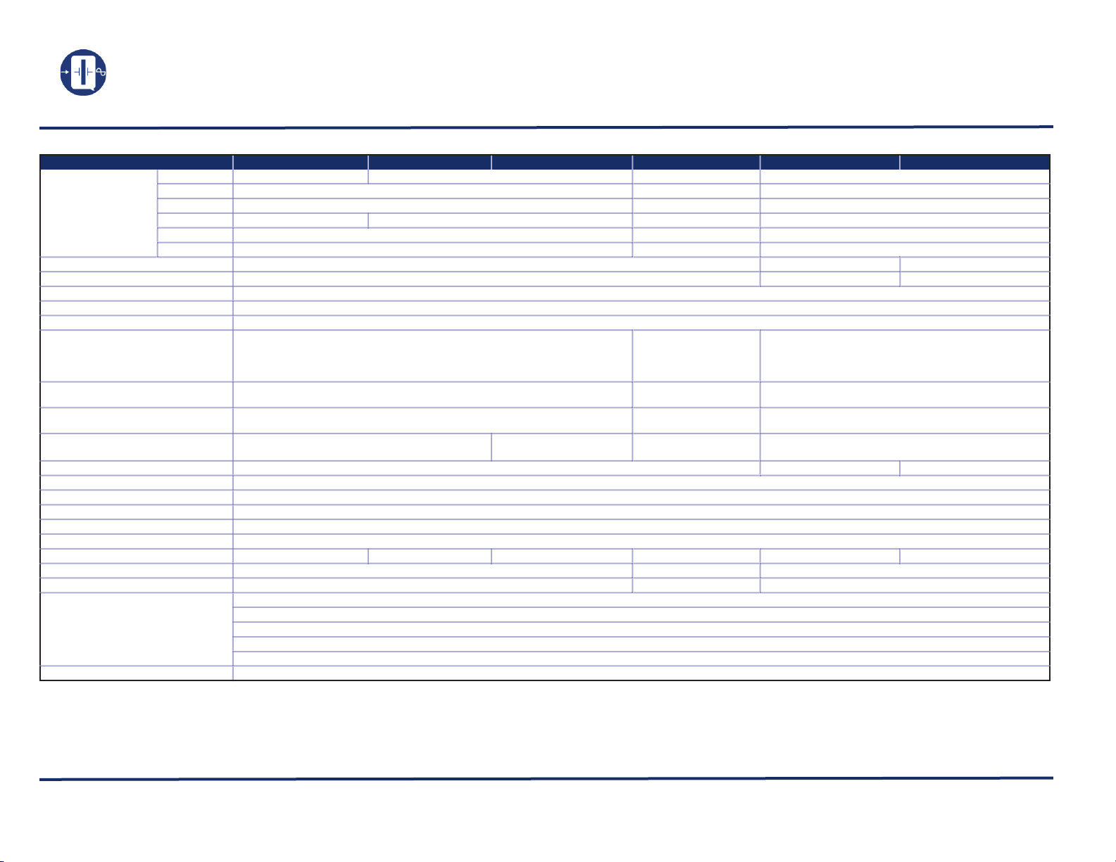
Electrical Characteristics
Parameters ACMOS HCMOS TTL
QT6, 18, 41, 42
QT50
Output freq. range (Fo)
(See note 1)
Supply voltage (Vcc) (See note 2) 5.0Vdc ± 10% -5.2Vdc ± 5% 5.0Vdc ± 5% (PECL)
Maximum Applied Voltage (Vdd max.)
Freq. stability (∆F/∆T) See Option codes
Operating temp. (Topr) See Option codes
Storage temp. (Tsto) -62ºC to + 125ºC
Operating supply current
(No Load)
Symmetry
(See note 3)
Rise and Fall times (Tr/Tf)
(with typical load)
Output Load
Control Voltage Vc (See note 4) 0V to 5Vdc
Frequency pulling (See note 5)
Transfer function (See note 6)
Linearity (See note 7) ± 10% max.
Modulation bandwidth
Input impedance
Output logic ACMOS
Harmonics (See note 8)
Subharmonics (See note 8) N/A
Phase noise (typ.)
(See note 9)
Start-up time 10ms max.
QT57
QT24
QT62
QT75
375kHz — 70MHz
375kHz — 27MHz
1kHz — 155.52MHz
375kHz — 70MHz 1kHz — 70MHz
1MHz — 27MHz
15MHz — 70MHz
25 mA max. Fo < 20MHz
35 mA max. Fo ~ 20MHz to < 30MHz
45 mA max. Fo ~ 30MHz to < 70MHz
65 mA max. Fo ~ 70MHz to 155.52MHz
45/55% max. Fo < 12MHz
40/60% max. Fo~ 12MHz to 155.52MHz
6ns max. Fo < 30MHz
3ns max. Fo ~ 30MHz to 155.52MHz
15pF // 10kΩ 10TTL Fo < 20MHz
HCMOS TTL
Notes: Custom designs are available with Q-Tech custom MCM part numbers.
1. Other frequencies and packages are available. Please contact for details.
2. Other supply voltages are available. Please contact for details.
3. Tighter symmetry is available other than 40/60% max.
4. Other Vc and bipolar control voltages are available. Please contact for details.
5. Wide frequency pulling is available up to ±500ppm min. APR is also available.
Q-T ECH Corporation - 10 150 W. Jefferson Boulevard, Culver City 902 32 - Tel: 310-836-7900 - Fax: 310-836-2157 - www.q-tech .c om
1kHz — 70MHz
-0.5 to +7.0Vdc
6TTL Fo ≥ 20 MHz
± 100ppm min.
Positive
up to 10kHz
> 10kΩ
10Hz -70dBc / Hz
100Hz -95dBc / Hz
1kHz -120dBc / Hz
10kHz -135dBc / Hz
100kHz -145dBc / Hz
SINE ECL
1MHz — 27MHz 12MHz — 27MHz
N/A
1MHz — 155.52MHz 12MHz — 155.52MHz
N/A
N/A N/A
N/A
0 to -8.0Vdc
65mA max. 65 mA max. Fo < 50MHz
N/A
N/A
50Ω 50Ω into Vcc -2V
Sine, 0dBm min.
-20dBc max.
-30dBc max.
85 mA max. Fo ~ 50MHz to 155.52MHz
3.5ns max. Fo < 125MHz
3.0ns max. Fo ~ 125MHz to 155.52MHz
0V to -5.2Vdc
10K / 10KHECL
N/A
Please call
N/A
40 / 60% max.
N/A
PECL
-0.5 to +7.0Vdc
0V to 5Vdc
PECL
6. Negative transfer function is available.
7. Better linearity than ±10% is available.
8. Harmonics better than -20dBc and subharmonics better than -30dBc are available.
9. Phase noise screening test is available.
Voltage Controlled (VCXO) (Revision E, August 2010 ) (ECO# 9940)
2
Page 3

Q-TECH
1 7
814
Q-TECH
P/N
FREQ.
D/C S/N
(22.35)
(15.24)
.880
.600
.300
(7.62)
(2.54)
.100
.505
(12.83)
MAX.
(.457)
.018
MIN.
(5.08)
.200
.200
(5.08)
MAX.
MAX.
14 8
71
FREQ.
D/C S/N
MCM
Q-TECH
.600
(15.24)
(7.62)
.300
.200
(5.08)
MAX.
MIN.
(5.08)
.200
(.457)
.018
MAX.
(20.32)
.800
.505
(12.83)
MAX.
Q-TECH
MCM
.600
.800
.200
.505
.300
.200
.018
FREQ.
D/C S/N
(12.83)
(7.62)
MAX.
(5.08)
MAX.
(5.08)
MIN.
(.457)
(20.32)
MAX.
(15.24)
14
58
ø .080
(ø 2.03)
.020
(.508)
14
58
Q-TECH
MCM
FREQ.
D/C S/N
.200
(5.08)
.250
(6.35)
(.508)
.020
(7.62)
.300
.505
(12.83)
(.457)
.018
MAX.
MIN.
SQ. MAX.
SQ.
ø .060
(ø 1.52)
(5.08)
.200
.250
(6.35)
.018
(0.457)
.100
(2.54)
.700
(17.78)
.980
(24.89)
.600
(15.24)
(20.45)
.805
FREQ.
P/N
Q-TECH
D/C S/N
81
16 9
MAX.
MIN.
MAX.
MAX.
1
10 11
20
Q-TECH
P/N
FREQ.
.120
(3.05)
(1.52/1.14)
.060/.045 .010
(.254)
(15.88)
.625
(
(
.050
(1.27)
(.381)
.015
MAX.
SQ.
D/C S/N
12
Q-TECH
P/N
FREQ.
D/C S/N
34
40
4416
(2.16)
.085
(.635)
.025
.500
(12.70
.050
(1.27)
(16.51)
.650
34
6144
40
(1.27)
.050
SQ.
SQ.
12
MAX.
+010
-.005
.350
1
- .005
.550
+ 010
.200
.050
1
2
3
2
4 3
+.25
-.127
(8.89 )
+.25
-.127
(13.97 )
(5.08)
(1.27)
.115 MAX
(2.92)
4
Q-TECH
P/N
FREQ.
D/C S/N
SQ. (4x)
COR PORATI ON
Package Configuration Versus Pin Connections
Package Configuration Versus Pin Connections
VOLTAGE CONTROLLED (VCXO)
CRYSTAL CLOCK OSCILLATORS
-5.2Vdc & 5.0Vdc - 1kHz to 155.52MHz
QT6V
Vcc 14
GND 7
Out 8
Vc 1
QT57V
QT41V
Vcc 14
GND 7
Out 8
Vc 1
QT24V
QT42V
Vcc 14
GND 7
Out 8
Vc 1
QT62V
QT50V
Vcc 8
GND 4
Out 5
Vc 1
QT75V
GND 8
Q-TEC H C orp ora tio n - 101 50 W. Jefferson Bou lev ard , C ulv er City 90232 - Tel : 310 -83 6-7 900 - F ax: 3 10- 836 -21 57 - ww w.q-te ch .co m
Voltage Controlled (VCXO) (Revision E, August 2010 ) (ECO# 9940)
Vcc 16
Out 9
Vc 1
Vcc 13
GND 10
Out 11
Vc 12
Dimensions are in inches (mm)
Vcc 6, 12
GND 34, 40
Out 42
Vc 41
Vcc 4
GND 2
Out 3
Vc 1
3
Page 4

Q-TECH
COR PORATI ON
Ordering Information
VOLTAGE CONTROLLED (VCXO)
CRYSTAL CLOCK OSCILLATORS
-5.2Vdc & 5.0Vdc - 1kHz to 155.52MHz
Sample part number
QT50VAC9M-20. 0 0 0 M H z
QT 50 V AC 9M-20.000MHz
T = Standard
S = Solder Dip (*)
Model #
(See page 3)
Screened to
MIL-PRF-55310,level B
(Left blank if no screening
Output frequency
)
AC = ACMOS +5V
HC = HCMOS +5V
T = TTL +5V
S = Sine +5V
E = 10KECL -5.2V
EH = 10KHECL -5.2V
PE = PECL +5V
1 = ± 100ppm at 0ºC to +70ºC
4 = ± 50ppm at 0ºC to +70ºC
5 = ± 25ppm at -20ºC to +70ºC
6 = ± 50ppm at -55ºC to +105ºC
9 = ± 50ppm at -55ºC to +125ºC
10 = ± 100ppm at -55ºC to +125ºC
11 = ± 50ppm at -40ºC to +85ºC
12 = ± 100ppm at -40ºC to +85ºC
Packaging Options Other Options Available For An Additional Charge
• Standard packaging in black foam (DIP)
• Standard packaging in a locked anti-static cardboard (QT24)
• Standard packaging anti-static plastic tube (QT75)
• Optional Tape and Reel
• Lead forming available on all packages. Please contact for
details.
• (*) Hot Solder Dip Sn60 per MIL-PRF 55310
• P. I. N. D. test (MIL-STD 883, Method 2020)
• Lead trimming
• J-leads attached (QT75)
Specifications subject to change without prior notice.
Key parameters of a VCXO:
• Nominal Frequency (Fo): Output frequency at center control voltage Vc.
• Control Voltage: The available voltage range at the input of the VCXO to vary the frequency (i.e., 0 - 5V, ±4V, etc.).
• Deviation (pull range): The change in the output frequency as a function of control voltage.
• Transfer Function (sense): Direction of change in frequency as a function of control voltage.
• Temperature Range: Operating temperature range.
• Stability vs. Temperature: Percentage, or ppm, change of output frequency with respect to the temperature range at a constant
control voltage.
• Input Impedance: A measure of isolation between the VCXO internal frequency control network and the control voltage source.
• Linearity: The deviation from the best straight line slope of the frequency vs. control voltage plot.
• Modulation Bandwidth (rate): The maximum allowable rate of change of the control voltage.
Q-TEC H C orp ora tio n - 101 50 W. Jefferson Bou lev ard , C ulv er City 90232 - Tel : 310 -83 6-7 900 - F ax: 3 10- 836 -21 57 - ww w.q-te ch .co m
Voltage Controlled (VCXO) (Revision E, August 2010 ) (ECO# 9940)
4
Page 5

Q-TECH
39,992,000
39,994,000
39,996,000
39,998,000
40,000,000
40,002,000
40,004,000
40,006,000
40,008,000
0 0.5 1 1.5 2 2.5 3 3.5 4 4.5
Vc (V)
Output Frequency, Hz
-5%
-4%
-3%
-2%
-1%
0%
1%
2%
3%
4%
5%
Integral Linearity, %
5
SN1 SN2 SN3 SN4 SN1 integral linearity SN2 integral linearity SN3 integral linearity SN4 integral linearity
-600
-500
-400
-300
-200
-100
100
200
300
400
500
600
0 0.25 0.5 0.75 1 1.25 1.5 1.75 2 2.25 2.5 2.75 3 3.25 3.5 3.75 4 4.25 4.5 4.75 5 5.25 5.5 5.75
Applied Vc, volts
Frequency Deviation, PPM
0
3721 3737 3739 3722 3723 3724 3725 3727 3728 3731 3732 3734 3735 3736 3738
0
-50
-40
-30
-20
-10
10
20
30
40
50
-45 -40 -35 -30 -25 -20 -15 -10 -5 0510 15 20 25 30 35 40 45 50 55 60 65 70 75 80 85 90
Temp (°C)
Frequency Deviation, PPM
-8%
-6%
-4%
-2%
0%
2%
4%
6%
8%
0 0.25 0.5 0.75 1 1.25 1.5 1.75 2 2.25 2.5 2.75 3 3.25 3.5 3.75 4 4.25 4.5 4.75 5
VC (V)
Integral Linearity, %
-300
-200
-100
100
200
300
400
Frequency Pulling, PPM
0
Vdd
GND
0.1xVdd
0.9xVdd
VOH
VOL
Tr Tf
TH
T
0.5xVdd
SYMMETRY = x 100%
TH
T
0
-5%
-4%
-3%
-2%
-1%
0%
1%
2%
3%
4%
5%
0 0.25 0.5 0.75 1 1.25 1.5 1.75 2 2.25 2.5 2.75 3 3.25 3.5 3.75 4 4.25 4.5 4.75 5
Vc (V)
Integral Linearity, %
-300
-250
-200
-150
-100
-50
50
100
150
200
250
300
Frequency Pulling, ppm
100.2°C Integral Linearity 25°C Integral Linearity -54.9°C Integral Linearity 2 100.2°C centered 2 25°C centered 2 -54.9°C centered
-
-
Output
Ground
Vcc
DUT
Out
GND
0.1µF
15pF
Vc
Vc
Power
Supply
10k
mA
Vdc
+
+
+
(*)
or
0.01µF
(*) CL includes probe and jig capacitance
Typical test circuit for VCXO CMOS logic
COR PORATI ON
Frequency vs. Temperature Curve
QT6VHC-40MHz INTEGRAL LINEARITY AND PULLABILITY Vc=0V to 5Vdc QT58VHC-32MHz PULLING AND INTEGRAL LINEARITY
VOLTAGE CONTROLLED (VCXO)
CRYSTAL CLOCK OSCILLATORS
-5.2Vdc & 5.0Vdc - 1kHz to 155.52MHz
WIDE PULL VCXO QT957S - 16MHZ
Output Waveform (Typical)
WIDE PULL VCXO QT957S-16MHz FREQUENCY STABILITY VS. TEMPERATURE
QT75VHC-54.04MHz FREQUENCY PULLING AND LINEARITY VC=0V TO 5Vdc
Test Circuit
Q-TEC H C orp ora tio n - 101 50 W. Jefferson Bou lev ard , C ulv er City 90232 - Tel : 310 -83 6-7 900 - F ax: 3 10- 836 -21 57 - ww w.q-te ch .co m
Voltage Controlled (VCXO) (Revision E, August 2010 ) (ECO# 9940)
5
Page 6

Q-TECH
COR PORATI ON
Phase Noise and Phase Jitter Integration
VOLTAGE CONTROLLED (VCXO)
CRYSTAL CLOCK OSCILLATORS
-5.2Vdc & 5.0Vdc - 1kHz to 155.52MHz
QT25VT, 29.5MHz
QT50VAC, 31.9488MHz
Period Jitter
QT6VHC10M, 16MHz
QT25VT, 29.5MHz
Environmental Specifications
Q-Tech Standard Screening/QCI (MIL-PRF55310) is available for all of our VCXO packages. Q-Tech can also customize screening
and test procedures to meet your specific requirements. The units are designed and processed to exceed the following test conditions:
Environmental Test Test Conditions
Temperature cycling MIL-STD-883, Method 1010, Cond. B
Constant acceleration MIL-STD-883, Method 2001, Cond. A, Y1
Seal: Fine and Gross Leak MIL-STD-883, Method 1014, Cond. A and C
Burn-in 160 hours, 125°C with load
Aging 30 days, 70°C, ± 1.5ppm max
Vibration sinusoidal MIL-STD-202, Method 204, Cond. D
Shock, non operating MIL-STD-202, Method 213, Cond. I
Thermal shock, non operating MIL-STD-202, Method 107, Cond. B
Ambient pressure, non operating MIL-STD-202, 105, Cond. C, 5 minutes dwell time minimum
Resistance to solder heat MIL-STD-202, Method 210, Cond. B or C
Moisture resistance MIL-STD-202, Method 106
Terminal strength MIL-STD-202, Method 211, Cond. C
Resistance to solvents MIL-STD-202, Method 215
Solderability MIL-STD-202, Method 208
ESD Classification MIL-STD-883, Method 3015, Class 1 HBM 0 to 1,999V
Moisture Sensitivity Level J-STD-020, MSL=1
Please contact Q-Tech for higher shock requirements
Q-TEC H C orp ora tio n - 101 50 W. Jefferson Bou lev ard , C ulv er City 902 32 - Tel: 310-836-7900 - Fax: 310-836-2157 - www.q-t e ch. co m
Voltage Controlled (VCXO) (Revision E, August 2010 ) (ECO# 9940)
6
 Loading...