

Page 1

QTech SMS Controller
Quick Start Guide
Page 2
QTech SMS Controller - Quick Start Guide – v1.4 – February 2014 2
Introduction
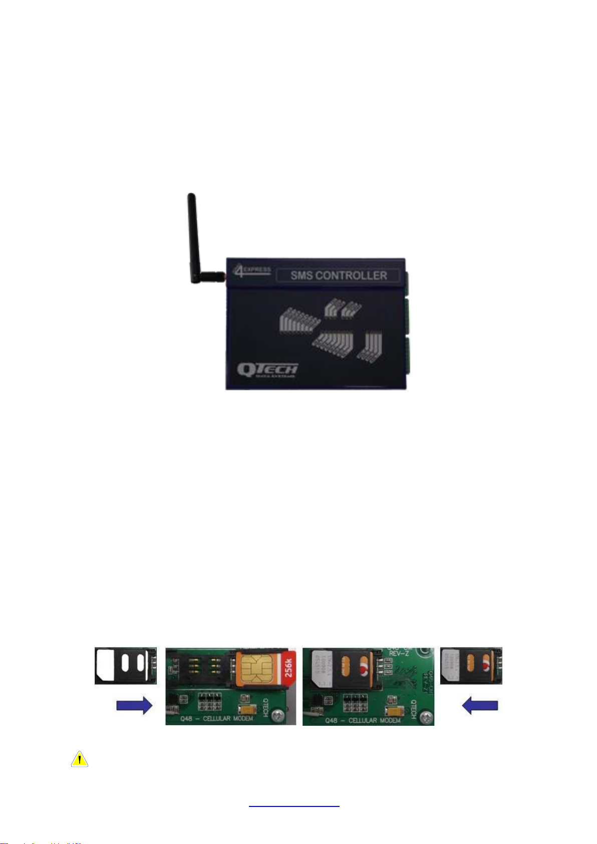
The SMS Controller is a powerful cellular remote control unit. It uses text messages
to provide multiple people with status conditions, alarms and control options.
Setup and configuration of the SMS Controller is via “Workbench”, a user friendly PC
application for Microsoft Windows 7/XP. Setup can be performed “offline” allowing
you to pre-configure SMS Controllers. These configurations can then be saved for
future use.
There are two versions of the SMS Controller, P/N PD8610 GSM/GPRS for
Vodafone/2Degrees or P/N PD8611 Quad band for Telecom XT/Vodafone/2Degress.
Each SMS Controller is supplied with the following:
Qty 1x SMS Controller Module
Qty 1x Aerial (stub type), 2dBi gain (P/N PD9230)
Qty 1x USB (Type A-B) Programming Cable (P/N CB-USB-AB)
Qty 1x CD-ROM containing Workbench configuration software
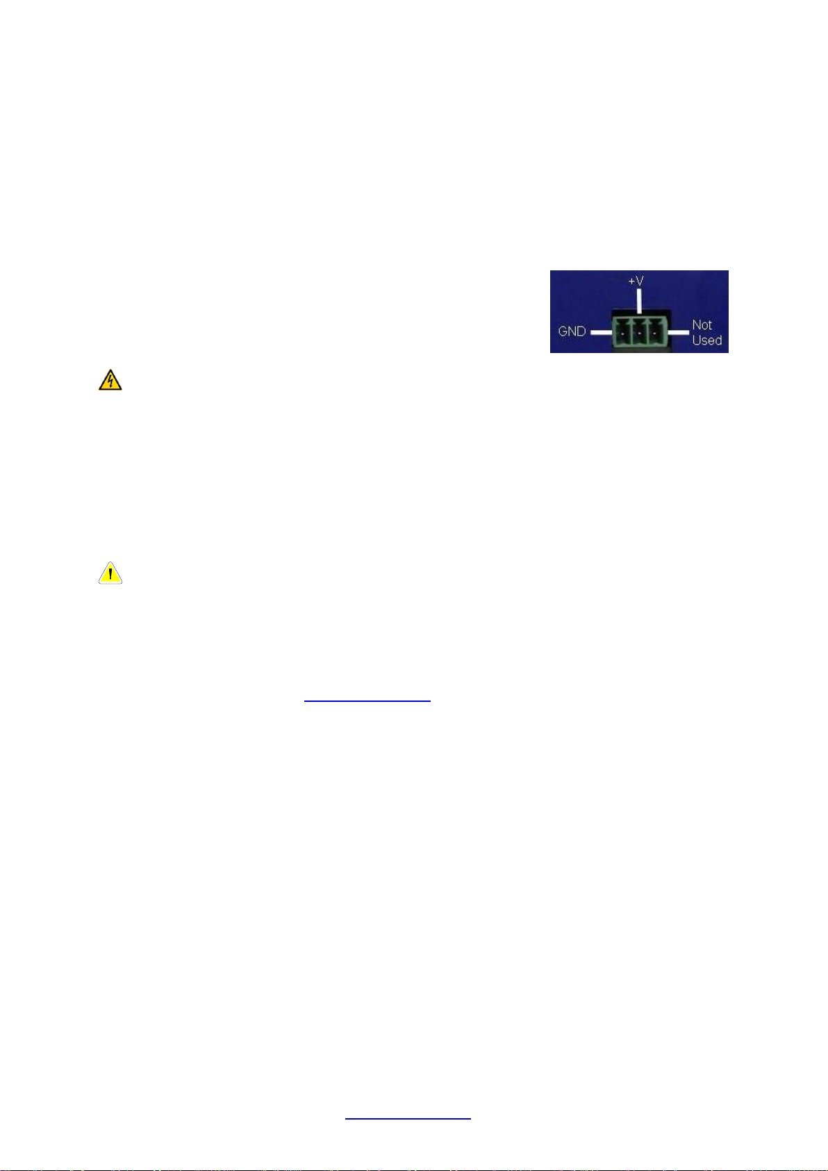
Install the SIM Card
Before installing the SIM card, ensure that it is activated. We recommend you insert
the SIM into a regular cell phone to prove this.
Carefully remove the SMS Controller cover by prising the side panels close to the
retaining dimples.
Locate the SIM card holder adjacent to the aerial. Push the top part of the holder in
the direction of the “Open” arrows (away from the aerial). Carefully insert the SIM
card from your chosen Telco. Be careful to orientate the card correctly. Finally,
carefully slide the plastic retainer towards the aerial.
Unlock Holder Insert SIM Close Holder Lock Holder
Note – The SIM card must be a “full size” card, not a “micro SIM”.
www.qtech.co.nz Tel: 03 3663713
Page 3
QTech SMS Controller - Quick Start Guide – v1.4 – February 2014 3
Connect the supply to the power connector, positive to the
“+V” terminal, negative to “GND”. The third terminal on
the right is not used.
We recommend the QTech plug pack P/N PD5412.
Aerial Connection
Carefully connect the aerial. Do not operate the SMS Controller without an aerial
connected. Refer to the aerial notes section on page 6 for alternatives.
Power Supply Connection
The SMS Controller is powered from an external 12-30 V DC supply.
Warning – Do NOT use Switch Mode Power Supplies (SMPS) with this
product. The DC power supply used for this product MUST have a grounded
negative or be a “linear” transformer based plug pack. The reason is that the
aerial, programming port and external connections can provide exposed earth
points and the SMPS can impose an AC voltage on the DC ground, which can
lead to damage. Suitable cost effective power supplies are available from
QTech: Plug Pack - P/N PD5412 or Power Pack with flying lead - PD5414.
Software Installation
Note – The software must be installed before connecting the SMS
Controller to your PC with the USB programming cable.
Insert the supplied SMS Controller CD into your PC.
If the setup program doesn’t run automatically, run the program in the root directory
of the CD called SMSWorkbench_vxyz_Setup.exe. Alternatively, download the
configuration software from www.qtech.co.nz
This will install the software in your Program Files folder, create a desktop shortcut
and install the required USB driver.
Power up the SMS Controller and connect it to the PC using the supplied USB cable
(type A to B). Within a minute you should see a message bubble displayed in the
system tray saying “Found New Hardware”. The installation is automatic and a few
seconds later you will see a further message bubble saying “Hardware is installed
and ready for use”.
Workbench User Interface
This is where the entire configuration of the SMS Controller takes place.
www.qtech.co.nz Tel: 03 3663713
Page 4
QTech SMS Controller - Quick Start Guide – v1.4 – February 2014 4
Follow the steps shown in the help
bubbles to get the basic aspects of the
SMS Controller set up.
The configuration is really intuitive, user
friendly and only takes a few moments.
Click “Enter” to accept an entry or click
in the help bubble to advance.
Enter a Device name for the SMS
Controller. We recommend using the
actual site name or customer name e.g.
“Pump Shed” or “Fred’s Farm” as this
name will appear in all the text
messages.
Each user will only receive the
messages they are interested in.
This is configured in the “Sequence”
section for each relevant I/O point.
In this example, Fred has control
options but Maintenance Staff don’t.
System Information – This contains details about the system.
The selections needed are the "Device Name", “County dialling prefix” (default is +64
for NZ) and “Service Provider”.
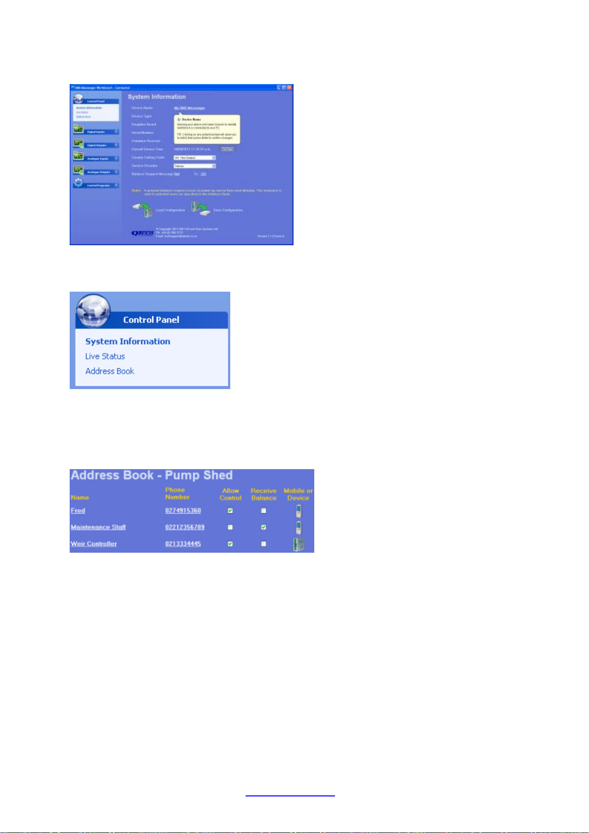
Address Book – Enter and edit user names and phone numbers for the texts.
Enter the name and phone number of all the people that you want to send texts to,
receive prepay balance messages or allow to control the system. Each person can
be individually given these abilities. Changes can easily be made in the future.
Press the test button to send a text to the person to show the system is working. This
test facility is also a great diagnostic tool to check the cellular network.
The SMS Controller can also text another SMS Controller! This powerful feature
allows a widespread use of the solution e.g. allows a weir upstream to be closed
when you have enough water. Use the “Device” option in the address book to
configure the other SMS Controllers.
Live Status – Summary page of the current status.
This shows all the inputs & outputs, their state and configuration information.
Click the I/O point to give it a name and set up what actions the SMS Controller is to
perform when the input changes.
www.qtech.co.nz Tel: 03 3663713
Page 5

QTech SMS Controller - Quick Start Guide – v1.4 – February 2014 5
We recommend using a
descriptive/the actual name e.g.
“Site Security”, as this name will
appear in all the text messages for
this point.
Please remember to save the configuration file
with a relevant/descriptive name e.g. “Smith Farm
Feb 2012”. This will be useful in the future and
will save you time making any changes or
enhancements.
If you are controlling outputs, try to keep the name short, as you need to type the
name in the text, e.g. “pump” would be a good suggestion as the control text would
be “turn on pump”.
The SMS Controller can automatically perform specified actions when something of
interest happens. The following screenshot shows that when the Site Security switch
opens, the security camera is switched on and after 30 seconds the alarm text is sent
to the owner.
Live Status is replaced with I/O Overview when you are offline and not connected to
an SMS Controller.
Note – Ensure the Notification “Do you want to receive SMS or Control for
this input” is set to “Yes” for all inputs you want to receive an SMS from or be
able to control that point. By default this is set to “No” to prevent unnecessary
SMS being sent when initially configuring the Controller
Physical I/O & Wiring Configurations
Digital Inputs
The digital inputs are normally open inputs that can be connected to suitable
mechanical switches, contacts and other closure devices. An input is active or ON
when the input switch is closed, and inactive or OFF when the input switch is open.
The digital input LED will light up when the input is ON.
Warning – Only mechanical switches or mechanical closure devices should
be connected to the inputs. No external voltage or other electrical source is to
be connected.
www.qtech.co.nz Tel: 03 3663713
Page 6

QTech SMS Controller - Quick Start Guide – v1.4 – February 2014 6
+ Supply
Dig Out 1
Tx
Anl In 1
G
Tx
G
Digital Outputs
The digital outputs are solid state devices designed to interface to a low power
relays. When an output is on, it will be connected to the power supply negative,
allowing current to flow into the output terminal to ground.
When in the OFF state, they have a high impedance to
ground and will float up to the power supply positive. The
digital output LED will light up when the output is ON.
To use a digital output with a relay, wire as shown in the
diagram opposite.
The maximum current available to drive all eight interface
relays is 1.5A. We suggest relays with a current of ~50mA.
Analogue Inputs
There are two analogue inputs configured for 4-20mA operation. (0-10V inputs are
available to order).
The Analogue Input LEDs show the status of the signal the RTU is receiving. If the
LED is off, it means the input signal is zero, or under-range. When the LED is on the
signal is within the measuring range that the input has been configured for. If the LED
is flashing, it shows the signal is over range.
4-20mA Devices
Any 4-20mA transducers must be powered using a separate
power supply from the analogue signal loop. If suitable, these
devices can be powered from the RTU power supply. If this is not
suitable, the analogue transducer can be powered from a
separate power supply as long as the grounds of both the RTU
and the other power supply are connected together.
Wiring of a 4-20mA device is as shown on the right.
0-10V Devices (Optional)
If your RTU is configured to use 0-10V transducers, these are
simply connected between the input and the Ground pin, as shown
on the right.
Analogue Outputs
There are two analogue outputs configured for 4-20mA operation. (0-10V outputs are
available to order).
The Analogue Output LEDs show the status of the outputs. If the LED is off the
output signal is zero. When the LED is on, it indicates the signal is greater than zero.
www.qtech.co.nz Tel: 03 3663713
Page 7

QTech SMS Controller - Quick Start Guide – v1.4 – February 2014 7
Our recommended optional aerial for external mounting,
is P/N PD9214, shown here.
This has ~4.2m of coax and is a panel mounting aerial.
To mount unscrew the plastic flange at the base of the
aerial to expose the mounting stud.
Drill a 6.5-7.5mm clearance hole in the panel, feed the
mounting stud through and carefully reinstall.
Other higher gain aerials are also available as options
for sites with inadequate signal strength.
Aerial Notes
The reliability of all cellular products is dependent on good signal strength. Before
deciding on the Telco to choose, please check coverage. We suggest that a cellular
phone is taken to site, to check the signal strength, ie how many “bars” are displayed.
The supplied stub aerial (P/N PD9230) should be suitable for locations with good
Telco coverage (full bars) and where the SMS Controller is in a non-conductive
enclosure (plastic etc).
Note – If the SMS Controller is to be enclosed in a metal cabinet, or the site
does not have full cellular signal, an optional external aerial will be required.
Note – Do not cut or join the coax cable, this will increase losses and
impact reliability.
Text Message Types
The following provide you useful information about the system:
Send “status” SMSC replies with all of the I/O values/states
Send “stats” SMSC replies with how many SMS’s have been sent; how many
SMS’s have failed the signal strength (RSSI) measurements and when the SMSC
was last reset by cycling the power supply
Send “stats reset” SMSC will reset the status information
Send the SMSC any text (even a blank one) and it will confirm the acceptable
message formats for the control abilities.
Notes for using the SMSC to SMSC text ability
The ability to send control texts between SMSC’s is very powerful. The following are
specific notes for these systems:
Only the digital outputs can be controlled (on/off/toggle/pulse), not analogues.
To receive status/stats info, you need to text the SMSCs individually:
remember to add all SMSC numbers to your phone’s contacts.
Digital Output Reply confirmations. This doesn’t work for SMSC to SMSC
control. Ensure “Reply with confirmation of control”: is set to No.
www.qtech.co.nz Tel: 03 3663713
Page 8

QTech SMS Controller - Quick Start Guide – v1.4 – February 2014 8
Symptom
Cause
Solution
Green PWR status LED
not blinking when power
applied
Blown fuse
Replace internal fuse. Use 2
Amp quick blow type.
Insufficient power
supply voltage
Check supply and provide
suitable power supply
No texts are received
Address book entry is
incorrect
Check settings and then send a
“test” text to the user
Telco credit expired
Top up as needed
SIM is not installed or
Reception/coverage is
poor
Check SIM card and send a
“test” text to the user from the
installed site
Unable to control an
output via text
Note, users who are in
the address book, will
receive a text to say they
do not have control
The user isn’t
configured as being
able to use control
Check address book settings
and select the “allow control”
option for the user.
The wrong command has
been sent to the
controller
Predetermined
formats are needed in
the text messages
Simply text the SMS Controller
(even a blank SMS) and it will
tell you the format of the allowed
messages. This is also shown in
Live Status of the Workbench
software
Consider saving frequently used
texts as a template in your cell
phone
Intermittent Operation
Telco signal strength
Send the SMS a “stats text.
Monitor it and/or upgrade aerial.
Status LEDs
PWR (Power) This LED is on when the device is powered on.
OK Flashes to show the device is active and not locked up.
ERR (Error) This LED flashes a number of times to indicate any errors.
COMS This LED shows the cellular communication status:
Off The cellular modem is off
Fast Blink (1s) Searching for network
Slow Blink (3s) Registered on network
On SMS in progress
RXD (Receive) This LED will flash when a SMS is received.
TXD (Transmit) This LED will flash when a SMS is sent.
Trouble Shooting and Tips
www.qtech.co.nz Tel: 03 3663713
 Loading...