

Page 1
GENERAL RELEASE DOCUMENT
CONSULT FACTORY FOR CURRENT REVISION
REVISIONS
REVISION
DESCRIPTION
APPROVED
DATE
1.0
Preliminary
Luis Vargas
8/13/2010
SPECIFICATION CONTROL DRAWING
Q-TECH CORPORATION
10150 W. JEFFERSON BLVD.
CULVER CITY, CA 90232-3510
PREPARED BY:
Luis Vargas
DATE
8/13/2010
LOW PROFILE 24 PIN FLAT-PACK HYBRID CRYSTAL
OSCILLATOR, VCXO, CLASS S,
Standard Design For Sine Wave up to 350MHz
UNLESS OTHERWISE
SPECIFIED, DIMENSIONS
ARE IN INCHES.
TOLERANCES:
3 PLACE DECIMAL = .005
2 PLACE DECIMAL = .02
1 PLACE DECIMAL = .1
FRACTIONS = ± 1/16
ANGLES = 2 DEGREES
CHECKED BY:
QUALITY
DATE
DRAWING NO.:
QTV714, QVT715 and QTV716
Sine-Wave 24 Flat Pack
REVISION
1.0
RELEASED BY:
DOCUMENT CONTROL
APPROVED BY:
ENGINEERING
DATE
SCALE
NONE
SIZE
A
CAGE CODE
51774
SHEET 1 of 7
Page 2
QTV714, QTV715 and QTV716
Sine-Wave 24 Flat Pack
REV.
Q-TECH Corporation
10150 W. Jefferson Blvd.
Culver City, CA 90232
SIZE
A
CAGE NO.
51774
Sheet 2 of 7
1.0
1.0 SCOPE
This specification establishes the detail requirements for low profile hybrid, hermetically sealed, Sine-
Wave output Voltage Controlled crystal oscillators (VCXO) for use in space flight missions.
2.0 APPLICABLE DOCUMENTS
The following documents of the latest issue form a part of this drawing to the extent specified herein.
2.1
Specifications and Standards
SPECIFICATIONS
MILITARY
MIL-S-19500
Semiconductor Devices, General Specification For
MIL-PRF-55310
Crystal Oscillators, General Specification For
MIL-PRF-38535
Integrated Circuits, (Microcircuits) Manufacturing, General Specification For
MIL-PRF-38534
Hybrid Microcircuits, General Specification For
STANDARDS
MILITARY
MIL-STD-202
Test Methods for Electronic and Electrical Component Parts
MIL-STD-883
Test Methods and Procedures for Microelectronics
MIL-STD-1686
Electrostatic Discharge Control Program for Protection of Electrical and
Electronics Parts, Assemblies and Equipment.
2.2 Conflicting Requirements
In the event of conflict between requirements of this specification and other requirements of the
applicable detail drawing, the precedence in which requirements shall govern, in descending order, is
as follows:
a) Applicable Customer purchase order.
b) Applicable detail drawing.
c) This specification.
d) Other specifications or standards referenced in 2.1 herein.
2.3 Customer Purchase Order Special Requirements
Additional special requirements shall be specified in the applicable Customer purchase order when
additional requirements or modifications specified herein are needed for compliance to special
program or product line requirements.
3.0 PERFORMANCE REQUIREMENTS
3.1 General Definition
The VCXO is a high reliability signal generator that provides a sine-wave output. The VCXO has been
designed to operate in a spaceflight environment with an expected lifetime in excess of 15 years.
Lifetime is defined as the sum of operational and storage environments.
Page 3
QTV714, QTV715 and QTV716
Sine-Wave 24 Flat Pack
REV.
Q-TECH Corporation
10150 W. Jefferson Blvd.
Culver City, CA 90232
SIZE
A
CAGE NO.
51774
Sheet 3 of 7
1.0
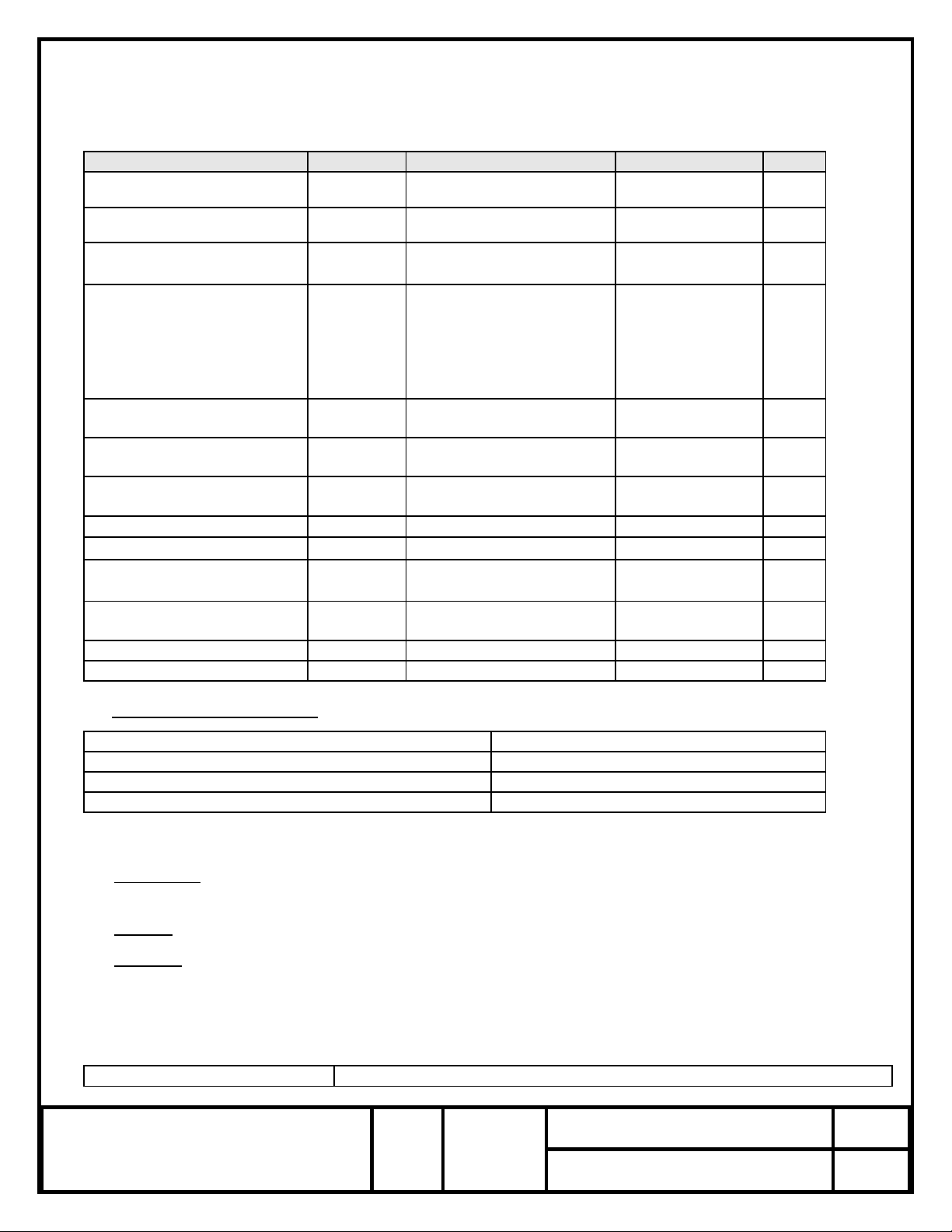
3.1.1 Electrical Characteristics
PARAMETER
SYMBOL
CONDITIONS
VALUE
UNIT
Frequency Nom.
fo
-
See part number
generation table
MHz
Supply voltage, Nom.
Vs
Vs±5%
See part number
generation table
V
Input Current, max.
Is
Vs, nom. / Ta=+25°C Vc/fo,
and 50Ω load
50
mA
Overall Frequency stability
(including Operating
Temperature, ±5% Load
Change, ±5% Supply Voltage
change. 10 year aging, and
radiation)
Δf/fc (Ta)
Contact factory for other
options available
See part number
generation table
ppm
Voltage Control Range For
Frequency Adjustment Min.
Vc
DC
See part number
generation table
Volts
Control Voltage at which fo
will occur at 25°C
Vc/fo
DC
½Vc ±0.5
Volts
Frequency)Pulling)range, Min
Δf/Vc
Over the voltage control
range
See part number
generation table
ppm
Linearity, max.
Δf/V
-
10
%
Input impedance, min.
Zin
-
10.0
KΩ
Modulation freq. bandwidth,
min.
MBW (-3dB)
Vs, nom. / Ta=+25°C Vc/fo,
and 50Ω load
10.0
KHz
Output level Min.
Sine Class S, 100 krads (Si)
total dose Min
See part number
generation table
dBm
Harmonics Max.
-20
dBc
Sub-harmonics Max.
-30
dBc
3.2 Absolute Maximum Rating
Supply Voltage
0 to +16.5 VDC
DC Input Current
50 mA maximum
Storage Temperature range
-62°C to +125°C
Lead Temperature (Soldering, 10 seconds)
300°C
3.2.1 Physical Characteristics
3.2.1.1 Dimensions
- The VCXO outline dimensions and terminal connections shall be as shown in Figure 1
herein.
3.2.1.2 Weight
- The VCXO shall weigh less than or equal to 25 grams.
3.2.1.3 Materials
- The VCXO package body and lead finish shall be gold in accordance with MIL-PRF-38534.
3.2.2 Environmental Conditions
Sine Vibration
MIL-STD-202, Method 204, TC “D”
Page 4
QTV714, QTV715 and QTV716
Sine-Wave 24 Flat Pack
REV.
Q-TECH Corporation
10150 W. Jefferson Blvd.
Culver City, CA 90232
SIZE
A
CAGE NO.
51774
Sheet 4 of 7
1.0
Random Vibration
MIL-STD-202, Method 214 TC “I-K” (15 minutes per axis)
Shock
MIL-STD-202, Method 213, TC “F”
Acceleration
MIL-STD-883, Method 2001, TC “A”
Altitude
50,000 feet minimum to deep space
Radiation
Radiation testing is not performed, but these VCXOs have been acceptable for
use in environments up to 100K rads by analysis of the components used.
Only bipolar semiconductors are employed. A copy of the parts list and
materials can be provided for review.
The electronics used in the VCXO shall be single event latchup free.
Electrostatic Discharge Sensitivity
The VCXO supplied to this drawing shall be considered to be electrostatic
discharge sensitive and require further protection and shall use one of the
packaging requirements in accordance with MIL-PRF-38534, Category A,
Section 5.3.2.4 Transportability.
The VCXO shall be capable of being transported by air, ship or road when
packaged in a suitable container.
3.3 Design and Construction
The design and construction of the crystal oscillator shall be as specified herein. As a minimum, the
oscillators shall meet the design and construction requirements of MIL-PRF-55310, except element
evaluation shall be as specified in 3.3.1.
Operation
Design, Construction &
Component Screen (see 3.3.2)
MIL-PRF-55310 Class S
Workmanship
M883, Method 2017 for Class S
Screening
MIL-PRF-55310 Class S
Non-Destruct Wire Bond Pull
100%, M883, Method 2023 (2.4 grams)
Internal Visual
MIL-STD-883, methods 2017 & 2032 condition K (class S). During the time
interval between final internal visual inspection and preparation for sealing,
hybrid crystal oscillators shall be stored in a dry, controlled environment as
defined in MIL-STD-883, method 2017 or in a vacuum bake oven.
Stabilization Bake
48 hrs minimum @ +150 C M883, Method 1008 TC B
Thermal Shock
M883, Method 1011, TC A
Temperature Cycling
M883, Method 1010, TC B
Constant Acceleration
M883, Method 2001, TC A (5000 gs, Y1 Axis only)
Seal Test (fine & gross)
100% Method 1014, (TC A1 for fine leak and TC C for gross leak)
PIND
M883, Method 2020, TC B
Electrical Test
Frequency, Output levels, Input Current@ +25 C
Burn-In (Powered with load)
+125 C for 240 hours
Electrical Test
Frequency, Output levels, Input Current
@ +25°C & Temp Extremes listed on the Electrical Specification
Radiographic
M883, Method 2012 class S
Group A
100%
Group B (30 day Aging @ +70 C)
100%
External visual
883 Method 2009
3.3.1 All piece parts shall be derived from lots that meet the element evaluation requirements of MIL-PRF38534, Class K, with the following exceptions:
Page 5

QTV714, QTV715 and QTV716
Sine-Wave 24 Flat Pack
REV.
Q-TECH Corporation
10150 W. Jefferson Blvd.
Culver City, CA 90232
SIZE
A
CAGE NO.
51774
Sheet 5 of 7
1.0
Active elements
a) Visual inspection of silicon on sapphire microcircuits.
Semicircular crack(s) or multiple adjacent
cracks, not in the active area, starting and terminating at the edge of the die are acceptable.
Attached (chip in place) sapphire is nonconductive material and shall not be considered as foreign
material and will be considered as nonconductive material for all inspection criteria.
b) Subgroup 4, Scanning Electron Microscope (SEM) inspection.
The manufactu rer may allow the die
distributor, at his option, to select two (2) dic e fro m a w a ffle pack (co n tain ing a max imum qua ntit y
of 100 die), visually inspect for the worst case metallization of the 2 dice, and take SEM
photographs of the worst case.
c) Subgroup 5 radiation tests.
Subgroup 5 radiation tests are not required unless otherwise specified
in the detail purchase order.
3.3.2 Processes
- Processes used for manufacturing the VCXO are selected on the basis of their ability to
meet the quality requirements for space High Reliability manufacturing. Travelers or Process Cards are
used in the manufacturing and testing of all of the VCXO Series, and might be available for customer
review. Copies of these Travelers can be provided with the VCXOs at time of shipment if so specified
on the purchase order
.
3.3.3 Interchangeability - Each VCXO shall be interchangeable without using a special selection process.
3.3.4 Product Marking
- Each unit shall be permanently marked with the manufacturer's name or symbol,
part number, lot date code number, and serial number. The unit shall be marked with the outline of
an equilateral triangle near pin 1 to show that it contains devices which are sensitive to electrostatic
discharge.
3.4 Parts Program
Devices delivered to this specification represent the standardized Parts, Materials and Processes (PMP)
Program developed, implemented and certified for advanced applications and extended environments.
3.4.1 Quartz Crystal Resonator
- The crystal resonator used shall be constructed using a 4-point mount
premium synthetic swept Quartz and procured to Q-TECH SCD. (For the Engineering models, nonswept quartz may be used).
3.5 Traceability Requirements
Material, element and process traceability requirements shall be as specified by MIL-PRF-38534 for
Class K hybrids.
3.6 Data
3.6.1. Design Documentation
- When required by the purchase order, design, topography, process and flow
charts for all assembly/inspection and test operation for devices to be supplied under this specification
on the initial procurement shall be established and shall be available in-plant for review by the
procuring activity upon request. This design documentation shall be sufficient to depict the physical
and electrical construction of the devices supplied under the specification and shall be traceable to the
specific parts, drawings or part type numbers to which it applies, and to the production lot(s) and
inspection lot codes under which devices are manufactured and tested so that revisions can be
identified.
3.6.2. Technical Data Package
- When required by the purchase order, the following design documentation
and information is deliverable 30 days prior to the start of production. The Technical Data Package
shall consist of the following:
Page 6

QTV714, QTV715 and QTV716
Sine-Wave 24 Flat Pack
REV.
Q-TECH Corporation
10150 W. Jefferson Blvd.
Culver City, CA 90232
SIZE
A
CAGE NO.
51774
Sheet 6 of 7
1.0
a) Assembly drawing(s).
b) All electrical schematics and drawings
not considered proprietary
.
c) The assembly and screening travelers to be used on-line to manufacture the devices supplied to
this specification.
d) Parts and materials list.
3.7 Test Report
A test report is supplied with each shipment of oscillators and includes the following information, as a
minimum:
a) A Certificate of Conformance to all specifications and purchase order requirements. As a minimum,
the Certificate of Conformance shall include the following information:
Purchase order number.
Applicable part number.
Manufacturers lot number.
Lot date code.
b) Parts and materials traceability information.
c) Certificate of crystal sweeping.
d) Manufacturing lot traveler.
e) Screening attributes and variables data as applicable.
f) Quality conformance inspection attributes and variables data as applicable.
g) Radiographic inspection negatives.
3.8 Engineering Models
Engineering Models are fit, form, and function representative of Flight Models and of commercial
construction using commercial parts of same generic type as Flight Models. Completed oscillators are
not screened.
NOTES:
This oscillator is offered to meet the specifications above and is not guaranteed to meet any other
requirements.
Page 7

QTV714, QTV715 and QTV716
Sine-Wave 24 Flat Pack
REV.
Q-TECH Corporation
10150 W. Jefferson Blvd.
Culver City, CA 90232
SIZE
A
CAGE NO.
51774
Sheet 7 of 7
1.0
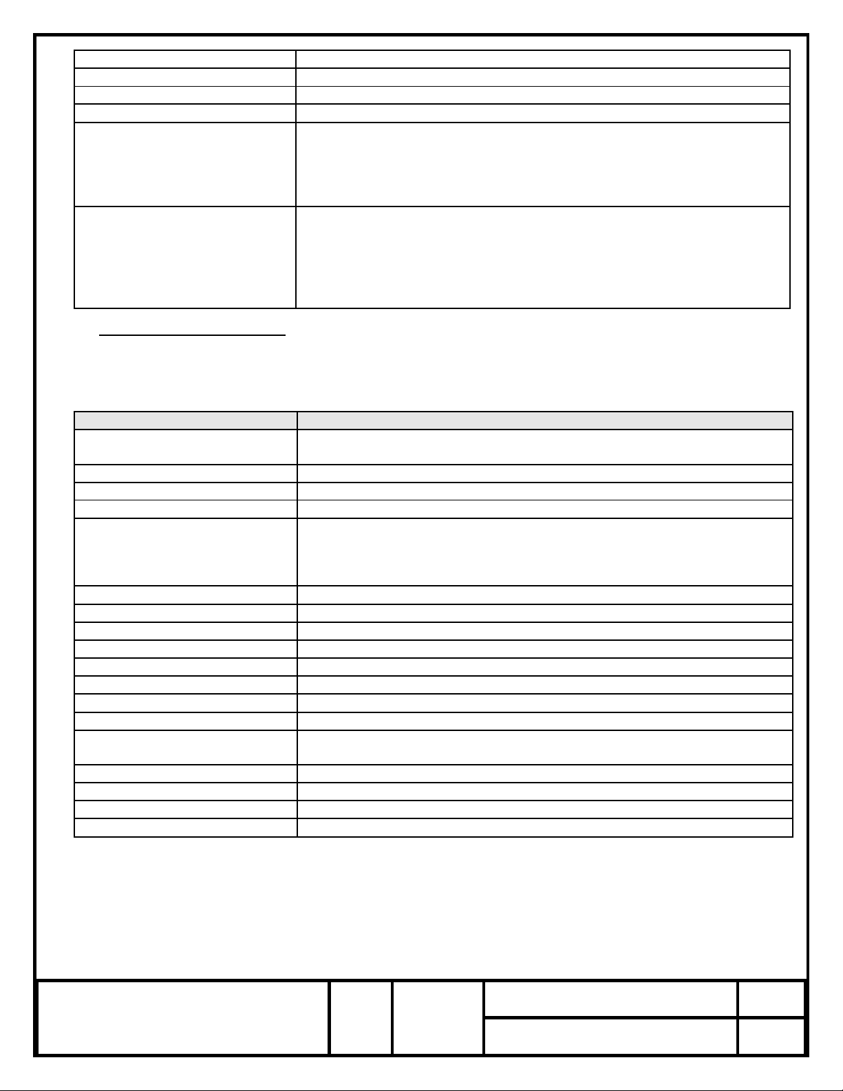
22X .100 TYP.
12
24
13
1
Q-TECH
PART NUMBER
FREQUENCY
D/C
USA
S/N
.210 MAX.
ESD SYMBOL FOR PIN NO. 1
24X .010 ± .002
.975 MAX.
1.275 MAX.
NON-ACCUMULATIVE
24X .015 ±.003
2X 1.100
24X .072 ± .007
2X .500 MIN.
2X .085 REF.
▀ PART NUMBER GENERATION
SERIES
Output type and
supply voltage
TEMPERATURE RANGE (°C)/ Max. Overall
Stability/ Min. Frequency Pulling
and Voltage Control Range
Level
FREQUENCY
(MHz)
4: SINE WAVE +3dBm ..5V
N: 0.....+50°C
±25 ppm
±50 ppm Vc=0.5..4.5V
E: Eng. Model
10……..350
5: SINE WAVE +7dBm ….12V
P: 0.....+70°C
±35 ppm
±70 ppm Vc=0.5..6.0V
M: Flight Model
6: SINE WAVE +7dBm ..15V
Q: 20…+70°C
±40 ppm
±80 ppm Vc=0.5..6.0V
R: 40…+85°C
±45 ppm
±90 ppm Vc=0.5..6.0V
U: -55.+125°C
±65 ppm
±130 ppm Vc=0.5..6.0V
QTV71:
24 Pin
Flat Pack
(See note 1 below)
1. Variations from standard specification are available, please contact factory.
EXAMPLE:
QTV715URM-100.000000 would be a Flight Model
version HF VCXO, 24 pin SMD flat pack, sine-wave 12 volts, overall
frequency stability (Overall Frequency stability (including operating temperature, ±5% Load Change, ±5% Supply
Voltage change, 10 year aging, and radiation) ±45 ppm over -40…+85°C, @ 50 MHz with frequency pulling range from
minimum of 90 ppm below center frequency at 0.5V to a minimum of 90 ppm above center frequency at 6V.
QTV715URE-100.000000
would be a Engineering Model version HF VCXO, 24 pin SMD flat pack, sine-wave 12 volts,
overall frequency stability (including operating temperature, ±5% Load Change, ±5% Supply Voltage change, 10 year
aging, and radiation)) ±45 ppm over -40…+85°C, @ 50 MHz with frequency pulling range from minimum of 90 ppm below
center frequency at 0.5V to a minimum of 90 ppm above center frequency at 6V.
FIGURE 1 INTERFACE CONTROL DRAWING
24 pin Flat-Pack
PIN NO.
DESIGNATION
1
Control Voltage
2 - 11
NC
12
Ground/Case
13
RF Output
14 - 23
NC
24
Supply Voltage
NOTES:
• Dimensions are in inches.
• Lead numbers are for reference only and
are not marked on the unit.
• A triangle symbol is marked on the corner of
the package to indicate Pin 1
• All pins with NC function may not be
connected as external tie or connections
(Pins may be connected internally).
 Loading...