

Page 1
REVISIONS
APPROVEDDATEDESCRIPTIONREVISION
Initial release-
A
Change General Specification reference to 401-0298-018. Paragraph 3.3.3 and Table III
changes for improved margin, design simplification. Corrected package drawing.
4/27/09
SPECIFICATION CONTROL DRAWING
UNLESS OTHERWISE
SPECIFIED DIMENSIONS ARE
IN INCHES.
TOLERANCES:
3 PLACE DECIMAL = .005
2 PLACE DECIMAL = .02
1 PLACE DECIMAL = .1
FRACTIONS = ± 1/16
ANGLES = 2 DEGREES
C.Hooper
B.Remtulla
T.Mitchell
Q-TECH CORPORATION
DATEPREPARED BY
10150 W. JEFFERSON BLVD.
CULVER CITY, CA. 90232-3510
Hybrid Voltage Controlled Crystal Oscillator,
DATECHECKED BY
DRAWING NO.
DATERELEASED BY
+5V, Class S, Detail Specification For
QT725C
SCALE:
CAGE CODESIZE
REV.
A
Sheet 1 of 5
NONE
51774A
Page 2
1 SCOPE
1.1 Scope.
This specification establishes the detail requirements for hybrid, hermetically sealed, crystal
oscillators for use in space flight missions.
1.2 Part number.
The part number shall be as specified in Table I herein.
2 APPLICABLE DOCUMENTS
2.1 Specifications and standards.
Unless otherwise specified, the following documents shall be applicable
to this specification to the extent specified herein.
SPECIFICATIONS
401-0298-018
Hybrid Crystal Oscillators, Class S, General Specification For
3 REQUIREMENTS
3.1 General requirements.
The individual item requirements shall be as specified in the General
Specification with the exceptions, modifications, and additions specified herein.
3.2 Approved manufacturer.
Hybrid crystal oscillators shall be supplied from the manufacturer specified in
paragraph 7.1 herein.
3.3 Design and construction.
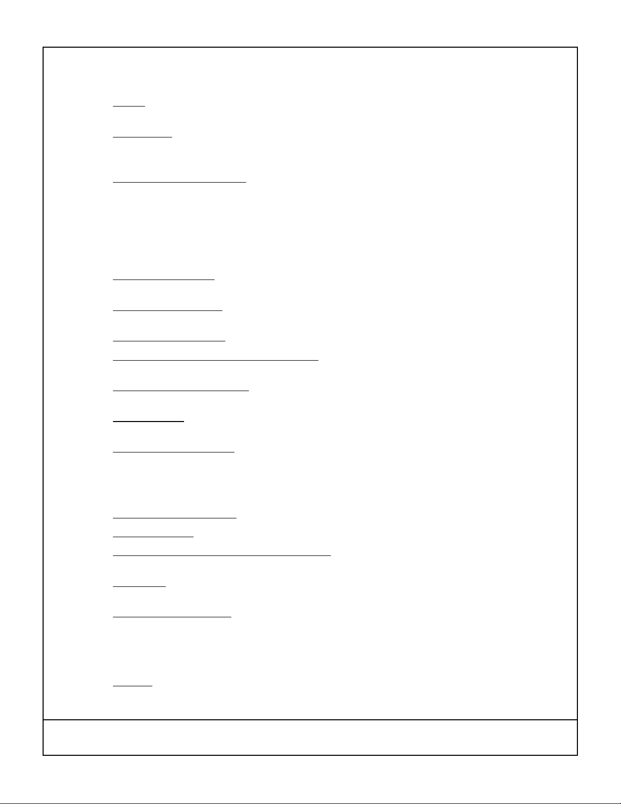
3.3.1. Outline dimensions and terminal connections.
be as shown in Figure 1 herein.
3.3.2. Package body and lead finish.
The package body and lead finish shall be gold in accordance with
MIL-PRF-38534.
The outline dimensions and terminal connections shall
3.3.3. Active Devices.
The microcircuit used in this part shall use CMOS technology and shall be from a
wafer proven to be radiation tolerant to 100 kRad (Si) total ionizing dose.
3.3.3.1 CMOS microcircuit usage.
For frequencies below 12 MHZ the output microcircuit shall be Intersil
Corporation 54ACS/HCS family, Silicon on Sapphire CMOS technology. For frequencies greater than
or equal to 12 MHZ, the CMOS microcircuit shall be 54AC00, see DSSC SMD 5962-87549. This
microcircuit is specified to be single event latchup free for LET up to 93 MeV-cm
manufacturer shall be ST Microelectronics Corporation.
3.4 Performance requirements.
3.4.1. Maximum ratings.
The maximum ratings shall be as specified in Table II herein.
3.4.2. Electrical performance characteristics and limits.
shall be in accordance with Table III herein.
3.4.3. Delta limits.
Except for frequency aging (refer to Table III), delta limits shall be in accordance with the
General Specification.
3.4.4. Total dose radiation limits.
Hybrid crystal oscillators supplied in accordance with this specification shall
be capable of meeting the performance requirements after being exposed to 100 krad total dose
radiation levels.
4 QUALITY ASSURANCE PROVISIONS
4.1 General.
The quality assurance provisions shall be in accordance with the General Specification with
the exceptions, modifications, and additions specified herein.
2
/mg. The
The electrical performance requirements and limits
Q-Tech Corporation
10150 W. Jefferson Blvd.
Culver City, CA. 90232
Specification number: QT725C rev A
Sheet 2 of 5
Page 3

4.2 Screening tests. The screening tests shall be in accordance with the General Specification.
4.3 Quality Conformance Inspection.
Quality Conformance Inspection shall be in accordance with the
General Specification and shall be required only when specified by the purchase order.
5 PACKAGING
5.1 Preservation, packaging and packing.
accordance with the General specification.
6 NOTES
6.1 Notes.
6.2 Ordering information.
The notes of the General Specification are applicable to this drawing.
The procuring activity shall advise Q-Tech Corporation at the time of Request
for Quotation if quality conformance inspection is to be required.
6.3 Part number
. QT725 C B M - 16.000000 MHZ
Model #
Supply voltage: C: + 5.0 volts
Temp stability - see Table I
Screening: E: engineering model; M: flight model
Frequency (8 digits)
TABLE I. STABILITY / TEMPERATURE OPTIONS
B
D
E
Hybrid crystal oscillators shall be prepared for delivery in
TEMP STABILITYOPTION
± 50 PPM, - 55 °C TO + 125 °C
± 40 PPM, - 55 °C TO + 105 °C
± 30 PPM, - 40 °C TO + 85 °C
7 SOURCE OF SUPPLY
7.1 Approved manufacturer.
Q-Tech Corporation
10150 W. Jefferson Blvd.
Culver City, Ca. 90232 U.S.A.
Supply voltage
Control voltage
Operating temperature
Package thermal resistance
Q-Tech Corporation
10150 W. Jefferson Blvd.
Culver City, CA. 90232
TABLE II. MAXIMUM RATINGS
CC
C
C
θjc
UnitsMaxMinSymbolParameter
Volts70V
Volts70V
ºC125-55T
ºC150-65TstgStorage temperature
ºC/seconds250/10Lead solder temperature/time
ºC/W50
Specification number: QT725C rev A
Sheet 3 of 5
Page 4

INITIAL FREQUENCY ACCURACY
FREQUENCY DEVIATION
LINEARITY
INPUT CURRENT
Measured without load at 5.5 Vdc
RISE / FALL TIME
STARTUP TIME
TABLE Ill. ELECTRICAL PERFORMANCE CHARACTERISTICS
TEST CONDITIONS 2/,3/ELECTRICAL PARAMETER
Vc = 2.5 volts (center)
T = +25°C ± 2 °C
0 < Vc < 5
-55°C < T < +125°C
Output frequency:
Less than 12 MHZ
Output frequency:
80 MHZ - 100 MHZ
70 °C ± 3°CFREQUENCY AGING (AFTER 1 YEAR)
NOTES
NOTESLIMITS
UNITSMAX.NOM.MIN.
3FREQUENCY RANGE AVAILABLE
See Table IFREQUENCY/TEMPERATURE STABILITY
12080TUNING SCALE FACTOR, AVERAGE
DCMODULATION BANDWIDTH
50CONTROL VOLTAGE INPUT IMPEDANCE
VCC x 0.9OUTPUT VOLTAGE - LOGIC "1"
MHz100
Vdc50CONTROL VOLTAGE (Vc) RANGE
PPM/VOL
T
-PositiveTRANSFER FUNCTION
%±10
kΩ
Vdc5.554.5SUPPLY VOLTAGE
mA12
mA3012 MHZ - 59.99 MHZ
mA5060 MHZ - 100 MHZ
N/ASquarewaveOUTPUT WAVEFORM
%60/40DUTY CYCLE
ppm±1.570 °C ± 3°CFREQUENCY AGING (AFTER 30 DAYS)
ppm±10
ms10
1/
4/PPM± 25
4/PPM± 110
5/
8/kHz10
8/
7/-CMOSLOAD
6/VdcVCC x 0.1OUTPUT VOLTAGE - LOGIC "0"
6/Vdc
7/nS7Below 12 MHZ
7/nS3.512 MHZ - 80 MHZ
7/nS2.5
1. The limit for frequency/temperature stability shall be referenced to the output frequency at 25 °C with Vc = any constant value
within the control voltage range.
2. Unless otherwise specified, the limits are over the full operating temperature range and under specified load conditions.
3. Unless otherwise specified, all measurements are in accordance with MIL-PRF-55310.
4. Referenced to nominal output frequency. Up to 30 days after shipment (does not include Aging). Center tuning voltage is
defined as Vc = 2.5 volts.
5. Slope of linear estimate (least squares) for 0 < Vc < 5V.
6. Voltage values are with respect to network ground terminal.
7. A standard CMOS load of 10 kOhm || 15 pF shall be used. See MIL-PRF-55310/26 for CMOS waveform measurement
definitions.
8. Tested at room temperature only.
Q-Tech Corporation
10150 W. Jefferson Blvd.
Culver City, CA. 90232
Specification number: QT725C rev A
Sheet 4 of 5
Page 5

NOTES:
1. Dimensions are in inches.
2. Lead numbers are for reference only and are not marked on the unit.
3. All pins with function NC may not be connected as external tie or connections, except they may be tied to
Ground
.
TERMINAL CONNECTIONS
CONNECTIONTERMINAL NO.CONNECTIONTERMINAL NO.
OUTPUT11Vc1
13N/C3
GND/CASE *12N/C2
V
CC
N/C14N/C4
GND/CASE *15N/C5
N/C16N/C6
N/C17N/C7
N/C18N/C8
N/C19N/C9
N/C20GND/CASE10
* Additional optional Ground connections are included only when microcircuit used is 54AC00 (see
paragraph 3.3.3.1), and may be connected to circuit ground plane for minimum overshoot/ringing
when driving capacitive loads.
FIGURE 1. PACKAGE DIMENSIONS AND TERMINAL CONNECTIONS
Q-Tech Corporation
10150 W. Jefferson Blvd.
Culver City, CA. 90232
Specification number: QT725C rev A
Sheet 5 of 5
 Loading...