

Page 1

SF-1
Subwoofer
Filter
Owner’s Manual
9
FPO
Rev. A
Page 2

10
Page 3
SF-1 SUBWOOFER FILTER
INTRODUCTION
The SF-1 Subwoofer Filter is an upper slot accessory for QSC MXa Series amplifiers, which feature Level
One Open Input Architecture. The accessory mounts in the back of the amplifier above the standard input
panel.
Ideal for adding subwoofer amplification to an existing full-range system, the SF-1 offers adjustable and
selectable low-pass filtering for both channels of the amplifier, in addition to adjustable high-pass subsonic
filtering. The filter slopes are 12 dB per octave, and the filter frequencies are programmable via provided
SIP resistor networks.
A slide switch, SW1, allows you to configure the SF-1 with a low-end “boost” which provides a suitable
equalization for use with B6 speaker enclosures. A 10-position DIP switch, SW2, affords you the versatility
of setting the accessory in many different configurations, such as mono summing and single channel
bypass. The configuration process is detailed below.
The use of the SF-1 for cinema subwoofer installations can reduce the chance of speaker damage by digital
soundtracks. Low frequency information, below the box tuning frequency, can destroy speakers at power
levels far below their rated capacity. The SF-1 can remove these damaging frequencies and also provide
the needed equalization to flatten and extend the response of popular cinema subwoofers. These include:
Electro-Voice models TL880D, TL550D, TL3512, TL440 and JBL 4645 and 4645B.
Existing cinema surround systems typically have limited low frequency response. New digital surround
formats now have full-range surround channels that extend frequency response much lower than previous
optical surround formats. The SF-1 may be used to protect surround speakers from damage, due to
excessive low frequency operation. It is desirable, however, to eventually upgrade the capability of the
surround systems to handle the increased power and low frequency response requirements of digital
soundtracks.
25
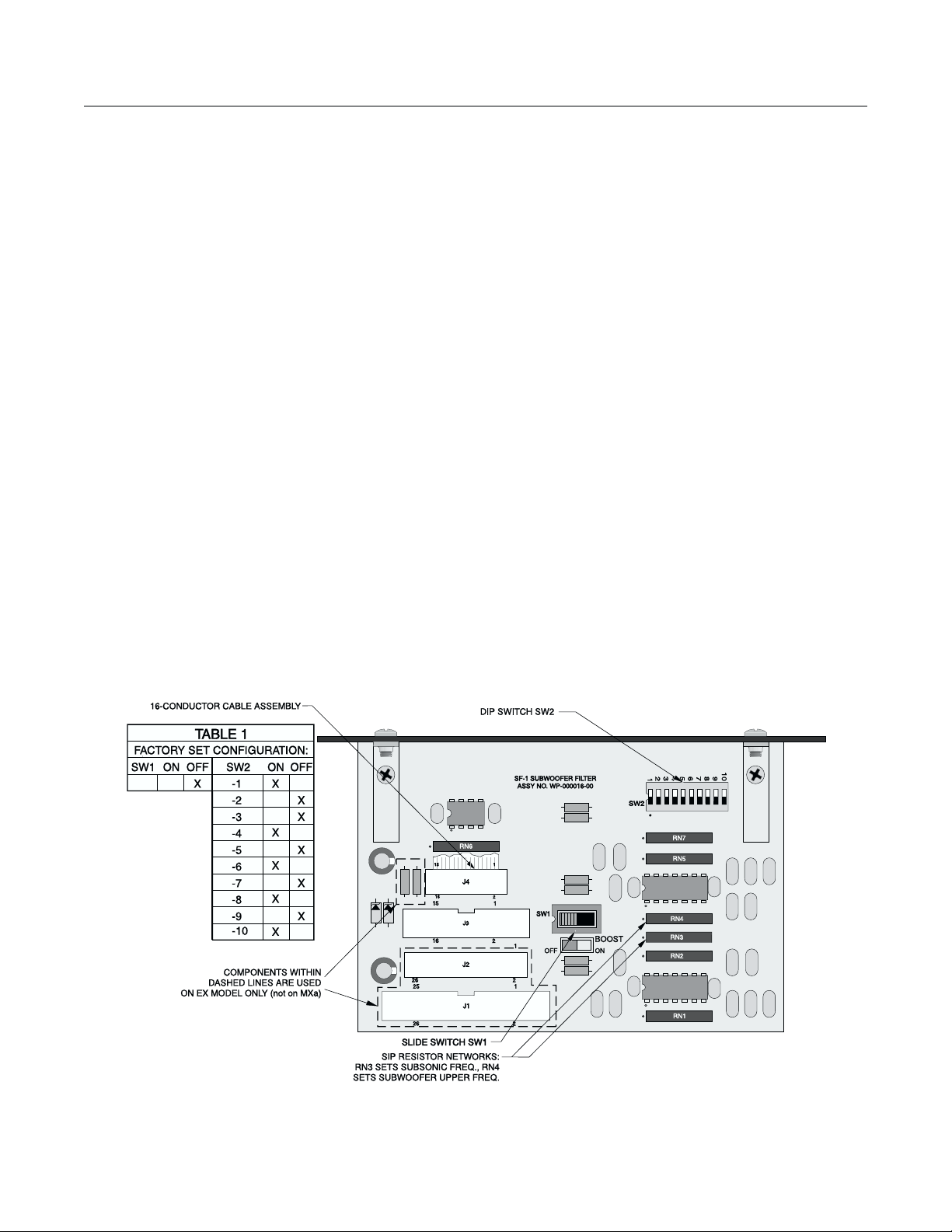
Figure 1
Figure 1 shows where the pertinent switches, resistor networks, and connectors are located on the SF-1
board.
1
Page 4

CONFIGURATION
SETTING THE SUBSONIC FILTER FREQUENCY
The subsonic (highpass) filter on Channel 1 cannot be bypassed, and Channel 2 should only be bypassed
in the bridged mono mode. Plug-in SIP resistor network RN3 sets the high-pass frequency for both channels
1 and 2. Table 2 shows the resistor value to be used for the frequency you desire. Typical subsonic
frequencies available with the provided SIP resistor networks are 20, 25, 32, 35, 40, 50, 63, and 80 Hz.
Consult your subwoofer manufacturer if you are unsure of what frequency to use.
If you desire a 6-dB boost at the low end of the subwoofer frequency range, set the slide switch SW1 to “ON”;
otherwise set it to “OFF.” Such a boost is popular with users of Electro-Voice B6 subwoofer enclosures.
TABLE 2
Frequency Resistor Network Value (RN3 or RN4)
20 82K Factory set for RN3
25 68K
32 56K
35 47K
40 39K
50 33K
63 27K
80 20K
100 18K
135 12K
160 10K
200 8.2K
250 6.8K Factory set for RN4
SETTING THE SUBWOOFER UPPER FREQUENCY LIMIT
The low-pass filter sets the upper limit of the subwoofer frequency range. Plug-in SIP resistor network RN4
sets the low-pass frequency for both channels 1 and 2. Table 2 shows the resistor value to be used for the
frequency you desire. Typical frequencies available with the provided SIP resistor networks are 100, 135,
160, 200, and 250 Hz. Consult your subwoofer manufacturer if you are unsure of what frequency to use.
Whatever frequency you choose should be higher than that of the subsonic filter.
SETTING DIP SWITCH SW2
Determine the configuration you desire and set the DIP switches as described below.
Positions 1 through 4 and 9 and 10
First, decide whether you need “Mono Sum” or “Stereo” operation. This will determine the settings of
positions 1 through 4 and 9 and 10 of DIP switch SW2.
• Mono Sum
Because it is difficult for listeners to sense directionality of low audio frequencies, many subwoofer
systems are set up for monaural operation, with both channels summed together. For mono
summed operation, set the amplifier mode switch to “STEREO” and SW2 as follows:
Position 1 OFF
Position 2 ON
Position 3 ON
Position 4 OFF
Position 9 OFF
Position 10 ON
Continue to “Positions 5 through 8” and set those switches to engage both channels’ low-pass
filtering.
2
Page 5

• Stereo, Bridged Mono, and Parallel Mono
If the two subwoofer channels are to carry different or independent program material, as in stereo
or bridged mono, set the SF-1 for “Stereo” operation. Use this also for parallel mono operation from
a single program signal source. For stereo, bridged mono, or parallel mono operation, set the
amplifier mode switch to “STEREO,” “BRIDGED,” or “PARALLEL,” respectively, and SW2 as
follows:
Position 1 ON
Position 2 OFF
Position 3 OFF
Position 4 ON
Position 9 ON if bridged mono, OFF otherwise
Position 10 OFF if bridged mono, ON otherwise
Positions 5 through 8
Next determine whether you wish to bypass the low-pass filtering on either channel for use with a full-range
speaker system. This will determine the settings of positions 5 through 8 of DIP switch SW2.
• Channel 1: bypass or engage low-pass?
If you’re connecting a full-range speaker to Channel 1, bypass its low-pass filtering. If you’re
connecting it to a subwoofer, engage the filtering. Typical cinema subwoofers are an exception, the
low pass filter should be bypassed in this application, as cinema processors typically perform this
function.
Position 5 ON if bypassed, OFF if engaged
Position 6 OFF if bypassed, ON if engaged
• Channel 2: bypass or engage low-pass?
Likewise, if you’re connecting a full-range speaker to Channel 2, bypass its low-pass filtering, and
if you’re connecting it to a subwoofer, engage the filtering. Typical cinema subwoofers are an
exception, the low pass filter should be bypassed in this application, as cinema processors typically
perform this function.
Position 7 ON if bypassed, OFF if engaged
Position 8 OFF if bypassed, ON if engaged
CAUTION: On DIP switch SW2, the switch pairs, i.e., positions 1 and 2, 3 and 4, 5 and 6, 7 and 8, and
9 and 10, are complementary. That is, if position 1 is “ON,” 2 must be “OFF” and vice versa; if 3 is
“ON,” 4 must be off, and so on. To prevent improper operation of the SF-1 and the amplifier, and
possible damage that may result to the accessory, amplifier, or loudspeaker, check your switch
settings carefully before you install the SF-1 in your amplifier.
3
Page 6

INSTALLATION
Before installing the SF-1, disconnect the amplifier’s power cable from the AC mains.
1. Position the amplifier so that the rear panel is facing you. Locate the input panel and the blank
accessory panel above it.
2. Remove the four mounting screws—the two holding the blank panel and the two holding the
standard input panel. Remove the blank panel (which the SF-1 will replace) and carefully pull the
input panel out from the amplifier chassis
3. Disconnect the ribbon cable from the circuit board of the input panel.
4. Position the SF-1 so that its component side faces the ribbon connector of the input panel card.
5. Connect the included short ribbon interface cable from the SF-1 to the ribbon connector on the input
panel card. The ribbon cable attaches to J4 on the SF-1
The connectors are keyed; make sure they line up properly and the ribbon cable is not twisted before
you carefully press them together. Be sure to press the connectors together firmly.
6. Connect the ribbon cable from the amplifier (the cable you disconnected from the input panel card)
to the SF-1 circuit board, using J3
the cable should be toward the right, from your point of view. Newer amplifiers have a keyed
connector on the ribbon cable. Press the connectors together firmly.
7. Tuck the interface ribbon cable neatly between the SF-1 and the input panel card. Insert the two
cards carefully into the amplifier chassis and secure them with the four screws you removed in step
2. Don’t over-torque the screws
(figure 2c)
(figure 2d)
(figure 2a)
. Make sure the cable is not twisted; the red stripe on
.
.
(figure 2b)
.
a
b
c
Figure 2
4
d
Page 7

SPECIFICATIONS
SIGNAL TO NOISE RATIO (22 Hz to 22 kHz): 103 dB
TOTAL HARMONIC DISTORTION <0.1 %
CROSSTALK 70 dB below rated power within passband
CMRR: better than 50 dB
FILTER TYPE second-order butterworth, Q=0.707
DIP SWITCH FUNCTIONS
(LPF and unboosted subsonic filter)
second-order, +6 dB boost, Q=2
(boosted subsonic filter)
TABLE 3—DIP SWITCH SW2
Mode 1 2 3 4 5 6 7 8 9 10
Mono Sum OFF ON ON OFF
Stereo ON OFF OFF ON
Bypass Channel 2 (bridged mono) ON OFF
Engage Channel 2 OFF ON
Bypass Channel 1 LPF ON OFF
Bypass Channel 2 LPF ON OFF
Engage Channel 1 LPF OFF ON
Engage Channel 2 LPF OFF ON
BLOCK DIAGRAM
5
Page 8

APPLICATION NOTES
For cinema surround channels and subwoofers that do not require an EQ boost, use the following switch
settings.
SW1 slide switch- BOOST OFF
SW2 DIP switch
Position 1 ON
Position 2 OFF
Position 3 OFF
Position 4 ON
Position 5 ON
Position 6 OFF
Position 7 ON
Position 8 OFF
Position 9 ON if bridged mono, OFF otherwise
Position 10 OFF if bridged mono, ON otherwise
The high pass filter frequency for non-boosted subwoofers, such as the JBL 4645 and Electro-Voice
systems NOT being used in the step-down box tuning mode, should be selected at about 0.8 times the box
tuning frequency of the subwoofer. A frequency of 20, 25, or 32 Hz will usually give the best results. Select
an appropriate SIP resistor pack and install it in position RN3. Consult your speaker manufacturer for more
details about your specific subwoofer system. Surround channels may benefit from the use of a high pass
filter at 80 Hz, also installed in position RN3.
For cinema subwoofers that require an EQ boost, use the following switch settings.
SW1 slide switch- BOOST ON
SW2 DIP switch
Position 1 ON
Position 2 OFF
Position 3 OFF
Position 4 ON
Position 5 ON
Position 6 OFF
Position 7 ON
Position 8 OFF
Position 9 ON if bridged mono, OFF otherwise
Position 10 OFF if bridged mono, ON otherwise
The high pass filter frequency for boosted, B6 subwoofer alignments should be selected according to the
recommendations of the speaker manufacturer. Select an appropriate SIP resistor pack, for the desired
boost frequency, and install it in position RN3. Listed below are some suggested filter frequencies for
popular subwoofers, consult your speaker manufacturer for more details about your specific subwoofer
system. A variance of +/- 5% from the exact boost frequency will have very little effect on the performance
of the system.
Electro-Voice:
JBL:
TL880D 25 Hz
TL550D 32 Hz
TL3512 32 Hz
TL440 32 Hz
4645B 25 Hz
6
Page 9

APPENDIX A: WARRANTY & DISCLAIMERS
DISCLAIMER
QSC Audio Products, Inc. is not liable for any damage to speakers, amplifiers, or any other equipment that
is caused by negligence or improper installation and/or use of the SF-1 Subwoofer Filter.
PRODUCT WARRANTY
QSC Audio Products, Inc. guarantees the SF-1 Subwoofer Filter to be free from defective material and/or
workmanship for a period of three years from date of sale, and will replace defective parts and repair
malfunctioning products under this warranty when the defect occurs under normal installation and use—
provided the unit is returned to our factory via prepaid transportation with proof of purchase (sales receipt).
This warranty provides that examination of the returned product must disclose, in our judgment, a
manufacturing defect. This warranty does not extend to any product which has been subject to misuse,
neglect, accident, improper installation, or where the date code has been removed or defaced.
APPENDIX B: TECHNICAL ASSISTANCE & SERVICE
Servicing your unit requires a trained technician capable of performing the type of service you need. There
are no user serviceable components inside your unit and the danger of electric shock exists. Additionally,
some of the components in your unit are QSC specific parts that require QSC replacements. Comprehensive service manuals for some models are available at QSC.
TECHNICAL ASSISTANCE
If you suspect that your amplifier is defective, check your system configuration and amplifier settings to
determine the origin of the problem. In many cases, incorrect audio interfacing, poor cabling, or other
system level impairments are the cause of problems in audio systems. For technical assistance beyond
the information given in this manual, the QSC Technical Services department may be contacted.
FACTORY SERVICE
In the event that your amplifier does need factory service, you may reach the QSC Technical Services
department for return instructions. A Return Authorization (RA) number must be obtained from the QSC
Technical Services department. QSC may not account for products that are returned without a Return
Authorization number.
Product Return Guidelines
1. Pack the product well for protection during shipment. QSC will provide the factory packaging free of
charge upon request.
2. Include a copy of the sales receipt, your name, return address, phone number, and defect description
with your return correspondence.
3. Call the QSC Technical Services department for a Return Authorization number.
4. Mark the Return Authorization number on the outside of the packaging.
5. Ship the product prepaid to QSC Audio Products. We recommend United Parcel Service (UPS).
7
Page 10

QSC TECHNICAL SERVICES DEPARTMENT
1675 MacArthur Blvd
Costa Mesa, CA 92626
Telephone: (800) 772-2834
(714) 957-7150
(714) 754-6175
Fax: (714) 754-6173 Bulletin Board: (714) 668-7567
(800) 856-6003
INTERNATIONAL SERVICING
For QSC products that are purchased outside of the United States, service must be referred to the distributor
or dealer from where the product was purchased. There are numerous service centers in many countries.
The service centers in your country may be located by your dealer, distributor, or by contacting QSC
Technical Services.
APPENDIX C: IMPORTANT ADDRESS AND TELEPHONE
INFORMATION
Factory address:
QSC Audio Products, Inc.
1675 MacArthur Boulevard
Costa Mesa, California 92626-1468 USA
Factory telephone numbers:
Main Number (714) 754-6175
Sales Direct Line (714) 957-7100
Sales (800) 854-4079
Sales & Marketing FAX (714) 754-6174
Customer Service (714) 957-7150
Customer Service (800) 772-2834
Customer Service FAX (714) 754-6173
QSC OnLine (714) 668-7567
(toll-free in U.S.A. only)
(toll-free in U.S.A. only)
(800) 856-6003
8
Page 11

11
Page 12

QSC AUDIO PRODUCTS, INC. 1675 MacArthur Blvd., Costa Mesa, CA 92626 USA Ph (714) 754-6175 Fax (714) 754-6174
“QSC” and the QSC logo are registered with the U.S. Patent and Trademark Office.
Email INFO@qscaudio.com Web http://www.qscaudio.com
12
 Loading...