

Page 1
Service Bulletin
Title: DSP-4 RS-232 Communication/Turn-Off Thump
Bulletin #: DSP0009
Issue Date: July 27, 2006
Models Affected: DSP-4
Bulletin Revision: Rev. A
Production Range: 05/2001 through 05/2006 (serial numbers 0501xxxxx–0506xxxxx)
Description
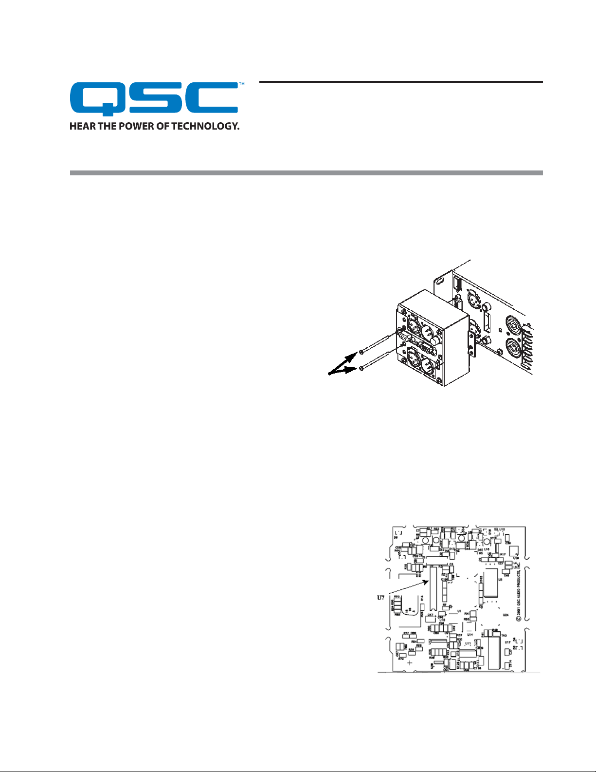
When a DSP-4 unit is mounted directly to a QSC single DataPort equipped amplifier and the two long screws shown in Figure 1 are
tightened, the torque bends the two internal PCB boards slightly. This causes the leads from U7 (a 20-pin DIP microcontroller) to
touch the top of capacitors C42 and C45, causing communication and audio problems. To correct this inadvertent connection, trim all
20 of U7’s lead pins.
Symptoms
When mounted directly to a QSC single DataPort-equipped
amplifier and the two #4-40 screws shown in Figure 1 are tightened, the DSP-4 may exhibit any of these problems:
• Loss of RS-232 communication with the computer and the
Signal Manger software
• A thump on the output signals during turn off.
• A buzz in the output signals.
Instructions
Tools and materials required:
• #2 Philips screwdriver
• Small boxes or compartments (to hold assorted screws during
disassembly)
• Small diagonal cutters
Caution: Take appropriate anti-static measures to guard against damage from electrostatic discharge (ESD).
Procedure: Trimming the leads on the microcontroller U7
Gaining access to the IC
1. Disconnect the DSP-4 from the amplifier.
2. Remove all 14 screws on the front panel of the DSP-4. Turn the DSP-4 on its
side and remove the other two screws, then flip the DSP-4 over (Data Port
receptacle side) and remove the remaining ones. Note that there are four
different screw sizes.
3. Gently and carefully pull the chassis apart and remove the printed circuit
board (PCB) assembly.
4. Separate the two PC boards and locate the one with the QSC part number
that begins with
5. Locate the microcontroller U7. See Figure 2.
6. Use small diagonal cutters to trim all 20 leads of U7.
WP-000411-
.
Figure 1. The problems may occur when these two screws
are tightened.
Figure 2. Locate the microcontroller U7.
Continued on next page
➜
1DSP0009 rev. A.
Page 2
Reassembly
7. Reassemble the two PCBs by
connecting the two headers J10 and
J1.
8. Insert the PCB assembly into the
chassis, while making sure the power
and signal LEDs are lined up correctly
in their appropriate openings.
9. Place the cover on the chassis. Insert
and tighten all 18 screws.
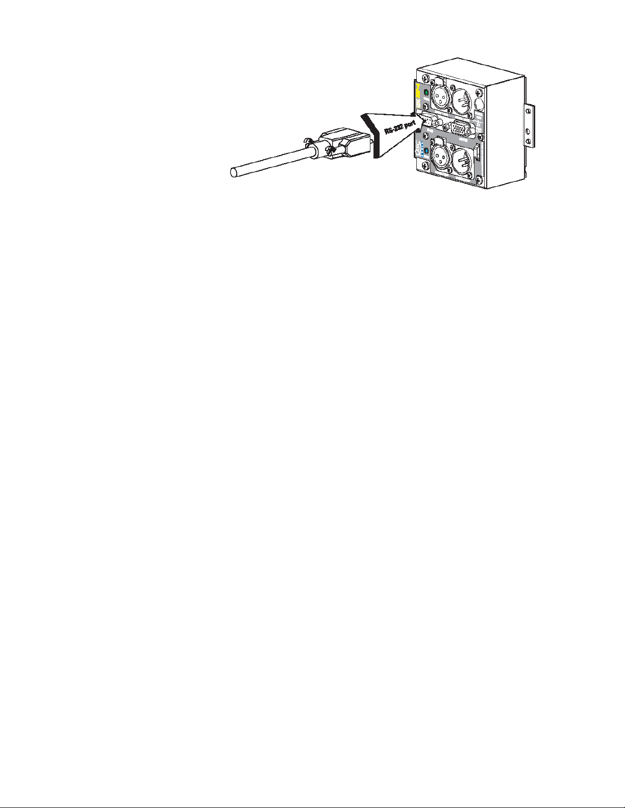
Figure 3. Connect the DSP-4 to the computer via the 9-pin serial port.
Procedure: Testing the DSP-4
1. Mount the DSP-4 to the rear of a QSC CX, DCA, PL2, or SRA Series amplifier equipped with a single DataPort (Figure 1).
2. Install the two long screws next to the DataPort.
3. Install the #8-32 screw to secure the right side of the DSP-4 to the amplifier.
4. Plug a 9-pin serial cable into the DSP-4’s RS-232 connector (Figure 3).
5. Plug the other end of the serial cable into an available COM port on your computer. Tighten the retaining screws.
6. Turn the amplifier on and confirm that the DSP-4 has power.
7. Launch the Signal Manager application.
8. Confirm that the DSP-4 can communicate with Signal Manager.
Contact information
This bulletin is available for download from the Service Bulletins page in the
http://www.qscaudio.com/support/technical_support/bulletins.htm. If you need any further information regarding this
service procedure, please contact QSC Technical Services at the addresses or numbers below.
Telephone:
Fax:
E-mail:
Web sites:
Postal and parcel address:
1-800-772-2834 (within USA only)
+1 (714) 957-7150
+1 (714) 754-6173
tech_support@qscaudio.com
www.qscaudio.com (product info/support)
www.qscstore.com (on-line accessory and replacement component sales)
QSC Audio Products, Inc.
Technical Services Group
1665 MacArthur Blvd.
Costa Mesa, CA 92626 USA
2 DSP0009 rev. A.
Tech Support
section of the QSC Audio Web site:
 Loading...