

Page 1
Hardware Manual
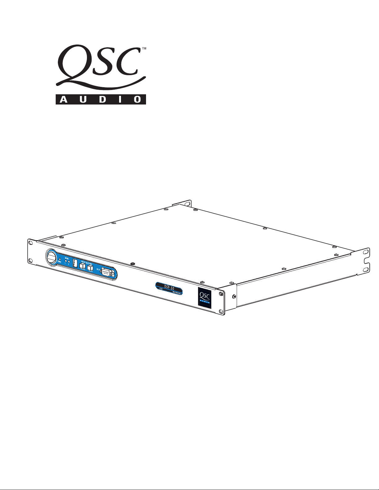
DSP-30
2.2 XLR
Rack-mount, 2 Channel Digital Signal Processor
*TD-000097-00*
TD-000097-00
Rev.B
1
Page 2
WARNING!
WHILE QSC HAS ENDEAVORED TO DEVELOP AND PRODUCE THE MOST DEPENDABLE AND ROBUST DIGITAL SIGNAL
PROCESSOR (DSP) AUDIO PRODUCT FOR YOUR USE, DUE TO THE UNLIMITED AND POTENTIALLY DESTRUCTIVE (TO THE
SOUND SYSTEM) CONFIGURATIONS THAT MAY BE APPLIED TO THE DSP BY THE USER, QSC CANNOT BE HELD RESPONSIBLE
FOR DAMAGES RESULTING FROM ANY DEVIATION OR FAILURE BY THE USER TO STRICTLY FOLLOW THE RECOMMENDA-
TIONS SET FORTH IN THE OWNER’S MANUAL FOR THE INTEGRATION OF THE DSP AND SIGNAL MANAGER SOFTWARE WITH
YOUR SOUND SYSTEM.
ALL RISKS ATTENDANT TO INTEGRATION OF USER-CONFIGURABLE DSP PRODUCTS WITH YOUR SOUND SYSTEM ARE
ASSUMED BY YOU. WHILE QSC STRIVES TO SUPPLY THE HIGHEST QUALITY TECHNICAL SOLUTIONS FOR DIGITAL SIGNAL
PROCESSING, IN NO EVENT WILL QSC OR ITS SUPPLIERS BE HELD LIABLE FOR ANY DAMAGES, CONSEQUENTIAL,
INCIDENTAL, OR OTHERWISE, INCLUDING ANY CLAIMS FOR LOST PROFITS AND/OR SAVINGS RESULTING FROM ANY
ATTEMPTED INTEGRATION OF THE DSP AND SIGNAL MANAGER SOFTWARE WHICH DOES NOT STRICTLY ADHERE TO THE
MANUAL’S RECOMMENDATIONS.
IMPORTANT SAFETY INFORMATION: PLEASE REVIEW!
EXPLANATION OF GRAPHICAL SYMBOLS
Federal Communications
Commission (FCC)
Information
NOTE: This equipment has been tested
and found to comply with the limits for a
Class B digital device, pursuant to Part 15
of the FCC Rules. These limits are de-
signed to provide reasonable protection
against harmful interference in a com-
mercial installation. This equipment gen-
erates, uses, and can radiate radio fre-
quency energy and, if not installed and
used in accordance with the instructions,
may cause harmful interference to radio
communications. Operation of this equip-
ment in a residential area is likely to
cause harmful interference, in which case
the user will be required to correct the
interference at his or her own expense.
The lightning flash with arrowhead symbol, within an equilateral
triangle, is intended to alert the user to the presence of uninsulated “dangerous voltage” within the product’s enclosure that
may be of sufficient magnitude to constitute a risk of electric
shock to humans.
The exclamation point within an equilateral triangle is intended
to alert the users to the presence of important operating and
maintenance (servicing) instructions in the literature accompanying the product.
CAUTION
RISK OF ELECTRIC SHOCK
DO NOT OPEN
CAUTION: To reduce the risk of electric shock, do not remove
the cover. No user-serviceable parts inside. Refer servicing to
qualified service personnel.
WARNING: To prevent fire or electric shock, do not expose this
equipment to rain or moisture.
SAFEGUARDS
Electrical energy can perform many useful functions. This unit
has been engineered and manufactured to assure your personal
safety. Improper use can result in potential electrical shock or fire
hazards. In order not to defeat the safeguards, observe the
following instructions for its installation, use and servicing.
2
Page 3

Table of Contents
INTRODUCTION Product Overview..................................................................4
Front and Rear Panel Illustrations and Dimensions.................4
INSTALLATION Unpacking..................................................................................................6
What is Included...................................................................................6
Mounting............................................................................................6
Connections:
Balanced Audio Connector Pinouts........................7
Unbalanced Audio Connector Pinouts................................8
Audio Inputs and Outputs..........................................9
RS-232 Port....................................................................10
System Requirements...........................................................................11
Software Installation...........................................................................11
USE Control, Indicator, and Connector Descriptions..................12
General Use Guidelines.................................................................14
Presets....................................................................................15
How to save presets into the DSP-30...........................................15
How to recall Presets ...............................................................16
Lockout feature use.......................................................................17
Contact closure Feature .............................................................18
RS-232 pinout.........................................................................19
Application Example....................................................................20
SPECIFICATIONS.......................................................................................................................................................22
ARCHITECT’S & ENGINEER’S SPECIFICATION..............................................................................................24
QSC INFORMATION Maintenance, Warranty & QSC Contact Information................................25
© Copyright 2001, QSC Audio Products, Inc.
QSC® is a registered trademark of QSC Audio Products, Inc., Costa Mesa, CA
“QSC” and the QSC logo are registered with the U.S. Patent and Trademark Office
3
Page 4
Introduction: Overview and Illustrations
Overview
The DSP-30 and Signal Manager software combine easy-touse, customizable, two-channel DSP with simple operatingmode selection that requires only two buttons to operate. It
can be used with all amplifiers and is housed in a 1-RU , 19-inch
rack-mount steel chassis. Sampling frequency is 48 kHz. with
24-bit resolution. Dynamic range is greater than 93dB. It is
absolutely rugged and dependable in the spirit of all QSC
professional audio products and fully suited for the rigors of
touring use.
Processing capabilities of the DSP-30 include compressors,
limiters, delays, parametric EQ, high/low pass filters, high/low
shelf filters, test signal generators (sine-wave, pink- and
white-noise), splitters/mixers, polarity reversal, gain/attenuation, and metering. A feature called “Predictive Delay” enables the DSP-30’s compressors and limiters to produce less
signal distortion than their analog counterparts, especially for
fast attack times. Predictive delay adds time delay to the signal
path and must be accounted for to maintain proper time
allignment. Using the Signal Manager software, predictive
delay may be turned on or off; when on, it will provide time
delay information to the operator.
The DSP-30 provides powerful signal processing while keeping operation as simple. Preset operating modes are userselectable by scrolling through the list of numbered Presets on
the front panel display and selecting. The DSP-30 will mute,
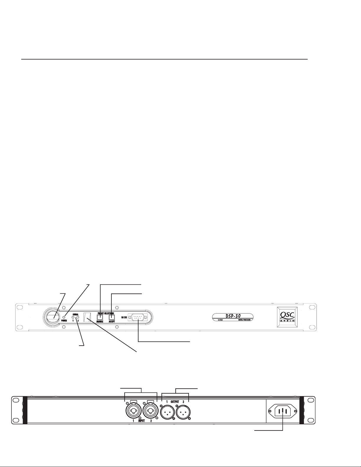
Front Panel
reconfigure, and unmute in a fraction of a second, providing
smooth transitions free of thumps, clicks and other undesirable audio artifacts. The contact closure input feature allows
for instantaneous gain changing and other programmable
uses.
Use the QSC Signal Manager software to create the preset
configurations. Please refer to page 11 for computer system
requirements and software installation guidelines. For instructions for creating a simple signal processing chain, refer
to the software help file. QSC’s Signal Manager software
provides an easy-to-use graphical user interface where DSP
“objects” are placed onto a workspace and interconnects are
drawn. This interface allows almost infinite configuration
possibilities.
Signal Manager transfers the preset data to the DSP-30
through a serial data cable. The cable connects between the
computer’s COM port and the DSP-30’s RS-232 port. Once the
presets have been loaded, connection to the computer is no
longer required. This feature allows essentially tamper-proof
DSP setup. Stored presets can be recalled using the front
panel Select button. Modification of stored presets, or the
creation of new presets can be implemented by connecting a
computer and loading the new presets into the DSP.
The DSP-30 will provide many years of reliable, professional
quality signal processing. From all of us at QSC Audio Products, “Thank you.”
Power ‘on’ indicator LED
Power switch
Signal indicator LED’s
Rear Panel
4
Browse button
Accept button
RS-232 connector
Multi-segment LED numeric display
Input Connectors Output Connectors
AC Power Connector
Page 5
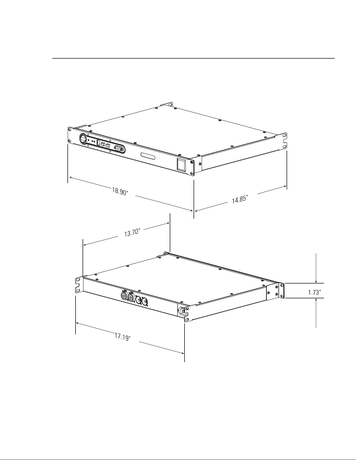
Introduction: Illustrations and Dimensions
Dimensions
5
Page 6
Installation: Unpacking and Mounting
Unpacking
There are no special unpacking precautions. However, it is recommended you keep the original packing material for reuse
in the rare event that service be required. If service is required and the original packing material is not available, ensure
that the unit is adequately protected for shipment (strong box of appropriate size , sufficient packing material to prevent
load-shifting or impact damage).
What is included in the carton:
Item Description Quantity
1- DSP-30 Digital Signal Processor 1
2- Self-adhesive rubber feet 4
3- Hardware Manual (this document) 1
4- Signal Manager Software CD 1
5- IEC Power Cord 3 x #18 AWG 1
6- RS-232 cable (6 ft.) 1
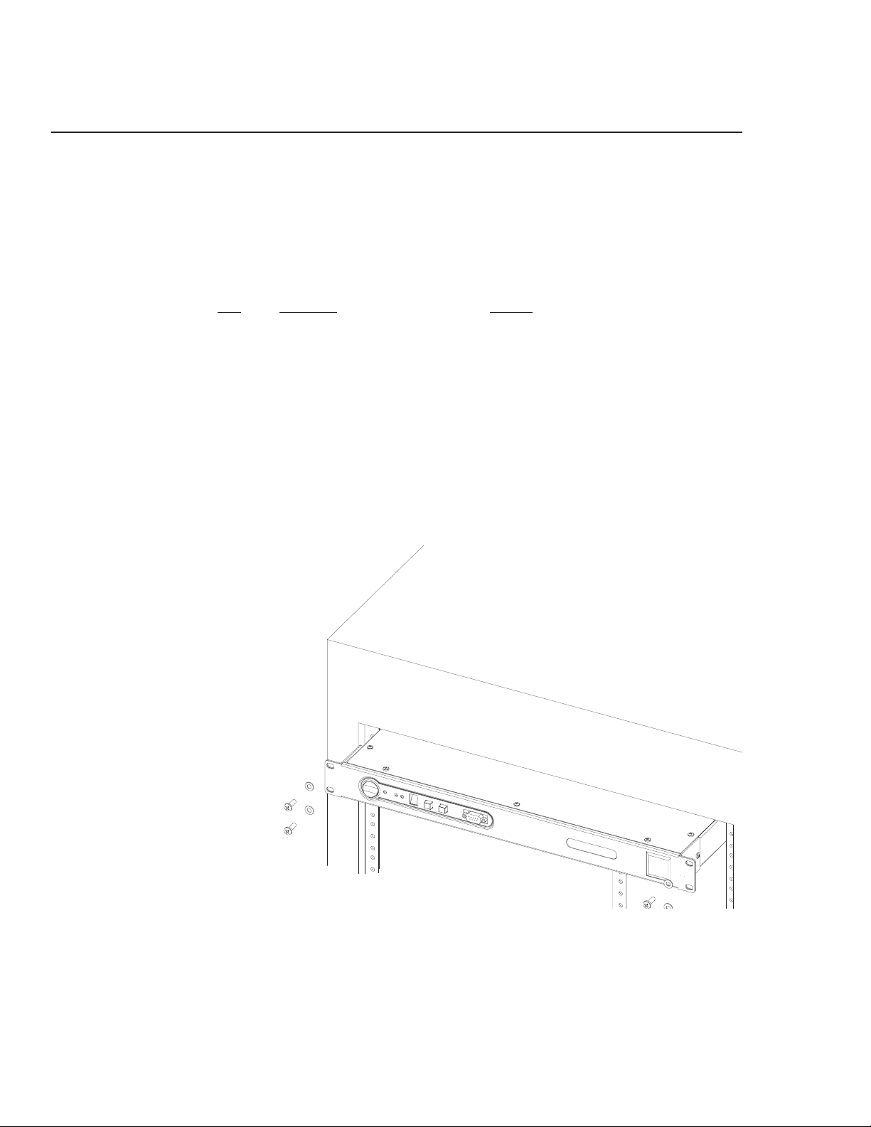
Mounting
The DSP-30 can be used in or out of an equipment rack. Adhesive rubber feet are included for non-rack mount installations.
Use them to prevent the unit from scratching or marring support surfaces.
Rack Mounting
Rack mount the DSP-30 by support-
ing it from underneath while align-
ing the mounting holes with the
threaded screw holes in the rails;
install all four mounting screws and
washers and tighten securely. Ensure
use of all four mounting screws in
order to minimize the chance of
bending or distorting the rack mount
ears. Rack mounting is optional.
Support the Rear for Portable/Mobile Installations
If the DSP-30 is to be transported while in a rack, we recommend supporting the rear of the chassis. This will help
prevent the unit from being damaged from the increased mechanical stresses of portable and mobile use. The DSP-
30’s chassis includes integral rear mounting tabs for securing to the rack mounting ears.
6
Page 7
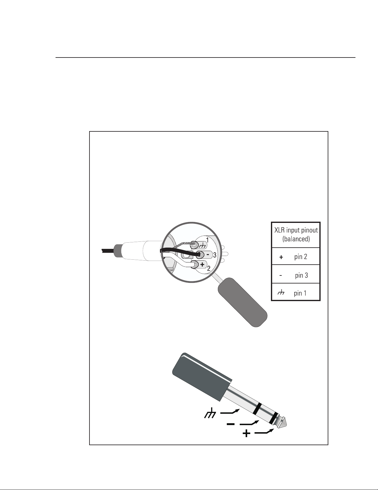
Installation: Balanced Audio Connections
Connecting Audio Inputs and Outputs
All audio connections should be balanced to ensure the best performance. Unbalanced signals may be used if necessary; follow
the wiring guidelines below for recommended unbalanced termination.
The audio input jacks are female 3-pin XLR /TRS “combo” connectors. They will accept male XLR plugs or TRS (tip-ring-sleeve)
1/4-inch phone plugs. The audio output jacks are male 3-pin XLR connectors.
BALANCED
Balanced connection is recommended for all inputs.
The XLR - TRS “combo” inputs are electronically balanced.
Balanced input cables are recommended to minimize noise
pick up and prevent ground loops.
Refer to the pinouts provided (below) for proper connection.
XLR
TRS (1/4 inch)
TRS- tip, ring, sleeve (3
conductors)
Suitable only for inputs.
7
Page 8
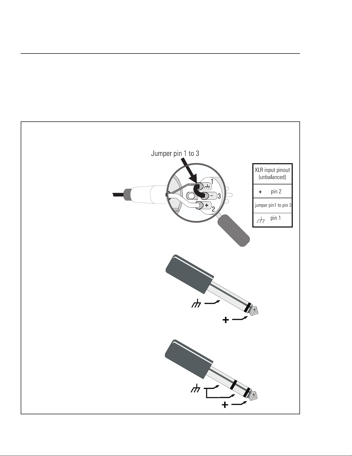
Installation: Unbalanced Audio Connections
Connecting Audio Inputs and Outputs
All audio connections should be balanced to ensure the best performance. Unbalanced signals may be used if necessary; follow
the wiring guidelines below for recommended unbalanced termination.
The audio input jacks are female 3-pin XLR /TRS “combo” connectors. They will accept male XLR plugs or TRS (tip-ring-sleeve)
1/4-inch phone plugs. The audio output jacks are male 3-pin XLR connectors.
UNBALANCED
Unbalanced inputs can be
used if required. If unbal-
anced audio sources are used,
it is preferable to use an ap-
propriate audio transformer (or
other unbalanced-to-balanced
“converter”) to provide a bal-
anced input. If this is not pos-
sible, then it is recommended
that the negative terminal and
shield terminal be connected
to one another with a jumper
wire.
XLR
TS (1/4-inch phone)
This style of plug
automatically connects
the negative terminal to
shield when inserted in
the jack.
TRS (1/4-inch)
NOTE for above abbreviations: TRS- tip, ring, sleeve (3 conductors)
TS- tip, sleeve (2 conductors)
8
Page 9
Installation: Connecting Audio Inputs and Outputs
Audio Connections
Once the input and output cables have been properly wired, they can be connected to the receptacles on the rear panel of the DSP-30.
INPUTS- Input jacks are “combo” style. They
accept either male XLR or 1/4-inch diameter TRS
phone plugs. Plug line level audio source into the
input jacks. Use balanced connections wherever
possible.
OUTPUTS- Output jacks are male XLR style. They
accept female XLR plugs. Connect the DSP outputs
to the next audio device in the signal chain (this is
usually a professional audio power amplifier). Use
balanced connections wherever possible.
Basic Audio Connections
Rear Panel Audio
Connections
The basic application shown is representa-
tive of most simple installations. The audio
source outputs (console output, media player)
are connected to the DSP’s input jacks. The
audio program material is processed by the
DSP and sent out the output jacks. Connect
the DSP’s outputs to the next device’s input
jacks. This next device is typically an audio
power amplifier, but can be other signal-
level devices, monitor busses, Ethernet au-
dio devices, etc...
As with all professional audio installations,
use balanced and fully shielded audio con-
nections wherever possible. If connection to
an unbalanced source is neccessary, use an
audio unbalanced-to-balanced converter (au-
dio transformer or active-DI box) to properly
isolate the source. If this is not possible, we
recommend that the unused minus ( - ) termi-
nal be connected to ground (the shield) in
order to minimize noise.
NOTE! AC line cord omitted for clarity. Ensure AC power is properly connected.
9
Page 10

Installation: Connecting to the RS-232 Port
Connecting to the RS-232 Port
Connect to the RS-232 port using the 9-pin serial data cable (included in the shipping box). Orient the DB-9 plug correctly,
insert the plug fully into the RS-232 port and finger-tighten the retaining screws. The cable length should be 25 feet or less.
“Null-modem” type cables will NOT work.
Connection to the computer is required only while loading the presets into the DSP-30 or for “real-time” adjustments to a
configuration before saving it as a Preset. Communication is established using the Signal Manager program. Refer to the
software help file section, “RS-232 Communication” for the proper procedure and software/hardware settings that effect
RS-232 communications.
DSP setup and programming takes place through the RS-232 port. Any time you need to load different presets, connect to
the computer using the RS-232 port. If “real-time” control is required, the RS-232 port connection is required. If you do not
need real-time control, then you can disconnect the serial port after loading the presets. The eight preset configurations
will remain in memory and can be recalled by using the front panel buttons as described on page 16.
RS-232 port connection
10
Page 11

Installation: System Requirements and Software Installation
The DSP-30 relies on the Signal Manager software for its DSP signal chains or configurations. You must use the supplied
software to design your configurations and then load those configurations into the DSP-30 using a simple RS-232
connection. The DSP-30, as shipped from the factory, is configured to pass audio signals from input to output unaffected
for all 8 presets. Use the software’s Help System for instructions on how to use the Signal Manager software.
System Requirements
To use the QSC Signal Manager software, you need the following:
• IBM compatible computer, 200 mHz or greater Pentium processor
• Windows 98/2000 or Windows NT 4.0 with Service Pack 6a or later
• SVGA display at 800 x 600 minimum resolution, 1024 x 768 recommended
• CD-ROM drive
• 32 MB or more of RAM
• 10 MB of free hard disk space
• An available RS-232 serial communications port (COM port) capable of 38.4k baud
• A male-to-female 9-pin serial cable (to connect the DSP to available COM port)
Software Installation
1. Insert the
start automatically after several seconds. If it does not, then proceed to step 2, below. Otherwise, skip to step 3.
2. Select Run from the Windows START menu. In the blank space, type “D:\setup.exe”. Press “OK”.
3. Follow the on-screen installation instructions.
4. After Signal Manager has finished installing, a “readme” file will automatically be displayed (by default). Please take the time to read
this important information. It contains the most recent information about using the software and related issues.
5. To run the application, double-click the QSC Signal Manager icon that was placed on your desktop during install or select “Programs,
QSC Signal Manager, Signal Manager” from the Start menu.
6. Refer to Signal Manager’s on-screen help system for detailed instructions on creating configurations and general use information. Also
visit QSC on the internet at http://www.qscaudio.com for DSP-related updates.
7. IMPORTANT! The DSP is shipped with all of its presets configured to pass full-range audio signals through both channels.
QSC Signal Manager
CD into your drive (typically drive “D:”). If your computer has AUTORUN enabled, the installation will
THIS MAY
NOT BE APPROPRIATE FOR YOUR SETUP! Be sure to configure any necessary crossovers , filters, etc. prior to applying audio
signals to the inputs. Damage to equipment may result if these recommendations are not followed.
• The last active Preset used when the unit is turned off becomes the active Preset again once the power is reapplied. This
ensures that the system “comes up” just as it was left last time it was powered down.
• Do not run your amplifier “wide open” (maximum gain) while making real-time adjustments to the DSP’s setup. The nature
of the communication path between the PC and DSP is inherently more complex than direct physical controls of an equivalent
analog processing device. Unpredictable results may occur due to failure of the PC or the communications channel. Under such
circumstances, damage to your drivers is possible if the amplifier gain is set for high power levels. Use the minimum useful gain
settings while making system adjustments.
11
Page 12
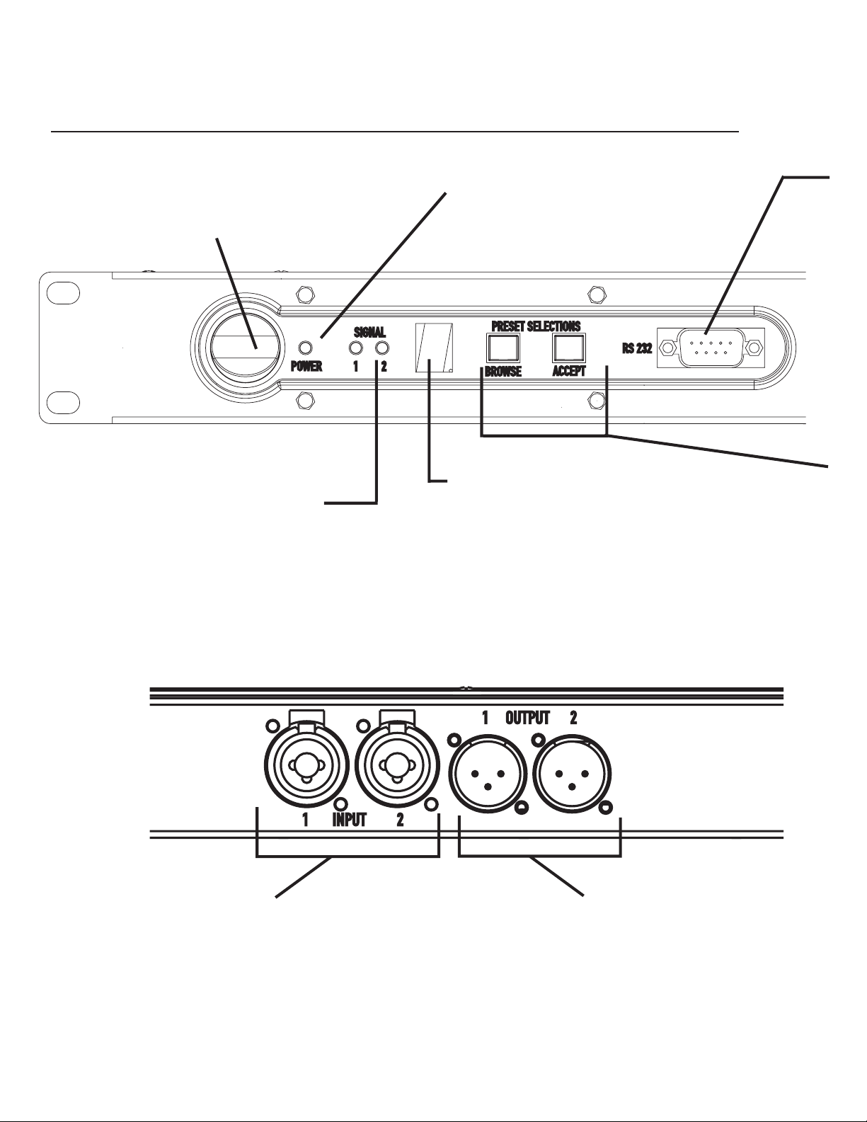
Use: Control, Indicator, and Connector Descriptions
FRONT PANEL
POWER switch- This rocker switch
turns the unit on by pressing the top
side of the switch. Turn off by pressing
the bottom side of the switch.
CHANNELS- These green LED’s illuminate when the unit detects an input
signal on each channel. Each channel’s
indicator operates independently. Dual
brightness levels indicate signal level.
At 40dB below clipping, they will light
dimly; at 20dB below clipping, they will
light brightly.
POWER indicator- This blue LED illuminates when the unit has power properly applied and the power switch is in
the “On” position.
NUMERIC DISPLAY- This multi-segment numeric display indicates the pre-
set selected. The decimal point after
the number indicates “lock” mode when
illuminated.
A steady display indicates the active
preset number. A flashing display indicates the pending preset selection.
REAR PANEL
CH 1 INPUT, CH 2 INPUT- These female XLR-combo
jacks are the line-level audio inputs to the unit. TRS or XLR
connectors may be used.
They are electronically balanced with an input impedance
of 8.3k Ohms. If used in an unbalanced configuration, the
input impedance is 3.7k Ohms.
Input sensitivity is selectable in software.
CH 1 OUTPUT, CH 2 OUTPUT-- These male XLR outputs
provide post-DSP (processed) signal from the unit. Connect the outputs to your amplifier’s inputs (or other
downstream device).
There is a software-selectable output pad that may be
used to attenuate the output level.
12
Page 13

Use: Control, Indicator, and Connector Descriptions
RS-232- This DB-9 female jack is for attaching the serial cable between the unit and
the computer. Use this connection for loading your DSP configurations from the
computer to the DSP and for “real-time” configuration tuning with
software.
Signal Manager
PRESET SELECTIONS buttons-
BROWSE- increments the Preset Memory and the Preset
Number Display.
ACCEPT- after using the BROWSE button to choose a
Preset number, press ACCEPT within 30 seconds to activate the selected Preset.
AC power receptacle-
The DSP-30 uses a detachable IEC standard power cord for connecting to a grounded AC
source. To connect power: identify the proper end of the cord, match the orientation of
the receptacle on the rear panel and insert firmly into the receptacle. The power supply
will accept from 100 to 240 Volts AC, 47 to 63 Hertz. Make sure the power cord used is
suitable for the line voltage the unit is connected to. If a different type of IEC power cord
is required, contact QSC’s Technical Services Department to obtain the correct one.
NOTE! Pressing the ACCEPT button and holding for at
least 3 seconds locks (disables) the BROWSE key to
prevent accidental operation. The ACCEPT key must be
pressed again and held for at least 3 seconds to
“unlock” the BROWSE button so that other presets may
be accessed again.
13
Page 14

Use: General Use Guidelines and Preset Description
IMPORTANT! Please read before operating this Digital Signal Processor with your audio system.
General Use Guidelines
This is a professional level DSP product that allows the user to
produce virtually unlimited signal processor variations and
configurations. Because of the infinite configuration possibili-
ties of digital signal processing, it is possible to create configu-
rations that may result in unwanted signals or uncontrollable
output.
The Signal Manager software has no way of knowing if the
DSP configuration you have designed will produce the results
you intend. You can create signal loops in a configuration that
may oscillate and damage your sound system if applied to the
unit. When applying an untested configuration or when
designing or experimenting with this unit, it is a very good idea
to turn down the amplifier’s physical gain controls. That way,
you won’t damage your speakers or create very loud sounds if
you apply a configuration that doesn’t do what you thought it
would.
As a general rule, DO NOT CREATE SIGNAL LOOPS! Do not mix
the output of a DSP object back into its own input! There is
nothing useful to achieve by doing this, you will only create an
oscillator that could damage your speakers. Also, USE THE
SINE AND NOISE GENERATOR OBJECTS WITH GREAT CAU-
TION! These functions produce signals that can harm your
speakers. Start with lowered gain settings. If you don’t hear
a signal when you think you should, DO NOT INCREASE THE
GAIN!!! If the signal isn’t audible at lower levels, there is
something else wrong. Turning up the gain to full exposes you
and your system to the possibility that some loose connection
somewhere will suddenly send a full-amplitude signal through
your sound system.
Like all freely configurable signal processing tools, this DSP
will do what the configuration your design tells it to do, which
may not be what you expect it to do, so use caution.
Factory Presets
14
NOTE! The factory setting for all eight presets is wire-through.
Signals are passed from input to output without any processing.
You may select configurations from the sample files (*.cfg)
within Signal Manager or create your own.
Page 15

Use: Saving Presets Using QSC’s Signal Manager software
Presets
The DSP-30 must be loaded with your desired presets using the Signal
Manager program before use. Test all new presets for expected behavior at
low power levels to avoid inadvertently damaging speaker systems.
The DSP-30 has eight Preset memories numbered 1 through 8. Presets are DSP configurations
saved to memory in the DSP. Only one preset may be active at one time. The possible configurations of
the presets are essentially limitless. You will need to configure the preset memories with signal
chains that meet the precise requirements of your sound system using QSC’s Signal Man-
ager software. For help creating configurations, refer to the software’s on-line Help system
for detailed information.
Configuring the DSP-30’s Presets
The DSP configurations created with the Signal Manager software are not usable until they are saved
into the DSP. The software includes a collection of various sample configurations for your use. Modify
and save them as your own configurations if they prove useful in your applications. You may also create
your own to precisely fit your audio system. Once a configuration has been created and saved, it may be
loaded into the DSP.
How to Save Presets into the DSP-30
1- Connect the DSP-30 to the PC using a 9-pin serial cable. Run the Signal Manager program.
The preset configuration that is running in the DSP will be displayed on the Signal Manager
workspace. It should match the front panel LED display of the DSP-30.
2- You may now create a new configuration (or modify the existing one) to be saved as a DSP
preset. To create a new configuration, select
clear the workspace and activate the DSP tools and filter icons. If a configuration already
exists in the computer, choose the
figuration from the
Open
the bottom of the workspace changes from reading ‘ACTIVE’ to ‘EDIT.’
3- After creating (or editing) your configuration and making the necessary parameter changes,
Configuration/Save DSP Preset
select
tion Number that you wish to program. Press the OK button.
4- Once the DSP is programmed with the configuration, the text banner at the top of the
workspace will reflect the selected Preset Identification Number, as should the front panel
LED of the DSP-30.
NOTE! When programming presets into the DSP-30, be sure
that the preset selected is the one you wish to overwrite.
Once the configuration is applied to the DSP-30, the selected
preset’s previous information is overwritten.
Configuration/New
Configuration/Open
menu item and select the desired con-
from the menu bar. This will
window. Note that in each of these cases, the Configuration Pane at
from the menu bar. Then choose the Preset Identifica-
15
Page 16

Use: How to Recall a Preset from the Front Panel
TO RECALL A PRESET-
1- Press the
The selection display flashes until Step 2 (below) is completed.
2- Press the
Once the preset is active, the display will stop flashing.
Additional Tips:
BROWSE
ACCEPT
Note! The
selecting the preset. If a longer time passes, the DSP-30 will
revert to its original preset.
a) Recalling presets will typically be done without the use of a PC by using the Browse and Accept buttons on the front panel.
However, a PC with Signal Manager software may be used if desired. Refer to the on-line Help file to learn more about this.
b) Each preset can be dramatically different from one another. For that reason, when a preset is changed the outputs will
mute, the DSP will be reconfigured, and then the outputs will unmute. This happens in fractions of a second. This ensures
that undesired transients are minimized during preset changes. For live shows, this limits the changing of presets to pauses
in the program material (like in between songs or sets).
key until the desired preset number shows in the display.
key to activate the selected preset in the DSP.
ACCEPT
button must be pushed within 30 seconds of
c) The front panel buttons can be ‘locked’ to prevent undesired operation. The next page describes how to do this.
FRONT PANEL DISPLAY- Indications during preset operation and recall
Example- Preset 1 is active
as indicated by the steady
illumination of the display.
Press BROWSE once and
the display will increment
to “2.” The display will
flash, indicating the
ACCEPT button must be
pushed to confirm the
selection.
Press ACCEPT once and
the display will change
from flashing to steady
illumination. The ACCEPT
button must be pushed
within 30 seconds of
preset selection.
16
Page 17

Use: LOCK OUT Feature
TO LOCK THE FRONT PANEL BUTTONS (Browse and Accept pushbuttons)-
Press the Accept button and hold it down for at least three seconds.
1-
2- The “lock” indicator will illuminate.
3- The Browse button is disabled.
Press the Accept button and hold
for three seconds to lock/unlock the
preset selection.
FRONT PANEL DISPLAY-
Example shows Preset 7 in
“unlocked” and “locked” state.
TO UNLOCK FRONT PANEL BUTTONS-
Press and hold the Accept button for at least three seconds.
1-
2- The Lock indicator will extinguish.
3- The Browse button is enabled.
UNLOCKED
LOCKED
LOCK INDICATOR
illuminated when
locked
Note: When the PC is communicating with the DSP-30, the LOCK INDICATOR will occasionally illuminate.
This is normal and prevents commands from both the front panel and PC from interfering with one another.
17
Page 18

Use: Contact Closure Feature
Contact Closure Feature
The contact closure feature is used to trigger gain changes
in the DSP. Any configuration that uses one or more
switched gain objects (see Signal Manager software Help
file ) can take advantage of this feature. The contact
closure will trigger all switched gain objects at once.
Wiring Diagram for Contact Closure
This feature requires the construction of a simple RS-232 cable (or through-adapter plug) that brings
out pins 5 (GND) and 9 (contact closure trigger). These pins may be connected to a simple toggle or
pushbutton switch that will be used to trigger a switched gain object in a DSP configuration. Refer to
Signal Manager software Help file for available contact closure features.
All switched gain objects in a DSP configu-
ration will be triggered by the one contact
closure. It is not possible to trigger
switched gain objects individually!
18
Page 19

Use: RS-232 Pinout
RS-232 Pinout:
The diagram below shows the pin assignments for the female RS-232 connector on the DSP.
Pin Signal Description
1 DCD
2 TD
3 RD
4 DTR
5 GND
6 DSR
7 RTS
8 CTS
9 Contact Closure
*Note! Pin 9 is used for contact closure input. This pin is not normally used by RS232 devices. Some laptop and desktop computer COM ports have been observed to
“pull” pin 9 to ground; this will cause unexpected behavior of the contact closure
function if pin 9 is not disconnected on the PC end of the cable. If this behavior is
observed, make sure that pin 9 is disconnected on the PC end of the cable.
19
Page 20

Use: Application Example
TRI-AMPED PA CABINETS WITH SUBWOOFER (refer to illustration at right)
This is highly generalized, but shows the main idea in cre-
ating larger systems. In this example, the audio source
material is connected to the inputs of all four DSP’s. Take
care to keep right and left channel signals connected to the
correct channels of downstream equipment. For example,
keep all left channel signals routed through the channel 1
sections of downstream gear and all right channel signals
routed through channel 2 sections of downstream gear. This
preserves stereo imaging.
Each DSP would be setup independently with the appropri-
ate crossover response and equalization for the specific
driver being used. Refer to the speaker’s (or driver’s) docu-
mentation for recommended frequency range, drive level,
and any other applicable information. In the example at right,
DSP #1 (assigned to high frequency drivers) might be set up
for a high pass filter with a -3dB point of 6 kHz and high-
speed limiters to protect them from transients. DSP #2 (as-
signed to midrange drivers) might be set for a band pass
filter, with -3 dB points at 1 kHz and 7 kHz using mild signal
limiting. DSP #3 (assigned to low frequency drivers) might
provide a 45 Hz to 1100 Hz bandpass with EQ to remove
modal resonances of the listening environment. DSP #4
(subwoofer drive) could be assigned a low pass filter with a
-3dB point of 50 Hz and equalization as required. All the
filters mentioned above would have assignable response
type (where applicable) and assignable slope characteris-
tics enabling precise tuning of the system.
Power requirements for high frequency drivers are gener-
ally much lower than for low frequency drivers; this requires
either reduced gain in the signal processing stage or the
lower power amplifier for the high frequency drivers. The
opposite is true for the subwoofers; they generally require
the highest power to drive them, so assign your most pow-
erful amplifiers to the lowest frequency drivers. Assign your
amplifiers to the drivers according to the required power
levels .
20
Page 21

Use: Application Example
TRI-AMPED PA CABINETS WITH SUBWOOFER: Sample Application Diagram
21
Page 22

Specifications
Audio Converters 24 bit, 48 kHz.
Frequency response 20 Hz–20 kHz ±0.4 dB
at 1dB below full
scale input voltage (all sensitivities)
Distortion <0.007% THD+N @ 1dB below full scale output, all sensitivities, 20 Hz– 20 kHz
Group Delay 1.00 milliseconds
Dynamic range >95dB unweighted, 1.5V, 4V and 9V input sensitivity
AES-17 -60dB method >93dB unweighted, 18V input sensitivity
Polarity In-phase or inverted
Mute >95 dB attenuation
Indicators Power: 1 blue LED Channel 1 and Channel 2 signal presence: 2 green LED’s
Preset Display: 7 segment LED
Inputs
Program inputs 2
Connector 3-pin female XLR -TRS 1/4” combo jack
Type Electronically balanced
Grounding All shield terminals connect to chassis
Input sensitivity Level and units are selectable
(full scale input level) in software interface
Impedance 8.3 K Ohm balanced
3.7 K Ohm unbalanced
Common-mode rejection >54 dB, 20 Hz–20 kHz
Crosstalk >80 dB separation, 20 Hz–20 kHz
Input/Output Termination: All XLR’s: pin 2- hot (+), pin 3- cold ( - ), pin 1- ground / All 1/4” TRS: tip- hot, ring- cold, sleeve-ground
Outputs
Program outputs 2
Connector 3-pin male XLR receptacle
Type Electronically balanced
Grounding All shield terminals connected to
chassis
Output level Level and units are selectable
(full scale) in software interface
Maximum Output 9.3 Vrms (+21.5 dBu)
Output Pad -6dB
Output impedance 600 Ohms balanced
RS-232 Port
Port Description RS-232, female, straight through
Cable Type supplied: 9-pin serial cable, male-to-female (serial extension cable)
Maximum Cable Length 25 feet (7.6 meters)
Contact Closure Input (sense)
Inputs 1 discrete input, TTL compatible, pin #9 of RS-232 port
Configuration Single-ended input, pull LOW (to GND, pin 5) for closure detect
Resistance for closure detect <150 Ohms
Resistance for open detect >1.9 K Ohms
Maximum Voltage +9 VDC
22
Note: Specifications are subject to change without notice.
Page 23

Specifications
Signal Processing Capabilities
Compressor (RMS responding) 8 programmable presets
Peak limiter
(peak responding)
Parametric equalization Signal splitter
High and Low shelf Filter
High and Low pass Filter
Delay
(910 millisecond max., all delay objects, 20.83 microsecond increments)
Signal level meter
Signal gain/attenuation
Mixer
(2 to 1 mixer with
(responses: Butterworth, Bessel, Linkwitz-Riley)
(peak or RMS responding)
(with mute or bypass)
mute
and
Pink and white noise generator
Variable frequency tone (sinewave) generator
Contact closure input
(pin 9 of the RS-232 port can be pulled to ground (pin 5) for control purposes)
Gain Structure (balanced input and output)
tupnI
ytivitisneS
gnitteS
.V05.1tuOV56.1
.V00.4tuOV93.4
.V00.9tuOV09.9
.V00.81tuOV05.71
daPtuptuO
gnitteS
V(leveL
lock channels
langiStupnI
lluF,
smr
)tupnielacs
smr
smr
smr
smr
RS-232 control
Signal polarity selection
feature)
tuptuO
egatloV
V03.9
smr
V03.9
smr
V03.9
smr
V02.6
smr
tnatluseR
niaG
Bd0.51+
Bd5.6+
Bd5.0+
Bd0.9-
.V05.1nIV56.1
.V00.4nIV93.4
.V00.9nIV09.9
.V00.81nIV05.71
smr
smr
smr
smr
General
Physical
Chassis Type Steel (chassis & covers)
Height 1.73 inches
Width 18.9 inches (including rack ears)
Depth 14.9 inches (including rear ears)
13.7 inches (excluding rear ears)
Weight 9.5 lb. (4.3 kg) net
12.5 lb. (5.7 kg) shipping
Mounting Stand-alone or rack mount
Operating temperature 0° to 50° Celsius
V07.4
smr
V07.4
smr
V07.4
smr
V01.3
smr
Bd0.9+
Bd5.0+
Bd5.6-
NOTE! Full scale output voltage of
the DSP-30 is 9.30 Volts (rms)
Bd0.51-
Internal Power Supply
AC Input Voltage 100–240 VAC, autodetect
AC Input Current 0.3 Amps (rms) at 120 VAC
Frequency 40 to 63 Hz
Power Cord
Recommended IEC-type 3-conductor, #18 AWG
Note: Specifications are subject to change without notice.
23
Page 24

Architect’s and Engineer’s Specification
The Digital Signal Processor (DSP) shall provide two independent
channels of DSP for signal delivery to all professional power
amplifiers. Input and output sensitivity shall be adjustable to
accommodate consumer and pro audio signal levels.
Output Peak Limiter—For each audio channel, the DSP shall
provide a peak limiter that is assignable anywhere in the
signal chain and can be bypassed. Its operation shall be
based upon the peak signal level. The limiter shall provide
the following adjustments:
Gain
Threshold
Attack time
Release time
Predictive Delay
High- and Low-Pass Filters—For each channel of audio, the
DSP will provide high-pass and low-pass filters that are
assignable anywhere in the audio chain. The DSP shall
provide the following crossover responses:
Butterworth (6,12,18,24 dB per octave slope)
Bessel (6,12,18,24 dB per octave slope)
Linkwitz-Riley (12 & 24 dB per octave slope)
High- and Low-Pass Shelf Filters—For each audio channel, the
DSP shall provide high-pass and low-pass shelf filters
that are assignable anywhere in the audio chain. The
shelf filters must be capable of being bypassed. The DSP
shall provide the following shelf filter adjustments:
Variable corner frequency
Compressor-- The DSP shall provide a signal compressor that is
assignable anywhere in the signal chain. It shall be based
upon the RMS signal level. The compressor shall be
capable of being bypassed. The compressor shall provide
the following adjustments:
Gain
Threshold
Attack time
Release time
Compression ratio
Predictive Delay
Power Supply—The DSP shall be provided power from an inter-
nal power supply that operates from line voltages in the
range of 100-240 VAC and frequencies from 40 to 63
Hertz. Line cord connection to the DSP shall be via an IEC-
type line cord receptacle.
Amplifier Interface—The DSP shall connect to amplifiers using
standard 3-pin XLR connections. Provisions for both bal-
anced and unbalanced connection shall be provided.
Noise & Tone Generation-- The DSP shall provide pink and
white noise generation capability. It shall also provide for
user-specified tone generation. Level control of noise
and tone objects shall be provided
Presets— The DSP shall be capable of storing eight preset
configurations. Preset recall capability shall be via two
front panel push-button switches and shall not require
the use of a computer. The control software shall provide
management of these presets.
Variable gain
Variable slope
Contact Closure I/O—The DSP shall provide a trigger input
usable for contact-closure (or other) purpose which shall
be CMOS & TTL signal compatible.
24
General—All audio inputs and outputs shall be balanced. Audio
input and output sensitivity shall be programmable using
the control software. Units will be user-selectable from
dBu, dBV and Volts (rms).
Control— The DSP shall be configurable via a front panel acces-
sible RS-232 port.
The Digital Signal Processor shall be the QSC DSP-30.
Page 25

Maintenance, Warranty & QSC Contact Information
Cleaning
The faceplate and chassis can be cleaned with a soft cloth and
nonabrasive, mild cleaning solution. Products like Simple Green
and Windex work well. Do not use powders or scrubbing pads of any
type as they are usually abrasive and will permanently damage the
finish of your DSP-30. Dampen a soft, lint-free cloth with the
cleaning solution and wipe the unit down gently. Insure that
cleaning solution does not get into the connectors. Do not spray the
solution directly onto the unit as it will penetrate into the connec-
tors.
User Maintenance
There are no user servicable parts in the DSP-30. Contact QSC’s
Technical Services Department if service is required.
Warranty Information
If the DSP-30 isn’t working properly, please verify that a known
good 9-pin serial cable is used between the DSP-30 and the
computer for loading Presets. If proper operation can not be
restored, the DSP-30 may require service. This must be per-
formed by qualified service personnel. To obtain the location of
your nearest QSC Authorized Service Center, please contact your
QSC dealer or contact QSC’s Technical Services Department.
Disclaimer
QSC Audio Products, Inc. is not liable for any damage to speakers,
amplifiers, or any other equipment that is caused by negligence or
improper installation and/or use of this digital signal processor.
QSC Audio Products, Inc. is not liable for any direct or indirect
damage caused by computer communications failure.
Product Warranty
QSC guarantees the DSP-30 to be free from defective material and/
or workmanship for a period of three years from the date of sale, and
will replace defective parts and repair malfunctioning products
under this warranty when the defect occurs under normal installa-
tion and use—provided the unit is returned to our factory via
prepaid transportation with a copy of the proof of purchase, such as
a sales receipt. This warranty provides that examination of the
returned product must indicate, in our judgment, a manufacturing
defect. This warranty does not extend to any product which has
been subjected to misuse, neglect, accident, improper installation,
or where the serial number and date code have been removed or
defaced.
If the DSP-30 is returned to the factory for service, it should be sent
in the proper QSC carton. If you did not save the original carton, ask
your QSC dealer for one or call QSC to have one sent to you. This
warranty does not cover shipping damage caused by improper
packing or the use of improper shipping cartons.
WORLD WIDE WEB:
http://www.qscaudio.com
TELEPHONE NUMBERS:
Main Number (714) 754-6175
Sales Direct Line (714) 957-7100
or (800) 854-4079 toll free (U.S.A. only)
Technical Services (714) 957-7150
or (800) 772-2834 toll free (U.S.A. only)
FACSIMILE (FAX) NUMBERS:
Sales & Marketing FAX (714) 754-6174
Technical Services FAX (714) 754-6173
ADDRESS:
QSC Audio Products, Inc.
1675 MacArthur Boulevard
Costa Mesa, CA 92626-1468 USA
25
Page 26

Notes27Notes
26
Page 27

Page 28

28
1675 MacArthur Boulevard Costa Mesa, California 92626 USA PH: (714) 754-6175 FAX: (714) 754-6174
© Copyright 2001, QSC Audio Products, Inc.
QSC® is a registered trademark of QSC Audio Products, Inc., Costa Mesa, CA
“QSC” and the QSC logo are registered with the U.S. Patent and Trademark Office
 Loading...