

Page 1
Music & Paging Zone Mixer
®
User Manual
MP-M80 Firmware Version 1.1
MP-M40 Firmware Version 1.1
TD-001578-01-B
*TD-001578-01*
Page 2
EXPLANATION OF TERMS AND SYMBOLS
The term “WARNING!” indicates instructions regarding personal safety. If the instructions are not followed the result may be bodily injury or death.
The term “CAUTION!” indicates instructions regarding possible damage to physical equipment. If these instructions are not followed, it may result in
damage to the equipment that may not be covered under the warranty.
The term “IMPORTANT!” indicates instructions or information that are vital to the successful completion of theprocedure.
The term "NOTE" is used to indicate additional useful information.
The intent of the lightning flash with arrowhead symbol in a triangle is to alert the user to the presence of un-insulated "dangerous"
voltage within the product's enclosure that may be of sufficient magnitude to constitute a risk of electric shock to humans.
The intent of the exclamation point within an equilateral triangle is to alert the user to the presence of important safety, and operating
and maintenance instructions in this manual.
IMPORTANT SAFETY INSTRUCTIONS
1. Read these instructions.
2. Keep these instructions.
3. Heed all warnings.
4. Follow all instructions.
5. Do not use this apparatus near water.
6. Do not submerge the apparatus in water or liquids.
7. Do not use any aerosol spray, cleaner, disinfectant or fumigant on, near or into the apparatus.
8. Clean only with a dry cloth.
9. Do not block any ventilation opening. Install in accordance with the manufacturer's instructions.
10. Keep all ventilation openings free of dust or other matter.
11. Do not install near any heat sources such as radiators, heat registers, stoves, or other apparatus (including amplifiers) that produce heat.
12. To reduce the risk of electrical shock, the power cord shall be connected to a mains socket outlet with a protective earthing connection.
13. Do not defeat the safety purpose of the polarized or grounding-type plug. A polarized plug has two blades with one wider than the other. A
grounding type plug has two blades and a third grounding prong. The wide blade or the third prong are provided for your safety. If the provided
plug does not fit into your outlet, consult an electrician for replacement of the obsolete outlet.
14. Protect the power cord from being walked on or pinched particularly at plugs, convenience receptacles, and the point where they exit from
theapparatus.
15. Do not unplug the unit by pulling on the cord, use the plug.
16. Only use attachments/accessories specified by the manufacturer.
17. Unplug this apparatus during lightning storms or when unused for long periods of time.
18. Refer all servicing to qualified service personnel. Servicing is required when the apparatus has been damaged in any way, such as power-supply
cord or plug is damaged, liquid has been spilled or objects have fallen into the apparatus, the apparatus has been exposed to rain or moisture,
does not operate normally, or has been dropped.
19. The appliance coupler, or the AC Mains plug, is the AC mains disconnect device and shall remain readily accessible after installation.
20. Adhere to all applicable, local codes.
21. Consult a licensed, professional engineer when any doubt or questions arise regarding a physical equipment installation.
22. Inspect the apparatus, including the power supply for signs of external wear and tear or signs of damage. All damage to the apparatus should
be immediately repaired by a QSC authorized service station or QSC International Distributor. Failure to perform necessary repairs could lead
to additional damage or to safety hazards. Failure to perform necessary repairs voids the limited warranty and QSC is not responsible for any
injury, harm or related damages arising from any failure to perform those repairs.
Maintenance and Repair
WARNING!:
maintenance and repair methods. To avoid a danger of subsequent damage to the apparatus, injuries to persons and/or the creation
of additional safety hazards, all maintenance or repair work on the apparatus should be performed only by a QSC authorized service
station or an authorized QSC International Distributor. QSC is not responsible for any injury, harm or related damages arising from any
failure of the customer, owner or user of the apparatus to facilitate those repairs.
TD-001578-01-B
Advance technology, e.g., the use of modern materials and powerful electronics, requires specially adapted
ii
Page 3

FCC Statement
NOTE:
FCCRules.
These limits are designed to provide reasonable protection against harmful interference in a residential installation. This equipment generates, uses
and can radiate radio frequency energy and, if not installed and used in accordance with the instructions, may cause harmful interference to radio
communications. However, there is no guarantee that interference will not occur in a particular installation. If this equipment does cause harmful
interference to radio or television reception, which can be determined by turning the equipment off and on, the user is encouraged to try to correct
the interference by one or more of the following measures:
• Reorient or relocate the receiving antenna.
• Increase the separation between the equipment and receiver.
• Connect the equipment into an outlet on a circuit different from that to which the receiver is connected.
• Consult the dealer or an experienced radio/TV technician for help.
This equipment has been tested and found to comply with the limits for a Class B digital device, pursuant to Part 15 of the
Warranty
For a copy of the QSC Limited Warranty, visit the QSC website at www.qsc.com
Para una copia de la Garantía Limitada de QSC, visite el sitio web de QSC, en www.qsc.com
Pour obtenir une copie de la garantie limitée de QSC, visitez le site de QSC à www.qsc.com
Besuchen Sie die Webseite von QSC (www.qsc.com) um eine Kopie der beschräenkte Garantie von QSC zu erhalten.
如果您想要QSC有限保修的複印本,请造访QSC品的网站www.qsc.com
Для ознакомления с условиями ограниченной гарантии, посетите страницу компании QSC в интернете www.qsc.com
www.qsc.comQSCQSC
TD-001578-01-B
iii
Page 4

Table of Contents
Maintenance and Repair ........................................................................ii
FCC Statement ...............................................................................iii
RoHS STATEMENT ............................................................................. iii
Warranty ..................................................................................... iv
Music & Paging Zone Mixer Reference ....................................8
Getting Started ............................................................................... 8
System Requirements .............................................................................................8
MP Install .........................................................................................................8
MP Manage .......................................................................................................8
MP-MFC Controllers ..............................................................................................8
MP-M Hardware .......................................................9
Front Panel ................................................................................... 9
Rear Panel .................................................................................... 9
Specifications ....................................................................................................10
MP Install ............................................................11
Control Panel .................................................................................11
Input Channels ............................................................................... 12
Input Channel − Block Diagrams ...................................................................................12
Mic/Line and Auto-Mixer ................................................................................................12
Line, USB, Music on Hold, Cue, Wireless Paging ...........................................................................12
Input Channels – Home Screen ...................................................................................13
Input Channel – Navigation & Master Controls .....................................................................14
Input Channel – Setup ............................................................................................15
Input Channel – Overview .........................................................................................16
Input Channel – Presets ..........................................................................................17
Factory Presets ........................................................................................................17
User Presets ...........................................................................................................18
Input Channel – PEQ ..............................................................................................19
Input Channel – Dynamics ....................................................................................... 20
Compressor ........................................................................................................... 20
Automatic Gain Control (AGC) ...........................................................................................21
Input Channel – Gate ............................................................................................ 22
Input Channel – USB Player Setup ...............................................................................23
Input Channel – USB Player Overview ............................................................................ 24
Input Channel – USB Player ...................................................................................... 25
Input Channel – USB Player PEQ ................................................................................. 26
Input Channel – USB Dynamics Automatic Gain Control (AGC) ..................................................... 27
TD-001578-01-B
iv
Page 5

Output Zones ................................................................................ 28
Output Zone – Block Diagrams ................................................................................... 28
Mono Zone ............................................................................................................ 28
Stereo (Linked) Zone ................................................................................................... 28
Output Zone – Home Screen ..................................................................................... 29
Output Zone – Navigation & Master Controls ..................................................................... 30
Output Zone – Setup / Delay ......................................................................................31
Output Zone – Music on Hold .................................................................................... 32
Output Zone – Overview ......................................................................................... 33
Output Zone – Sources .......................................................................................... 34
Output Zone – Presets ......................................................................................... 35
Factory Loudspeaker Library ........................................................................................... 35
User Presets .......................................................................................................... 36
Filters & PEQ .......................................................................................................... 37
Output Zone – Graphic Equalizer (GEQ) ........................................................................... 38
Output Zone – Anti-Feedback .................................................................................... 39
Output Zone – Loudness ......................................................................................... 40
Output Zone – Limiter ............................................................................................41
Mixer ....................................................................................... 42
Mixer Main – Block Diagram ..................................................................................... 42
Mixer Main – Home Screen ...................................................................................... 42
Mixer Main – PEQ ............................................................................................... 43
Mixer – FX Channel ...........................................................................44
Mixer – FX Effect ............................................................................................... 44
Mixer – FX Presets ..............................................................................................44
Mixer – FX Shelf EQ ............................................................................................. 45
Setup Wizard ................................................................................46
Menu ....................................................................................... 47
Menu – Home Screen ........................................................................................... 47
Menu – Configurations .......................................................................................... 48
Managing Configurations - Online ....................................................................................... 48
Managing Configurations – Offline ....................................................................................... 49
Configuration Files and Windows ........................................................................................ 49
Common Workflow Scenarios ...........................................................................................49
Menu – Scenes ..................................................................................................51
Menu – Scheduling .............................................................................................. 52
Menu – Controllers ............................................................................................. 53
Menu – Smartphone ............................................................................................ 54
Menu – GPI Setup ............................................................................................... 55
Menu – Report .................................................................................................. 56
TD-001578-01-B
v
Page 6

Menu – System Test ............................................................................................ 57
Menu – Network ................................................................................................ 58
USB Wi-Fi Adapters ................................................................................................... 58
Network Help Button ................................................................................................... 58
Connecting to a Facility’s Network ...................................................................................... 58
Menu – Wired Network Setup: Auto IP Address ......................................................................... 59
Menu – Wired Network Setup: Static IP Address ........................................................................ 60
Menu – Wireless Network Setup: Create New Network ...................................................................61
Menu – Wireless Network Setup: Connect to Existing Network ........................................................... 62
Menu – Security ................................................................................................ 63
Staff Access Management .............................................................................................. 63
Reset Passwords ...................................................................................................... 63
Menu – Settings ................................................................................................ 64
Multi-Function Controller ............................................. 65
Setup (
Operation ................................................................................... 65
Refer to Menu – Controllers.) ......................................................................................65
MP Manage ......................................................... 66
MP Manage – Security ........................................................................ 66
Log in as Manager ............................................................................................... 66
Add a New User ................................................................................................. 66
MP Manage – Home Screen .................................................................... 67
MP Manage – Zone Overview .................................................................. 68
MP Manage – Zone Edit ....................................................................... 68
MP Manage – Scheduler ......................................................................69
To Modify an Event (New or Existing) ............................................................................. 69
MP Manage – Scenes ......................................................................... 70
MP Manage – Player .......................................................................... 70
MP Manage – Mixer ...........................................................................71
MP Manage – Paging ......................................................................... 72
MP-M Dimensions ....................................................61
MP-M Block Diagrams ................................................ 64
Mic/Line Input Channels & Auto Mixer ..........................................................64
Line Inputs, USB Inputs, Music on Hold, Cue, Wireless Paging .....................................65
Mono Zone Output ...........................................................................66
Stereo (Linked) Zone Outputs ................................................................. 67
Mixer ....................................................................................... 68
TD-001578-01-B
vi
Page 7
Music & Paging Zone Mixer Reference
The information provided in this section gives you a detailed description of the screens and controls for the Music & Paging Zone Mixer and the
Music & Paging Zone Mixer remote apps.
Getting Started
The QSC MP-M music and paging mixers are fixed architecture mixer/processors offering unprecedented capabilities combined with ease of
configuration and operation. The products are intended for retail and hospitality applications in which high-quality audio from various sources
is routed to multiple zones. Live mixing functions are also supported for applications requiring reinforcement of entertainment, presentations or
conferences.
System Requirements
The MP-M Apps support:
• Android – 5.0 or later
• iOS – 8.0 or later
• macOS – 10.9 or later
• Windows – 10
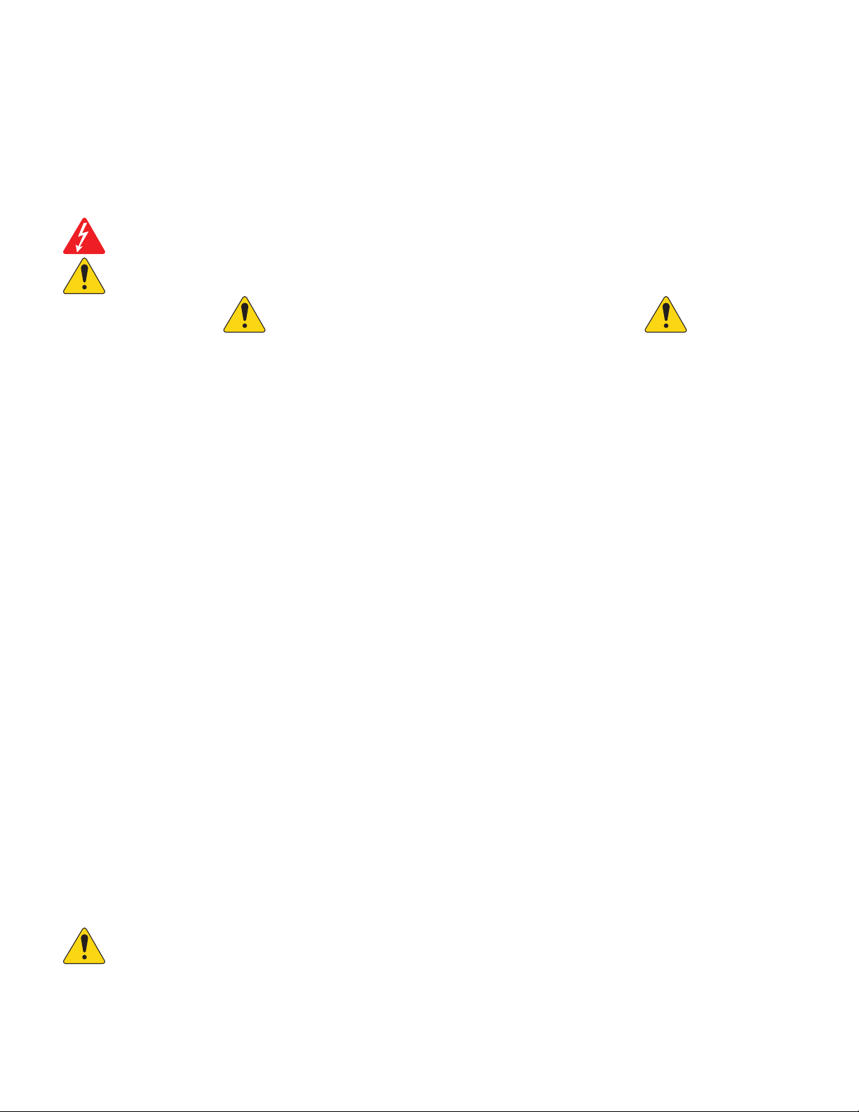
MP Install
This app (for iOS / Android tablets, Windows and Mac OS) allows system designers and installers to
quickly and easily design and configure systems for MP-M Series mixers. This wireless control features
an intuitive Workflow Wizard to navigate through room tuning and speed commissioning.
MP Manage
For wireless control, the MP Manage app (for iOS / Android tablets and smartphones) provides end users day-today operation of basic system functions including zone level, source selection, scene recall, scheduling, and mixer
control. It also offer a unique store-and-forward zone paging functionality to the MP-M Series mixer.
MP-MFC Controllers
The MP-MFC Controllers are intuitive wall mount controls to enable customizable system adjustments for the MP-M Series
music and paging mixer. They provide multi-zone source selection, scene selection and volume control. Designers can
configure these peripherals to provide end users with as much or as little control over the system as needed.
TD-001578-01-B
1
Page 8
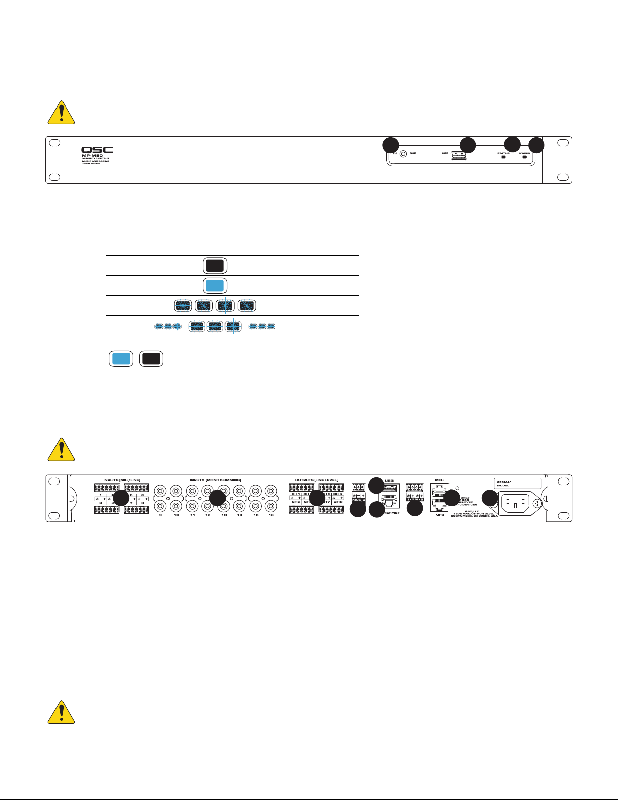
Rear Panel
1.
2.
3.
4.
5.
6.
7.
8.
9.
MP-M Hardware
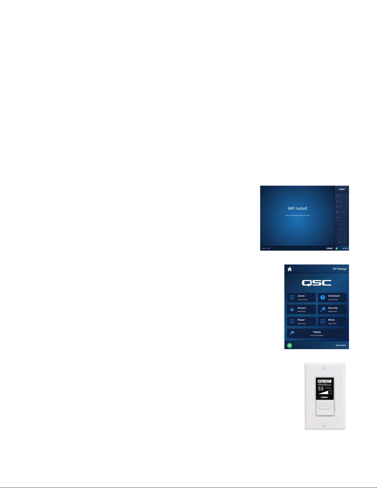
Front Panel
NOTE:
1.
2.
3.
4.
3
MP-M80 is shown.
CUE
– Headphones, 3.5 mm, stereo
USB
– USB-A (rear panel – 1, front panel – 1), fi rmware & confi guration uploads, USB Wi-Fi
STATUS
POWER
–
Action Appearance Defi nition
Off OK
On Booting
Slow Blink Firmware Upgrade
SOS Blink Upgrade Failure
–
On Off
1
2
4
NOTE:
MP-M80 is shown.
INPUTS (MIC/LINE)
connectors
INPUTS (MONO SUMMING)
OUTPUTS (LINE LEVEL)
Euroblockconnectors
MUSIC ON HOLD
USB
Ethernet
GPI
MFC
AC Mains
TD-001578-01-B
– USB-A (rear panel – 1, front panel – 1), fi rmware & confi guration uploads, USB Wi-Fi
– 2 Inputs, Euroblock
– MP-MFC ports, up to 4 MFC’s per connection, 2 RJ45 connectors
1 9
– Mic / Line Inputs, balanced, 12 V Phantom power, MP-M80 has 8 inputs, MP-M40 has 4 inputs, 6-pin Euroblock
– Transformer-balanced, 3-pin Euroblock connector
– RJ45 For connecting to a network, wired and/or wireless.
– power connection, 100-240 V, ~85 W, 50/60 Hz
CAUTION!:
If AC power is removed, wait for 5 seconds before reapplying the AC power.
5
2
– RCA Pairs, summed to mono, MP-M80 has 8 pairs, MP-M40 has 4 pairs
– Balanced, Line Level, MP-M80 has 8 line level outputs, MP-M40 has 4 line level outputs, 6-pin
3
4
6
7
8
2
Page 9

Specifications
Model MP-M40 MP-M80
Inputs
Total 8 16
Mic/Line 4 (Euroblock) 8 (Euroblock)
RCA 4 (mono-summed RCA pairs) 8 (mono-summed RCA pairs)
Outputs
Total 6 10
Line 4 (Euroblock, balanced) 8 (Euroblock, balanced)
Music-on-Hold 1 (Euroblock, transformer balanced) 1 (Euroblock, transformer balanced)
Cue (phones) 1 (3.5 mm, stereo) 1 (3.5 mm, stereo)
Audio
Sampling frequency 48 kHz
Processing 32-bit floating point
THD <0.005%, +4 dBu and -2 dBr; 20 Hz-20 kHz, unity gain, any input to any output
Frequency response 20 Hz-20 kHz +/-0.5 dB, mic/line or line input to any line output
Dynamic range >106 dB unweighted
Crosstalk >90 dB typical, >80 dB max
Gain (mic inputs) 51 dB
Maximum input level +24 dBu (mic/line inputs), +10dBV (line inputs)
Maximum output level +21 dBu (line-level outputs), +10dBV (Music on Hold)
Phantom power All microphone inputs (+12 volts)
Latency 2.3 msec
Input Processing
EQ 4-band parametric EQ with high/low shelving option, variable 24 dB/octave HPF and LPF
Dynamics Gate, choice of Auto Gain Control (AGC) or compressor
Output Processing
EQ 1/3 octave GEQ
Anti-feedback filters 12-band variable notch filters
Dynamics Comp/limiter, ducker, loudness
Delay 100 msec
Loudspeaker tunings
Control Accessories
MP-MFC Optional wall controller
MP Install For configuration/design functions (for iOS/Android tablets, Windows and Mac OS PCs),
MP Manage For end user control functions (for iOS/Android tablets and smartphones)
Other Connections
Ethernet 1 x RJ45 for connection to Wi-Fi router (user supplied)
MP-MFC ports 2 x RJ45
USB 2 USB-A (firmware & configuration uploads, USB Wi-Fi)
GPI 2 inputs (Euroblock)
Power requirements 100-240VAC, 50-60 Hz, universal supply, IEC inlet
Indicators
Dimensions (Net)
Weight
Shipping 11.0 lb (5.0 kg)
Net 7.0 lb (3.2 kg)
Specifications are subject to change without notice.
Factory: Intrinsic Correction™ voicing for QSC loudspeakers
User: 6-band parametric EQ, HPF & LPF (Linkwitz-Riley or Butterworth; 12, 18 or 24 dB/octave)
Blue POWER LED, blue STATUS LED
1.75 in x 19 in x 14 in (4.5 cm X 48.3 cm X 35.6 cm)
TD-001578-01-B
3
Page 10
MP Install
MP Install is an app that runs on iOS, Android and Windows. It is intended for use by system designers and installers. See the Network section of
this document for instructions on logging in to a new MP-M for the fi rst time.
Control Panel
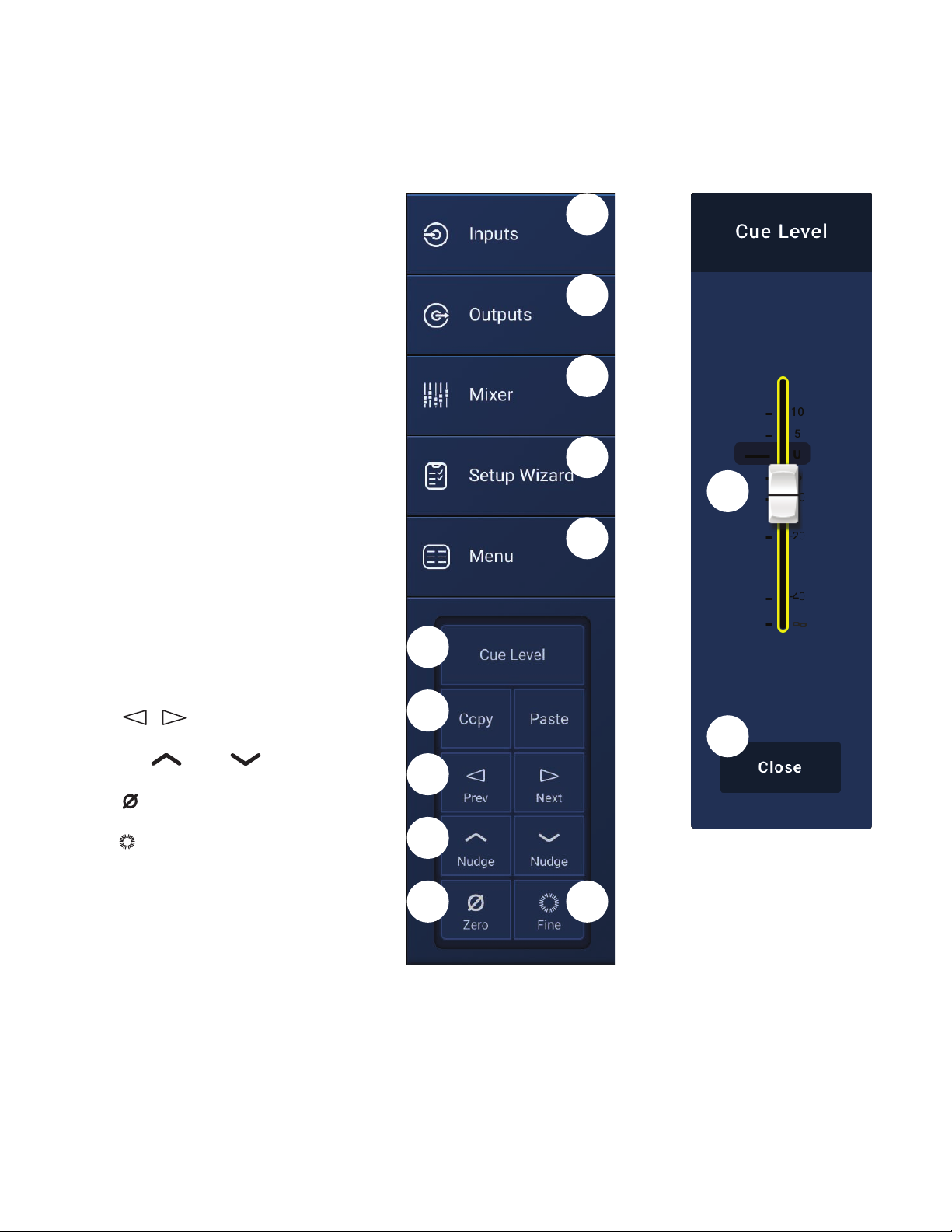
The Control Panel (right side of screen) provides navigation
to all mixer controls, indicators and functions.
Navigational Controls
1.
2.
3.
4.
5.
Operational Controls
6.
7.
8.
9.
10.
11.
12.
13.
1
Inputs
– Opens a screen that displays icons
representing the controls and processing blocks for
input channels.
Outputs
representing the controls and processing blocks for
output channels.
Mixer
Setup Wizard
checklist of setup tasks and links to areas of the mixer
where the tasks are performed.
Menu
functions for the system.
Cue Level
Copy
but simple copy and paste function. Copy and Paste is
context sensitive so what you are looking at is what will
be copied. Only “like” things can be copied and pasted
from and to each other. For example, a PEQ cannot
be pasted to a GEQ. Some screens cannot be copied,
for example the Inputs Home screen. In these cases a
dialog displays saying “Copy not available here”.
Prev
or previous channel.
Nudge
decreases the value setting of the selected control.
Zero
factory default value.
Fine
that will be applied by the Nudge buttons.
Cue Level
audio from the Cue output jack.
Cue Level
pop-up.
– Opens a screen that displays the icons
– Opens the MP-M built-in mixer screen.
– Opens a screen that provides a
– Opens a screen providing access to the setup
and
&
button – Returns the selected control to its
button – Decreases the amount of change
button – Opens the Cue Level pop-up.
Paste
buttons – The MP-M has a powerful
Next
buttons – Navigate to the next
up & down buttons – Increases or
fader – Touch and drag to adjust the level of
Close
button – Touch to close the Cue fader
6
7
8
9
10
2
3
4
12
5
13
11
TD-001578-01-B
4
Page 11
Input Channels
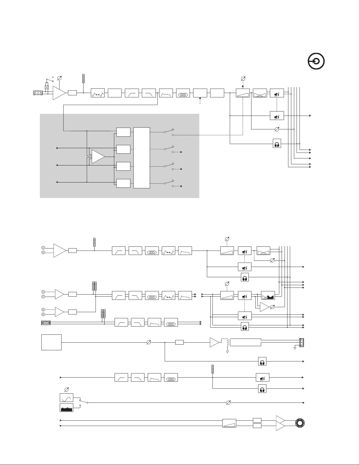
Input Channels Block Diagrams
Mic/Line Input Channels and Auto-Mixer
MP-M40: 1 of 4 Mic/Line Inputs / MP-M80: 1 of 8 Mic/Line Inputs
Line Inputs, USB Inputs, Music on Hold, Cue, Wireless Paging
MP-M40: 1 of 4 Mic/Line Inputs / MP-M80: 1 of 8 Mic/Line Inputs
+12 V
To Outputs
To Outputs
Wireless Paging
To Outputs
Mixer
From
From
From
From
Mic Pre
Gain
A/D
Delay
Polarity
Φ
Automatic Microphone Mixer
Compare
Compare
Compare
Compare
MP-M40: 4 Channels
MP-M80: 8 Channels
Low Cut
Auto-Mixer
Algorithm
Mic/Line
Input 1
Mic/Line
Input 1
Mic/Line
Input 2
Mic/Line
Input 3
Mic/Line
Input 4
To
Mic/Line
Ch. 2
To
Mic/Line
Ch. 3
To
Mic/Line
Ch. 4
Store &
Forward
From GPI
or Gate
AGC
High Cut PEQ Comp
Gate
Gain
Gain
Level
Pan
Mute
Mute
FX
Cue
Mixer
L R
FX
Touch Inputs
Cue
L R
To Cue
To FX
To Mixer
Line
Input 1
Line
Input 1 & 2
Linked
USB Input
Music On Hold
MOH Source
Selection
From Inputs
From
Wi-Fi
Signal
Generator
From
Cue
Sum
Sine
Noise
A/D
A/D
A/D
Frequency
Low Cut
High Cut PEQ
Low Cut
High Cut PEQ Dynamics
Low Cut High Cut PEQAGC
Level
Low Cut High Cut PEQAGC
Delay
Delay
Dynamics
DAC
Level
Gain
Gain
Level
Gain
Gain
Noise Level
Cue
Gain
Gain
Mute
Mute
Cue
Mute
Mute
Cue
DAC
DAC
Pan
Balance
Cue
Mute
Cue
FX
FX
Line inputs only
L R
L R
FX
Cue
To Mixer
To FX
To
Linked
Outputs
To Cue
Music
On
Hold
To Cue
To Cue
To
Outputs
Phones
TD-001578-01-B
5
Page 12
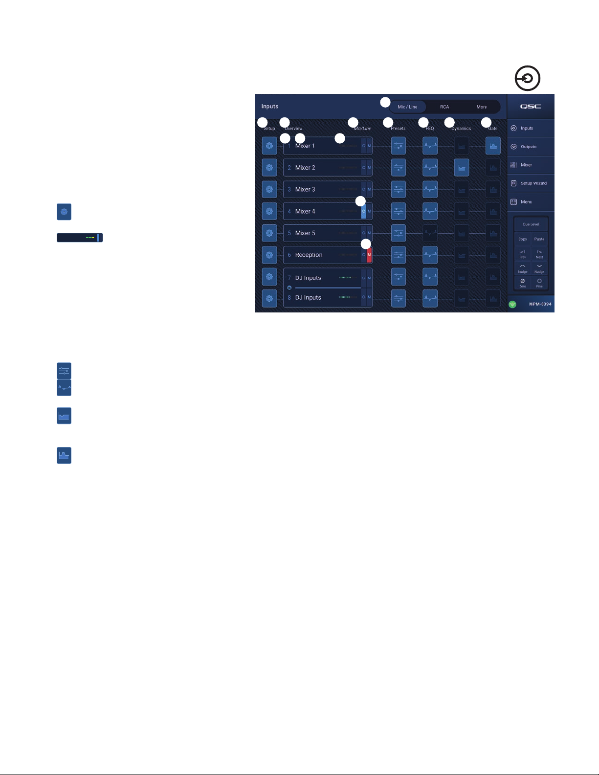
Input Channels – Home Screen
The Inputs home screen displays a high-level overview
of the channels in a channel bank along with links to the
various control groups, Setup, PEQ, Dynamics, and so on.
1.
2.
3.
4.
5.
6.
– Dark button indicates the PEQ is not engaged, light button indicates the PEQ is engaged. Touch the button to access the PEQ screen
7.
button indicates the Dynamics are engaged. Touch the button to access the Dynamics screen where switching between the AGC or Compressor,
8.
Touch Inputs
Channel Banks (MP-M80 Shown) – Select
fromchannels
•
Mic/Line
– Displays Mic/Line input
processingblocks.
•
RCA
– Displays processing blocks for the mono-
summed RCA inputs.
•
More
– Displays processing blocks for the USB
Player and Wi-Fi paging.
Setup
– Touch to access Input Name, Channel
Safe, Stereo Link, Reset and Delay.
C
ManagersMic
1
screen. The Inputs screen displays:
a. Channel number
b. Name
c. Level meter
C
d.
M
Overview
– Touch to access Overview
– Cue status light color indicates the Cue is
active, dark color indicates the Cue is inactive.
e. M – Mute status Red indicates the channel is
muted, dark color indicates channel is not muted.
Type of Input – Mic/Line or Mono Summed
Presets
PEQ
where all PEQ parameters and engaging / disengaging the PEQ can be accessed.
Dynamics
– Touch to access the Presets screen to access recall, reset, save / save as, Factory and User presets, and more.
– The Dynamics consists of a Compressor and an AGC. A dark button indicates the Compressor / AGC is not engaged, light
and modifying all parameters and engaging / disengaging the Dynamics can be accomplished.
Gate
– Dark button indicates the Gate is not engaged, light button indicates the Gate is engaged. Touch the button to access the Gate
screen where you can modify all Gate parameters and engage / disengage the Gate.
1
3
2
3a 3b
4
3c
5
3d
3e
7
6
8
TD-001578-01-B
6
Page 13
Input Channel − Navigation
and Master Controls
Input channels are the audio source for all Output Zones
and for the MP-M Internal Mixer. All controls on the input
channels affect the Mixer and the Output Zones with the
exception of the Fader, Pan and Auto-Mix which affect only
the Mixer. When an Input Channel is selected the following
controls and indicators are available
Input Channel Navigation Controls
The icons at the top of the screen are used to navigate the
channel processing blocks. Refer to the individual topics
for details of the following:
1.
2.
3.
4.
5.
6.
7.
Input Channel Master Controls
8.
9.
10.
11.
12.
13.
14.
15.
16.
17.
18.
Mic/Line
Setup
– The Setup screen provides controls to
change the channel name, input trim, and various
otherfunctions.
Overview
– The Overview screen displays and
provides controls for most of the parameters
associated with a channel.
Presets
– The Presets screen provides controls to
recall, save, and manage presets.
PEQ
– The Parametric EQ screen provides controls to
adjust the parametric EQ for the channel.
Dynamics
– The Dynamics screen provides the option to select the Compressor or AGC (Automatic Gain Control), and the controls to adjust
either.
Gate
– The Gate screen provides controls to setup and make adjustments to the Gate.
Prev / Next
– Navigates to the next or previous channel. The buttons cycle through the Input, Line In, and FX channel, then loops back to
Input1.
Inputs
1
3
2
4
5
Touch an
Input Bank
(RCA / More)
6
11
12
13
Touch a Channel
7
8
9
16
10
14
15
17
18
Setup Button
Channel
Cue
Channel Type and Number
G
C
P
Meter
Mute
Fader
Pan
Auto-Mix
label – Displays the name as entered in the Setup screen’s Input Name fi eld.
– Sends the pre-fader channel signal to the Cue headphone output.
– Indicates that the Gate for the channel is engaged or not.
– Indicates that the Dynamic processing (Compressor or AGC) for the channel in engaged or not.
– Indicates that Phantom power for the channel is engaged or not.
– Indicates the channel signal level. This meter is Pre-fader.
– Mutes the channel going to the zones and to the MP-M internal mixer.
NOTE:
The MP-M includes an internal mixer. The following controls adjust the channel’s signal in the mixer only and have no effect
on the channel signal that is sent to the zones.
– Adjusts the level of the channel’s signal in the MP-M internal mixer.
– Adjusts the Left/Right balance of the channel in the MP-M internal mixer.
(microphone inputs only) – Applies the Auto-Mixer (see the Mixer Section topic) to the channel.
– Displays the type of channel (Mic, Stereo, Playback, Record, FX) and its number. This cannot be changed.
TD-001578-01-B
7
Page 14
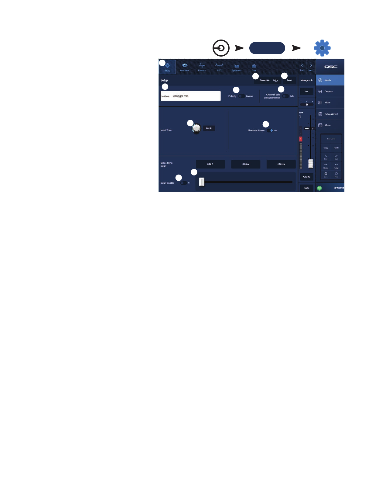
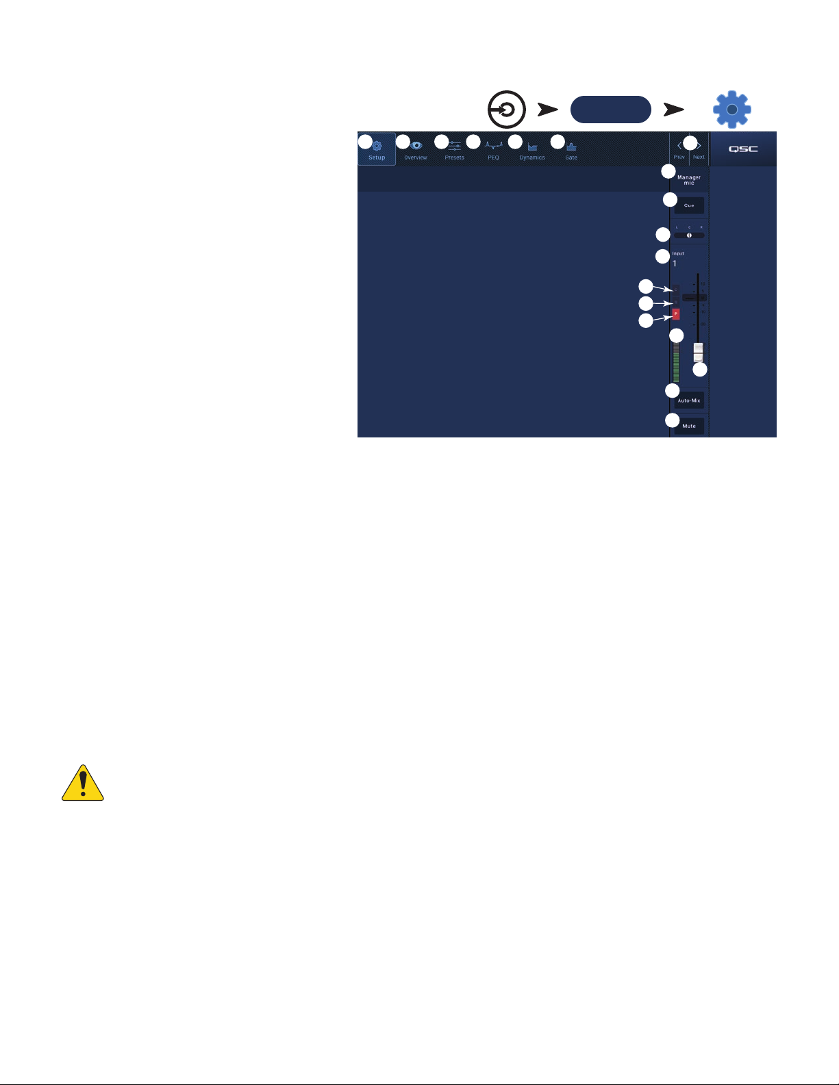
Input Channel − Setup
The setup screen includes a number of functions that are
primarily “set once and forget”. Channel Setup is provided
for all input channels.
1.
Setup
2.
3.
4.
5.
6.
7.
8.
9.
slider – Video Sync Delay allows the audio to be delayed by up to 100 milliseconds. The delay value is also displayed in feet
and meters. This feature is typically used to compensate for “lip fl ap” which occurs when the latency of a video signal is greater than that of the
10.
Delay Enable
switch – Engages or disengages the Video Sync Delay.
Touch an
Touch a Channel
Mic/Line
button – Selects the Setup screen.
Stereo Link
button – Links / unlinks adjacent
channels for stereo operation. The odd numbered
channel settings are copied to the even numbered
channel. Pan settings are mirrored. Only odd/even
linking is supported (1-2, 3-4, etc.). Even/odd linking
(2-3, 4-5) is not available.
Reset
button – Returns all Setup settings, for this
channel, to default values.
Input Name
fi eld – Displays the name of the channel.
Touch to display a keyboard and rename the channel
with a “friendly name”. Use only upper and lower case
alpha characters.
Polarity
switch – Inverts the polarity of the
inputsignal.
Channel Safe During Scene Recall
switch – When
set to Safe, the channel will not be affected by a
scenerecall.
Input Trim
knob – Adjusts the input sensitivity for the
Mic/Line channels. Not available on the USB Player or Wifi Paging.
Phantom Power
switch – Turns phantom power on or off for the channel (Mic/Line input channels only). (available on MP-M80 channels1-8
and on MP-M40 channels 1-4)
Video Sync Delay
accompanying audio.
Inputs
1
4
7
9
10
5
Input Bank
(RCA / More)
2
8
Setup Button
3
6
TD-001578-01-B
8
Page 15
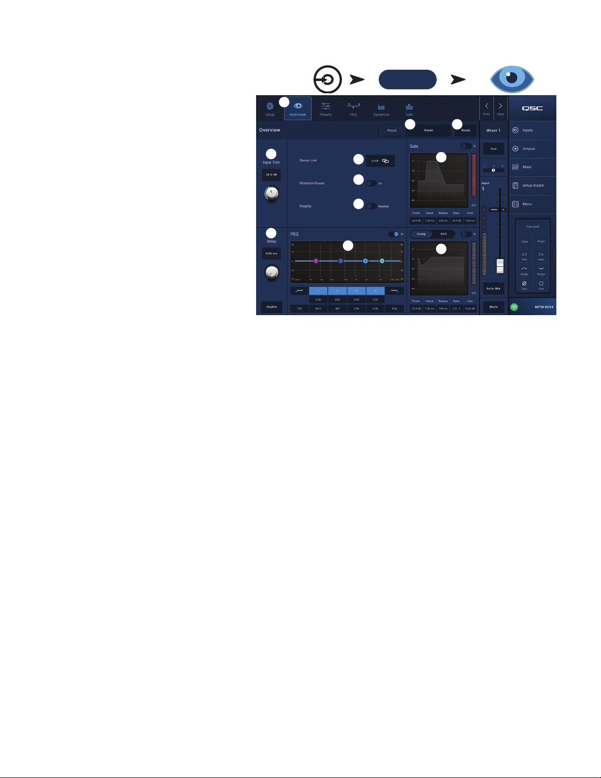
Input Channel − Overview
The Input Overview screen displays an at-a-glance view
of the settings for the selected input. Most controls on this
screen also appear on other input screens.
To copy all the settings for an input, touch the Copy button
while this screen is displayed. To paste the settings to
another input, navigate to the target input and touch Paste.
The following items are available on the Input Channel
Overview screen.
1.
2.
3.
4.
5.
6.
7.
8.
9.
10.
11.
Available controls for the AGC on this screen are: In, Max Target, Min Target, Max Gain, Threshold, and Release. Select a control and use the
Nudge buttons to change values. (See topic for details.)
Touch
Mic/Line
Inputs
Touch an
Input Bank
(RCA / More)
Touch a Channel
Overview Button
Navigation
icons – Touch an icon to navigate to the
associated Input Channel processing block. (See topics
for details.)
Preset
button – Displays the currently active input
preset. Touch the fi eld to navigate to the Presets
processing block to recall or manage presets. This fi eld
is not available on the USB Player or WiFi channels.
(See topic for details.)
Reset
button – Touch to reset all Input Channel
controls to the factory default setting.
Input Trim
Mic/Line channels. Not available on the USB Player or
Wifi Paging.
Stereo Link
Phantom Power
and on MP-M40 channels 1-4)
Polarity
Gate
to change values. Not available on the USB Player or WiFi channels. (See topic for details.)
Delay
PEQ
(See topic for details.)
Comp
knob – Adjusts the input sensitivity for the
button – Links adjacent, odd/even channels for stereo operation. Not available on the USB Player or WiFi channels.
switch – Turns phantom power on or off for the channel (Mic/Line input channels only). (available on MP-M80 channels1-8
switch – Reverses the polarity for the channel signal. Available on Mic/Line input channels only.
– Available controls on this screen are: In, Threshold, Attack, Release, Attenuation, and Hold. Select a control and use the Nudge buttons
knob and
Enable
button – Adjusts delay and enables / disables the delay. Not available on the USB Player or WiFi channels.
– Available controls on this screen are: In, HPF, LPF, Gain, and Frequency. Select a control and use the Nudge buttons to change values.
and
AGC
–
a. Available controls for the Compressor on this screen are: In, Thresh, Attack, Release, Ratio, and Gain. Select a control and use the Nudge
buttons to change values. (See topic for details.)
b.
1
2
4
9
5
6
7
10
3
8
11
TD-001578-01-B
9
Page 16
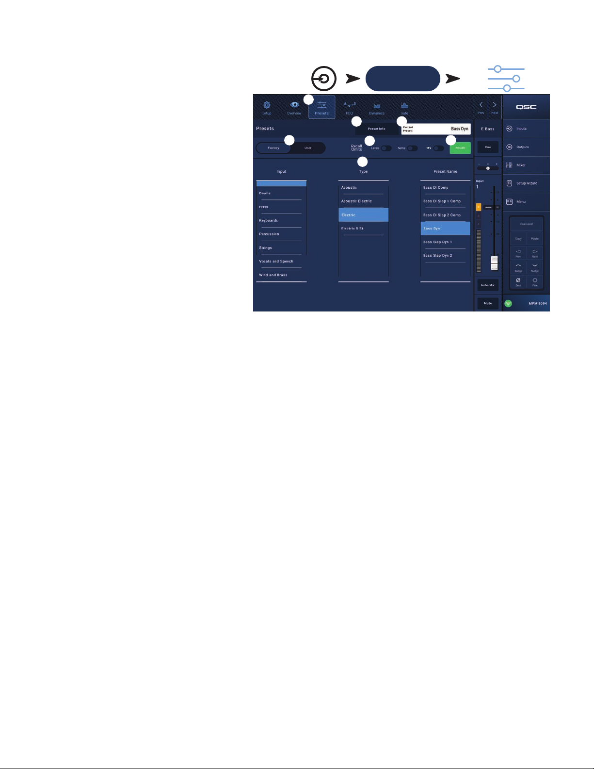
Input Channel − Presets
The MP-M includes presets for speech and musical
instruments. The musical instrument presets are intended
for applications in which the Mixer section is used for
reinforcement of live entertainment.
An Input Channel Preset consists of settings for the
channel EQ, dynamics and gate that can be saved and
recalled. The channel name and level settings are also
stored with the preset but may be omitted from a preset
recall by setting the Recall Omits switches to omit them.
Factory Presets
1.
2.
3.
4.
5.
6.
7.
Inputs Touch an Input Bank
1
Mic/Line
(RCA / More)
Touch a Channel
Presets Button
4
Presets
Preset Info
button – Displays the Presets screen.
button – Touch to displays a pop-up
message with details about the current Preset. Touch
OK on the pop-up to close.
Current Preset
fi eld – Displays the name of the
currently active preset.
Factory / User switch
– For this topic, set the
switch to Factory. Selects between the internal factory
presets or user presets. Refer to the User Presets topic
for details.
Recall Omits
– Allows selected parameters to be
unaffected by a preset recall. The parameters that can be selected are:
the switch is “on”.
Recall
button – Touch to recall the preset selected in the Selection windows.
Selection windows
– These windows (
Input, Type
, and
Preset Name
2
5
7
Levels, Name, 12V
3
phantom power. The parameter is selected when
) are used to select a preset for recall.
6
12 V
TD-001578-01-B
10
Page 17
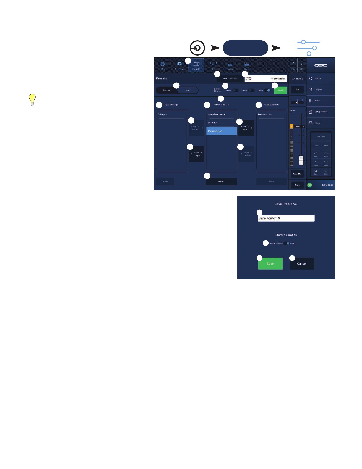
User Presets
The User Preset screen is where custom user tunings and
presets are stored and managed.
1.
Presets
2.
3.
4.
5.
6.
7.
8.
selected, the Copy to MP-M button will copy the preset to MP-M internal memory. You cannot Recall a preset from App Storage. To Recall, save
9.
10.
One item in the App Storage list, MP-M Internal list, or the USB External list must be selected for the following controls to be available.
11.
12.
13.
14.
15.
1
Save / Save as
button – Displays the Presets screen.
button – Touch to display a pop-up
message with details about the current Preset. Touch
OK on the pop-up to close.
TIP:
If a Factory Preset is recalled, it
can then be saved as a user preset. This
can be used as a start on which to build
custompresets.
Save Preset As
a.
keyboard and enter a different name for the preset
fi eld – touch the fi eld to access a
or, leave the name as it is, and continue to the
nextstep.
b.
Storage Location
switch – Select either
MP-M Internal (on the mixer), or USB attached to
themixer.
c. Save button – Touch the button to save the preset
in the selected location.
d. Cancel button – Touch the button to exit the dialog
without saving the preset.
Current Preset
Factory / User switch
fi eld – Displays the name of the currently active preset.
– Selects between the internal factory presets or user presets. User
presets may be stored and recalled to and from the MP-M internal memory or an attached
USB storage device.
Recall Omits
– Allows selected parameters to be unaffected by a preset recall. The
parameters that can be selected are: Levels, Name, 12V Phantom power. The parameter is
selected when the switch is “on”.
Recall
button – Touch to recall the preset selected in either the MP-M Internal, or the USB
External list.
Selection windows
– These windows (App Storage, MP-M Internal, and USB External) are
used to select a preset for recall and to copy presets from one location to another.
App Storage
list - Displays any user presets stored in the internal memory of the device being used to control the MP-M. When this panel is
Inputs Touch an Input Bank
Mic/Line
(RCA / More)
Touch a Channel
Presets Button
2
4
8
13
9
11
15
5
7
3
6
10
12
14
1a
1b
1c 1d
the preset to MP-M Internal, then Recall.
MP-M Internal
list – Displays any user presets stored in the MP-M internal memory. When this panel is selected, the selected Preset can be
copied to either the App Storage or USB External. In addition, the Preset can be recalled, then be saved or saved as a different preset.
USB External
copied to the MP-M Internal storage. In addition, the Preset can be recalled, then can be saved or saved as a different preset.
list – Displays any user presets stored on a connected USB device. When this panel is selected, the selected Preset can be
Copy To MP-M
Copy to USB
Copy To App
Copy to MP-M
Delete
button – Deletes the selected preset.
button – Touch to copy a selected preset from the App Storage to the MP-M Internal storage.
button – Touch to copy a selected preset from the MP-M Internal storage to the USB storage.
button– Touch to copy a selected preset from the MP-M Internal storage to the App Storage.
button– Touch to copy a selected preset from the USB External storage to the MP-M Internal storage.
TD-001578-01-B
11
Page 18
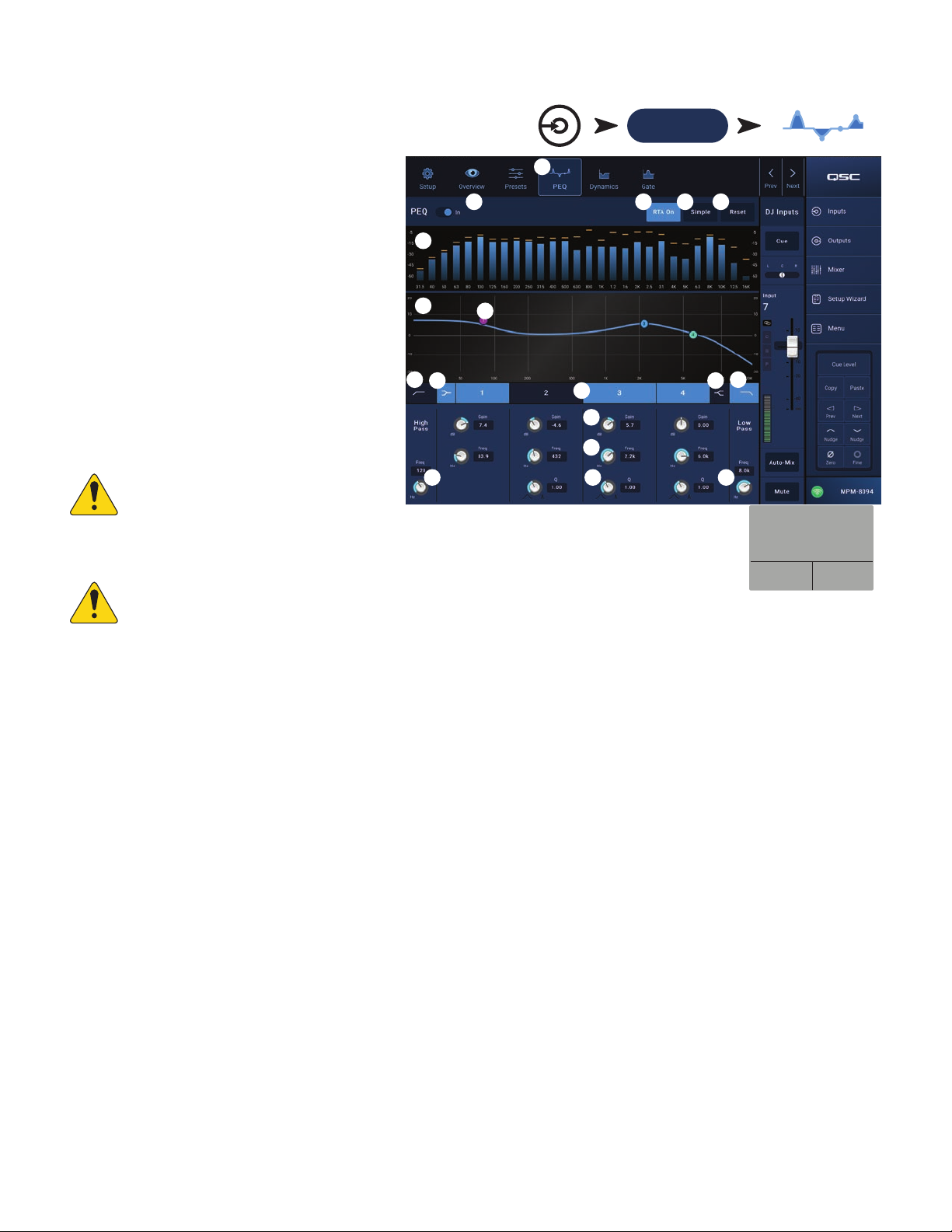
Input Channel − PEQ
This screen controls and displays the settings for the
Input Channel parametric equalization.
The PEQ is a 4-band, fully parametric EQ that includes
variable HPF (High Pass Filter) & LPF (Low Pass Filter).
1.
2.
3.
4.
5.
6.
7.
8.
9.
10.
engaged, the Q control is not available. The low shelving fi lter raises or lowers a range of frequencies below the set frequency. The high shelving
11.
12.
13.
14.
15.
Touch an
Touch a Channel
• The HPF is variable with a range of 20 Hz
to 2,000 Hz. It passes frequencies above
the setting while cutting those below.
• The LPF is variable with a range of 1 kHz
to 20 kHz. It passes frequencies below the
setting while cutting those above.
• Bands 1 and 4 may be confi gured as
shelvingfi lters.
PEQ
tab – Selects the EQ screen.
PEQ Out/In
RTA On
– Engages / disengages the equalizer.
– Engages / disengages the a real time
analyzer that displays the tonal balance of the
channel’s signal including peak hold indicators.
NOTE:
Only one RTA may be running on
the system at a time. Touch the RTA
button. If another device is using the RTA,
the message to the right displays.
Inputs
2
6
7
9
10
15
8
1
11
12
13
14
Input Bank
Mic/Line
(RCA / More)
3 4
5
9
10
15
The RTA is currently being
used by [device name]. Do
you want to assign it in-
stead to this device?
PEQ Button
NOTE:
Simple
button – Hides the Frequency, and Q controls for all bands and low and high cut fi lters. Changing to Simple mode does not affect
When the RTA is off, the Parametric EQ graph expands to use the entire graph area.
existingsettings.
Reset
button – Sets all the PEQ controls to their factory default position.
RTA
display – Displays the amplitude of the channel signal in 1/3 octave bands. Peak hold indicators are displayed for each band.
•
RTA
graph vertical scale – Represents audio level from -60 dB to-5dB.
•
RTA
graph horizontal scale – Represents frequency from 31.5 Hz to 16 kHz.
Parametric EQ
graph – A graphic representation of the equalization curve based on the PEQsettings. The trace dims to indicate that the PEQ
is Out(disengaged).
•
EQ
graph vertical scale – Represents audio level from -20 dB to+20dB.
EQ
graph horizontal scale – Represents frequency from 20 Hz to 20 kHz.
•
EQ
handles – Touch, hold, and drag to change the Frequency and Gain of the associated PEQ band. The frequency band button must be
engaged to see the handles.
High Pass
Low Shelf and High Shelf
fi lter raises or lowers a range of frequencies above the set frequency.
Frequency Bands 1, 2, 3, and 4
frequency range of 20 Hz to 20 kHz.
Gain
Freq
control sets the knee frequency of the shelf fi lter.
Q
knob – Adjusts the Q of the associated EQ band. When the Shelf Filter is selected, the Q control is hidden. In addition, Q can be adjusted by
“pinching”.
Freq control knob
and
Low Pass
buttons – Engages / disengages the HPF and LPF (described above).
fi lter buttons – Changes EQ Band 1 and Band 4 from parametric fi lters to shelving fi lters. When a shelf fi lter is
buttons – Engages / disengages the associated parametric EQ band. Each band is fully parametric with a
control knob and readout – Adjusts the gain at the frequency setting of the associated EQ band. Range of -15 dB to +15 dB.
control knob (Frequency bands 1 – 4) – Sets the center frequency of the associated EQ band. If the Shelving fi lter is engaged, the Freq
(Low and High Cut) – Sets the frequency of the low and/or high cut fi lter as measured from a point 3 dB below 0 or unity.
Yes No
TD-001578-01-B
12
Page 19
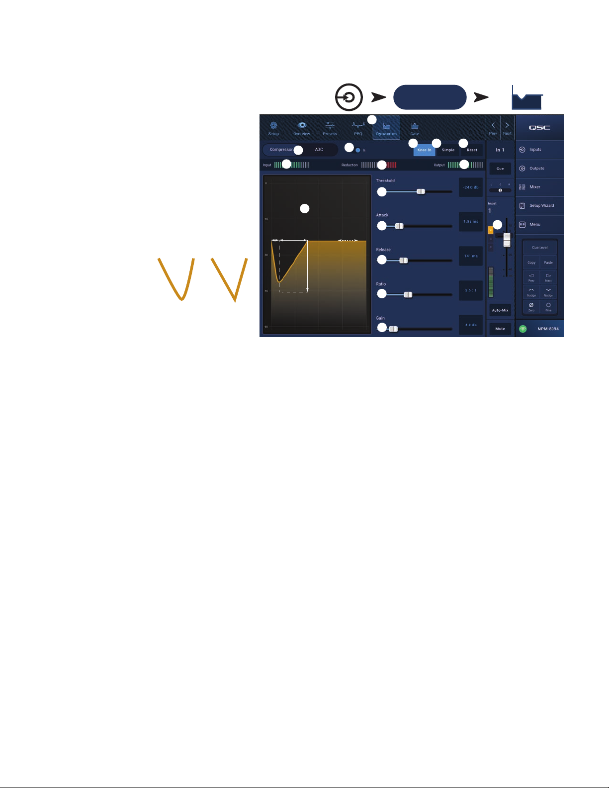
Input Channel − Dynamics
(Compressor / AGC)
The Input Channel Dynamics processing block may
be confi gured as either a Compressor or an Automatic
Gain Control (AGC).
Compressor
The Compressor controls the dynamic range of a signal
above a setThreshold.
1.
2.
3.
4.
5.
6.
7.
8.
meter – The red display indicates how much the signal is being reduced by the compressor. This meter displays a signal regardless
9.
10.
time (B to E) – The time it takes for the compression to reach its maximum compression after the input exceeds the thresholdlevel.
11.
12.
13.
14.
15.
16.
1
Dynamics
button – Selects the Compressor / AGC
screen.
Compressor / AGC
button – Selects either
Compressor or AGC.
In
switch – Engages and disengages the
Compressor or AGC processor.
Knee In
button –
Determines how
abruptly or gradually the
compressor transitions
in and out of gain
reduction as the threshold
In
iscrossed.
Simple
button – Turns Simple mode on and off.
When on, it hides all controlsexcept:
• Compressor / AGC
• Comp In
• Simple
• Reset
• Compression (Threshold)
All other controls remain at the value set prior to engaging the Simple mode button.
Reset
button – Sets all the Compressor and AGC controls, for this channel, to their factory defaultposition.
Input
meter – Displays the RMS input signal level.
Reduction
of whether the In button is engaged or not.
Output
Compressor
•
•
•
•
Threshold
Attack
Release
Ratio
Gain
Compressor in/out
meter – Output level after any applied compression
graph – Vertical scale from 0 dB to -60 dB; horizontal measurement is time. When engaged, the trace displays.
Threshold
(A) – The level at which compression begins.
Attack
Ratio
(A to E) – The amount of compression applied to the signal.
Release
time (C to D) – The time it takes for the compressed signal to rise to the threshold level once the input level no longer exceeds
thethreshold.
slider – Sets the point at which the compressor begins to reduce signal level.
slider – Adjusts how quickly the compressor reacts to a signal that exceeds the threshold.
slider – Adjusts how quickly the compressor stops compressing when signal falls below threshold.
slider – Sets the ratio of input level change to output level change when the signal exceeds the threshold.
slider – Adjusts the overall output gain to makeup any loss after the signal is compressed.
indicator – When the Compressor (or AGC) is In, an orange “C” displays on the channel controls strip.
Knee
Out
BEC D A
Inputs Touch an Input Bank
Mic/Line
(RCA / More)
2
7
10
3
8
11
12
13
14
15
4
6
5
9
Touch a Channel
Dynamics Button
16
TD-001578-01-B
13
Page 20
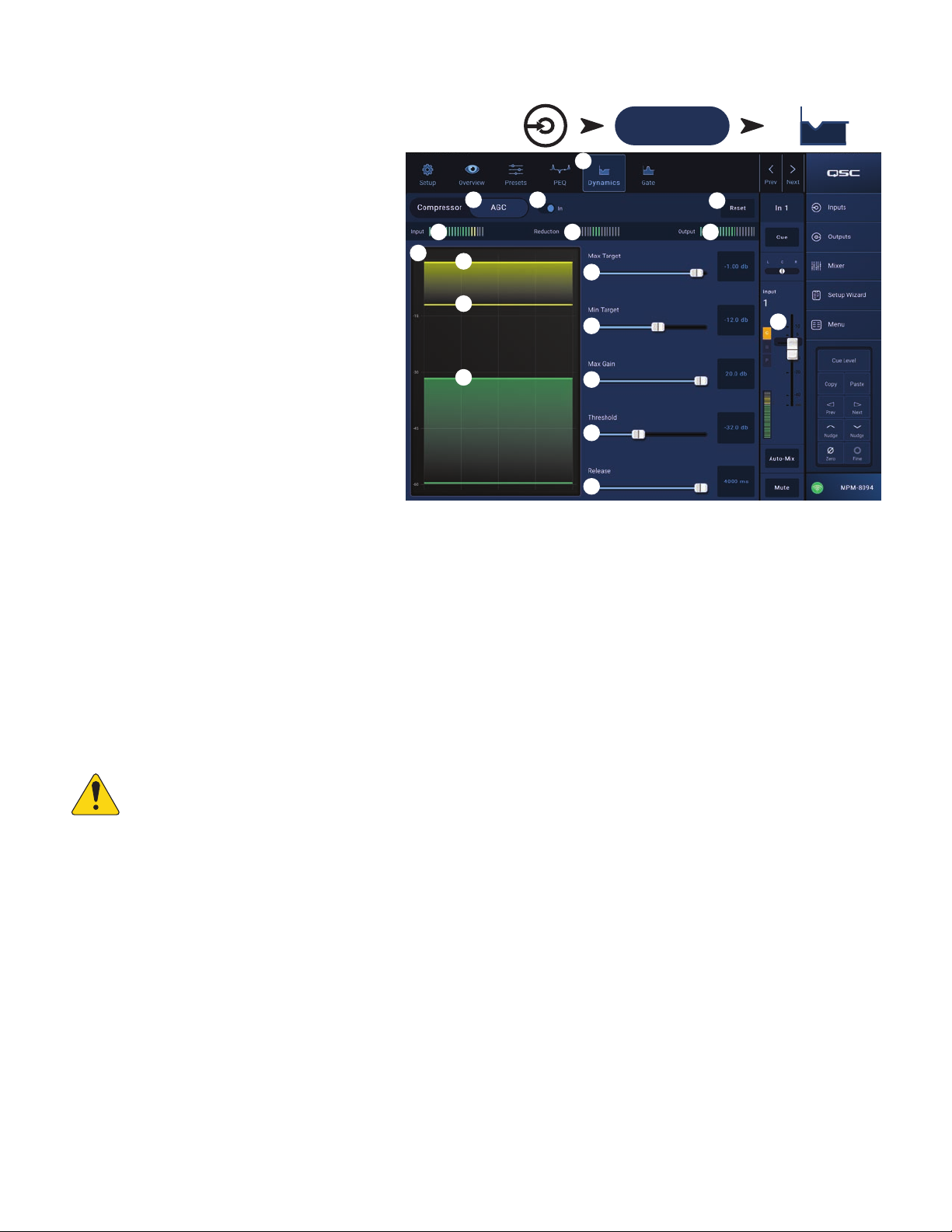
Automatic Gain Control (AGC)
The Automatic Gain Control is used to compensate for
variations in the audio level of the source material.
1.
Dynamics
2.
3.
4.
5.
6.
7.
8.
9.
10.
11.
12.
13.
14.
To Adjust the AGC
1.
2.
3. If some low-level passages of the program material are being boosted excessively, use the Max Gain control to decrease the maximum gain the
4.
1
button – Selects the Compressor / AGC
screen.
Compressor / AGC
button – Selects either
Compressor or AGC.
In
switch – Engages and disengages the
AGCprocessor.
Reset
button – Sets all the Compressor and
AGC controls, for this channel, to their factory
defaultposition.
Input
meter
–
Displays the RMS input signal level
Reduction
meter – Indicates how much the signal
level has been altered by the AGC. The center (0
dB) indicates that no gain change is being applied.
Rightward movement of the meter indicates that
gain is being applied. Leftward movement indicates
attenuation (reduction) of the signal level.
Output
after AGC has been applied.
AGC
meter – Indicates the output signal level
graph – Vertical scale from 0 dB to -60 dB.
When the AGC is engaged, the trace is displayed.
a.
Max Target
b.
Min Target
c.
Threshold
Max Target
Min Target
Max Gain
Threshold
– Indicates the maximum level that the AGC will maintain.
– Indicates the minimum level that the AGC will attempt to maintain.
– Indicates the level at which the AGC becomes active / inactive.
slider – Sets the maximum level that the AGC will maintain.
slider – Sets the minimum level that the AGC will attempt to maintain.
slider – Sets a limit on the amount of gain the AGC will apply regardless of the target settings.
slider – Sets the level at which the AGC becomes active / inactive. Signals that fall below the threshold level are assumed to be
intentional silence and the AGC will apply no additional gain.
Release
AGC
slider – Adjusts how long the AGC holds its gain change after the input signal level changes.
in/out indicator – When the AGC (or Compressor) is In, an orange “C” displays on the channel controls strip.
Touch
Inputs
Touch an Input Bank
Mic/Line
(RCA / More)
Touch a Channel
Dynamics Button
2
5
8
8a
8b
8c
3
6
9
10
11
12
13
4
7
14
NOTE:
The AGC should not be used on microphone inputs if there is any possibility of feedback.
Using program material that is slightly greater in level than the desired maximum signal level, adjust the Max Target slider until the Reduction
If the source device lacks an output volume control, use the input channel gain control to simulate low and high level playback. Use
the Cue output and headphones to listen to the results of the AGC.
indicates a slight amount of gain reduction by moving to the left of center.
Using program material that is slightly lower in level than the desired minimum signal level, adjust the Min Target slider until the Reduction
Meter indicates a slight amount of gain addition by moving to the right of center.
AGC applies.
With no program material playing, adjust the Threshold so that the Reduction Meter shows no additional gain being applied. This adjustment
prevents the AGC from applying full gain to residual noise from the sources when no signal is present.
TD-001578-01-B
14
Page 21
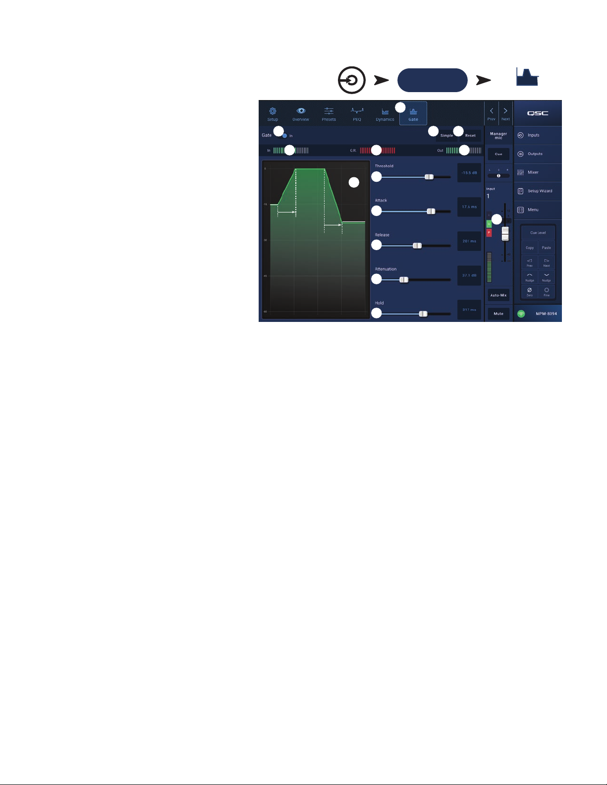
Input Channel − Gate
The Gate passes audio above a set Threshold, and
attenuates audio below the Threshold. In addition,
the Gate is used as part of the Store & Forward
pagingfunction.
1.
2.
3.
4.
5.
6.
7.
8.
9.
10.
11.
12.
13.
14.
Inputs Touch an Input Bank
Mic/Line
(RCA / More)
Touch a Channel
Gate Button
Gate
button – Selects the Gate Screen.
Gate In
Simple
switch – Engages or disengages the Gate.
button – Turns Simple mode on and off.
Hides all controlsexcept:
• Gate In button
• Simple button
• Reset button
• Gating slider
Reset
button – Sets all the Gate controls to their
factory default position.
In
meter – RMS input level
G.R.
meter – Gain Reduction – indicates how much
the signal is being reduced by the Gate.
Out
meter – Output level
Gate
graph – When the Gate is engaged, the trace
turns green. Horizontal axis is time, vertical axis
islevel.
• Threshold (A)
• Attack time (A-B)
• Release time (C-D)
• Attenuation Level (E).
Threshold
Attack
Release
Attenuation
Hold
slider – Sets the point at which the Gate allows audio to pass.
slider – Adjusts how quickly the gate reacts to a signal that exceeds the threshold.
slider – Adjusts how quickly the Gate attenuates the audio when signal falls below threshold.
slider – Sets the amount of attenuation applied to the output when the signal is below the Threshold.
slider – Sets the minimum time the Gate stays open once it is opened, and the length of time the Gate stays open after the input level
drops below the Threshold.
Gate in/out
indicator – When the Gate is In, a green “G” displays on the channel controls strip.
2
5
8
A
A
B
E
DC
1
3 4
6
9
10
11
12
13
7
14
TD-001578-01-B
15
Page 22
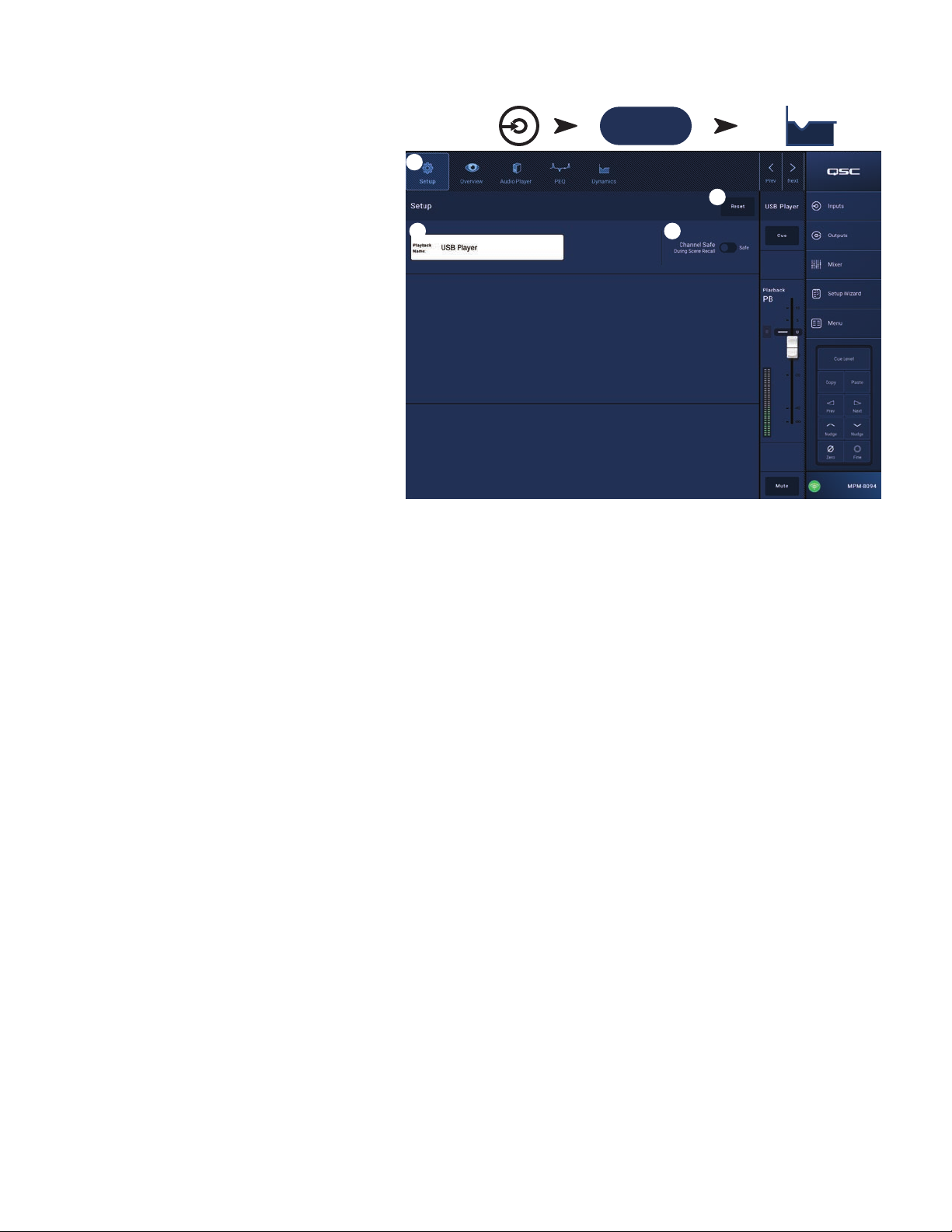
Input Channel − USB Player Setup
The setup screen includes a number of functions that are
primarily “set once and forget”. Channel Setup is provided
for all input channels.
1.
Setup
2.
3.
4.
button – Selects the Setup screen
Reset
button – Returns all Setup settings, for this
channel, to default values.
Input Name
fi eld – Displays the name of the channel.
Touch to display a keyboard and rename the channel
with a “friendly name”. Use only upper and lower case
alpha characters.
Channel Safe During Scene Recall
switch – When
set to Safe, the channel will not be affected by a
scenerecall.
Inputs Touch an Input Bank
More
1
3 4
Touch a Channel
Dynamics Button
2
TD-001578-01-B
16
Page 23
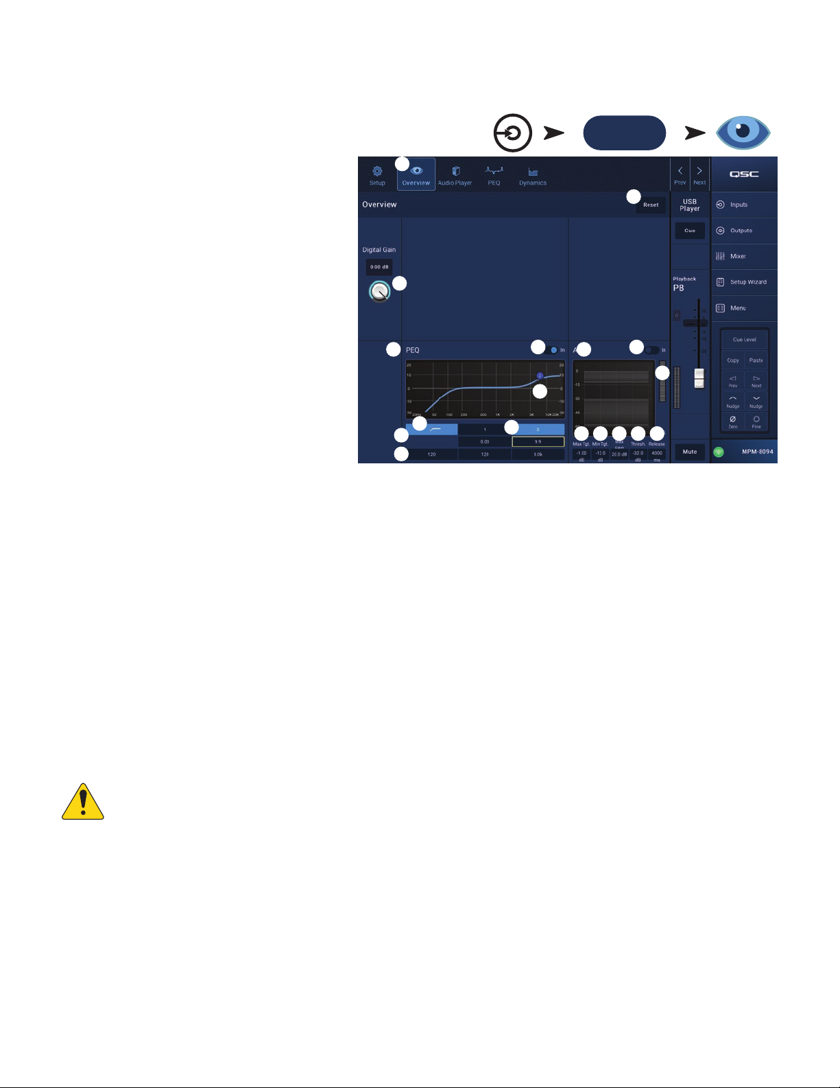
Input Channel − USB Player Overview
The Overview screen provides an abbreviated view of
each section in the Input Channel USB Player function.
Only the primary controls are available for adjustment in
theoverview.
1.
2.
3.
PEQ section
4.
5.
6.
7.
8.
9.
10.
Dynamics Section (AGC)
AGC is used to compensate for variations in the audio level of the source material.
11.
12.
13.
14.
15.
16.
17.
18.
Inputs
1
Touch Input Bank
More
More
Touch
Overview
Overview
Overviewscreen.
Reset
factory default position.
Digital Gain
fi les that are too low or high in level.
button – Selects the USB Player
button – Sets all the PEQ controls to their
knob – Compensates for digital audio
Parametric EQ
the equalization curve based on the PEQsettings. The
graph – A graphic representation of
trace dims to indicate that the PEQ is Out(disengaged).
EQ graph vertical scale
– Represents audio
•
level from -20 dB to+20dB.
EQ Graph horizontal scale
frequency from 20 Hz to 20 kHz.
EQ Out/In
EQ Handles
– Engages / disengages the equalizer.
– Touch, hold, and drag to change the
– Represents
•
Frequency and Gain of the associated frequency band.
The frequency band button must be engaged to see
the handles.
High Pass fi lter
button – Engages / disengages the high-pass fi lter. The HPF is variable with a range of 20 Hz to 2,000 Hz. It passes
frequencies above the setting while cutting those below.
Parametric Band 1 and 2
– Engages / disengages the associated parametric EQ band. Each band is fully parametric with a frequency range
of 20 Hz to 20 kHz.
Gain
control knobs and readouts – Adjusts the gain at the frequency setting of the associated fi lter. Range of -15 dB to +15 dB.
Freq
control knob – Sets the frequency of the associated fi lter.
2
3
4
7
9
10
5
8
11
6
14
12
13
15
16
18
17
AGC
display – Graphically shows the relationship of the controls as they are set.
AGC In
switch – Engages / disengages the AGC.
Reduction
meter – Indicates how much the signal level has been altered by the AGC. The center (0 dB) indicates that no gain change is being
applied. Rightward movement of the meter indicates that gain is being applied. Leftward movement indicates attenuation (reduction) of the
signal level.
NOTE:
Select a control then use the Nudge buttons to adjust.
Max Target
Min Target
Max Gain
AGC Threshold
control – Sets the maximum level that the AGC will maintain.
control – Sets the minimum level that the AGC will attempt to maintain.
control – Sets a limit on the amount of gain the AGC will apply regardless of the target settings.
control – Sets the level at which the AGC becomes active / inactive. Signals that fall below the threshold level are assumed to
be intentional silence and the AGC will apply no additional gain.
Release
control – Adjusts how long the AGC holds its gain change after the input signal level changes.
Refer to the AGC topic for complete details.
TD-001578-01-B
17
Page 24
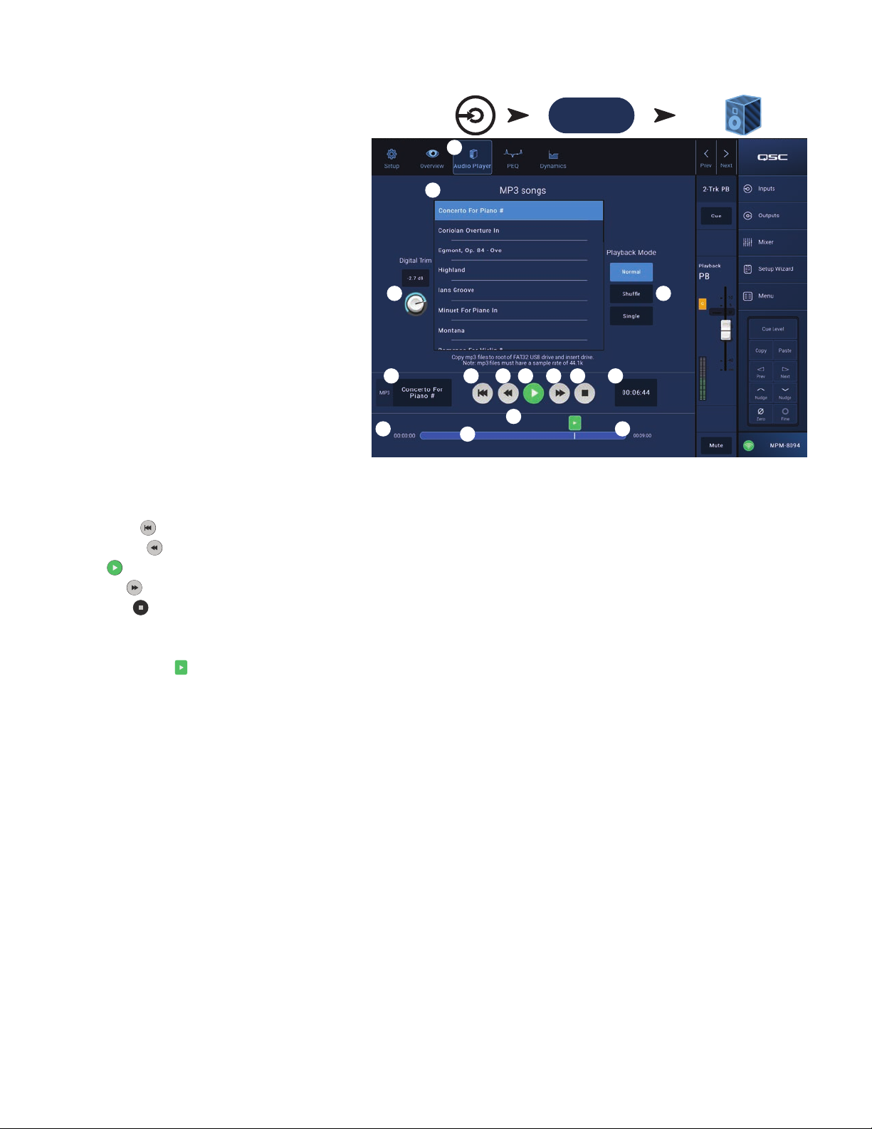
Input Channel −
USB
Player
Use the USB Player for MP3 playback from a USB storage
device attached to one of the MP-M USB ports.
•
•
•
•
•
1.
2.
3.
4.
5.
6.
7.
8.
9.
10.
11.
12.
13.
14.
15.
Inputs
Touch Input Bank
More
More
Touch Audio Player
Button
The USB storage device must be formatted FAT32.
The audio fi les must be in the root directory.
Files are displayed in alpha-numeric order.
MP3 fi les must have a sample rate of 44.1k.
USB Playback must be enabled from Menu > Settings
in order for this feature to be available for the MP
Manage app.
Audio Player
button – Selects the Audio
Playerscreen.
MP3 Songs
– Displays a list of MP3 titles on the
inserted USB drive.
Digital Trim
– Provides input gain control. (-12 dB to
0.00 dB)
Playback Mode
•
Normal
–
button – plays the fi les in listed order
(alpha-numeric)
•
Shuffl e
•
MP3
Top-of-List – Touch to move to the beginning of the fi lelist.
Previous fi le – Touch to move to the previous fi le in the fi le list.
Play – Touch to begin playback of the currently selected MP3 fi le.
Next fi le – Touch to move to the next fi le in the fi le list.
Stop Play – Touch to stop playback of the currently selected MP3 fi le.
Playback Time – Indicates elapsed time since beginningplayback.
Progress Line indicates the approximate playback position in the fi le.
button – plays the fi les in random order.
Single
button – plays the selected fi le one time. Does not repeat.
– Displays title of currently selected MP3 fi le.
Position Progress – Touch, hold, and drag to desired position on the Progress Line.
00:00:00 – Represents the start of the fi le.
HH:MM:SS – Indicates the length of the fi le.
3 4
5
12
1
2
8
9
7
6
14
13
10
11
15
TD-001578-01-B
18
Page 25

Input Channel − USB Player PEQ
This screen controls and displays the settings for the
Input Channel 2-Trk PB parametric equalization.
The PEQ is a 2-band, high / low shelving EQ that
includes variable HPF (High Pass Filter).
The HPF cuts frequencies from 20 Hz to 2,000 Hz (low
cut) and passes frequencies above 2,000 Hz (high
pass).
1.
2.
3.
4.
5.
6.
7.
8.
9.
10.
11.
12.
Touch the
Touch a Channel
PEQ
button – Selects the EQ screen.
EQ Out/In
RTA On
– Engages / disengages the equalizer.
– Engages / disengages the a real time
analyzer. The RTA displays the tonal balance of the
channel’s signal. Peak hold indicators are displayed
for each band.
The RTA is currently being
NOTE:
Only one
RTA may be
running on the
system at a time.
used by [device name]. Do
you want to assign it in-
stead to this device?
Yes No
Touch the RTA
button. If another device is using the RTA,
the message to the right displays.
Inputs
More button
PEQ Button
More
2
5
6
8
9
1
10
11
12
3 4
7
NOTE:
Reset
button – Sets all the PEQ controls to their factory default position.
RTA
display – Displays the amplitude of the channel signal in 1/3 octave bands. Peak hold indicators are displayed for each band.
•
RTA
•
RTA
Parametric EQ
When the RTA is off, the Parametric EQ graph expands to use the entire graph area.
graph vertical scale – Represents audio level from -60 dB to-5dB.
graph horizontal scale – Represents frequency from 31.5 Hz to 16 kHz.
graph – A graphic representation of the equalization curve based on the PEQsettings. The trace dims to indicate that the PEQ
is Out(disengaged).
•
EQ
graph vertical scale – Represents audio level from -20 dB to+20dB.
EQ
Graph horizontal scale – Represents frequency from 20 Hz to 20 kHz.
•
EQ
handles – Touch, hold, and drag to change the Frequency and Gain of the associated frequency band. The frequency band button must be
engaged to see the handles.
High Pass
High Pass Freq
Low Shelf and High Shelf
fi lter button – Engages / disengages the HPF (described above).
control knob – Sets the frequency of the high pass fi lter (20 Hz to 2,000 Hz). The frequency reading is taken at -3 dB.
fi lter buttons – Engages / disengages the low and high shelving fi lters. The low shelving fi lter raises or lowers a
range of frequencies below the set frequency. The high shelving fi lter raises or lowers a range of frequencies above the set frequency.
Gain
control knob and readout – Adjusts the gain at the frequency setting of the associated shelving fi lter. Range of -15 dB to +15 dB.
Freq
control knob (Low and High Shelving) – Sets the frequency of the low / high shelving fi lter.
TD-001578-01-B
19
Page 26

Input Channel – USB Dynamics Automatic Gain Control (AGC)
The Automatic Gain Control is used to compensate for
variations in the audio level of the source material.
1.
2.
3.
4.
5.
6.
7.
8.
9.
10.
11.
12.
13.
To Adjust the AGC
1.
2.
3. If some low-level passages of the program material are being boosted excessively, use the Max Gain control to decrease the maximum gain the
4.
Touch
1
Inputs
Touch Input
Bank More
More
Touch the
Dynamics Button
Dynamics
AGC In
button – Selects the AGC screen.
switch – Engages and disengages the
AGCprocessor.
Reset
button – Sets all the AGC controls, for this
channel, to their factory defaultposition.
Input
meter
–
Displays the RMS input signal level
Reduction
meter – Indicates how much the signal
level has been altered by the AGC. The center (0
dB) indicates that no gain change is being applied.
Rightward movement of the meter indicates that
gain is being applied. Leftward movement indicates
attenuation (reduction) of the signal level.
Output
meter – Indicates the output signal level
after AGC has been applied.
AGC
graph – Vertical scale from 0 dB to -60 dB.
When the AGC is engaged, the trace is displayed.
a.
Max Target
– Indicates the maximum level
that the AGC will maintain.
b.
Min Target
– Indicates the minimum level that
the AGC will attempt to maintain.
c.
Threshold
Max Target
Min Target
Max Gain
Threshold
slider – Sets a limit on the amount of gain the AGC will apply regardless of the target settings.
slider – Sets the level at which the AGC becomes active / inactive. Signals that fall below the threshold level are assumed to be
– Indicates the level at which the AGC becomes active / inactive.
slider – Sets the maximum level that the AGC will maintain.
slider – Sets the minimum level that the AGC will attempt to maintain.
intentional silence and the AGC will apply no additional gain.
Release
AGC
slider – Adjusts how long the AGC holds its gain change after the input signal level changes.
in/out indicator – When the AGC is In, an orange “D” displays on the channel controls strip.
2
4
7
7a
7b
7c
5
8
9
10
11
12
3
6
13
NOTE:
The AGC should not be used on microphone inputs if there is any possibility of feedback.
If the source device lacks an output volume control, use the input channel gain control to simulate low and high level playback. Use
the Cue output and headphones to listen to the results of the AGC.
Using program material that is slightly greater in level than the desired maximum signal level, adjust the Max Target slider until the Reduction
indicates a slight amount of gain reduction by moving to the left of center.
Using program material that is slightly lower in level than the desired minimum signal level, adjust the Min Target slider until the Reduction
Meter indicates a slight amount of gain addition by moving to the right of center.
AGC applies.
With no program material playing, adjust the Threshold so that the Reduction Meter shows no additional gain being applied. This adjustment
prevents the AGC from applying full gain to residual noise from the sources when no signal is present.
TD-001578-01-B
20
Page 27

Output Zones
Output Zone – Block Diagrams
Mono Zone
Stereo (Linked) Zone
To Zone
Outputs
Outputs
Routing
Matrix
Sources: From inputs, mixer, other zones, USB, wireless paging
Mono Input
Stereo Input
Primary Source
Level
Polarity
Touch Inputs
Zone
GEQ
Φ
Custom Loudspeaker Tuning
Override
Zone
Level
QSC
Tuning
Low Cut High CutPEQ
Limiter
Auto
Loudness
Delay
Cue
DAC
To Cue
Sources: From inputs, mixer, other zones, USB, wireless paging
Mono Input
Stereo Input
Mono Input
Stereo Input
Mono Input
Stereo Input
Mono Input
Stereo Input
Mono Input
Stereo Input
Mono Input
Stereo Input
Mono Input
Stereo Input
Mono Input
Stereo Input
Mono Input
Stereo Input
Mono Input
Stereo Input
Mono Input
Stereo Input
Secondary Source
Level
Source 1
Level
Source 2
Level
Source 3
Level
Source 4
Level
Primary Source
Level
Secondary Source
Level
Source 1
Level
Source 2
Level
Source 3
Level
Source 4
Level
Polarity
Ducker
1
Source
Select
Ducker
1
Source
Select
Φ
Ducker 2Ducker
MP-M40: 4 of 8 potential sources shown
MP-M80: 4 of 16 potential sources shown
GEQ
Bypass
Zone
Level
Ducker
2
1
QSC
Tuning
Custom Loudspeaker Tuning
Ducker
1
Low Cut High CutPEQ
From
System
Test
Signal
Generator
From
System
Test
Signal
Generator
Output
Level
Limiter
Loudness
Auto
Gain
Gain
Gain
Gain
Output
Level
Delay
Cue
DAC
DAC
Routers
Zone
Follows
Zone
Zone
To Cue
TD-001578-01-B
MP-M40: 4 of 8 potential sources shown
MP-M80: 4 of 16 potential sources shown
21
Page 28

Output Zones – Home Screen
The Outputs Home screen displays the processing blocks for
the output channels. Touch any block to see the associated
controls and displays for the Output Zone processing block.
1.
Zones
2.
3.
4.
5.
6.
/
Music on Hold
(MP-M80 shown) – Zones
displays the Zones (output channels) and processing
block for the corresponding Zones. Music on Hold
displays the Music on Hold output channel and its
processing blocks.
Titles for the processing block columns.
Linked stereo processing block.
Mono processing block.
Light-colored blocks (highlighted) indicate that the block
is engaged.
Dark-colored blocks indicate that the block is
notengaged.
1
2
3
6
4
5
TD-001578-01-B
22
Page 29

Output Zone − Navigation &
Master Controls
Output Zone Navigation Icons
The icons at the top of the screen display when you select
a channel. Use these to navigate to other processing
blocks for the output channel. These icons remain visible
when an output channel-processing block isselected.
1.
Setup
2.
3.
4.
5.
6.
7.
8.
9.
Output Zone Master Controls
To the right of the screen are the channel’s Master controls and indicators. These controls remain visible no matter which output channel’s
processing block is selected.
10.
11.
12.
13.
14.
15.
16.
17.
3 4
1
96
8
5
2 7
– The Setup screen provides controls to change
the channel name, link channels, set Channel Safe and
set the delay.
Overview
– The Overview screen displays and
provides controls for most of the settings for the
selected channel.
Sources
– The Sources screen provides controls
to select the sources and their priority for the
selectedchannel.
Speakers
– The Speakers screen provides controls
to select, recall, save custom settings, and sets which
parameters of a preset to recall.
GEQ
– The GEQ screen provides a 28 band GEQ and
an RTA display.
Anti FB
– The Anti-Feedback screen provides controls
to set automatic anti-feedback, or manual kill, and provides a wizard for automatically fi nding feedback-prone frequencies.
Loudness
Limiter
Prev / Next
– The Loudness screen provides controls to maintain a constant perceived tonal balance when the output level setting isadjusted.
– The Limiter screen provides controls to limit the output level.
buttons – Navigates to adjacent channels. The overall movement is circular; when the last channel is reached, continue in the
same direction to start over.
Touch
Outputs
Touch Setup
10
11
12
13
14
15
16
17
Zone label
Cue
Output Channel label
L
– Indicates that the Limiter for the channel is engaged or not.
AF
Fader
Meter
Mute
– Displays the name entered in the Setup Output Name fi eld.
– Sends the channel signal to the Cue headphone output.
– Displays the system number for the Output channel.
– Indicates that the Anti-Feedback Filters for the channel are engaged or not.
– Adjusts the output level of the channel.
– Indicates the channel signal level.
– Mutes and indicates mute status of the channel.
TD-001578-01-B
23
Page 30

Output Zones − Setup / Delay
Various utility setup functions for Aux and Main
outputchannels.
1.
Setup
2.
About Stereo Linking:
Signal routing and summing for linked inputs and outputs
functions as follows:
•
•
•
•
3.
4.
5.
6.
7.
8.
9.
About Delay:
The output delay on the MP-M is primarily useful for “architectural delay”. Architectural delay is used to align the arrival of sound from nearby speakers
to the arrival of sound from a more distant source. When the delay is set correctly, the listeners will have the impression that they are hearing the distant
source when most of what they hear is actually coming from the nearby speakers. To adjust the delay:
•
•
•
button – Selects the Setup screen
Stereo Link
– Links adjacent channels for stereo
operation. Only odd / even linking is supported (1-2, 3-4,
etc.). Even / odd linking (2-3, 4-5) is not available.
Touch
Outputs
1
2
4
5
6
3
Touch Setup
Mono input (source) to mono output (zone) – The mono
source signal is output from the zone as a mono signal.
Mono input (source) to stereo linked output (zone) – The
mono source signal is routed equally to the odd and even
numbered outputs.
Stereo input (source) to mono output (zone) – The stereo
source signal is summed and output to the zone as a
mono signal.
Stereo input (source) to stereo linked output (zone) –
The stereo source signal from the odd numbered input
channel is routed to the odd numbered output channel.
The stereo source signal from the even numbered input channel is routed to the even numbered output channel.
Reset
– Returns Setup parameters to factory defaultvalues.
Output Name
Polarity
Channel Safe
Min/Max Output
– Displays the name of the output channel. Touch to display a keyboard and rename the output as needed.
– Engage to reverse the channel’s polarity.
– When set to Safe, the channel will not be affected by a scene recall.
– Sets a minimum and maximum level for the channel. These are the minimum and maximum settings that can be set from an
MFC or from the MP Manage app. On the MFC and MP Manage app, the Min setting is displayed as 0% and the Max setting is displayed as 100%.
Architectural Delay
Delay Enable
– is variable up to 100 msec and is displayed in feet, meters and milliseconds.
– Engages or disengages the Delay.
7
8
9
Set the delay for the nearby speakers so that the distance equals the distance between the nearby speakers and the distant source. Note that the
source could be an acoustic source such as a piano, guitar or a talker, or it could be another speaker system.
Get into the coverage area of the nearby speaker. While listening to the source and the nearby speaker, add up to 30 msec. of delay. You’ll know it’s
right when you’re ear tells you that the sound is coming from the source.
Precedence Effect (also known as Haas Effect) creates the illusion that we aren’t hearing the delayed sound from the nearby speakers because we
heard the sound from the distant source fi rst.
TD-001578-01-B
24
Page 31

Output − Music On Hold (MoH)
The MP-M has the ability to route an input signal to a
dedicated Music on Hold output that can be connected to a
telephone system.
Note that the MoH output audio bandwidth has been
deliberately limited to reduce distortion that may
occur if excessive low-frequency signal is sent to a
telephonesystem.
1.
2.
Touch
Outputs
Touch
Music On Hold
Music On Hold
Touch
Setup
Select Source
– Touch a source from the
scrollablelist.
Adjust the level control to the desired output level.
1
2
TD-001578-01-B
25
Page 32

Output Zone − Overview
The output overview provides an aggregated, “at a glance”
view of channel settings. Most of the controls are present
on other processing blocks and will be described in detail
in the sections covering their respective functions.
1.
2.
3.
4.
5.
6.
7.
8.
9.
10.
11.
12.
e.
Release
readout control – Touch to select; use the Nudge controls to adjust
Outputs Touch Zones
1
Touch a Channel
Overview Button
Zones
Overview
button – Touch to select the
Overviewscreen.
Preset
button – Displays the name of the currently
loaded output channel preset. Touch to open the
Presetscreen.
Reset
button – Returns the Zone output channel to
factory default setting.
Sources
from the Presets screen.
a.
b.
c.
Anti-Feedback In
anti-feedback fi lters.
Stereo Link
Tuning
Min
a. Readout controls – Displays the current setting. Touch the readout and use the Nudge controls to adjust.
– Displays the names of the sources selected
Primary
display button – Touch to change the
primary source.
Secondary
display button – Touch to change the
secondary source.
Active
display button – Touch to change the
active source.
switch – Engages / disengages the
display button – Indicates if the output is linked to the adjacent channel. Touch to toggle Stereo Link on and off.
display button – Displays the name of the currently loaded loudspeaker tuning. Touch to select a different tuning.
/
Max Output
–
b. Sliders – Adjust the minimum and maximum output level for the output. Touch and drag to adjust.
Loudness
–
a. In switch – Engages / disengages Loudness compensation and
b. Slider – adjusts the Threshold.
Delay
–
a. Knob – Adjusts the output delay.
b. Button – Enables / disables the output Delay.
GEQ –
a. In switch – Engages / disengages the GEQ.
b. Sliders – Displays and allows adjustment of the settings for the output’s graphic equalizer.
Limiter
–
a. In switch – Engages / disengages the Limiter.
Limiter
b.
c.
d.
graph – Displays the settings for the limiter.
Threshold
Attack
readout control – Touch to select; use the Nudge controls to adjust.
readout control – Touch to select; use the Nudge controls to adjust .
10a
10b
2
4a
6
4b
7
8a
8b
11b
4c
11a
12c 12e
3
5
9a
9b
12a
12b
12d
TD-001578-01-B
26
Page 33

Output Channel − Sources
A primary purpose of the MP-M is to route audio signals
from the inputs (Sources) to the outputs (Zones). The
Sources screen is where the available sources are
assigned to an output and given their roles.
The MP-M uses Priority Sources to designate which inputs
are able to override the signal from other inputs. Each
output zone includes two duckers that are triggered by the
Priority inputs. (A ducker is a dynamic processor that uses
one audio signal to reduce the level of another signal.)
Assignments to sources are made from MP Install and
cannot be changed from the MP Manage app or the
MFCcontrollers.
•
•
1.
2.
Priority Sources
3.
4.
5.
6.
output’s master level control. This allows, for example, a page message to be heard at a pre-set volume no matter what the zone’s level setting
7.
8.
9.
Selectable Sources
A single output (Zone) may have up to 8 Selectable Sources assigned to it.
10.
11.
Silence – Silence may be selected as a means of muting an output. If silence is selected, the Priority sources will still function normally.
None – None is the default selection. If None is the source for any of the 8 available source selection ‘slots’, that slot will not appear on
12.
A signal arriving at the Primary input will reduce the
level of the Secondary Source and the Selectable
Sources audio.
A signal arriving at the Secondary input will reduce the
level of the Selectable Sources audio but will not affect
the Primary Source input.
Outputs Touch Zones
Touch a Channel
Sources Button
Zones
4
5
7
8
1
2
10
3
6
11
12
Sources
Reset
button – Selects the Sources screen.
button – Returns all controls on the Sources
9
screen to their factory default.
Primary
Source select
Source Level
Override Zone Level
/
Secondary
switch – Selects either the Primary source selection and setup, or the Secondary source selection and setup.
button – Touch the drop-down menu to display and select from a list of available sources for the priority input.
– Sets volume level for the Primary or Secondary signals relative to the other zone inputs.
(Primary Source only) – When the switch is set to the Yes position, the Primary Source level will not be affected by the
may be.
Threshold
Depth
Hold
– Sets the level that the priority source must reach to trigger ducking.
– Sets the amount of attenuation applied to the Selectable Source when ducking is triggered.
– Determines how long attenuation is applied after the Priority input signal drops below Threshold.
On
– Selects the associated source as the active source for the output.
Selectable Source
buttons – Touch one of the selection buttons to display and select from a list of available sources. Available sources are:
• Any input channel
• The output from the internal mixer section of the MP-M.
• Any other output zone or “Zone-Follows-Zone”. This function is used, for example, if a single area of a facility has different kinds of
loudspeakers (full-range / subwoofer) that require differing processing but it’s desirable for the entire area to operate as a single zone.
It can also be used for room combining in facilities with movable air walls.
•
•
MP Install or on the MFC controllers.
Level
– Adjusts the level of each source relative to the other sources.
TD-001578-01-B
27
Page 34

Output Zone − Presets
The Presets screen is used to perform these tasks:
•
•
•
Factory Loudspeaker Library
When Factory / User is set to Factory, a list of QSC
loudspeakers is displayed. Factory tunings for QSC
loudspeakers use a processing block, comprised of FIR
and IIR fi lters, that is not user accessible.
Recalling a factory-tuned loudspeaker also recalls all of the
factory default channel settings unless the Recall Omits
have been set. (See item 6 below.)
To recall a QSC loudspeaker preset:
To clear a preset:
Controls:
1.
2.
3.
4.
5.
6.
– When an Output Channel Preset is saved, all output channel settings are saved with the preset. The Recall Omits section allows
7.
button – Loads the loudspeaker tuning selected from the Series, Type and Preset panel. If “Default” is selected, the factory tuning fi lters
8.
9.
10.
Outputs Touch Zones
1
Touch a Channel
Presets Button
Creating, saving and recalling custom loudspeaker
tunings using the provided Filters and PEQ.
Saving and recalling output channel settings.
Recalling preprogrammed QSC loudspeaker tunings.
a. Select a loudspeaker series from the
A list of QSC models from the selected series is
displayed in the Type panel.
b. Select a
Type
(model) from the Type panel.
Some loudspeaker models may have variations on
the basic tuning for use in different applications. These variations will be shown in the Preset Name panel.
c. Make a selection from the
d. Touch
Recall
to load the preset.
Preset Name
a. Scroll to the top of the Series panel, select (Default)
b. Touch
Presets
Filters/PEQ
in addition to the factory tuning to “season to taste”.
Preset Info
Current Preset
Factory / User
Recall Omits
some settings to remain unchanged when the preset is recalled.
a.
b.
c.
Recall
.
button – Opens the Presets screen.
button – Opens the Filters/PEQ screen (described below) where custom tunings can be created. This equalizer may also be used
button – Displays a text box with information about the selected preset.
fi eld – Displays the name of the currently loaded loudspeaker preset.
switch – Touch User to open a screen where custom user tunings and presets are stored and managed.
Omit Levels and Sources
Omit Speaker Tuning
Omit Processing Blocks
switch – Level and Source assignments are not affected by the preset recall.
switch – The factory and user tunings are not affected by the preset recall.
switch – The GEQ, Anti-Feedback, Loudness, and Limiter are not affected by the preset recall.
Recall
will be set to fl at.
Series
panel – A listing of selectable QSC loudspeaker families or Series.
Type
panel – A listing of selectable loudspeaker Types or models belonging to the selected Series.
Preset Name
panel – A listing of available presets for the selected Series and Type.
Series
panel.
panel.
Zones
2
5
8
3
6
6a 6b 6c
4
7
109
TD-001578-01-B
28
Page 35

User Presets
The User Preset screen is where custom user tunings and
presets are stored and managed.
1.
2.
3.
4.
5.
One item in the App Storage list, MP-M Internal list, or the USB External list must be selected for the following controls to be available.
6.
7.
8.
9.
10.
Outputs Touch Zones
Zones
Touch a Channel
Presets Button
NOTE:
Controls described below are
unique to the User Preset Library screen.
Descriptions of controls which are visible on
this screen, but not described below, may
be found in the Factory Loudspeaker Library
topic or the Filters / PEQ topic.
Save / Save As
to save all output channel settings to the internal
MP-M memory, or a USB device attached to the
MP-M. When a preset is saved, it becomes the
CurrentPreset.
button – Opens a dialog box used
TIP:
If a Factory Loudspeaker preset is
recalled, it can then be saved as a user
preset. This can be used as a start on which
to build custom presets.
a.
Save Preset As
fi eld – touch the fi eld to access
a keyboard and enter a different name for the
preset or, leave the name as it is, and continue to the next step.
b.
Storage Location
switch – Select either MP-M Internal (on the mixer), or USB attached
to the mixer.
c. Save button – Touch the button to save the preset in the selected location.
d. Cancel button – Touch the button to exit the dialog without saving the preset.
Factory / User
switch – When set to User, the User Loudspeaker Preset Library screen
isdisplayed.
App Storage
list - Displays any user presets stored in the internal memory of the device
being used to control the MP-M. When this panel is selected, the Copy to MP-M button will
copy the preset to MP-M internal memory. You cannot Recall a preset from App Storage. To
Recall, save the preset to MP-M Internal, then Recall.
MP-M Internal
list – Displays any user presets stored in the MP-M internal memory. When this panel is selected, the selected Preset can be
copied to either the App Storage or USB External. In addition, the Preset can be recalled, then be saved or saved as a different preset.
USB External
list – Displays any user presets stored on a connected USB device. When this panel is selected, the selected Preset can be
copied to the MP-M Internal storage. In addition, the Preset can be recalled, then can be saved or saved as a different preset.
2
3 4
1
11
5
6
8
10
7
9
1a
1b
1c 1d
Copy To MP-M
Copy to USB
Copy To App
Copy to MP-M
Delete
button – Deletes the selected preset.
button – Touch to copy a selected preset from the App Storage to the MP-M Internal storage.
button – Touch to copy a selected preset from the MP-M Internal storage to the USB storage.
button– Touch to copy a selected preset from the MP-M Internal storage to the App Storage.
button– Touch to copy a selected preset from the USB External storage to the MP-M Internal storage.
TD-001578-01-B
29
Page 36

Filters / PEQ
The Filters / PEQ screen provides the tools to create
custom speaker presets.
The PEQ is a 6-band, fully parametric EQ that includes
variable HPF (High Pass Filter) & LPF (Low Pass Filter) and
High and Low Shelving Filters.
1.
2.
3.
4.
5.
6.
7.
8.
9.
10.
11.
12.
fi lter buttons – Changes EQ Band 1 and Band 6 from parametric fi lters to shelving fi lters. When a shelf fi lter is engaged,
13.
14.
15.
16.
17.
Outputs Touch Zones
Touch
Filters / PEQ
Touch a Channel
Presets Button
Filters / PEQ
Button
PEQ button – Selects the EQ screen.
Presets In – Engages / disengages the equalizer.
Filters / PEQ button – Opens or closes the Filters /
PEQ screen.
LPF/HPF button – Available only when the Filters / PEQ
screen is open. Touch to display a dialog for setting the
HPF and LPF slope and type.
a. Select either Butterworth or Linkwitz-Riley for both LPF
and HPF.
b. Select the slope per octave: 12 dB, 18 dB, or 24 dB
for each.
c. Touch the Close button to close the dialog box.
Changes are saved.
RTA On – Engages / disengages the real time analyzer
that displays the tonal balance of the channel’s signal
including peak hold indicators.
NOTE:
Only one RTA may be running on the system at a time. Touch the RTA button. If
another device is using the RTA, the message “The RTA is currently being used
by (device name) Do you want to assign it instead to this device?”
NOTE:
When the RTA is off, the Parametric EQ graph expands to use the entire
grapharea.
2 7
8
9
12
11
17 16
3 4
10
Zones
1
5
6
13
14
15
12
11
17
1
2
Simple button – Hides the Frequency, and Q controls for all bands and low and high cut fi lters.
3
Changing to Simple mode does not affect existingsettings.
Reset button – Sets all the PEQ controls to their factory default position.
RTA display – Displays the amplitude of the channel signal in 1/3 octave bands. Peak hold indicators are
displayed for each band. The vertical scale represents audio level from -60 dB to-5dB. The horizontal scale represents frequency from 31.5 Hz to 16 kHz.
Parametric EQ graph – A graphic representation of the equalization curve based on the PEQsettings. The trace dims to indicate that the PEQ is
Out(disengaged). The vertical scale represents audio level from -20 dB to+20dB. The horizontal scale represents frequency from 20 Hz to 20 kHz.
EQ handles – Touch, hold, and drag to change the Frequency and Gain of the associated PEQ band. The frequency band button must be engaged to see
the handles.
High Pass and Low Pass buttons – Engages / disengages the HPF and LPF. The HPF is variable with a range of 20 Hz to 2,000 Hz. It passes
frequencies above the setting while cutting those below. The LPF is variable with a range of 1 kHz to 20 kHz. It passes frequencies below the setting while
cutting those above.
Low Shelf and High Shelf
the Q control is not available. The low shelving fi lter raises or lowers a range of frequencies below the set frequency. The high shelving fi lter raises or
lowers a range of frequencies above the set frequency. Bands 1 and 6 and their respective shelving buttons must be “on” for the shelving fi lters to work.
Frequency Bands 1, 2, 3, 4, 5, and 6 buttons – Engages / disengages the associated parametric EQ band. Each band is fully parametric with a
frequency range of 20 Hz to 20 kHz.
Gain control knob and readout – Adjusts the gain at the frequency setting of the associated EQ band. Range of -15 dB to +15 dB.
Freq control knob (Frequency bands 1 – 6) – Sets the center frequency of the associated EQ band. If the Shelving fi lter is engaged, the Freq control sets
the knee frequency of the shelf fi lter.
Q knob – Adjusts the Q of the associated EQ band. When the Shelf Filter is selected, the Q control is hidden. In addition, Q can be adjusted by “pinching”.
Freq control knob (Low and High Cut) – Sets the frequency of the low and/or high cut fi lter as measured from a point 3 dB below 0 or unity.
TD-001578-01-B
30
Page 37

Output Zone − Graphic Equalizer (GEQ)
Each output includes a 1/3 octave graphic equalizer (GEQ)
that may be used to adjust the tonal balance of the output.
1.
GEQ
2.
3.
4.
5.
button – Touch to access the GEQ.
Graphic Equalizer In
switch – Engages / disengages
the GEQ.
RTA On
button – Touch to activate / deactivate a Real
Time Analyzer display for the output. When the RTA
is not enabled, the GEQ screen is enlarged to occupy
both the RTA and GEQ screen area.
Reset
– Sets all GEQ faders to 0 (fl at).
GEQ Band
sliders – Touch and drag a slider to change
the amplitude of the selected frequency band. Use the
Nudge buttons and Fine button for greater precision.
Touch
Outputs
2
1
3 4
5
Touch GEQ
TD-001578-01-B
31
Page 38

Output Zone − Anti-Feedback
For applications in which microphones will be used for live
sound reinforcement, the MP-M includes twelve narrowband, anti-feedback fi lters on each output. These fi lters
are extremely useful for eliminating feedback frequencies
while having very little effect on overall tonal balance. The
fi lters may be adjusted manually or automatically using the
“Feedback Wizard”.
1.
2.
3.
4.
5.
button – Sets all the Filter controls and markers to their factory default position. Note that the Feedback Wizard will only use a fi lter if its
6.
7.
8.
9.
10.
11.
12.
Filter Q –
Adjusts the width of the fi lter from a Q of 10 to a Q of 30.
Touch
Outputs
Touch an Anti-
Feedback button
Output Zone – Presets
1
2
3 4
5
NOTE:
In most situations, it is not necessary
to use all 12 fi lters to achieve a stable
system. Typically, 4 – 6 fi lters will be
suffi cient. Use of more fi lters may degrade
sound quality unnecessarily.
Anti-Feedback In
thefi lters.
Feedback Frequency
system automatically identifi es and displays suspected
feedback frequencies in real time.
Manual Kill
frequency is identifi ed, touching this button applies a
fi lter at that frequency. The fi lter marker selected is
simply the fi rst available marker numerically.
Wizard
button – Touching this button opens the Feedback Wizard which will guide the operator through the anti-feedback process.
button – Engages / disengages
readout – The Anti-Feedback
button – When a suspected feedback
Reset
Cut has been set to0.0.
Display
– Shows the frequency and depth (cut) of applied fi lters.
•
Vertical scale
•
Horizontal scale
Filter markers
amount of cut is indicated by a descending vertical line.
= dB
= frequency
– These markers are color-coded to correspond with their associated controls. Horizontal position indicates frequency. The
6
7
8
9
10
11
12
NOTE:
Markers and their associated frequency controls are not tied to a specifi c frequency band. Marker 1 may attenuate a high
frequency, while Marker 12 may attenuate a low frequency.
Filter
In/Out – The numbered buttons engage/disengage the fi lters. When a fi lter is disengaged, the associated marker is not displayed.
Freq
– Sets the center frequency of afi lter.
Cut
– Adjusts amount of Cut (or attenuation) for a fi lter. Range is from 0.00 dB to -20.0 dB.
Filter Depth –
Increases or reduces the depth (amount of cut) for all the fi lters.
TD-001578-01-B
32
Page 39

Output Zone − Loudness
How the human ear perceives tonal balance depends on
the level of the sound being heard. As level decreases,
more low-frequencies (relative to the mid-frequencies)
are needed to maintain the perception that tonal balance
is unchanged. Psychoacoustic research has established
Constant Loudness Contours that describe how the
perception changes with level.
The Loudness function works with the output Zone Level
control to maintain a constant perceived tonal balance
when the Zone Level setting is adjusted.
1.
2.
3.
4.
5.
6.
7.
8.
To Set Loudness Compensation:
1.
2.
3.
Touch
Outputs
Touch
Loudness
Loudness
Loudness In
button – Selects the Loudness screen.
switch – Engages and disengages the
Loudness function. When “In” the Zone Level and
Threshold lines are highlighted.
Reset
button – Returns all controls to the factory
settings.
Equal Loudness Contours
– The graph represents
the Equal Loudness Contours. It is a static image and is
provided for reference purposes.
Threshold
– Adjusts the point at which the Zone
Output Level can be set without applying any loudness
compensation. When the Output Level and the
Threshold controls are both set to the same level, there will be no loudness compensation. If the Output Level is then lowered by 10 dB, a
Loudness Contour that compensates for the 10 dB change is applied.
Zone Level
– Graphic representation of the Zone channel Output Level.
Shaded Area – The difference between the Threshold setting and the Zone Level setting will be represented by a shaded area overlaying the
Equal Loudness Contours.
Scale
– The Scale control adjusts how much loudness compensation is applied. If too much low-frequency is heard at low level, reduce the
setting. If more low-frequency is desired at lower-levels, increase the Scale value.
Bring the Zone channel Output Fader up to the level at which there should be no loudness compensation applied. This will usually be the
loudest, normal operating level for the output zone.
Adjust the Threshold slider so that the blue Threshold line overlays the white Zone Level line.
Use the Scale control to adjust how much compensation is applied. To set the Scale, bring the Zone output level to the lowest normal operating
level. If too much Loudness Compensation is present, reduce the Scale setting.
2
4
5
5
8
1
3
7
6
6
TD-001578-01-B
33
Page 40

Output Zone − Limiter
The Limiter prevents the audio level from exceeding a
preset threshold.
1.
Limiter – Opens the Limiter screen.
2.
3.
4.
5.
6.
7.
8.
9.
10.
11.
1
Limiter Out/In
switch – Engages or disengages the
compressor or limiter.
Simple
button – Hides all controls except:
• Limiting Slider
• Limiter In button
• Simple button
• Reset button
Reset
button – Sets all the Limiter controls to their
factory default position.
In
meter – Displays the RMS input signal level
Reduction
meter – indicates how much the signal
level is reduced by the Limiter.
Output
Limiter
fuchsia.
•
•
•
•
meter – Output signal level
graph – When engaged, the Limiter trace is
Threshold
Attack time
(A) – The level at which limitingbegins.
(B to C) – The time it takes for the
limiter to reach maximum limiting after the input exceeds the threshold level.
Ratio
(A to E) – The amount of limiting applied to the signal.
Release
time (C to D) – The time it takes for the limited signal to rise to the threshold level once the input level no longer exceeds
thethreshold.
• Vertical scale = dB
Threshold
Attack slider
Release slider
slider – Sets the point at which the limiter begins to reduce the signal level.
– Adjusts how quickly the processor reacts to a signal that exceeds thethreshold.
– Adjusts how quickly the processor stops compressing or limiting when signal falls below the Threshold.
2
5
8
B C D A
E
Touch Outputs Touch Limiter
3 4
6
9
10
11
7
TD-001578-01-B
34
Page 41

Mixer
The MP-M includes a stereo mixer with Auto-Mix capability and an FX engine allowing it to be used for meeting/conference or live entertainment
applications. All MP-M Input Channels are available as a an audio source to the mixer. The mixer’s stereo output can be used as an audio source
for any of the MP-M Output Channels.
Mixer Main – Block Diagram
Level
PEQ
Gain
Gain Mute
To
Linked
Zones
To
Mono
Zones
Eects
To Cue
Cue
Eects
Level
From
Input
Channels
Mixer Main – Home Screen
(MP-M80 shown)
1.
Inputs
2.
3.
4.
5.
6.
7.
8.
9.
10.
The MP-M auto-mixer is a gain-sharing design and may be used on any or all of the Mic/Line input channels. It works by comparing the signals
11.
12.
1–8 (Mic/Line), Inputs 9–16 (RCA), USB/FX
(USB Player and FX Channel) banks – Select a bank (or
group) of Input Channels.
Select
(Input Channel Name) – Displays the Input
Channel’s friendly name. Touch to access the
Input PEQ, Compressor, AGC, Gate, Presets, and
setupscreens.
Main
– Touch to access the Mixer’s Main channel
6-band PEQ screen.
Cue
– Routes the Input Channel’s signal to the Cue
1
2
4
5
6
3
(headphone) output.
Pan
– Places the channel’s signal in a stereo
soundfi eld.
Level
faders – Adjusts the output level from the Input
7
8
Channels going to the Mixer Main channel.
Level
meter – Indicates the pre-fader signal level from
the Input Channels.
Main Level
meter – Indicates the post-fader output of
the Mixer Main channel.
Main Output
fader – Adjusts the output level of the
Mixer. The Main output can be selected as a Source for any of the Zone outputs.
Auto-Mix
– Engages the automatic microphone mixer.
10
11
12
from the input channels and applying attenuation (level reduction). In operation, the auto-mixer senses which channels are being spoken into
and allocates gain to the active channels while reducing gain of the inactive channels.
Mute button – Mutes the Input Channel
Mute button – Mutes the Main Mixer output.
Touch
Mixer
Touch Mixer
9
TD-001578-01-B
35
Page 42

Mixer Main – PEQ
This screen controls and displays the settings for the Mixer
Main Channel parametric equalization.
The PEQ is a 6-band, fully parametric EQ that includes
variable High Shelf and Low Shelf Filters. Bands 1 and 6
may be confi gured as shelvingfi lters.
1.
2.
3.
4.
5.
6.
7.
8.
9.
engaged, the Q control is not available. The low shelving fi lter raises or lowers a range of frequencies below the set frequency. The high shelving
10.
11.
12.
13.
Touch
Main
Mixer
Touch Main
Select
PEQ
tab – Selects the EQ screen.
PEQ Out/In
RTA On
– Engages / disengages the equalizer.
– Engages / disengages the a real time
analyzer that displays the tonal balance of the
channel’s signal including peak hold indicators.
NOTE:
Only one
RTA may be running
on the system at a
time. Touch the RTA
The RTA is currently being
used by [device name]. Do
you want to assign it in-
stead to this device?
Yes No
button. If another
device is using the
RTA, the message shown above displays.
NOTE:
When the RTA is off, the Parametric
EQ graph expands to use the entire
grapharea.
Simple
button – Hides the Frequency, and Q controls for all bands. Changing to Simple mode does not affect existingsettings.
Reset
button – Sets all the PEQ controls to their factory default position.
RTA
display – Displays the amplitude of the channel signal in 1/3 octave bands. Peak hold indicators are displayed for each band.
•
RTA
graph vertical scale – Represents audio level from -60 dB to-5dB.
1
2
6
7
8
9
10
11
12
13
3 4
5
9
RTA
graph horizontal scale – Represents frequency from 31.5 Hz to 16 kHz.
•
Parametric EQ
graph – A graphic representation of the equalization curve based on the PEQsettings. The trace dims to indicate that the PEQ
is Out(disengaged).
•
EQ
graph vertical scale – Represents audio level from -20 dB to+20dB.
•
EQ
graph horizontal scale – Represents frequency from 20 Hz to 20 kHz.
EQ
handles – Touch, hold, and drag to change the Frequency and Gain of the associated PEQ band. The frequency band button must be
engaged to see the handles.
Low Shelf and High Shelf
fi lter buttons – Changes EQ Band 1 and Band 6 from parametric fi lters to shelving fi lters. When a shelf fi lter is
fi lter raises or lowers a range of frequencies above the set frequency.
Frequency Bands 1, 2, 3, 4, 5, 6
frequency range of 20 Hz to 20 kHz.
Gain
control knob and readout – Adjusts the gain at the frequency setting of the associated EQ band. Range of -15 dB to +15 dB.
Freq
control knob (Frequency bands 1 – 6) – Sets the center frequency of the associated EQ band. If the Shelving fi lter is engaged, the Freq
buttons – Engages / disengages the associated parametric EQ band. Each band is fully parametric with a
control sets the knee frequency of the shelf fi lter.
Q
knob – Adjusts the Q of the associated EQ band. When the Shelf Filter is selected, the Q control is hidden. In addition, Q can be adjusted
by“pinching”.
TD-001578-01-B
36
Page 43

Mixer − FX Presets
The MP-M includes presets for each of the available Effects.
An FX Channel Preset consists of settings for the channel
EQ, Effect, and changes to the Effect that can be saved
and recalled.
Factory Presets
1.
2.
3.
4.
5.
6.
7.
the MP-M.
Mixer – FX Channel
Mixer – FX Effect
The FX Channel is used to assign an effect to any of the
Input Channels used as inputs to the mixer. Each input
channel can have different levels of the effect applied. With
the exception of the amount, or level of the effect, all other
effect parameters are applied equally to the channels
1.
2.
3.
4.
5.
6.
7.
8.
Mixer
Touch Effect
1
Touch the
USB/FX Bank
USB / FX
Touch FX 1
FX 1
Effect
button – Displays the Effect selection screen.
Effect select button – Touch to display a pop-up to make
an effect selection. The following selections are available:
• Mono Delay
• Stereo Delay
• Chorus
• Pitch Shift
• Dense Reverb
• Lush Reverb
• None
• Cancel
Preset
button – Touch to display the FX Presets
screen where preset selection can be made.
Reset
button – Resets all Effect controls to the
factorydefault.
Input
meter – Displays the input signal level.
Output
meter – Displays the Output signal level after the effect has been applied.
Effect
controls – These controls set the parameters for the effect. Each effect has its own controls to give its unique sound.
FX Inputs
sliders – These control the amount of Input Channel signal going through the Effect. When the slider is at the left side, none of that
Input Channel goes through the effect processor. Far right gives that Input Channel the full effect of the Effect.
Presets
Save / Save As
button – Touch to display the Presets screen.
button – Touch to save the Current
Preset or save with a new name.
Current Preset
fi eld – Displays the name of the
currently active preset.
Recall
button – Touch to recall the preset selected in
the Selection windows.
Factory
window – Displays a list of presets for the
selected Effect. Touch one then touch Recall.
MP-M Internal
window – Displays a list of presets
that have been saved or copied to the MP-M
Internalmemory.
USB External
window – Displays a list of presets that
have been saved or copied to a USB device attached to
TD-001578-01-B
2
5
5
1
3 4
7
8
Mixer
6
Touch the
USB/FX Bank
2
USB / FX
6
Touch FX 1
FX 1
3
4
7
Touch
Presets
37
Page 44

Mixer – FX Shelf EQ
This screen controls and displays the settings for
the FX Channel high and low shelf equalization and
high-passfi lter.
1.
2.
3.
4.
5.
6.
7.
Touch, hold, and drag to change the Frequency and Gain of the associated EQ band. The frequency band button must be engaged
8.
9.
buttons – EQ Band 1 and Band 2 are shelving fi lters. The low shelving fi lter raises or lowers a range of frequencies
10.
11.
12.
13.
Mixer
Touch the
USB/FX Bank
USB / FX
Touch FX 1 Touch PEQ
FX 1
• The HPF is variable with a range of 20 Hz to
2,000 Hz. It passes frequencies above the
setting while cutting those below.
• Bands 1 and 2 are shelvingfi lters.
PEQ
tab – Selects the EQ screen.
PEQ Out/In
RTA On
analyzer that displays the tonal balance of the
– Engages / disengages the equalizer.
– Engages / disengages the a real time
channel’s signal including peak hold indicators.
NOTE:
Only one
RTA may be running
on the system at a
time. Touch the RTA
button. If another
device is using the
RTA, the message to the right displays.
NOTE:
Reset
button – Sets all the EQ controls to their factory default position.
RTA
display – Displays the amplitude of the channel signal in 1/3 octave bands. Peak hold indicators are displayed for each band.
•
RTA
When the RTA is off, the Parametric EQ graph expands to use the entire graph area.
graph vertical scale – Represents audio level from -60 dB to-5dB.
The RTA is currently being
used by [device name]. Do
you want to assign it in-
stead to this device?
Yes No
2
5
6
7
8
13
1
3 4
9
10
11
12
•
RTA
graph horizontal scale – Represents frequency from 31.5 Hz to 16 kHz.
EQ
graph – A graphic representation of the equalization curve based on the EQsettings. The trace dims to indicate that the EQ is
Out(disengaged).
•
EQ
graph vertical scale – Represents audio level from -20 dB to+20dB.
•
EQ
graph horizontal scale – Represents frequency from 20 Hz to 20 kHz.
EQ
handles
–
to see the handles.
High Pass
button – Engages / disengages the HPF (described above).
Low Shelf and High Shelf
below the set frequency. The high shelving fi lter raises or lowers a range of frequencies above the set frequency.
Frequency Bands 1 and 2
Gain
control knob and readout – Adjusts the gain at the frequency setting of the associated EQ band. Range of -15 dB to +15 dB.
Freq
control knob (Frequency bands 1 – 2) – Sets the knee frequency of the associated shelf band.
Freq control knob
(High Pass) – Sets the frequency of the high pass fi lter as measured from a point 3 dB below 0 or unity.
buttons – Engages / disengages the associated shelving EQ band.
TD-001578-01-B
38
Page 45

Setup Wizard
Setting up a multi-source, multi-zone system can be a
complex project that requires completion of many tasks.
The Setup Wizard assists in three ways.
•
•
•
On the Screen
1.
2.
3.
4.
Wizard Steps
The completion status of the Setup Wizard is captured in the Report.
Touch Setup
Wizard
It provides a list, in work-fl ow sequence, of the
individual tasks that need to be accomplished.
As the tasks are completed, the installer can check
them off using the provided check-off button.
Each task also includes a link button for one-touch
navigation to the pages where the task is executed.
Progress bar
Task title
Link to task’s screen
Task check-off button
Task No. Task Title Link to Screen
1. Load Confi guration File: Load Confi guration
2. Enter Job Information: Reports
3. Name and Link Inputs: Input Setup
4. Name and Confi gure Outputs: Output Setup
5. Assign sources: Output Sources
6. Load Speaker Tunings: Output Speaker
7. Adjust Input Settings: Input Overview
8. Adjust Output Settings: Output Overview
9. Set up MFC: Controllers
10. Set up Smartphone Control: Smartphone
2
1
3 4
TD-001578-01-B
39
Page 46

Menu
Menu – Home Screen
Provides access to various utility functions. Each function
is described below.
1.
2.
3.
4.
5.
6.
7.
8.
9.
10.
11.
Touch the button for the desired functionality.
Touch
Menu
Confi gurations
button – Recall and save system
Confi gurations
Scenes
button – Recall, save, and manage Scenes.
Scenes can include the values of all settings for the
included input channels, output channels and the mixer
section.
Scheduling
button – Schedule Scene recalls or
“Events”.
Controllers
button – Manage MF-C (Multi-function
Controllers.)
Smartphone
button – Manage access profi les for
Smartphones.
GPI Setup
button – Setup GPI (General Purpose Input)
functionality
Report
button – Generate System Report
System Test
button – Check Audio Inputs and
Outputs
Network
Security
Settings
button – Setup the MP-M Network
button – Manage Login and Passwords
button – Manage hardware settings and software upgrades.
1
3
4
6
2
5
7
8
9
10
11
TD-001578-01-B
40
Page 47

Menu – Confi gurations
A Confi guration is a design fi le that contains all mixer settings
including presets, permissions and scenes. The Confi guration
may be created online or offl ine. If a Confi guration is exported
from one MP-M and loaded onto another, the second MP-M
becomes functionally and operationally identical to the fi rst.
Confi gurations may be stored on:
•
•
•
•
Managing Confi gurations – Online
The Confi gurations screen includes the following controls and
indicators:
1.
2.
3.
4.
– Displays a list of confi gurations that are stored in the tablet’s memory or designated Windows directory. Confi gurations cannot be recalled
5.
6.
7.
8.
– Copies the selected Confi guration fi le to a USB memory device attached to the MP-M. Confi gurations may not be copied from a USB to the
9.
10.
– From a tablet, select a confi guration and touch Export from App to open a dialog box with options for sharing the confi guration fi le via
email or uploading the confi guration to cloud storage. Note that an internet connection is required. From Windows, select a confi guration and click Export from
11. Delete – Deletes the selected confi guration from memory.
A Windows computer (MP Install App Storage location).
A USB storage device (connected to the MP-M).
An iOS or Android tablet (MP Install mobile app storage).
The MP-M internal memory.
Save / Save As button – Opens the Save Confi guration
As dialog where the confi guration can be saved as is, or
saved with a new name, effectively creating a new version.
When the App is connected (live) to the MP-M and a
confi guration is saved or saved as, that confi guration
becomes the Current Confi guration
a. Save Confi guration As – Touch the name box
to rename the confi guration or leave the name as is to
overwrite the existing confi guration.
b. Storage Location – Determines where the confi guration is to be saved.
» MP-M Internal – Saves the confi guration to the MP-M internal memory.
» USB – Saves the confi guration to a USB storage device attached to the mixer.
c. Save – Saves the confi guration to the selected name and location.
d. Cancel – Closes the Save Confi guration As dialog without saving the confi guration.
Current Confi guration – Displays the name of the confi guration that is currently
loaded to the mixer.
Recall – Touch to recall the selected confi guration in either the MP-M Internal, or USB
External list. Only one confi guration, in one list, can beselected.
NOTE: There are three possible storage locations for a confi guration fi le. The
confi guration fi les display in one or more of three panels. Each panel represents
one of the three storage locations.
Touch
Menu
Touch
Confi gurations
1
4
4a
5
7
9
10
11
11 11
Windows Screen Shown
1a
1c
2
3
6
8
7
1b
1d
App Storage
from the tablet and must be copied to the mixer or USB memory.
a. Change Directory (Windows only) – If the app is running on a Windows PC, the chosen path for asset storage is displayed on the Confi gurations
screen. To change the path, click the Change Directory button to open Windows Explorer navigation and select a new location.
NOTE: Changing the directory does not move or copy assets from the old location to the new location. It only designates a new location to store
assets from that point forward. Assets may be manually moved or copied from any location to the new location and will appear in MP Install when it
is re-launched.
MP-M Internal – Displays a list of confi gurations that are stored in the mixer’s internal memory. These confi gurations may be recalled.
USB External – Displays a list of confi gurations that are stored on a USB memory device attached to the MP-M. These confi gurations may be recalled.
Copy to MP-M – Copies the selected Confi guration fi le to the MP-M internal memory.
Copy to USB
App Storage.
Copy to App – Copies the selected Confi guration fi le to the App storage. Confi gurations may not be copied from the App Storage to a USB.
Export from App
App to open Windows Explorer navigation and select a location to export the confi guration fi le.
TD-001578-01-B
41
Page 48

Managing Confi gurations – Offl ine
The MP Manage app supports offl ine operation allowing most aspects of MP-M setup to be performed on a tablet or computer without being
connected to an MP-M. This includes the creation of confi gurations.
When the app is offl ine, it uses the confi guration that was last opened in offl ine mode. When the app connects to an MP-M, the MP-M online
confi guration takes over. To restore the offl ine confi guration, click the Connection button on the lower right corner of the screen and select None
(offl ine). The last offl ine confi guration to be recalled will be loaded. Even so, it’s good practice to save any offl ine or online confi guration before
changing mode.
Confi gurations include a password whether they are created online or offl ine. For this reason it may be necessary to enter a password when
switching between an online and an offl ine confi guration.
Confi guration Files and Windows
•
•
• By default, MP Install will store Confi guration fi les in the current user’s Documents directory. The default storage location for MP Install v1.0 was
Common Workfl ow Scenarios
Fresh Start (New Confi guration)
In this scenario, there may or may not be any confi gurations in the MP Install App Storage location on the Windows PC. Either way, an existing
confi guration will not be used. The user will most likely be working offl ine.
Best practice steps to get started:
1.
2.
3.
4.
5.
Basing a New Confi guration on an Existing Confi guration (Template)
In this scenario, there will be at least one confi guration in the MP Install App Storage location on the Windows PC. The user will most likely be
working offl ine.
Best practice steps to get started:
1.
2.
3.
4.
5.
6.
Continuing Work on Existing Confi guration (Recalling)
In this scenario, there will be at least one confi guration in the MP Install App Storage location on the Windows PC. The user will most likely be
working offl ine.
Best practice steps to get started:
1.
2.
3.
4.
Having full fi le system access with the Windows version of MP Install offers the user more fi le management control to accommodate more
varied workfl ows.
Therefore, the Windows handling of Confi gurations differs slghtly from the tablet versions of MP Install.
C:1\ProgramData\QSC\MP-M\. For v1.1 and later, the default location is:
%USERPROFILE%\Documents\QSC\MP-M\
Which, for example, may equate to an absolute path of C:\Users\my.name\Documents\QSC\MP-M\
Launch MP Install.
Click Menu, then Confi gurations.
Click Save / Save As.
Enter a name for your new Confi guration and click Save.
Get to work.
Launch MP Install.
Click Menu, then Confi gurations.
Select a Confi guration to use as a basis or “template” and click Recall.
Click Save / Save As.
Enter a name for your new Confi guration and click Save.
Get to work.
Launch MP Install.
Click Menu, then Confi gurations.
Select a Confi guration and click Recall.
Get to work.
TD-001578-01-B
42
Page 49

Importing a Confi guration
In this scenario, there may or may not be any confi gurations in the MP Install App Storage location on the Windows PC. The user may have been provided a
confi guration fi le created by a colleague or on another device that they wish to continue working on or deploy to hardware. The user will most likely be working
offl ine.
Best practice steps to get started:
1.
2.
3. Double-click the confi guration fi le. MP Install will launch and import the confi guration into the specifi ed App Storage location. A message will convey the import
4.
5.
6.
Transferring a Confi guration to an MP-M Using a USB Drive
If a confi guration has been saved to a USB drive from an MP-M, the drive may be used, as is to transfer the confi guration to another MP-M. If the Confi guration is
copied to a USB drive, the USB drive must be prepared as follows.
Prepare a USB drive.
•
•
•
MP-M mixers with fi rmware versions earlier than 1.1 search for the Confi guration fi les in a folder named TouchMix-Presets. If this is the
The Confi gurations Screen includes a summary of these steps.
To Transfer a Confi guration Using a USB Drive
•
•
•
Transfer the Confi guration using one of the following methods.
1.
2.
Store your fi le somewhere accessible by Windows Explorer and browse to that location.
Ensure MP Install is not running. Exit it if it was.
operation is taking place and notify when complete.
Click Menu, then Confi gurations.
Select the imported Confi guration and click Recall.
Get to work.
If an MP-M is available, it may be used to format the drive. Menu > Settings > Format USB Drive. The directory structure will be created by the MP-M.
If no MP-M is available, format the drive as FAT32 using the computer.
Create a folder on the drive and name it MPM_Settings.
NOTE:
case you may update the MP-M fi rmware to the latest version or use a folder name TouchMix-Presets on the USB drive.
Format drive as FAT32.
Create a folder named MPM_Settings.
Save Confi gurations to the folder.
Method 1
a. From the Confi gurations screen, select a Confi guration from the App Storage window.
b. Click the Export Selected Confi guration button. A dialog will appear “Export Confi guration fi le “Confi g Name” to another location?”
c. Select Continue to save the Confi guration or Exit to go back.
d. Browse to the MPM_Settings folder on the USB drive and click Save.
Method 2
a. Using Windows Explorer, navigate to the folder where the Confi guration is stored.
b. Select the Confi guration (or Confi gurations) and copy/paste or drag them to MPM_settings folder on the USB drive.
TD-001578-01-B
43
Page 50

Menu – Scenes
A Scene includes the values of all settings for input
channels, output channels and the mixer section.
•
•
•
•
1.
2.
3.
4.
5.
6.
7.
8.
9.
10.
11.
12.
13.
14.
Touch
Menu
Touch
Scenes
Scenes may be limited to individual input channels,
individual output channels or the mixer section of the
MP-M in any combination.
Omitted sections are unaffected by a Scene recall.
Underlying settings such as those for network settings,
permissions, and controller confi gurations are not part
of a Scene.
At the installer’s discretion, facility staff may edit and
save level, source selection and mixer (the MP-M
internal live sound mixer) settings for Scenes using
the MP Manage app. No other Scene parameters are
accessible from MP Manage.
NOTE:
saved to the MP-M memory, it automatically
becomes part of the MP-M Confi guration.
When a scene is created and
Individual scenes may also be saved to a USB
drive. Once saved, scenes may be copied to a
tablet. Since some of the MP-M settings can
be omitted from a Scene it’s possible to create a Scene that, when recalled over existing settings will function in an undesired way.
Save / Save As
Current Scene
– Touch the Save / Save As button to display a dialog and determine how the scene is saved.
fi eld – Displays the name of the confi guration that is currently loaded to the mixer.
1
6
11
13
14 14 14
7
3 4
109
12
2
5
8
NOTE:
Recall Omits switches (Levels & Sources and Outputs) can be set to protect selected parameters from being altered by a
scene recall.
Levels & Sources
Outputs
Recall
switch – Move to the right to prevent any change to the output processing settings.
button – Touch to recall the selected Scene in either the MP-M Internal, or USB External storage location.
App Storage
switch – Move to the right to prevent any change to output level and source selection for the output zones.
list – Displays a list of scenes that are stored in the tablet’s memory. Scenes cannot be recalled from the tablet and must be
copied to the mixer or USB memory.
MP-M Internal
USB External
Copy To MP-M
Copy to USB
Copy To App
Copy to MP-M
Delete
button – Deletes the selected scene from memory. Each storage location has its own Delete button.
Export from App
list – Displays a list of scenes that are stored in the mixer’s internal memory. These scenes may be recalled.
list – Displays a list of scenes that are stored on a USB memory device attached to the MP-M. These scenes may be recalled.
button – Touch to copy a selected scene from App Storage to the MP-M Internal storage.
’ button – Touch to copy a selected scene from MP-M Internal storage to the USB storage.
button– Touch to copy a selected scene from MP-M Internal storage to the App Storage.
button– Touch to copy a selected scene from USB External storage to the MP-M Internal storage.
button– Select a scene and touch Export from App to open a dialog with options for sharing the scene fi le via email or
uploading the scene to cloud storage. Note that an Internet connection is required.
TD-001578-01-B
44
Page 51

Menu – Scheduling
The Scheduling screen is used to set up scheduled recall
of scenes. Each scheduled recall is known as an Event.
This function is also supported in MP Manage if enabled
by the installer.
1.
Left Side of Screen
2.
3.
4.
5.
Right Side of Screen
6.
7.
8.
9.
10.
11.
12.
13.
Touch
1
Menu
Touch
Scheduling
NOTE:
Scheduling depends on the internal
clock of the MP-M being set to the correct
time. If the MP-M is connected to the
Internet, its internal clock will be automatically
updated. If it is not connected to the Internet,
New Event
scheduled event.
the clock may be set to match the time of a
connected device from the settings screen.
button – Touch this button to create a new
Event List
Event Name
Start
Active
Event Name
event.
Active
– Displays a scrollable list of events
– The user-defi ned event name
– Frequency and start time of the event
– Green is active, red is inactive
fi eld – Touch to enter a name for the
switch – Activates or deactivates the event
without changing any of the event settings.
Start Date
button – Displays a pop-up to set the date
when the event is to occur for the fi rst time.
Start Time
button – Displays a pop-up to set the time
of day the event is to occur.
Load Scene
button – Displays a pop-up with a list of
available scenes.
End Date
button – Displays a pop-up to set the date
on which the event will no longer occur.
Repeat
button – Displays a pop-up to select when the
event repeats. Options are:
a.
No Repeat
b.
Daily
c.
Weekdays
d.
Weekly
– one-time event
– seven days per week
– Monday – Friday
– one time per week beginning on the
Start Date
e.
Weekends
Delete
– Saturday and Sunday only
button – Deletes the selected Event.
2
3 4
5
8
6
7
8
9
10
11
12
13
109
1211
TD-001578-01-B
45
Page 52

Menu – Controllers
Navigates to a screen where you can manage the
MFCs. An MP-M can support up to 8 MFCs. You may
assigned a unique set of functions to each one.
1.
Controllers
2.
3.
4.
5.
6.
7.
8.
– Displays a list of 8 “virtual
controllers”. Touch a controller name to setup
or edit its functions. The default names are
Controller1–8.
MFC Name
– Touch to display a keyboard you can
use to enter a name for the virtual controller.
Pair
– Touch this button to pair a virtual controller
with a physical controller. A message displays on
all connected controller screens “Press a switch to
pair this device [Device ID].The mixer waits for a
button push from an
MFC.
The fi rst MFC button
Paired device fbxxxxxx
with virtual controller 2.
push pairs that
physical controller
with the virtual
controller. The app will display a pop-up message
indicating successfulpairing.
Reset
– Returns the controls for the selected
controller to factory default settings.
Zones
– Single Zone / Multi Zone - Select whether the controller can address a single zone or multiple zones. In Single Zone mode, only one
zone may be assigned to the controller. In Multi Zone mode, any or all of the zones may be assigned to the controller.
Scenes
– This is a list of all the scenes on the mixer. Scenes in the app or USB do not display in this list. Use the scrollable list to select which
scene or scenes the paired controller can recall. Assigned scenes are indicated by next to the scene name. Touch a scene name to assign
or unassign.
Add All
– Selects all stored scenes making them available to the paired controller.
Remove All
– Removes all stored scenes from the list of scenes available to the paired controller.
Touch Menu
Touch MFC
Controller
1
5
Ok
2
7
8
3
6
4
TD-001578-01-B
46
Page 53

Menu – Smartphone
Use Smartphone Access Profi les to defi ne access groups
for controlling which functions wireless devices can access
with the MP Manage app.
For example, a manager may be given access to all MP
Manage functions while a bartender may be limited to just
control over the source and level for the bar area. Up to 8
Smartphone Access Profi les can be created.
1.
2.
3.
4.
Access Options
5.
6.
7.
8.
9.
10.
– Gives users the ability to lock a zone so that a scene recall won’t change the zones setting. This would be useful to (for example)
11.
12.
USB Player
Touch Menu
Touch
Smartphone
Profi les
– Displays a list of 8 smartphone profi les.
Touch a Profi le Name to set up or edit its functions. By
default, the names are Profi le 1 – 8
Profi le Name
– Touch to display a keyboard for
entering a name for the profi le.
Save
– Saves the setting that have been made for the
selected profi le.
IMPORTANT:
Make sure the selected
Profi le is saved before moving to the
nextProfi le.
Zones
– Select the zone or zones you want the profi le
to control.
Paging
– Enables the wireless Store-and-Forward paging function.
Scheduler
Recall Scenes
Save Scenes
Security
– Enables access to the Event Scheduler.
– Gives the profi le the ability to Recall Scenes.
– Gives the profi le the ability to save Scenes with changes.
– Gives users with access to this profi le the ability to grant access to other users.
Lock Zones
prevent a scheduled scene recall from interrupting an event.
Mixer
– Enables access to the mixer.
– Enables access to the USB player track list and transport controls
1
4
2
5
6
7
8
9
10
11
12
3
TD-001578-01-B
47
Page 54

Menu − GPI Setup
The General Purpose Input (GPI) is used to recall Scenes
using a (hardware) switch connected to the rear panel of
the MP-M. There are two GPIs.
To use the GPI, at least one Scene must exist.
In the diagram, the condition of GPI
1 is open, and the condition of GPI 2
is closed.
1.
2.
3.
4.
5.
6.
To Setup the Recall Conditions
c. Set the Disabled / Recall switch to Recall.
Touch
GPI-1 GPI-2
Menu
Touch GPI
GPI 1 Open
(or GPI 2 Open) –
Recalls the Scene associated
with the GPI 1 Open when
the switch attached to GPI 1
isopened.
GPI 1 Close
(or GPI 2 Close) –
Recalls the Scene associated
with the GPI 1 Close when the
switch attached to GPI 1 Open
isclosed.
Action Name
– The name of the Scene to be recalled
when the condition of open or close is satisfi ed.
Disabled
/
Recall
selected condition.
Reset
– Resets the selected condition; no scene selected, and the Recall / Disabled switch to Disabled.
Recall Scene
list – Displays the list of scenes created in the MP-M.
a. Select one of the following: GPI 1 Open, GPI 1 Close, GPI 2 Open, or GPI 2 Close.
b. From the Recall Scene list, select a Scene to be recalled.
switch – Enables or disables the
1
2
3
6
4
5
TD-001578-01-B
48
Page 55

Menu – Report
Use this screen to enter information identifying the
installation location, installer name and facility contacts.
Report Format
The report will be saved as an ASCII text fi le so that it can
easily be copied and pasted into other documents. The
following sample report is abbreviated to fi t the page.
Installation Completed: 7 Nov 2018 1:25pm
1.
---------------------Location--------------------
2.
3.
4.
5.
6.
7.
-------------------Installed by--------------------
8.
9.
-------System Information (auto-entered)--------MP-M model: MPM-8094
Serial Number: Not set
Installer Password: Admin
Manager Password: Access
Confi guration File: Default
-----------------Input Channels-----------------Input 1 Name: In 1
..........THROUGH..........
Input 16 Name: Line In 16
-----------------Output Channels----------------Output 1 Name: Zone 1
Output 1 Sources:
1. In 1 2. In 2 3. In 3 4. In 4
5. In 5 6. In 6 7. In 7 8. In 8
..........THROUGH..........
Output 8 Name: Zone 8
Output 8 Sources:
1. Line In 16 2. In 2 3. In 3 4. In 4
5. In 5 6. In 6 7. In 7 8. In 8
-------- Multi-Function Controllers (MFC)------MFC 1 Name: Controller 1
..........THROUGH..........
MFC 8 Name: Controller 8
---------------Smartphone Profi les--------------Profi le 1 Name: Manager
..........THROUGH..........
Profi le 8 Name: Staff 6
Touch
Menu
Touch
Report
Work Order:
Job Site:
Address:
Primary Contact:
B9876543210
Rock and Rolls Pastry Pub
1234 Main Street, Anytown, 33516
Joe’s Wife
Primary Contact Phone:
Secondary Contact:
Joe’s Brother
Secondary Contact Phone:
Installer:
Company:
Joe
BG-Musico, LLC
TD-001578-01-B
800.555.1212
900.555.1212
2
3
4
6
8
10
1
5
7
9
------------------GPI Settings------------------GPI 1 Action When Open: Not in use
GPI 1 Action When Closed: Not in use
GPI 2 Action When Open: Not in use
GPI 2 Action When Closed: Not in use
--------------Setup Wizard Checklist------------Load Confi guration File : Incomplete or not applicable
Enter Job Information : Incomplete or not applicable
Name & Link Inputs : Incomplete or not applicable
Name & Confi gure Outputs : Incomplete or not applicable
Assign Sources : Incomplete or not applicable
Load Speaker Tunings : Incomplete or not applicable
Adjust Input Settings : Incomplete or not applicable
Adjust Output Settings : Incomplete or not applicable
Setup MFC : Incomplete or not applicable
Setup Smartphone Controllers : Incomplete or not applicable
Setup Wizard Completion: 0%
-----------------------End-----------------------
Generate Report
10.
button – When the Generate Report button is
touched, the MP-M will populate the rest of the report with data
from its settings and open a window with options for saving or
emailing the report.
49
Page 56

Menu – System Test
The System Test screen is a setup and trouble-shooting
tool used to send test signals to the MP-M outputs.
1.
2.
3.
4.
5.
6.
Touch
System Test
1.a 1.b
Menu
Touch
Source / RTA
a. When
–
Source
is selected, a screen is displayed
with options for selection of signal sources and
outputs to test.
b. When
RTA
is selected a Real Time Analyzer is
displayed.
Source
Input / Pink Noise / Sine Wave
a. Select
Source
>
Input
to use an Input as the test
signal source.
i. Select
ii. Select
Source
>
Input
>
Input
MP-M Input to be used as a test signal source.
Source
>
Input
>
Gain
level of the Input test signal.
b. Select
Source
>
Pink Noise
to use Pink Noise as
the test signal source.
i. Select
Source
>
Pink Noise
>
the level of the Pink Noise test signal.
c. Select
Source
>
Sine Wave
to use a Sine Wave
as the test signal.
i. Select
Source
>
Sine Wave
>
the Sine Wave test signal.
ii. Select
Source
>
Sine Wave
>
signal.
Select Output(s)
– Selects which output or outputs will receive the
testsignal.
Enable
– Toggles the test signal on and off.
Meter
– Displays the output level of the source.
Select RTA –
a. Select
b. Select
RTA
>
Inputs
– Select any input to view an RTA display of the
input’s pre-EQ signal.
RTA
>
Outputs
output’s post-EQ signal.
– Select any output to view an RTA display of the
–
2.a.i
to choose the
to adjust the
Gain
to adjust
Frequency
Gain
to adjust the frequency of
to adjust the level of the test
2.a.ii
2.c.i
2.a 2.b 2.c
3
2.a 2.b 2.c
2.b.i
2.a 2.b 2.c
5
4
5
4
5
TD-001578-01-B
6.a
6.b
1.a 1.b
50
2.c.ii
4
Page 57

Menu − Network
USB Wi-Fi adapters
For short range applications with fewer potential sources of interference, an optional USB adapter, supplied by QSC, and available at – https://parts.
qsc.com/cp-000033-00. No other USB Wi-Fi adapters have been qualifi ed for use with the MP-M. Be aware that its range and connection reliability
will be limited compared to an external Wi-Fi router.
If the optional QSC USB Wi-Fi adapter is installed, the mixer automatically creates its own network on power up. The factory-default network name
will be “MPM-” followed by a random number. The mixer’s factory-default local network password is 1234509876.
Network Help button
Reset MP-M Network
settings – Press the Network Help button to display the following information: If network connectivity is lost, it may be
necessary to restore network settings to factory default values.
1.
2.
3.
4.
Connecting to a Facility’s Network
Networks in commercial facilities have been set up by IT professionals who are concerned about security. They may be very reluctant to allow you
to connect a mixer to their network. But if they do, they will want to know two things.
1.
2.
Push and hold the pinhole reset button (located to the right of the MFC jacks) for
After 10 seconds, release the button and the fan will run briefl y to indicate that this step is complete.
Power cycle the MP-M. To power cycle the MP-M, disconnect and reconnect AC power to the MP-M.
The MP-M network connection is reestablished.
What port do you want them to give you? Answer – any open port will work. The mixer will fi nd it.
What services do you need? Answer – none. The mixer implements zero-confi guration networking using Bonjour®.
10seconds
to reset the MP-M network settings.
TD-001578-01-B
51
Page 58

Menu – Wired Network Setup: Auto IP Address
1
2
3
4
Wired Ethernet
to an Ethernet network (
attempts to automatically obtain an IP address. If this isn’t
possible, the MP-M auto-assigns a link-local IP address.
The mobile devices join the network via the wireless
router(
devices (iOS, Android) connecting to a network.)
Once an IP address is established for the MP-M, and
the devices with MP Install or MP Manage installed are
connected to the network, the MP Install app and the
MP Manage app can connect to the MP-M using the
default passwords “Admin” (
(
encouraging the integrator to change the network and
mixer passwords along with fi elds to enter the new
passwords.
1.
2.
3.
4.
5.
– Displays the current status of the connection between the MP-M and the wireless router. Some possible readings are:
6.
7.
The devices can now connect to the mixer via the wireless router.
•
•
3
4
4
1 1 1
2
3
APPS
MP Install
MP Manage
MPM Ethernet Switch
Wireless Router
DHCP Enabled
MP
Manage
MP
Install
2
APPS
= wired Ethernet connection (RJ-45 connectors)
= wireless connection established between a wireless device and the wireless router
= MP Install running on PC and tablet device (MP Manage not available on a PC.)
= MP Manage running on a smart phone and tablet device (MP Install not available on a smart phone.)
connection – when an MP-M is wired
1
) with DHCP enabled, the MP-M
2
). (Refer to the manufacturer’s instructions for
4
) for MP Manage. A strongly worded message displays
3
) for MP Install and “Access”
Mixer Name
Enter to confi rm the change.
Network Type
Wired Network Settings
Assigned IP Address
supplied by the DHCP or the link-local address if the
DHCP did not provide an address.
Connection Status
Connected, Not Connected, Searching
– Enter a name for the mixer. Press
– Set to Wired.
– Auto IP Address (DHCP)
– displays the IP Address
Touch
Menu
Touch
Network
1
3
4
5
6
2
9
IMPORTANT! Make sure changes are confi rmed for all text fi elds by pressing Enter while the cursor is in the fi eld.
Apply
– Touch to confi gure the mixer according to the network settings. A message “Wired Ethernet connection operational” displays.
NOTE: This step may take several minutes.
Touch
Okay
A device connects to the wireless router in the device’s Wi-Fi settings using the router’s SSID (name) and password. Refer to the remote device
manufacturer’s instructions for joining networks.
When the device is connected to the wireless router, follow instructions to logon to the MP-M. .
TD-001578-01-B
52
Page 59

Menu – Wired Network Setup: Static IP Address
1
2
3
4
The
Address
(
there is no other equipment connected to the same
network with the same IP address.
The remote devices (smart phones, tablets) join the
network via the wireless router(
manufacturer’s instructions for joining a network.
Once the network is set up, and the remote devices
have joined, the MP Install (
log into the MP-M using the default passwords “Admin”
for MP Install and “Access” for MP Manage. A strongly
worded message displays encouraging the integrator to
change the network and mixer passwords along with fi elds
to enter the new passwords.
1.
2.
3.
4.
5.
6.
7.
Displays the current status of the connection between the MP-M and the wireless router. Some possible readings are:
8.
The devices can now connect to the mixer via the wireless router.
•
•
1
MPM
DHCP Not Enabled
Wireless Router
1
MP
Install
= wired Ethernet connections (RJ-45 connectors)
= wireless connection established between a wireless device and the wireless router
= MP Install running on PC and tablet device (MP Manage not available on a PC.)
= MP Manage running on a smart phone and tablet device (MP Install not available on a smart phone.)
IMPORTANT! Connect an Ethernet
wireless router to the mixer’s RJ45 jack.
3
2
3
MP Install
4
MP Manage
APPS
2
4
MP
Manage
APPS
Touch
Menu
Touch
Network
Wired Network Settings
with a
Static IP
(user selected) provides wired communications
1
) between a MP-M and the wireless router. Make sure
2
). Refer to the device
3
) and MP Manage (4) can
Mixer Name
Enter to confi rm the change.
Network Type
Static IP Address
address for the mixer.
Network Address
Network Mask
Gateway Address
Connection Status –
Connected, Not Connected, Searching
– Enter a name for the mixer. Press
– Set to
Wired
.
– Select to use a static IP
– Enter the network address (i.e. Static Address) for the mixer. Press Enter.
– Enter the network mask for the mixer. Press Enter.
– Enter the gateway address for the mixer. Press Enter.
IMPORTANT! Make sure changes are confi rmed for all text fi elds by pressing Enter while the cursor is in the fi eld.
1
3
4
5
6
7
8
2
Apply
– Touch to confi gure the mixer according to the network settings.
NOTE: This step may take several minutes.
A device connects to the wireless router in the device’s Wi-Fi settings using the router’s SSID (name) and password. Refer to the remote device
manufacturer’s instructions for joining networks.
When the device is connected to the wireless router, follow instructions to logon to the MP-M. .
TD-001578-01-B
53
Page 60

Menu – Wireless Network Setup: Create New Network
Create New Network
provides short range wireless communication (
the MP-M and Android and/or iOS devices (
MP Install (
If the optional QSC USB Wi-Fi adapter is installed, the
mixer automatically creates its own local network on
power up. The factory-default local MP-M network name
is “MPM-nnnn” (“nnnn” is a random number.) The mixer’s
factory-default local network password is1234509876.
1.
2.
3.
4.
5.
The devices can now connect to the mixer via the mixer’s network.
• A device connects to the mixer’s network in the device’s Wi-Fi settings using the mixer’s SSID (name) and password. Refer to the remote device
•
4
MP
Manage
APPS
MP-M QSC Dongle
1
3
MP Install
4
MP Manage
APPS
22
IMPORTANT! Requires the USB Wi-Fi adapter (QSC Part # cp-000033-00)
using a USB Wi-Fi dongle
1
) between
2
) with the
3
) or MP Manage (4) app installed.
1
Mixer Name
Press Enter to confi rm the change.
Network Type
Select
Set Password
password. Press Enter to confi rm the change.
Apply
the network settings. Remote devices may now join
the mixer’s local network using the
and
Password
– Enter a name for the MP-M Mixer.
– Set to
Wireless
.
Create New Network
– Enter a ten-digit (numerical)
IMPORTANT! Make sure changes are
confi rmed for all text fi elds by pressing
Enter while the cursor is in the fi eld.
– Touch to confi gure the mixer according to
Mixer Name
. Refer to the remote device manufacturer’s instructions for joining networks.
Touch
Menu
2
3
4
5
Touch
Network
NOTE: This step may take several minutes.
manufacturer’s instructions for joining networks.
When the device is connected to the mixer’s network, follow instructions to logon to the MP-M.
TD-001578-01-B
54
Page 61

Menu – Wireless Network Setup: Connect to Existing Network
Connect to Existing
and a longer range wireless router. The Android and/or iOS remote devices with the apps, MP Install (
(
1.
2.
3.
4.
5.
6.
7.
8.
The devices can now connect to the mixer via the wireless router.
•
•
1
Wireless Router
MP-M
QSC Dongle
3
MP Install
4
MP Manage
APPS
IMPORTANT! Requires an Ethernet Wi-Fi router and the USB Wi-Fi adapter (QSC Part # cp-000033-00).
22
4
MP
Manage
APPS
(Ethernet)
2
) with the MP-M via the wireless router.
Mixer Name:
Press Enter to confi rm the change.
Network Type
Select
Network SSID
a. Enter a known SSID of an Ethernet wireless router.
Press Enter to confi rm the choice.
OR
b.
Scan
– Enter a name for the MP-M Mixer.
– Set to
Connect to Existing Network
–
– The mixer searches for, and displays, a
list of available wireless routers. Select the desired
wireless router.
Password
– Enter the password for the wireless
router network being joined. Press Enter to confi rm
thechange.
Security
wireless router network.
Signal Strength
strength of the wireless router signal.
– Select the Security setting used by the
– Displays an icon showing the
Network
Wireless
using a USB Wi-Fi dongle provides short range wireless communication(1) between an MP-M mixer
.
.
1
3
4
5
6
3
) or MP Manage (4) installed, communicate
Touch
Menu
2
4a
7
8
4b
Touch
Network
IMPORTANT! Make sure changes are
confi rmed for all text fi elds by pressing Enter while the cursor is in the fi eld.
Apply
– Touch to confi gure the mixer according to the network settings.
A device connects to the wireless router in the device’s Wi-Fi settings using the router’s SSID (name) and password. Refer to the remote device
manufacturer’s instructions for joining networks.
When the device is connected to the wireless router, follow instructions to logon to the MP-M.
TD-001578-01-B
55
Page 62

Menu – Security
Security Setup
is used to change the
Passwords
default passwords are shown in the image below. These
should be changed to prevent unauthorized access.
Touch one of the
keyboard and enter a new password.
1.
2.
3.
Staff Access Management
The fi rst staff member to access the mixer with MP
Manage app must use the manager password that was
entered by the installer. If the password is forgotten, use
the reset procedure to return the passwords to the factory
defaults. From then on, the associated device is authorized for all access.
Reset Passwords
If Installer and Manager passwords are lost, they may be reset to the factory programmed defaults by pushing and holding the “Reset” pin-hole
switch (located next to the MFC RJ-45 jacks) for
Admin
for the MP Install and MP Manage apps. The
Touch
Menu
Touch
Security
MP Install
Set Password
– The MP Install password allows access
fi elds to display a
to and control of all MP-M functions.
MP Manage
– The MP Manage password allows
access to the functions that let a manager grant
access to users of smartphones with the MP Manage
app installed. See the MP Manage and Smartphone
sections of this document for more detail.
MP External Control
– The MP External Control
password allows a control system to authenticate with
the MP-M for external control via Ethernet using its API.
2 seconds
1
2
3
.
TD-001578-01-B
56
Page 63

Menu – Settings
1.
USB playback
Mixer Time:
The MP-M has an internal real time clock that is used with
the Scheduler to schedule scene recall events.
2.
3.
4.
Storage and Log:
5.
6.
7.
button – Clears all user presets, user scenes and remote device access settings from internal memory. A confi rmation
Software:
The Software section is used to check the currently installed fi rmware version and to perform updates.
8.
9.
10.
11.
12.
– Enables or disables the ability of the
MP-Manage app to play audio fi les from a USB storage
device. When disabled, USB playback controls are not
displayed in the MP Manage app.
Time
– Displays the date (DD-MM-YYYY) and time
(hh:mm:am/pm).
Time Zone
button – Touch to display a listing of
time zones. Touch the time zone in which the mixer
islocated.
Sync MP-M to App Time
button – Touch to sync the
MP-M time to the connected device’s time.
Touch
Menu
Touch
Settings
1
2
5
3
6
4
7
Save System Log to USB
log that may be useful to QSC technicians for troubleshooting purposes.
CAUTION!: Formatting a drive removes all
data stored on the drive. Make sure there
are no valuable fi les on the drive.
Format USB Drive
button provides an easy means of applying a FAT32 format to a storage device installed in one of the MP-M USB ports.
Clear Internal Storage
dialog displays.
End User License Agreement
Reset Mixer
Version
– Displays the number of the currently loaded fi rmware version.
button – Restores MP-M settings to factory default values.
Download Upgrade
software versions newer than that currently installed. In order to download the software, a FAT32 USB drive with at least 1 GB of available
memory must be connected to one of the MP-M USB ports.
Upgrade
button – Touch to begin the process of upgrading the MP-M fi rmware. A FAT32 format drive with the upgrade fi rmware is required.
button – Touch to save a
button – The MP-M requires a FAT32 format USB drive for upgrades and for Confi guration, Scene and Preset fi les. This
button – Touch to display and read the End User License Agreement.
button – Touch to check for and download the upgrade fi le. If the MP-M is connected to the Internet, it can check for
10
8
9
11 12
NOTE:
There is no automatic check for newer versions. Checking for upgrades must be manually initiated.
TD-001578-01-B
57
Page 64

Multi-Function Controller
The controller controls volume, source, and scene selection with
the available parameters and limits that were assigned to the zone
duringsetup.
Setup
Refer to Menu – Controllers.
Operation
Starting from Sleep mode:
Pushing any button wakes the MFC but does nothing else. Upon waking,
the MFC displays the following based on how it was confi gured by theinstaller.
•
MFC friendly name as defi ned during MFC setup.
•
•
•
Volume indicator
Current Source (friendly name) To select a different source:
a. Press Enter, a list of available sources display.
b. Use Up and Down buttons to highlight a new Source.
c. Press Enter to fi nalize selection.
To select a new Scene:
a. Press Enter two times, a list of available Scenes display.
b. Use Up and Down to highlight a new Scene or “EXIT”.
c. Press Enter to fi nalize selection.
To adjust the Volume:
Friendly name
Current source
Up
Enter
Down
MFC Name
Source
Volume:
60
With the Volume indicator visible, use the up and down buttons to make the change.
TD-001578-01-B
58
Page 65

MP Manage
MP Manage − Security
The Music & Paging Manager App (MP Manage) is a stand-alone app for use by
facility manager and staff. The MP Manage app may be run on tablet devices or
smartphones. The MP-M installer may create up to eight Smartphone Access
Profi les. Each Profi le can include access to any combination of MP Manage
functions (described below). These functions may relate to a staff position or an
area of the facility.
Devices cannot control the MP-M unless they are granted access by a user who
has logged in as Manager. In order to access the Manager profi le, the user must
log in using a password that was created by the Installer.
Log in as Manager
1.
2.
3.
4.
5.
6.
7.
8.
Add a New User
No password is required for other users. However, new users will not be able to use MP Manage functions until a Manager grants access.
To log in using a new device:
1.
2.
3. A pop-up displays on the new device indicating that “You are connected to MPM-xxxx and have access to: No Access has been granted yet. OK”
4.
On the Manager’s device:
5.
6.
7.
8.
9.
10.
The new user’s device displays a message indicating which functions they may access and they can begin using MP Manage.
Touch the MP
Manage Start icon
Touch Password
button
A
Touch the
Security button
Connect an Android or iOS device to the Wi-Fi network used by the MP-M.
Launch the MP Manage app.
A connection confi rmation pop-up displays. Touch OK
Touch the Password button and enter the Manager password provided by
theinstaller.
Touch the Security button.
Make sure that the name of the smartphone or tablet (A) is highlighted on the
right of the screen.
Select Manager (B) from the Access Profi les list.
Touch the Save Access button (C) and a pop-up displays with a list of the other
functions that the installer included in the Manager Access Profi le. Touch OK to
begin using MP Manage.
Connect to the Wi-Fi network used by the MP-M:
Launch the MP Manage app.
If there is a device logged in as Manager, having access to Security, a pop-up displays indicating that “A new device [DEVICE NAME] has
connected to the mixer. See Security in MP Manage to grant access.”
B
C
D
Touch OK to dismiss the message.
If prompted, enter the Manager password.
Touch the Security button
Make sure that the name of the new device is highlighted on the right of the screen.
Select an Access Profi le
Touch the Save Access button and a pop-up displays with a list of the functions that the installer included in the selected profi le.
TD-001578-01-B
59
Page 66

MP Manage − Home Screen
The Home screen provides links to the functional areas available to connected
devices. The following list provides brief explanations of the items accessed
through this screen.
1.
2.
3.
4.
5.
6.
7.
Touch the MP
Manage Start icon
Zones
– Change the Source, Volume, and Lock/unlock the zone.
Scheduler
– Add new scheduled events, Modify scheduled events, Delete
events, and Sync the MP-M time to the App time.
Scenes
– Recall and Update Scenes.
Security
Player
– Manage access profi les.
– Operate the USB Player. Select fi les to play, start and stop play, and
change play mode.
Mixer
– Mute mixer channels and set mixer channel volume.
Paging
– Record Page, Preview Page, and Send Page.
1
3 4
5
7
2
6
TD-001578-01-B
60
Page 67

MP Manage − Zone Overview
The Zone Overview screen shows high-level settings for all zones on a single
screen as well as links to individual zones.
1.
2.
3.
4.
5.
Zones that are not available to the user are grayed out.
MP Manage – Zone Edit
To access the Zone Edit screen, touch one of the zones on the Zone
Overviewscreen.
1.
2.
3.
4.
5.
6.
Touch
Zones
Zones
– Displays the zone number
Friendly Name
Source
Volume
Lock
– The current lock status of the zone. When a zone is locked, the zone
– User-defi ned name of the zone.
– The current input source selected for the zone.
– Touch and drag the fader to adjust the zone volume.
is protected by zone controls or scene recall. The user must have Lock Zones
access allowed in the access profi le to lock or unlock a zone. A lock icon
displays when the zone is locked.
1
2
3 4
5
Back button – Return to the Zone Overview screen.
Friendly Name – User-defi ned name of the zone.
Source – Displays the current source for the Zone. Touch to select a different
source from the list of available sources.
Digital readout – Displays the current position of the volume fader.
Volume fader – Touch and drag the fader to adjust the zone volume.
Level meter – 3-segment LED (Green, Yellow, Red) showing the overall zone
output volume.
Touch
Zones
1
2
3
4
6
Touch a
Zone
1
5
TD-001578-01-B
61
Page 68

MP Manage − Scheduler
Displays a list of scheduled events. Up to 32 events may be scheduled. A Scene
is recalled when a scheduled event occurs. Each event is displayed as a row with
these settings:
1.
2.
3.
4.
5.
6.
7.
8.
To Modify an Event (New or Existing)
Select the event to be modifi ed and touch Modify. The Modify Event screen
displays. The following controls are available.
1.
2.
3.
4.
5.
6.
7.
8.
Touch
Scheduler
Back
button – Returns to the Home screen.
Event Name
Start
Active
a. Green – The event will occur at the designated time.
b. Red – The End Date/Time for the event is in the past but the settings are
preserved. Or the Active switch has been manually set to Inactive.
New
touch Modify to setup the event.
Modify
Delete
Settings
you are fi nished.
– The name of the scheduled action.
– The day, date and time on which the action occurs for the fi rst time.
indicator –
– Touch to create a new event. A new event is placed in the event list,
– Edit the settings of the selected event.
– Delete the selected event.
– Sync the time on the MP-M to that of the app. Touch close when
1
2
5
6
3 4
7
8
Back
button – Touch to return to the Event Scheduler home screen.
Event Name
Active
place as set up.
Start Date
you can set the Month, Day, and Year the event is to start. Touch done to close
the dialog.
Start Time
you can set the the time in Hours, Minutes, Seconds, and AM/PM the event is
tostart. Touch done to close the dialog.
Load Scene
the start time and date are reached. Touch enter to close the dialog.
End Date
can set the Month, Day, and Year the event is to end. Touch done to close the
dialog.
Repeat
Choices are No repeat, Daily, Weekly, Monthly, Weekdays, and Weekends.
Touch done to close the dialog.
– Touch the fi eld, a keyboard displays. Enter a new name.
switch – Touch the Active switch to indicate that the event will take
– Touch the start date to open a calendar-selection dialog where
– Touch the start time to open a time-selection dialog where
– Touch Load Scene to designate the scene to be recalled when
– Touch the end date to open a calendar-selection dialog where you
– Touch Repeat to select the occurrence frequency of the event.
1
2
3
4
5
6
7
8
TD-001578-01-B
62
Page 69

MP Manage − Scenes
This screen is used to recall scenes (Presets) from a menu. The “Manage” function
is only available to authorized devices. To recall a scene scroll and select from the
list and touch Recall. A confi rmation pop-up displays.
1.
2.
3.
4.
Touch
MP Manage − Player
Use the USB Player for MP3 playback from a USB storage device attached to one
of the MP-M USB ports.
•
•
•
•
•
1.
2.
3.
4.
5.
6.
7.
8.
9.
10.
11.
Scenes
Back
button – Returns to the Home screen.
Select Scene to Recall
Update
button – Saves the currently active scene with any changes made
list – Select one scene from the list to recall.
since the scene was last saved. A pop-up displays with the zones affected by
the scene.
Recall
button – Recalls the selected scene.
1
2
4
3
Touch
Player
The USB storage device must be formatted FAT32.
The audio fi les must be in the root directory.
Files are displayed in alpha-numeric order.
MP3 fi les must have a sample rate of 44.1k.
USB Playback must be enabled by the installer in order for this feature to be
available for the MP Manage app.
Back
button – Returns to MP Manage Home page.
MP3 Songs
Track
– Displays a list of MP3 titles on the inserted USB drive.
– Displays title of currently selected MP3 fi le.
Playback Time – Indicates elapsed time since beginningplayback.
Duration – The total time of the fi le (must be playing).
Position Progress – Touch, hold, and drag to desired position on the
Progress Line.
Playback Mode
a.
Normal
b.
Shuffl e
c.
Single
–
button – plays the fi les in listed order (alpha-numeric)
button – plays the fi les in random order.
button – plays the selected fi le one time. Does not repeat.
Top-of-List – Touch to move to the beginning of the fi lelist.
Previous fi le – Touch to move to the previous fi le in the fi le list.
Play – Touch to begin playback of the currently selected MP3 fi le.
Next fi le – Touch to move to the next fi le in the fi le list.
TD-001578-01-B
63
1
3
4
7 7a 7b 7c
8
9
2
6
10
5
11
Page 70

MP Manage − Mixer
This screen is used to adjust the levels of the Input channels going to the MP-M
Internal Mixer and the output of the mixer. The mixer output can be designated as
a source for the MP-M outputs.
1.
2.
3.
Touch Mixer
Back button – Returns to the MP Manage Home screen.
Mute buttons – Mutes and un Mutes the associated channel.
Level faders – This is a scrollable list of Input Channels with their associated
faders. The fi rst item in this list is the Main Mixer L/R output fader. Touch and
drag to set level.
1
2
3
4
TD-001578-01-B
64
Page 71

MP Manage − Paging
These screens are used to record, preview, and send pages over the
MP-M system.
Make sure the tablet or smartphone is set up so that the MP-Manager
app has access to the device’s microphone.
Make sure that the Zones to receive the pages are set up so that WiFi
Paging is a Priority Source to the Zones.
1.
2.
3.
4.
5.
6.
7.
8.
9.
Touch
Paging
2
1
Record Page
The
Recording
Speak
– Touch to start recording the page.
screen displays.
the message. The progress bar moves to indicate
recording is taking place.
Stop / Exit Recording
Preview Page
Progress
– Touch to listen to the page.
bar – Indicates progress of the recorded page. The
– Touch to stop recording.
audio plays back through the device.
Stop Playback / Exit
– Touch to stop playback and exit the
playback screen
Send Page
Paging System In Use
– Touch to send the page over the system.
– Displays to indicate the page is being
played back over the designated zones.
5
8
6
7
9
3
4
TD-001578-01-B
65
Page 72

MP-M Dimensions
43.6 mm
481.3 mm
1.72 in
18.95 in
465.4 mm
18.32 in
Rear mounting bracket
Rear View
377.0 mm
14.84 in
345.4 mm
13.6 in
21.8 mm
0.86 in
23.9 mm
0.94 in
Front mounting bracket
31.8 mm
1.25 in
5.9 mm
0.23 in
TD-001578-01-B
5.1 x 11.4mm
0.20 x 0.45 in
12.7 mm
0.5 in
15.5 mm
0.6 in
18.3 mm
0.72 in
12.7 mm
0.5 in
21.8 mm
0.86 in
Side View
66
358.7 mm
14.12 in
Page 73

MP-M Block Diagrams
+12 V
Mic/Line
To Outputs
Mic/Line Input Channels & Auto Mixer
Input 1
From
Mic/Line
Input 1
From
Mic/Line
Input 2
From
Mic/Line
Input 3
From
Mic/Line
Input 4
Mic Pre
Gain
A/D
Delay
Polarity
Φ
Automatic Microphone Mixer
Compare
Compare
Compare
Compare
MP-M40: 4 Channels
MP-M80: 8 Channels
Low Cut
High Cut PEQ Comp
Auto-Mixer
Algorithm
Gate
Store &
Forward
From GPI
or Gate
To
Mic/Line
Ch. 2
To
Mic/Line
Ch. 3
To
Mic/Line
Ch. 4
AGC
Gain
Gain
Level
Pan
Mute
Mute
FX
Cue
Mixer
L R
FX
Cue
L R
To Cue
To FX
To Mixer
TD-001578-01-B
67
Page 74

To Outputs
Wireless Paging
To Outputs
Mixer
Line Inputs, USB Inputs, Music on Hold, Cue, Wireless Paging
Line
Input 1
Line
Input 1 & 2
Linked
USB Input
Music On Hold
MOH Source
Selection
From Inputs
Sum
A/D
A/D
A/D
Low Cut
Low Cut
Low Cut High Cut PEQAGC
High Cut PEQ
High Cut PEQ Dynamics
Level
Delay
Delay
Dynamics
DAC
Gain
Gain
Gain
Gain
Level
Level
Mute
Mute
Cue
Mute
Mute
Cue
Pan
Balance
Line inputs only
FX
FX
L R
Cue
L R
FX
To Mixer
To FX
To
Linked
Outputs
To Cue
Music
On
Hold
From
Wi-Fi
Signal
Generator
From
Cue
TD-001578-01-B
Sine
Noise
Frequency
Low Cut High Cut PEQAGC
68
Noise Level
Cue
Gain
Gain
DAC
DAC
Cue
Mute
Cue
To Cue
To Cue
To
Outputs
Phones
Page 75

To Zone
Outputs
Mono Zone Output
Zone
Polarity
GEQ
Φ
Routing
Matrix
Sources: From inputs, mixer, other zones, USB, wireless paging
Override
Zone
Level
Ducker
2
Mono Input
Stereo Input
Mono Input
Stereo Input
Mono Input
Stereo Input
Mono Input
Stereo Input
Mono Input
Stereo Input
Primary Source
Level
Secondary Source
Level
Source 1
Level
Source 2
Level
Source 3
Level
Ducker
1
Source
Select
QSC
Tuning
Custom Loudspeaker Tuning
Ducker
1
Low Cut High CutPEQ
From
System
Signal
Generator
Test
Limiter
Loudness
Output
Level
Auto
Gain
Gain
Delay
Cue
DAC
To Cue
Routers
Zone
Follows
Zone
Mono Input
Stereo Input
TD-001578-01-B
Source 4
Level
MP-M40: 4 of 8 potential sources shown
MP-M80: 4 of 16 potential sources shown
69
Page 76

Stereo (Linked) Zone Outputs
Outputs
Zone
Polarity
GEQ
Φ
Sources: From inputs, mixer, other zones, USB, wireless paging
Bypass
Mono Input
Stereo Input
Mono Input
Stereo Input
Mono Input
Stereo Input
Mono Input
Stereo Input
Mono Input
Stereo Input
Primary Source
Level
Secondary Source
Level
Source 1
Level
Source 2
Level
Source 3
Level
Ducker
1
Source
Select
Zone
Level
Ducker
2
QSC
Tuning
Custom Loudspeaker Tuning
Ducker
1
Low Cut High CutPEQ
From
System
Test
Signal
Generator
Limiter
Auto
Loudness
Gain
Gain
Output
Level
Delay
Cue
DAC
DAC
To Cue
Mono Input
Stereo Input
TD-001578-01-B
Source 4
Level
MP-M40: 4 of 8 potential sources shown
MP-M80: 4 of 16 potential sources shown
70
Page 77

Level
To Cue
Channels
Mixer
From
Input
Eects
Eects
Level
PEQ
Gain Mute
Gain
Cue
To
Linked
Zones
To
Mono
Zones
TD-001578-01-B
71
Page 78

®
QSC, LLC
:Mailing Address
:Main Number
:World Wide Web
:Sales & Marketing
:Voi ce
:FAX
:E-mail
Customer Service
:Mailing Address
:Voi ce
:FAX
:E-mail
MacArthur Boulevard
.U.S - Costa Mesa, CA
+
www.qsc.com
or +
(toll free (U.S. only
+
info@qsc.com
QSC
.MacArthur Blvd
.U.S Costa Mesa, CA
+
(toll free (U.S. only
+
CinemaTechSupport@qsc.com
service@qsc.com
© 2019 QSC, LLC. All rights reserved. QSC, and the QSC logo, are registered trademarks of QSC, LLC in the U.S. Patent and Trademark office and other countries.
iPad, iPhone, iOS, and Bonjour are trademarks of Apple Inc., registered in the U.S. and other countries. Android is a trademark of Google Inc. Microsoft and Windows are
All other trademarks are the property of their respective owners.
trademarks of Microsoft Corporation
http://patents.qsc.com.
 Loading...