

Page 1
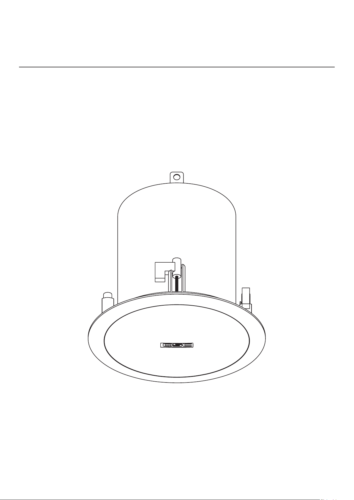
AcousticCoverage (AC)
User Manual
Model AC-C2T
TD-001530-01
*TD-001530-01*
Page 2
EXPLANATION OF SYMBOLS
The term
The term
WARNING!
CAUTION!
indicates instructions regarding personal safety. Failure to follow these instructions could result in bodily injury or death.
indicates instructions that prevent damage to physical equipment. Failure to follow these instructions could cause damage to the
equipment that may not be covered under the warranty.
The term
The term
IMPORTANT!
NOTE
indicates instructions or information that are vital to the successful completion of the procedure.
is used to indicate additional useful information.
The lightning flash with arrowhead symbol in a triangle indicates that there is uninsulated dangerous voltage within the product's enclosure
that may cause electric shock to a person.
The exclamation point within a triangle indicates important safety, operating, and maintenance information.
IMPORTANT SAFETY INSTRUCTIONS
• Read these instructions and keep a copy for future reference. Strictly follow and heed all instructions and warnings. Install the loudspeaker only as
instructed.
• Do not use or submerge this loudspeaker in or near water or liquids.
• Clean only with a dry cloth. Do not use any aerosol spray, cleaner, disinfectant or fumigant on, near, or into the loudspeaker.
• Do not install the loudspeaker near any heat sources, such as radiators, heat registers, stoves, or other apparatus (including amplifiers).
• Do not use any attachments, accessories, mounts, or brackets that are not specified or approved by QSC, LLC.
• Refer all service to qualified personnel. Service is required if the mounting mechanism or loudspeaker have been damaged in any way, such as liquid
spilled into the loudspeaker; objects falling into it; exposure to rain or moisture; abnormal operation; or being dropped.
• Observe all applicable local codes. Consult a licensed professional engineer when devising an equipment installation to ensure compliance.
Maintenance and Repair
Advanced technology—e.g., the use of modern materials and powerful electronics—requires specially adapted maintenance and repair methods. To
avoid subsequent damage to the equipment, personal injury, and/or creation of additional safety hazards, have all maintenance or repair work on the
equipment performed only by a QSC authorized service station or an authorized QSC international distributor. QSC is not responsible for any injury,
harm, or related damages that arise from any failure of the customer, owner, or user of the equipment to facilitate those repairs.
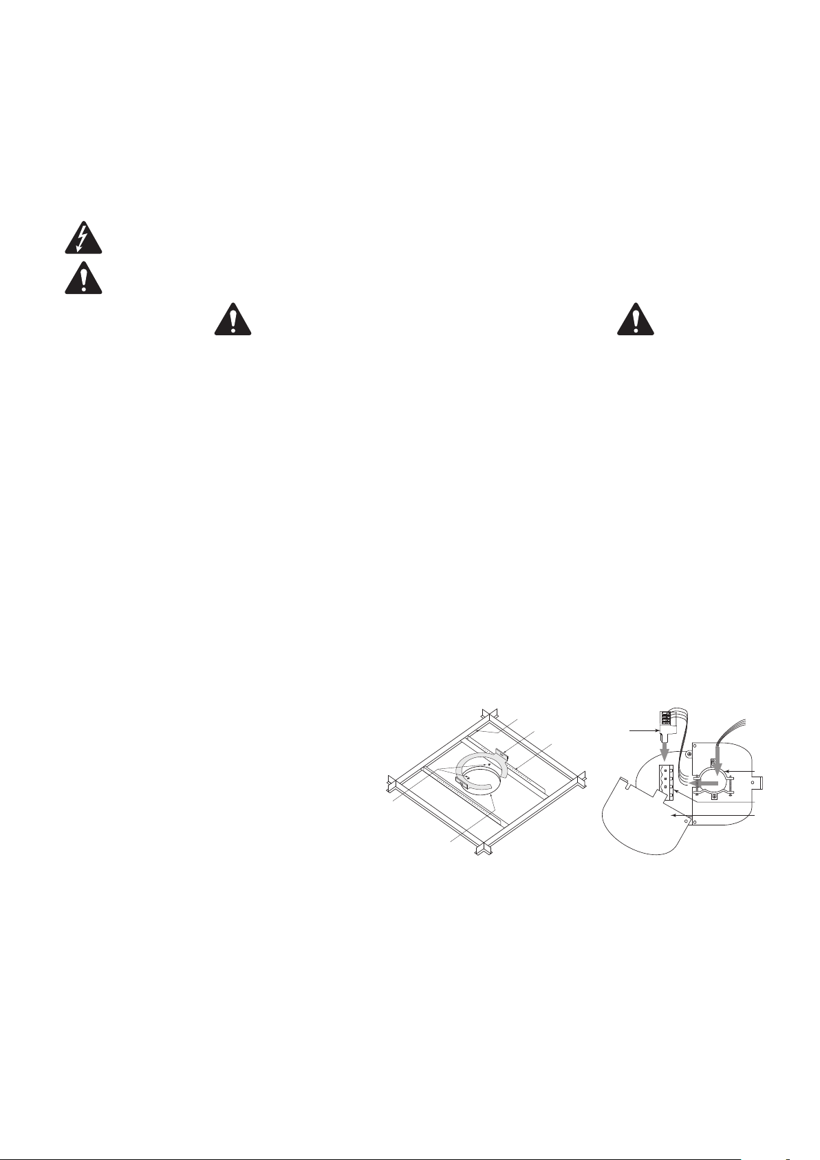
Prepare Ceiling
Refer to Figure 1.
1. Use the template provided to mark and cut a hole (1) in the
ceiling where the loudspeaker is to be installed. For a frameconstruction ceiling, skip to Wire the Loudspeakers.
2. Install two V-rails (2), one on each side of the hole, and
supported by the suspended-ceiling support rails (3).
3. Install the C-ring (3) over the hole, using the V-rails as support.
Make sure the clips on the C-ring are properly fitted over the
V-rail.
4. Use sheet-metal screws (5) to secure the C-ring to the V-rails.
5
1
— Figure 1 —–
3
4
2
2
— Figure 2 —–
1
3
4
Wire the Loudspeakers
Refer to Figure 2.
1. Pass the wires down through the conduit/stress-relief clamp. Leave enough slack wire for making connections. Carefully tighten the clamp over the
wires or conduit.
2. Wire the Euro-style plug (1) as shown in Figure 3.
3. Slide the cover (4) over the connector and secure with the Phillips screw.
TD-001530-01
2
Page 3

Seismic Safety
loudspeakers
[214.00 mm]
Ø7.15"
[201.05 mm]
[4.95 mm]
Refer to Figure 4.
1. Attach an appropriate safety line from the safety tab on the back
of the connector cover to an appropriate part of the structure.
WARNING!:
codes for seismic requirements.
Be sure to observe local building
Amp
From
source
To additional
Parallel Wiring Diagram
1
To additional
loudspeakers
Mount the Loudspeaker
Refer to Figure 5.
1. Make sure all of the dog-ears are up against the side of the metal
loudspeaker housing.
2. Slide the loudspeaker housing up through the hole into the
ceiling.
3. Use a Phillips screwdriver to tighten each of the four dog-ear
screws.
CAUTION!:
Do not overtighten the dog-ear screws!
— Figure 4 —–
4. Use a flat-tip screwdriver to set the transformer tap according to the design requirements.
5. Install the loudspeaker grille.
Specifications
Refer to Figure 6.
— Figure 3 —–
1
Dog-ears against loudspeaker
2
Turn the screw clockwise to engage
the dog-ear with the ceiling.
— Figure 5 —–
Name Specification
Transducer 2.75” treated paper cone
Rated noise power [continuous]
(1)
16 W
Nominal impedance 8 Ω
Transformer taps 1, 2, 4, 8, 16 W, and 8Ω bypass; 70 and 100 V
Effective frequency range
Rated coverage
(4)
Sensitivity
Maximum continuous SPL
Maximum peak SPL
(2)
(3)
70 Hz – 16 kHz
170 ° conical
83 dB
(5)
(5)
95 dB
101 dB
Net weight 1.86 kg [4.9 lb]
Shipping weight 5.8 kg [12.8 lb]
Product dimensions (diameter × height) Ø 214 mm × 201 mm [Ø 8.4” × 7.9”]
Shipping dimensions (H × W × D) 273.1 mm × 609.6 mm × 266.7 mm [10.75”
× 24” × 10.5”]
1 AES2-1984 noise signal for 2 hours; 8 ohm setting
2 Half-space, -10 dB from on-axis sensitivity
3 -6 dB from on-axis, 500 Hz – 5 kHz
4 Half-space, on-axis, 2.83 V rms, at 1 m
5 Calculated from rated noise voltage and sensitivity
8.43"
Ø6.93"
[176.00 mm]
[181.50 mm]
Ø5.59"
[142.00 mm]
7.5"
[191.10 mm]
7.9"
TD-001530-01
.2"
3
Page 4

Mailing Address:
QSC, LLC
1675 MacArthur Boulevard
Costa Mesa, CA 92626-1468 USA
Telephone Numbers:
Main Number: +1 (714) 754-6175
Sales & Marketing: +1 (714) 957-7100 or toll free (USA only) (800) 854-4079
Customer Service: +1 (714) 957-7150 or toll free (USA only) (800) 772-2834
Facsimile Numbers:
Sales & Marketing FAX: +1 (714) 754-6174
Customer Service FAX: +1 (714) 754-6173
World Wide Web:
www.qsc.com
E-mail:
info@qsc.com
service@qsc.com
tech_support@qsc.com
TD-001530-01
4
 Loading...