

QSC 3350 Brochure

SERIES THREE AMPLIFIERS FROM QSC
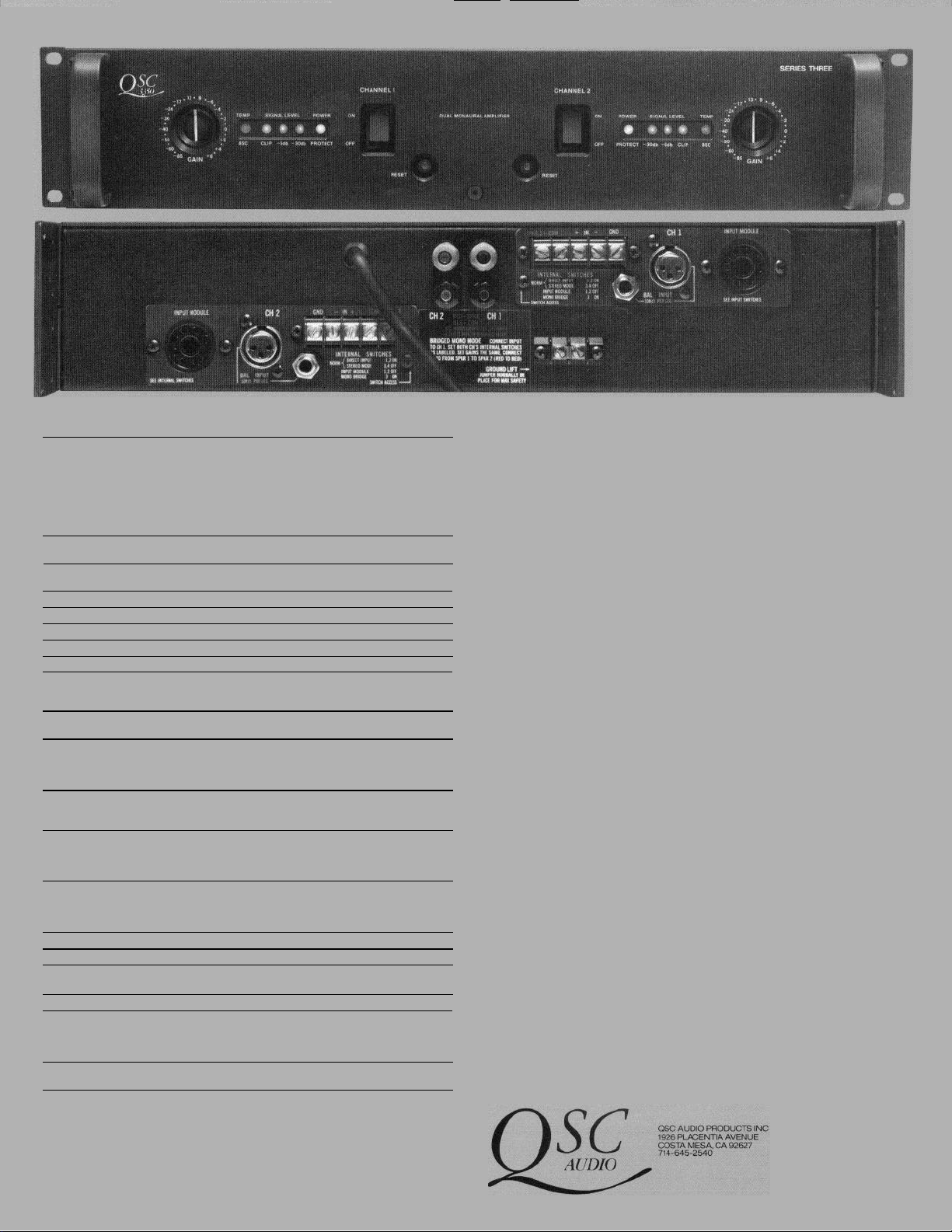
1MODEL 3350
The QSC Series Three Model 3350 is designed for high hensive interface panel is provided to assure proper
power audio applications where reference quality audio connection to any professional system.
reproduction must be combined with rugged low-profile Features:
design. Engineered specifically for recording studio\tour-
ing systems and engineered sound, this amp is well suited
for any high quality professional audio application.
Because of the high output power, this amplifier is an
excellent choice for driving medium sized full range ■ Front Removable Channel Modules
I
I
I
I
systems or mid-enclosures on multi-way systems. ■ Three Year Warranty
The amplifier is passively cooled and uses a high effi- ■ Precision 31 Step Detented Gain Controls
ciency output circuit to reduce operating temperatures. ■ Passive Cooling with High Efficiency Output Circuit
The dual mono configuration and front removable channel
I
I
module design are important features for those interested ■ Passive and Active Accessory Input Modules
in very high reliability and minimum down time. A compre-
■ Low Profile Chassis
■ 200 Watts Per Channel At 8 Ohms
■ 300 Watts Per Channel At 4 Ohms
■ Dual Mono Configuration
■ Comprehensive Interface Panel
■ Automatic Back-up in Bridged Mono Mode
I Is_.
I
L
I
I
I
/
I
I
!
I
I
I
i
I
I
1
I
SPECIFICATIONS
MODEL 3350
OUTPUT POWER (per channel)
Continuous Average Output Power Bridged-mono operation
both channels driven 16 ohms, 20–20kHz 0.1% THD 400
8 ohms, 20–20kHz 0.1% THD 200 1 kHz 1% THD 520
4 ohms, 20–20kHz 0.1% THD 300 1 kHz 1% THD 840
2 ohms, 1 kHz 1% THD 450
DISTORTION
FREQUENCY RESPONSE
DAMPING FACTOR
DYNAMIC HEADROOM
NOISE
SENSITIVITY
INPUT IMPEDANCE
CONTROLS
INDICATORS
(per channel)
CONNECTORS
(per channel)
COOLING
AMPLIFIER PROTECTION
LOAD PROTECTION
OUTPUT ClRCUIT TYPE
OUTPUT DEVICES (Total)
POWER SUPPLY
POWER REQUIREMENTS 120, 220, or 240V, 50–60Hz, 8A (Each channel)
DIMENSIONS Faceplate
WEIGHT Shipping (Ibs.)
Speciflcatlons subject
1 kHz 1% THD 260 8 ohms, 20–20kHz 0.1% THD 600
1 kHz 1% THD 420 4 ohms, 1 kHz 1% THD 900
THD - 20–20kHz from 250 milliwatts to rated power shall be less than 0.1%,
0.015% typical. SMPTE-IMD less than 0.020% 250 milliwatts to rated power
20–20kHz ±0.1dB
8–300kHz +0/-3dB
Greater than 200
3.0dB @ 4 ohms
-100dB 20–20kHz
1V RMS for rated power (8 ohms)
20K balanced or unbalanced
Front—Flush detented gain control • Recessed AC swltch and AC circuit breaker
for each channel
to
change
Rear— Mono-bridging and accessory module switches
Bi-color LED indicating DC power—OK/Protect mode • LED Clip lndicator
-30dB and -6dB signal level indicators. Flashing overtemp indicators
XLR, ¼" (ring, tip, sleeve) and 3 terminal barrier strip inputs wired in parallel
2 terminal barrier strip and 5-way binding post outputs wired in parallel
Octal Input sockets provided for input transformers or active accessories
Ground lift terminal block.
Passive – combined with high efficiency output stage for reduced operating
temperatures • Unique circuit configuration allows direct metal mounting of
output devices for reduced thermal stress from short-term peaks
Indefinite short circuit,* open circuit, over-temp, ultrasonic and rf protection
Stable into reactive and mismatched loads • Inputs protected from overload
All protection completely independent on each channel
*Output Averaging™ Short Circuit Protection (U.S. Pat. 4,321,554)
Individual channel Load Grounding™ output relays provide DC Fault, 3
second delayed turn on (transient protectlon), and excessive low frequency
protectlon • Instant turn-off, pop suppression and power interrupt protection
is also provided
Full complementary two-level high efficiency.
16
Two completely separate power supplies including AC switches and AC circuit
breakers; only AC cord is common
Depth (behind mtg, with
rear support)
Depth (chassis)
Net (lbs.)
without notice.
_ _
_
19"x35"
17.9"
15.9”
46
41
ARCHITECT’S AND
ENGINEER’S SPECIFICATIONS
The amplifier shall contain all solid-state circuitry, using complementary/silicon transistors and
integrated circuits. It shall be capable of operating from 120, 220 or 240V, 50-60Hz AC mains
with internally selectable jumpers.
The amplifier shall contain two fully independent channels, with separate AC switches, circuit
breakers, power transformers, and protective systems. Each channel shall have independent protective circuitry against open-circuit, short-circuit or mismatched loads; independent thermal
warning and shutdown circuits, and independent load protection circuits for turn on/off transients including momentary AC dropouts and DC faults within or preceding the amplifier. All protective circuits shall be self-resetting. The remaining channel shall continue to operate, in stereo
or bridged-mono mode, after failure of either channel.
Each channel of the amplifier shall be capable of meeting the following performance criteria,
with both channels driven simultaneously:
Output power into 8 ohms 200 watts, from 20-20kHz, with less than 0.1% distortion.
Output power into 4 ohms 300 watts, from 20-20kHz, with less than 0.1% distortion.
Output power into 2 ohms 450 watts, at 1kHz, with less than 1% distortion.
Frequency response shall be 20–20kHz with less than 0.1dB deviation.
The voltage gain shall be 32dB at full Gain.
The power gain shall be 63dB at full Gain.
The input sensitivity for rated 8-ohm power shall be 1V RMS.
Balanced bridging input circuitry shall be standard, and the amplifier shall meet all performance
criteria in the balanced or unbalanced mode.
Input impedance shall be 20k ohms balanced or unbalanced.
Noise level shall be at least 100dB below rated power, at full Gain.
IHF damping factor shall exceed 200.
The amplifier shall be passively cooled, with no fans or moving parts.
Each channel shall have the following controls functions, and connectors:
31-step Gain control, with 1dB steps over the highest 14dB of adjustment range, with accuracy
within 1dB;
Green/Red LED for power/protect indication;
Yellow LED signal presence indicators for outputs 6dB and 30dB below rated power;
Red LED indicator for any output clipping greater than 0.1%;
Flashing red LED indicator for heat sink temperatures within 10°C of thermal shutdown.
Balanced/Unbalanced input jacks of the ¼ inch ring-tip-sleeve, female XLR, and barrier strip
screw terminal type;
Speaker connections of the five-way binding post and barrier strip screw terminal type;
An octal socket with DC power for passive and active plug-in input accessory modules.
8-way microswitches for octal socket bypass, mono-bridged mode, cross-connection of chan-
nels and XLR input polarity
Each channel shall be front-removable with the amplifier mounted in a rack and without dis-
connecting the input/output cables. All active components, except AC power transformer, AC
switch, circuit breaker, and input/output connectors, shall be mounted on the removable channel
module. Module connectors shall be flexible to withstand shocks and vibration.
The amplifier chassis shall have a permanently attached AC cord, and a ground-lift jumper
which permits the separation of circuit and chassis grounds if required.
The chassis shall have front and rear 19” rack supports, and shall occupy two rackspaces (3.5”)
Chassis depth, including rear supports, shall be 17.9 inches.
Weight shall be 42 Ibs.
The power amplifier shall be the QSC Audio Products Model 3350.
 Loading...