

Page 1

Central Management System
User Manual (Version: 1.0.1)
© 2013. QNAP Systems, Inc. All Rights Reserved.
VioStor CMS
Page 2

Thank you for choosing the QNAP products! This user manual will introduce you how to use
the VioStor Central Management System (CMS) server and client applications. Please
follow the instructions in this user manual and start to enjoy the powerful VioStor CMS
system.
Note:
This user manual contains the instructions for using the QNAP CMS server and software.
Some features are only available on specific models. The model you purchased may not
support these features.
The CMS hardware/server is hereafter referred to as the CMS Server, and the central
management software is referred to as the CMS Client.
This user manual (version 1.0.1) is only applicable for the CMS Client version 1.0.1.
In order to support the full functions of CMS Client version 1.0.1, please use the VioStor
NVR firmware version 4.1.0 or later versions.
Legal Notice
All the features, functionality, and other product specifications are subject to change
without prior notice or obligation. Information contained herein is subject to change
without notice.
QNAP and the QNAP logo are trademarks of QNAP Systems, Inc. All other brands and
product names referred to are trademarks of their respective holders. Further, the ® or ™
symbols are not used in the text.
Limited Warranty
In no event shall the liability of QNAP Systems, Inc. (QNAP) exceed the price paid for the
product from direct, indirect, special, incidental, or consequential damages resulting from
the use of the product, its accompanying software, or its documentation. QNAP makes no
warranty or representation, expressed, implied, or statutory, with respect to its products or
the contents or use of this documentation and all accompanying software, and specifically
disclaims its quality, performance, merchantability, or fitness for any particular purpose.
QNAP reserves the right to revise or update its products, software, or documentation
without obligation to notify any individual or entity.
2
Page 3

Note:
Back up the system periodically to avoid any potential data loss. QNAP disclaims any
responsibility of all sorts of data loss or recovery.
Should you return any components of the product package for refund or maintenance,
make sure they are carefully packed for shipping. Any form of damages due to improper
packaging will not be compensated.
Please read the safety warnings and user manual carefully before using this product.
This product can only be used with the power supply provided by the manufacturer.
Please contact qualified technicians for any technical enquires. Do not repair this
product by yourself to avoid any voltage danger and other risks caused by opening this
product cover.
To avoid fire or electric shock, do not use this product in rain or humid environment.
Do not place any objects on this product.
3
Page 4

Regulatory Notice
FCC Notice
The QNAP products comply with different FCC compliance classes. Please refer the
Appendix for details. Once the class of the device is determined, refer to the following
corresponding statement.
=======================================================
FCC Class B Notice
This device complies with Part 15 of the FCC Rules. Operation is subject to the following two
conditions:
1. This device may not cause harmful interference.
2. This device must accept any interference received, including interference that may
cause undesired operation.
Note: This equipment has been tested and found to comply with the limits for a Class B
digital device, pursuant to Part 15 of the FCC Rules. These limits are designed to provide
reasonable protection against harmful interference in a residential installation. This
equipment generates, uses, and can radiate radio frequency energy and, if not installed
and used in accordance with the instructions, may cause harmful interference to radio
communications. However, there is no guarantee that interference will not occur in a
particular installation. If this equipment does cause harmful interference to radio or
television reception, which can be determined by turning the equipment off and on, the
user is encouraged to try to correct the interference by one or more of the following
measures:
• Reorient or relocate the receiving antenna.
• Increase the separation between the equipment and receiver.
• Connect the equipment into an outlet on a circuit different from that to which the
receiver is connected.
• Consult the dealer or an experienced radio/television technician for help.
Modifications: Any modifications made to this device not approved by QNAP Systems, Inc.
4
Page 5

may void the authority granted to the user by the FCC to operate this equipment.
CE NOTICE
Class B only.
5
Page 6

Symbols in this document
Warning
This icon indicates the instructions must be strictly followed.
Failure to do so could result in injury to human body or death.
Caution
This icon indicates the action may lead to disk clearance or loss OR
failure to follow the instructions could result in data damage, disk
damage, or product damage.
Important
This icon indicates the information provided is important or related
to legal regulations.
6
Page 7

Table of Contents
TABLE OF CONTENTS ...................................................................................................................................... 7
SAFETY WARNING .......................................................................................................................................... 10
CHAPTER 1 INTRODUCTION .................................................................................................................. 11
1.1 OVERVIEW ............................................................................................................................................ 11
1.2 HARDWARE ILLUSTRATION ................................................................................................................... 12
1.3 HARDWARE SPECIFICATION .................................................................................................................. 14
CHAPTER 2 INSTALLING CMS SERVER .............................................................................................. 16
2.1 BROWSING CD-ROM ........................................................................................................................... 16
2.2 HARD DISK DRIVE COMPATIBILITY LIST .............................................................................................. 17
2.3 IP CAMERA COMPATIBILITY LIST .......................................................................................................... 17
2.4 CHECKING SYSTEM STATUS .................................................................................................................. 18
2.5 SYSTEM CONFIGURATION ..................................................................................................................... 20
CHAPTER 3 INSTALLING CMS CLIENT ............................................................................................... 25
3.1 SUGGESTED PC SPECIFICATION FOR CMS CLIENT ............................................................................... 25
3.2 INSTALLING CMS CLIENT .................................................................................................................... 26
3.3 CONNECTING CMS CLIENT TO CMS SERVER ....................................................................................... 28
3.4 QUICK CONFIGURATION WIZARD ......................................................................................................... 30
3.5 CONFIGURING CMS CLIENT ................................................................................................................. 37
3.6 LICENSE................................................................................................................................................ 40
3.7 ACTIVATING LICENSE ONLINE .............................................................................................................. 41
3.7.1 ACTIVATING LICENSE OFFLINE.......................................................................................................... 42
3.7.2 TRANSFERRING/DELETING AUTHORIZATION ..................................................................................... 46
3.8 SERVER ................................................................................................................................................. 50
3.8.1 ADDING NVR ..................................................................................................................................... 51
3.8.2 DELETING/EDITING NVR ................................................................................................................... 55
3.8.3 ADDING/REMOVING CAMERA ............................................................................................................. 56
3.8.4 FIRMWARE UPDATE ................................................................ ................................ ............................ 56
3.8.5 TCP/IP CONFIGURATION ................................................................................................................... 58
3.8.6 SYSTEM TIME ..................................................................................................................................... 63
3.8.7 ALERT NOTIFICATION ........................................................................................................................ 63
3.8.8 SMSC SETTINGS ................................................................................................................................ 64
3.9 CAMERA ............................................................................................................................................... 66
3.10 EVENT MANAGEMENT .......................................................................................................................... 69
3.11 VIEW ................................................................................................ ................................ .................... 71
3.12 E-MAP .................................................................................................................................................. 77
7
Page 8

3.12.1 ADDING E-MAP .............................................................................................................................. 80
3.12.2 EDITING AN E-MAP NAME ............................................................................................................. 83
3.12.3 DELETING E-MAP .......................................................................................................................... 83
3.12.4 EDITING IP CAMERA ON E-MAP .................................................................................................... 84
3.13 USER MANAGEMENT ............................................................................................................................ 85
3.13.1 ROLE MANAGEMENT ..................................................................................................................... 86
3.13.2 GROUP MANAGEMENT ................................................................................................................. 100
3.13.3 USER LIST .................................................................................................................................... 106
3.14 CMS SERVER SETTINGS ..................................................................................................................... 107
3.14.1 DOMAIN SECURITY ................................................................................................ ...................... 107
3.15 LIVE VIEW .......................................................................................................................................... 111
3.15.1 LIVE VIEW PAGE .......................................................................................................................... 117
3.15.2 BOOKMARK .................................................................................................................................. 120
3.15.3 PTZ CAMERA CONTROL .............................................................................................................. 123
3.15.4 AUTO CRUISING ........................................................................................................................... 124
3.15.5 ALARM MODE (ALARM LIST & EVENT LOGS) ............................................................................. 128
3.15.6 E-MAP .......................................................................................................................................... 130
3.15.7 MULTI-MONITOR MODE .............................................................................................................. 133
3.16 PLAYBACK .......................................................................................................................................... 135
3.16.1 VIDEO PLAYBACK PAGE ............................................................................................................... 135
3.16.2 MULTI-VIEW PLAYBACK ............................................................................................................... 143
3.16.3 EXPORTING VIDEO FILE ................................................................................................ .............. 146
CHAPTER 4 SERVER LOG ...................................................................................................................... 149
4.1 EVENT LOG ........................................................................................................................................ 149
4.2 SERVICE LOG ...................................................................................................................................... 150
4.3 SYSTEM LOG ................................................................................................................................ ...... 151
4.4 NVR EVENT LOG ............................................................................................................................... 152
4.5 ONLINE USER ..................................................................................................................................... 153
CHAPTER 5 CMS SERVER MANAGEMENT ....................................................................................... 154
5.1 GENERAL SETTING ............................................................................................................................. 154
5.1.1 SYSTEM ADMINISTRATION ................................................................................................................ 154
5.1.2 DATE AND TIME ................................................................................................................................ 154
5.1.3 DAYLIGHT SAVING TIME................................................................................................................... 156
5.1.4 LANGUAGE ....................................................................................................................................... 157
5.1.5 PASSWORD STRENGTH ...................................................................................................................... 157
5.2 NETWORK SETTING ............................................................................................................................ 158
5.2.1 TCP/IP ............................................................................................................................................. 158
8
Page 9

5.2.2 DDNS ............................................................................................................................................... 160
5.2.3 IPV6 ................................................................................................................................................. 162
5.3 POWER MANAGEMENT ....................................................................................................................... 164
5.4 BACKUP/RESTORE SETTINGS .............................................................................................................. 165
5.5 SYSTEM LOG ................................................................................................................................ ...... 166
5.5.1 SYSTEM EVENT LOG ......................................................................................................................... 166
5.5.2 SYSTEM CONNECTION LOG .............................................................................................................. 166
5.5.3 ON-LINE USER .................................................................................................................................. 167
5.6 FIRMWARE UPDATE ............................................................................................................................ 167
5.6.1 UPDATE FIRMWARE BY WEB ADMINISTRATION PAGE ...................................................................... 167
5.6.2 UPDATE FIRMWARE BY QNAP FINDER ............................................................................................ 169
5.7 RESTORING TO FACTORY DEFAULT ..................................................................................................... 171
5.8 DISK MANAGEMENT ........................................................................................................................... 171
5.8.1 VOLUME MANAGEMENT ................................................................................................................... 171
5.8.2 RAID MANAGEMENT ....................................................................................................................... 174
5.8.3 HDD SMART .................................................................................................................................. 176
5.8.4 ENCRYPTED FILE SYSTEM ................................................................................................................ 176
5.9 SYSTEM STATUS ................................................................................................................................. 179
5.9.1 SYSTEM INFORMATION ..................................................................................................................... 179
5.9.2 RESOURCE MONITOR ....................................................................................................................... 179
CHAPTER 6 TROUBLESHOOTING ...................................................................................................... 183
TECHNICAL SUPPORT ................................ ................................ ................................................................ . 191
GNU - GENERAL PUBLIC LICENSE .......................................................................................................... 192
9
Page 10
Safety Warning
1. This product can operate normally in the temperature of 0ºC–40ºC and relative
humidity of 0%–90%. Please make sure the environment is well-ventilated.
2. The power cord and devices connected to this product must provide correct supply
voltage.
3. Do not place this product in direct sunlight or near chemicals. Make sure the
temperature and humidity of the environment are in optimized level.
4. Unplug the power cord and all connected cables before cleaning. Wipe this product
with a wet towel. Do not use chemical or aerosol to clean this product.
5. Do not place any objects on this product for the server's normal operation and to avoid
overheat.
6. Use the flat head screws in the product package to lock the hard disks in this product
when installing hard disks for proper operation.
7. Do not place this product near any liquid.
8. Do not place this product on any uneven surface to avoid falling off and damage.
9. Make sure the voltage is correct in your location when using this product. If you are not
sure about the voltage, please contact the distributor or the local power supply
company.
10. Do not place any object on the power cord.
11. Do not attempt to repair this product in any occasions. Improper disassembly of the
product may expose you to electric shock or other risks. For any enquiries, please
contact the distributor.
12. The chassis models should only be installed in the server room and maintained by the
authorized server manager or IT administrator. The server room is locked by key or
keycard access and only certified staff is allowed to enter the server room.
Warning:
Danger of explosion if battery is incorrectly replaced. Replace only with the same or
equivalent type recommended by the manufacturer. Dispose of used batteries
according to the manufacturer's instructions.
Do NOT touch the fan inside the system to avoid serious injuries.
10
Page 11

Chapter 1 Introduction
1.1 Overview
The QNAP Central Management System (CMS) is a high performance turnkey solution for
large-scale and multiple-site surveillance projects. The CMS Client is a software utility
designed to manage the QNAP VioStor network video recorders (NVR) and perform live
video monitoring, recording, and playback. The CMS Server supports up to a maximum of
128 multi-server monitoring. Users can monitor up to a maximum of 1024 IP cameras, up
to a maximum of 64 channels per screen. Concurrent independent playbacks and display
controls in four screens are also supported. The CMS Server has the highest compatibility
with the QNAP VioStor NVR series and also supports a variety of brand name IP cameras.
For detailed compatibility list, please refer to:
http://www.qnapsecurity.com/pro_compatibility_camera.asp
11
Page 12
1.2 Hardware Illustration
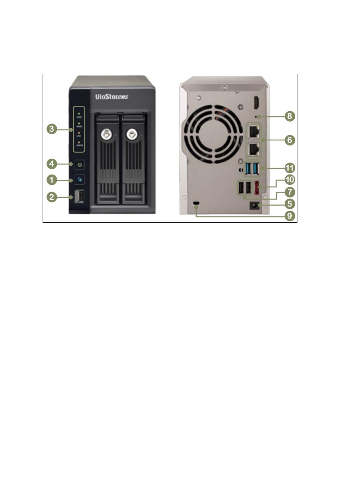
CMS-2000:
1. One Touch Copy button
2. USB 2.0 (reserved)
3. LED indicators: HDD1, HDD2, LAN, eSATA
4. Power button
5. Power connector
6. Gigabit LAN x 2
7. USB 2.0 x 2 (reserved)
8. Password & network settings reset button
9. K-Lock security slot
10. eSATA(reserved)
11. USB 3.0 x 2 (reserved)
12
Page 13
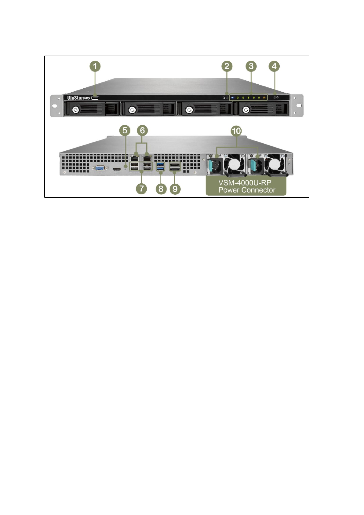
CMS-4000U-RP:
1. USB 2.0 (reserved)
2. One Touch Copy button
3. LED indicators: HDD1-4, LAN, eSATA
4. Power button
5. Password & network settings reset button
6. Gigabit LAN x 2
7. USB 2.0 x 4 (reserved)
8. USB 3.0 x 2 (reserved)
9. eSATA (reserved)
10. Power Connector
13
Page 14

1.3 Hardware Specification
Model Name
CMS-2000
Number of License
Base: 64, Maximum:1,024
HDD
2 x 3.5” or 2.5” SATA (Hot-swappable and lockable tray)
CPU
Intel 2.13GHz dual-core processor
RAM
1GB
Operating System
Linux Embedded
Ethernet Port
Gigabit Rj-45 Ethernet port x 2
Dimensions
150 (H) x 102 (W) x 216 (D) mm
5.91 (H) x 4.02 (W) x 8.5 (D) inch
Net Weight
1.74 Kg (3.84 lb)
Gross weight
2.92 Kg (6.44 lb)
Temperature
0-40 °C
Relative Humidity
0-95 % R.H.
Power Supply
Input: 100-240V AC, 50/60 Hz
Output: 90W
CMS-2000:
14
Page 15

CMS-4000U-RP:
Model Name
CMS-4000U-RP
Number of License
Base: 64, Maximum:1,024
HDD
4 x 3.5” or 2.5” SATA (Hot-swappable and lockable tray)
CPU
Intel 2.13GHz dual-core processor
RAM
1GB
Operating System
Linux Embedded
Ethernet Port
Gigabit Rj-45 Ethernet port x 2
Dimensions
44 (H) x 439 (W) x 499 (D) mm
1.73 (H) x 17.28 (W) x 19.65 (D) inch
Net Weight
7.63 Kg (16.82 lb)
Gross weight
9.55 Kg (21.05 lb)
Temperature
0-40 °C
Relative Humidity
0-95 % R.H.
Power Supply
Input: 100-240V AC, 50/60 Hz
Output: Redundant 250W
15
Page 16
Chapter 2 Installing CMS Server
For details on product hardware installation, please refer to the “Quick Installation Guide”
(QIG) in the product package.
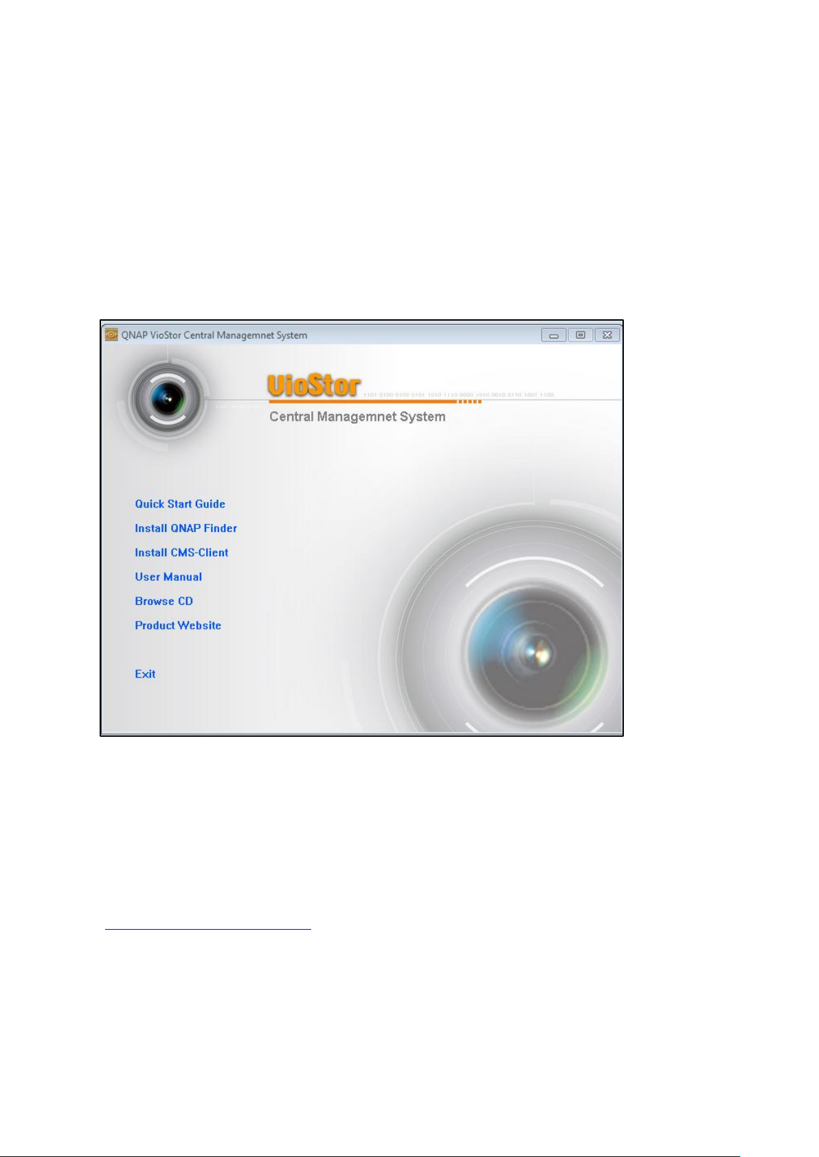
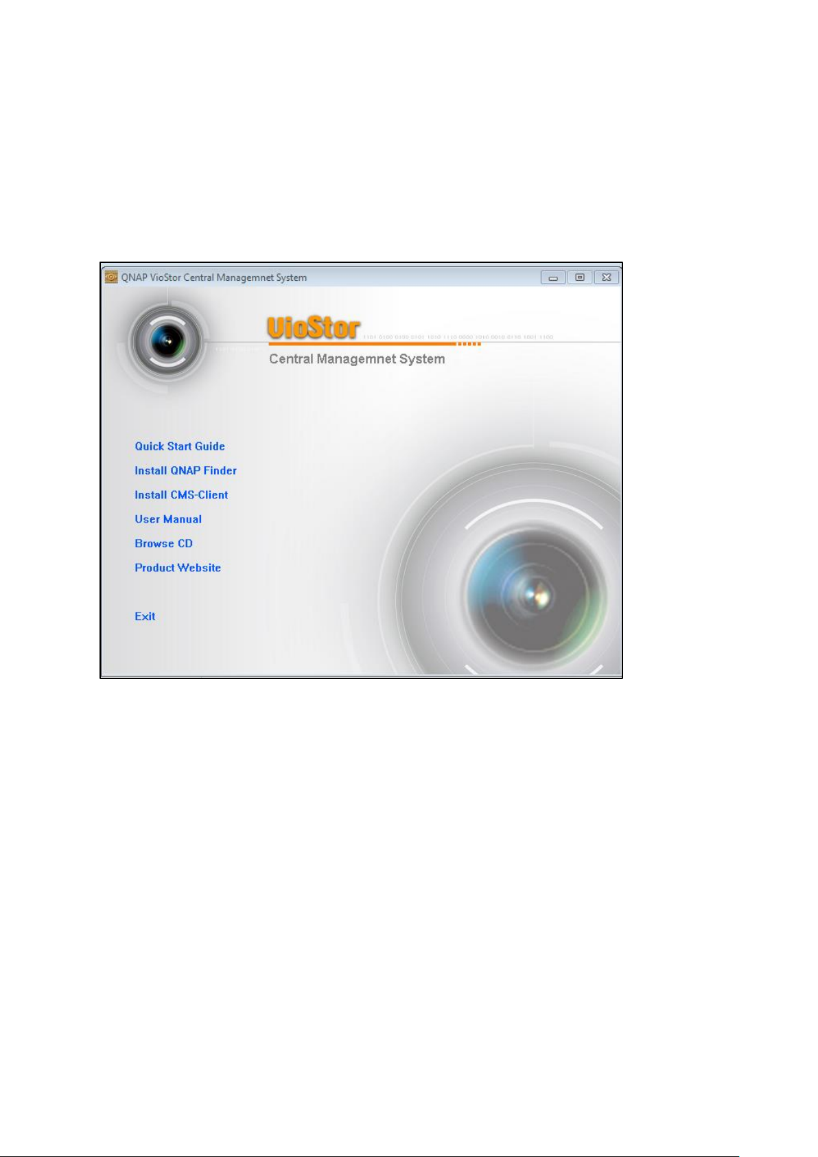
2.1 Browsing CD-ROM
The CMS installation CD-ROM contains the Quick Start Guide, CMS Client, QNAP Finder, and
the user manual.
Browse the CD-ROM and access the following contents:
Finder: The setup program of the QNAP Finder (for Windows OS).
CMS Client: The main program of the central management and monitoring system.
Manual: The user manual of the QNAP VioStor CMS.
The above contents can also be downloaded at the QNAP Security website
(http://www.qnapsecurity.com).
16
Page 17

2.2 Hard Disk Drive Compatibility List
This product works with popular brands of 2.5-inch and 3.5-inch SATA hard disk drives.
For hard disk compatibility list, please visit the QNAP Security website:
http://www.qnapsecurity.com/pro_compatibility.asp
Note: QNAP disclaims any responsibility for product damage/malfunction or data
loss/recovery due to misuse or improper installation of hard disks in any occasions for any
reasons.
2.3 IP Camera Compatibility List
For information on supported IP Camera models, please visit the QNAP Security website:
http://www.qnapsecurity.com/pro_compatibility_camera.asp
17
Page 18

2.4 Checking System Status
LED
Color
LED Status
Description
System
Status
Red/
Green
Flashes green
and red
alternately
every 0.5 sec
1) A hard drive on the system is being
formatted/initialized.
2) The system firmware is being updated.
3) RAID rebuilding is in process.
4) Online RAID Capacity Expansion is in
process.
5) Online RAID Level Migration is in process.
Red
1) A hard drive is invalid.
2) The disk volume has reached its full
capacity.
3) The disk volume is going to be full.
4) The system fan is out of function.
5) An error occurs when accessing
(read/write) the disk data.
6) A bad sector is detected on the hard drive
7) The system is in degraded read-only mode
(2 member drives fail in a RAID 5 or RAID
6 configuration, the disk data can still be
read).
8) (Hardware self-test error).
Flashes red
every 0.5 sec
The system is in degraded mode (one member
drive fails in RAID 1, RAID 5 or RAID 6
configuration).
Flashes green
every 0.5 sec
1) The system is starting up.
2) The system is not configured.
3) A hard drive is not formatted.
Green
The system is ready.
Off
All the hard drives on the system are in
standby mode.
LAN
Orange
Orange
The system is connected to the network.
Flashes
orange
The system is being accessed from the
network.
HDD (Hard
Drive)
Red/
Green
Flashes red
The hard drive data is being accessed and a
read/write error occurs during the process.
Red
A hard drive read/write error occurs.
Flashes green
The hard drive data is being accessed.
Green
The hard drive can be accessed.
LED Display & System Status Overview
18
Page 19

USB
Blue
Flashes blue
every 0.5 sec
1) A USB device is detected.
2) A USB device is being removed from the
system.
3) The USB device connected to the front
USB port of the system is being accessed.
4) The system data is being copied to the
external USB device.
Blue
The USB device connected to the front USB
port of the system is ready.
Off
1) No USB is detected.
2) The system has finished copying the data
to the USB device connected to the front
USB port of the system.
eSATA†
Orange
Flashes
The eSATA device is being accessed.
Beep sound
No. of Times
Description
Short beep (0.5 sec)
1
1) The system is starting up.
2) The system is being shut down (software
shutdown).
3) The reset button is pressed.
4) The system firmware has been updated.
Short beep (0.5 sec)
3
The system data cannot be copied to the
external device by pressing the auto-backup
button.
Short beep (0.5 sec),
long beep (1.5 sec)
3, every 5 min
The system fan is out of function.
Long beep (1.5 sec)
2
1) The disk volume is going to be full.
2) The disk volume has reached its full
capacity.
3) The hard drives on the system are in
degraded mode.
4) Hard disk rebuilding process starts.
1
1) The system is turned off by force shutdown
(hardware shutdown).
2) The system has been turned on
successfully and is ready.
Beep Alarm (beep alarm can be disabled in “System Tools” > “Hardware Settings”)
19
Page 20
2.5 System Configuration
Setting up the CMS Server
Follow the steps below to install the software of the CMS Server. The following example is
based on the Windows OS.
1. Install the QNAP Finder from the product CD.
2. Run the QNAP Finder. If the QNAP Finder is blocked by the firewall or anti-virus software,
unblock them.
20
Page 21
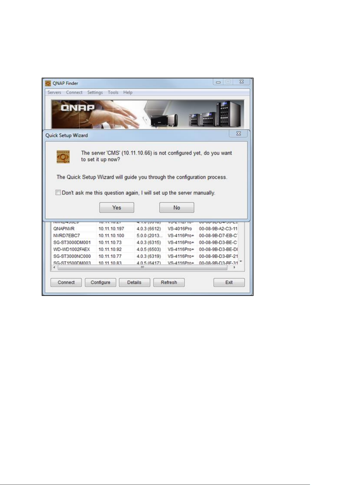
3. The QNAP Finder will scan for CMS Server(s) that have not been configured on the local
network. The CMS Server can be identified by the model number. Click “Yes” to start
setting up the CMS Server.
21
Page 22
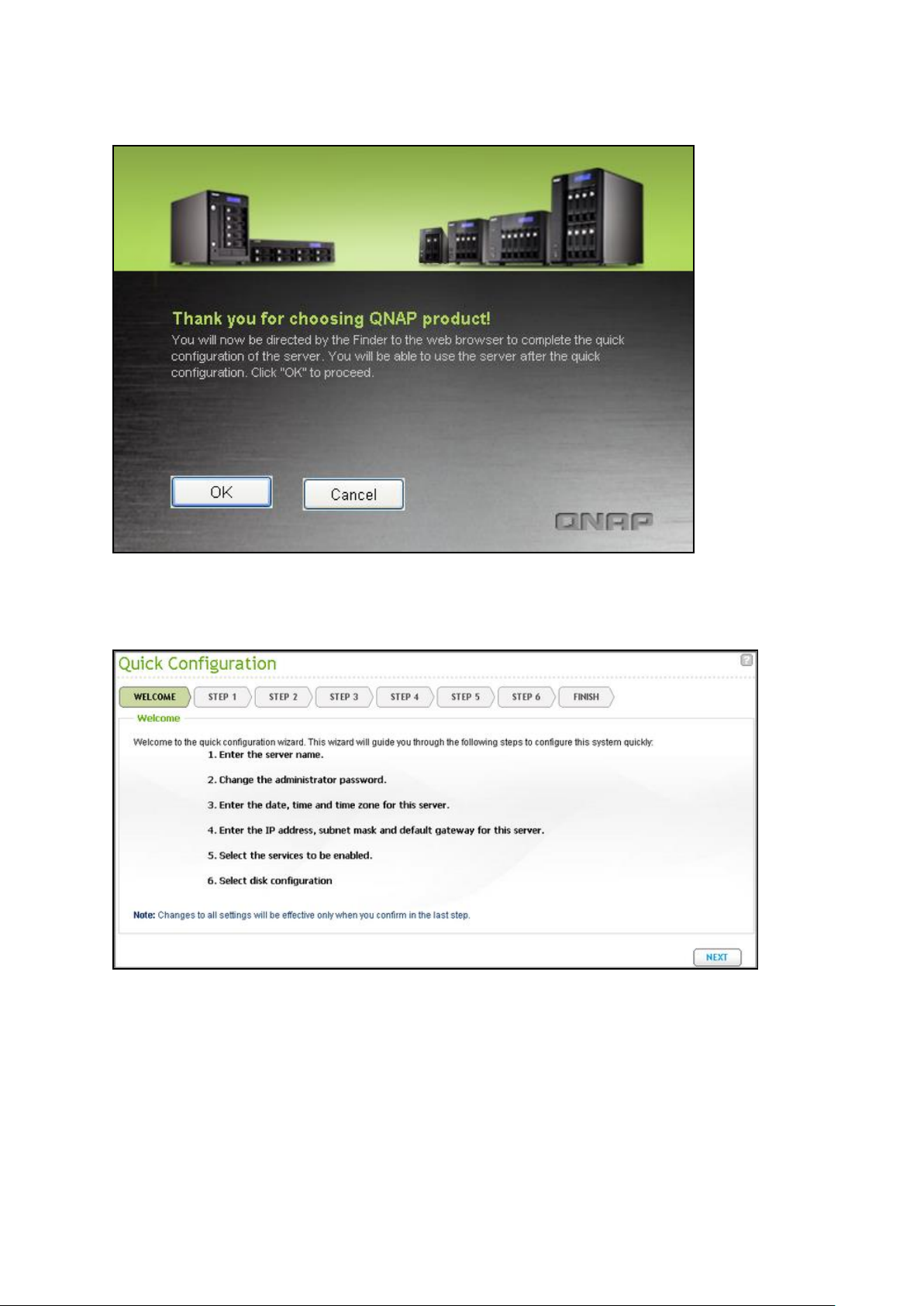
4. Click “OK” to proceed.
5. The default web browser will be opened. Follow the onscreen instructions to configure
the CMS Server.
22
Page 23
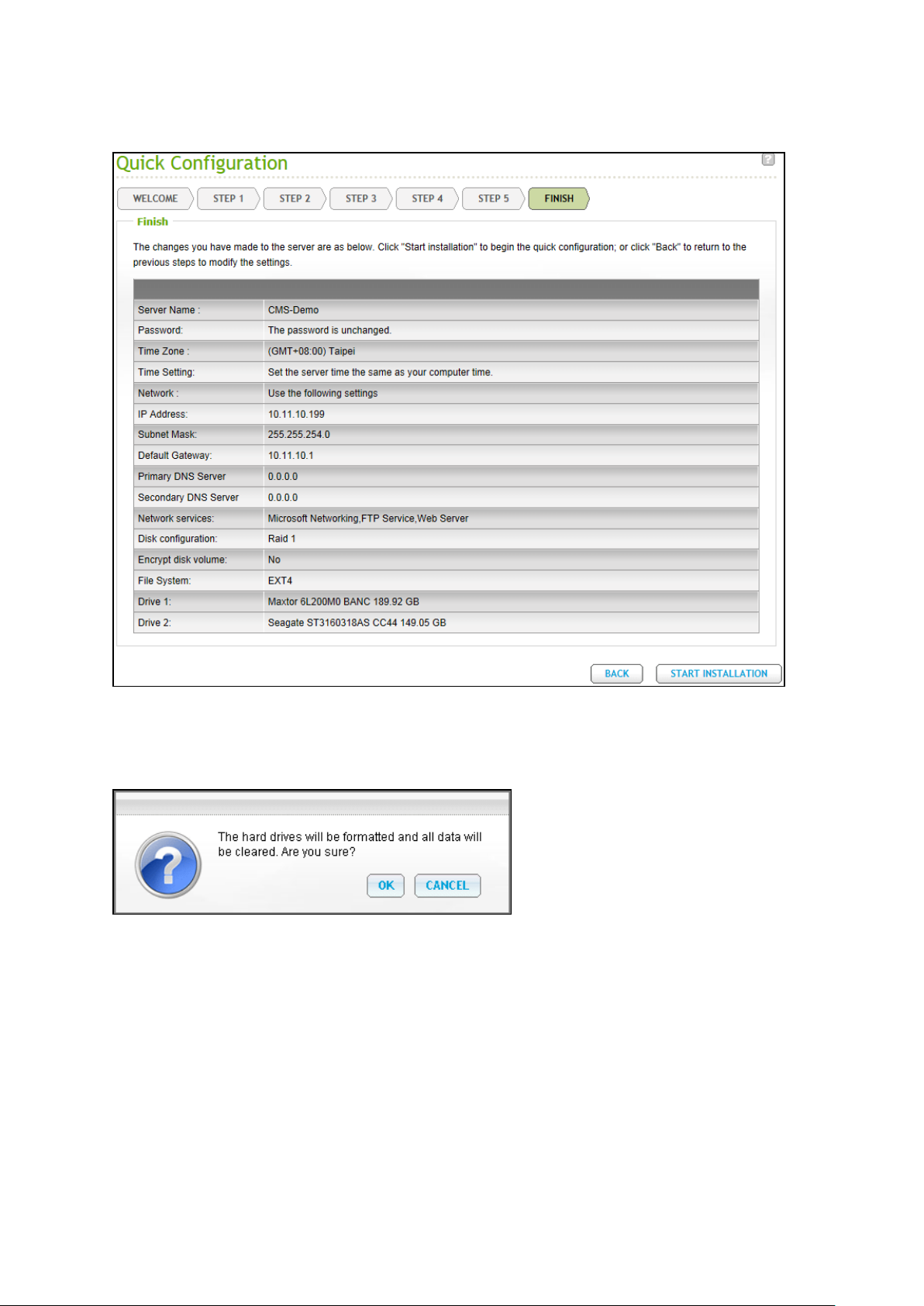
6. Click “START INSTALLATION” in the last step.
7. All the installed hard disk drives will be formatted, and all the data will be cleared.
Click “OK” to proceed.
23
Page 24
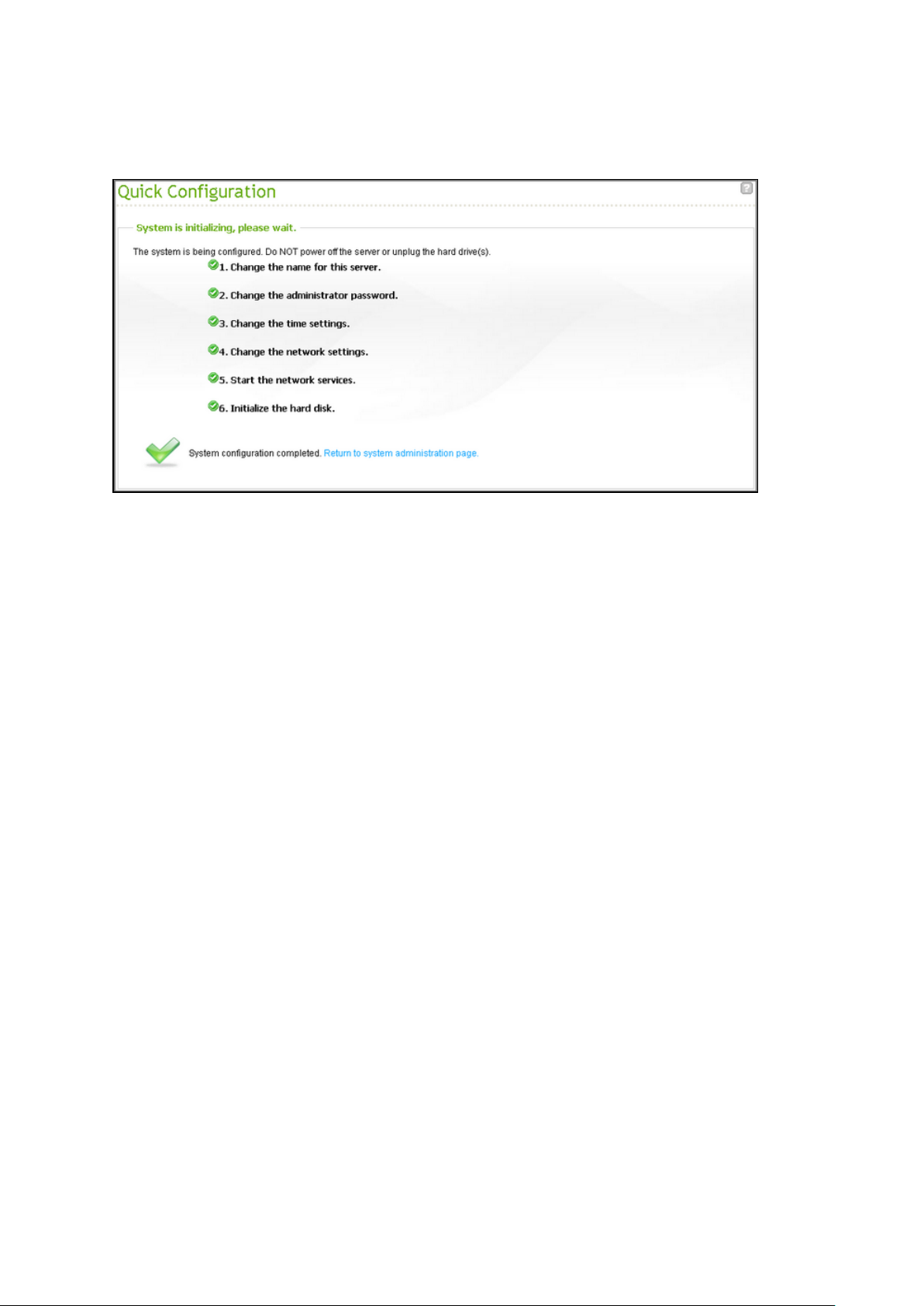
8. When finished, click “Return to system administration page” to complete the
initialization process for the CMS Server.
24
Page 25

Chapter 3 Installing CMS Client
CPU
Intel Sandy/Ivy bridge series
(To display full HD videos or monitor multiple cameras, i5/i7
or above is recommended.)
Memory
4GB or above
(To display HD videos or monitor multiple cameras, 6GB or
above is recommended.)
Operating System
Windows 7 (64-bit is recommended)
Network Interface
Gigabit Ethernet
Screen Resolution
1920 x 1080
Graphics Card
NVIDIA GeForce GT430 or above
ATI Radeon HD5700 or above
(For multi-monitor mode, NVIDIA GeForce GT640 or above
is recommended.)
After network settings of the CMS Server are configured, please connect the CMS Server to
the network and set up the CMS Client.
Important:Before using the CMS Client, make sure the hard disk drives on the CMS
Server have been properly installed and configured.
3.1 Suggested PC Specification for CMS Client
For optimal system performance, make sure the computer that the CMS Client runs on
fulfills at least the following requirements:
Note: The CMS Client supports Windows 7 64-bit OS and can utilize up to 4GB of RAM.
25
Page 26
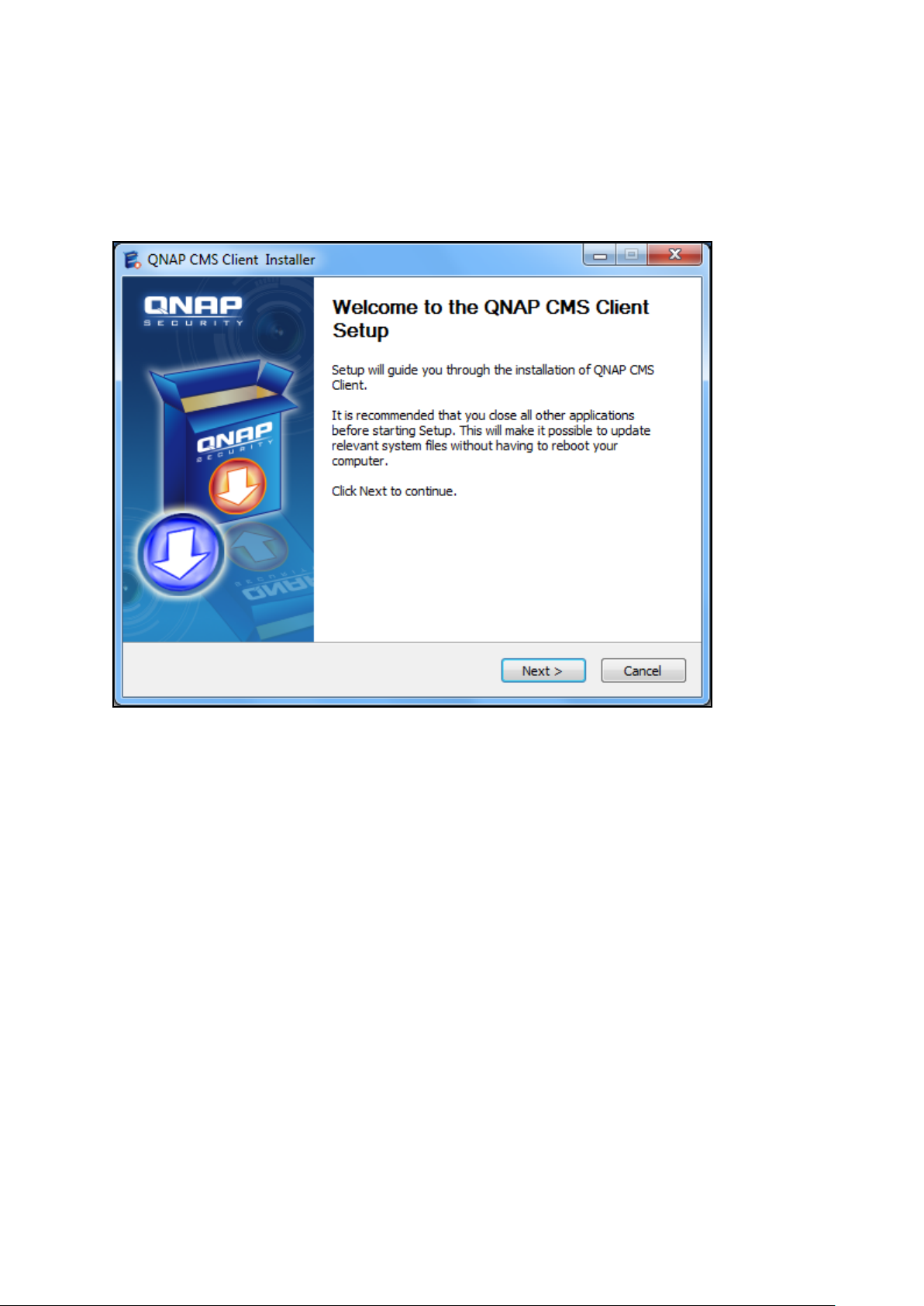
3.2 Installing CMS Client
Follow the steps below to install the CMS Client:
1. Run the CMS Client installer from the product CD and click “Next”.
26
Page 27
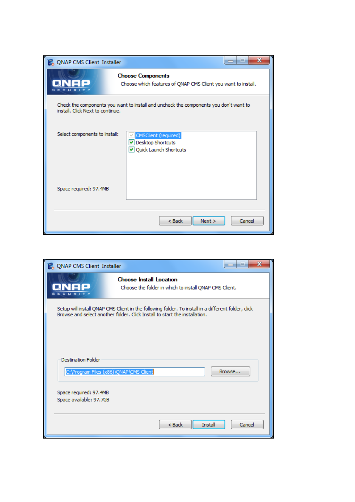
2. Choose the shortcuts to create and click “Next”.
3. Select the installation directory and click “Install”.
27
Page 28
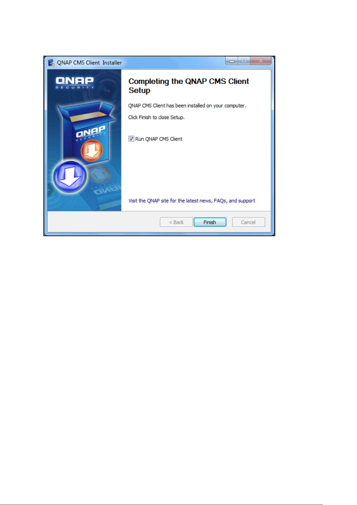
4. After finishing the installation process, click “Finish”.
3.3 Connecting CMS Client to CMS Server
Follow the steps below to connect the CMS Client to the CMS Server:
28
Page 29

1. Run the CMS Client. Enter the IP address of the CMS Server, the username, password
Select the CMS
Server and click
“Connect”.
and domain (please select the domain from the “Login to” field) and click “OK”. Or, click
“Auto Find” to search for CMS Servers on the local network. Double click a CMS Server
from the list to connect to it or click “Connect” to connect the CMS Server.
29
Page 30
2. Enter the administrator username and password to login and start using the CMS Client.
Default administrator credentials:
username: admin
Password: admin
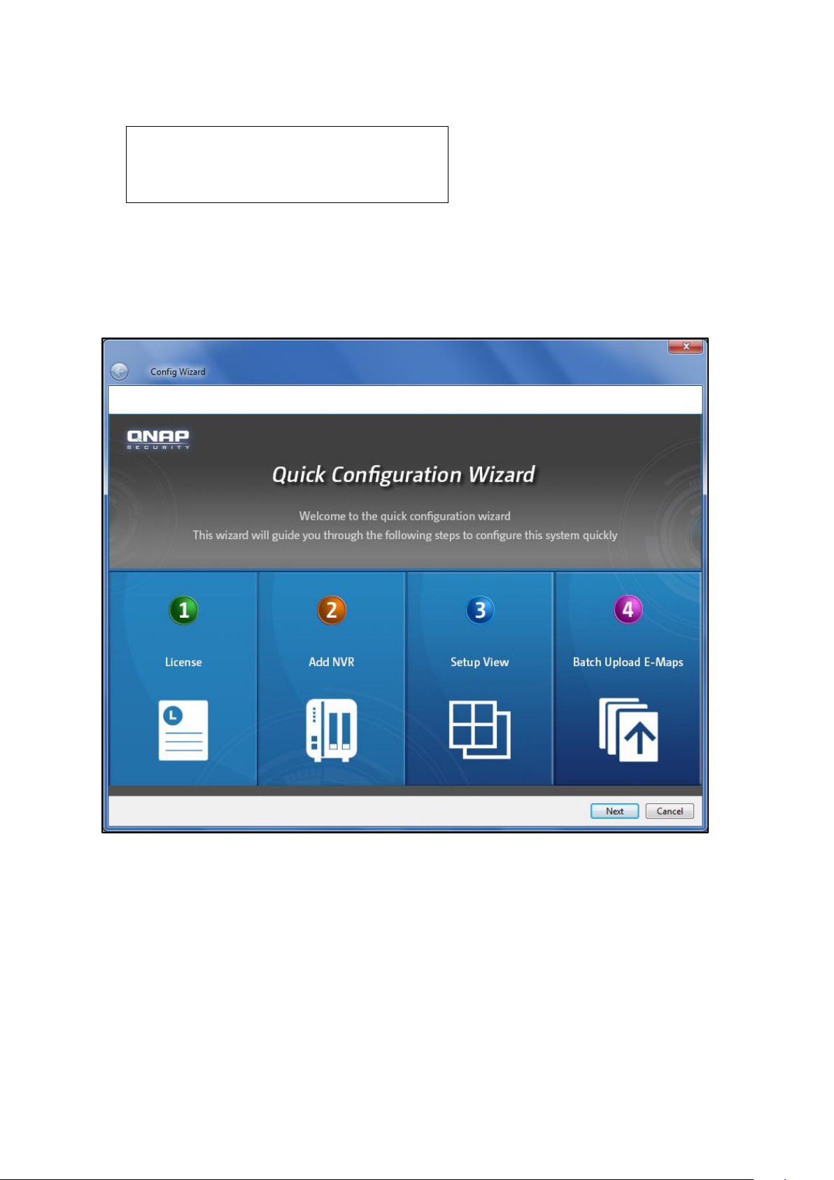
3.4 Quick Configuration Wizard
If this is the first time the CMS Client is configured, the Quick Configuration Wizard will start
automatically. Please follow the instructions to set up the CMS system.
30
Page 31

License Activation
Activate your license on this page. License activation is required before cameras can be
added. For details, please refer to Chapter 3.6.
31
Page 32

Adding NVR(s)
Click “Auto Detect” to search for the NVR(s) on the LAN automatically, or enter the NVR IP
address manually. Click > to move the NVR to be added to the box on the right and click
“Confirm” to add the NVR.
Tip: Use the “Shift” or “Ctrl” + up or down keys on the keyboard to select multiple NVR
servers.
For more details, please refer to Chapter 3.8.1.
32
Page 33

Set up Display Mode
The administrator can select the display mode and assign the channels manually to use the
sequential mode or have the all the channels assigned by the NVRs instead.
When “Sequential mode” is selected, cameras channels will be assigned sequentially to
each channel window in the display mode. If the number of cameras used in the sequential
mode is greater than the number of channels of the display mode, the extra channels will
be assigned from Channel 1 again. For instance, if 64 channels are assigned to a 6-channel
view, the seventh channel will be displayed on Channel 1 and the eighth channel will be
displayed on Channel 2, and so on and so forth. Please note that since a maximum of 10
channels can be assigned to one channel, please always select a display mode with a
maximum number of channels that is greater than the total number of selected channels
(ex. for 64 channels, please select the 8-channel view.)
When “Auto Assign by NVR” is selected, camera channels will be assigned based on NVRs.
For example, if 20 channels from NVR 1 and 32 channels from NVR 2 are selected for the
6-channel view, all 20 channels from NVR 1 will be first assigned from Channel 1 to Channel
6 sequentially (and the seventh channel from NVR 1 will be assigned to display on Channel
1 again and eighth on Channel 2.) All 32 channels from NVR 2 will then be assigned from
Channel 1 to Channel 6 after all cameras from NVR 1 are assigned.
Please note that in “Sequential mode”, channels assigned to a channel window will be
displayed and switched sequentially and automatically, while in “Auto Assign by NVR”,
channels need to be switched manually.
If both “Sequential mode” and “Auto Assign by NVR” are selected, all channels from the
same NVR will be assigned to and displayed on the selected display mode sequentially and
automatically. For instance, if 20 channels from NVR 1 and 32 channels from NVR 2 are
selected for the 6-channel view, all channels from NVR 1 will be assigned to and displayed
sequentially and automatically on the first page, and all 32 channels from NVR 2 will be
assigned to and displayed sequentially and automatically on the second page. To view the
channels from a different NVR, users are required to manually switch to the corresponding
pages.
33
Page 34

34
Page 35

35
Page 36

Uploading E-map(s)
Select the E-map files or directories on the right, click “Confirm” to upload the E-maps and
then click “Finish” to finish the wizard.
36
Page 37

3.5 Configuring CMS Client
To enter the system settings page on the CMS Client, login the live view page as an
administrator and then click .
37
Page 38

The system overview page will be opened. Select the overview period from the drop-down
menu on the top right corner. The system can display system details for up to seven days.
Click “Learn more” under each item to view the details.
The system overview page contains the following information:
Alarm: Alarm input, dynamic motion event information, and charts.
User account: user account related information, such as login failed, never logged in,
and the total number of user accounts.
NVR connection status: Information about the number of NVRs that have never been
disconnected and have been disconnected, and the total.
IP camera connection status: Information about the number of cameras that have
never been disconnected and have been disconnected, connection failure, and the
total.
NVR system status: Information about the number of hard disk failure, fan failure, and
the total.
Real-time status: Online users/total users, online NVRs/total NVRs, and online
cameras/total cameras.
Note:
Besides the real-time information, all other information provided is the records
from the previous seven days.
If a NVR is deleted, its records will also be permanently deleted and its logs will no
longer be available.
38
Page 39

The configuration settings are available on the left:
License
Server
Camera
Event management
View
E-map
User management
Server logs
CMS Server Settings
39
Page 40

3.6 License
Please activate your license on this page if you have not already done so using the Quick
Configuration Wizard. License activation is required before cameras can be added. A
64-channel license is provided for each CMS Server and you can choose to activate or
deactivate your license online of offline.
40
Page 41

3.7 Activating License Online
Please follow the steps below to activate your license online:
1. Click “Activate License Online”
2. Enter the product authorization key and click “Activate” and “Finish”.
41
Page 42

3. After the license is activated online, the license detail will appear.
3.7.1 Activating License Offline
If the Internet is unavailable, please follow the steps below to activate your license offline.
1. Click the “Activate License Offline” button. A prompt window will appear to remind you
to use another PC that can go online to bind the PAK and UDI. So, a physical permission
file can be generated to activate the CMS Client.
42
Page 43

2. Click “Offline Activation” after entering the License Store (http://license.qnap.com).
43
Page 44

3. After membership registration, please fill out the PAK provided, the device UDI and
verification code from the license activation page to download the physical permission file.
Tip: Use the “Copy UDI” function to copy UDI and paste in the field of QNAP license store.
44
Page 45

4. Upload the license file.
After the license is activated, its details will appear.
45
Page 46

3.7.2 Transferring/Deleting Authorization
To transfer and delete your license, please deactivate it first either online or offline.
Online License Deactivation: If Internet access is available for the CMS Server, please
click the license to be deactivated and then “Deactivate License Online“. The CMS
Server will connect to the License Store to deactivate the selected license. The system
will confirm with you about license deactivation. Please click “Yes“.
46
Page 47

The license will be deactivated and removed from the list.
Offline License Deactivation: If Internet connection is unavailable for the CMS Server,
please click “Deactivate License Offline“. The CMS Client will generate a deactivation ticket
(a physical file). Please upload this ticket to the License Store using another device that can
connect to the Internet. To deactivate the license offline, please follow the steps below:
1. Select a license to be deactivated, click “Yes” and a ticket will be generated.
47
Page 48

2. Go to the License Store using another computer that can connect to the Internet and
click “Offline Deactivation“.
48
Page 49

49
Page 50

3. Upload the deactivation ticket generated in Step 1, fill in the verification code and click
“Apply“.
3.8 Server
After license management (activation and deactivation), the next step is to add NVR
servers and cameras.
Add, delete, and edit any server types supported by the CMS on the “Server” page. You
can manage the cameras connected to the server.
50
Page 51

The CMS client can apply the same system time, alert notification and SMSC settings to a
number of NVRs (only limited to the same models) to save the system setup time.
3.8.1 Adding NVR
To add one or more NVR servers, click .
51
Page 52

You can use the auto-find function to search for the NVR server(s) on the LAN, or enter the
NVR IP address manually.
When adding more than one server, you can enter a pair of username and password and
apply to all of them. When the “Add all the cameras” option is checked, all the cameras
configured on the NVR will be added.
Note: When any pair of username and password for the multiple NVRs to be added is
incorrect, the server(s) will not be added and no warning message will appear.
If the subnet of an NVR is different from that of the CMS Client, use “Manual Add” and enter
the IP and port number of that NVR. Click “OK” to connect.
52
Page 53

53
Page 54

The NVR in another subnet will be added.
After adding all required NVR(s), click “OK” and the “Add Server in Progress” message box
will appear and the status will be shown in the box.
Click “Confirmation”. The system will add the servers one by one. There are four kinds of
status: Retrieving NVR Data, Add Channel (channel number) to CMS, Done and Connection
Error.
54
Page 55

Note: For the “Connection Error” error message, please check your user ID/password,
firewall and network settings.
3.8.2 Deleting/Editing NVR
To delete an NVR, select the NVR on the list and click . To edit the NVR details (server
name, IP address, port, user name, or password), select the NVR and click . Click “OK”
after all fields are completed.
Note: A NVR can only be edited and deleted by administrators of that NVR. Please be sure
to type in the administrator username and password in the Edit Server dialog window, or
details of cameras and their live view may not be displayed correctly.
55
Page 56

3.8.3 Adding/Removing Camera
Select an NVR from the list and a list of available cameras will be shown below. Use the left
and right arrows to add or remove the cameras to be controlled and monitored by the CMS
Client. After applying the settings, the number of cameras connected to the NVR will appear
next to the NVR name on the left list.
3.8.4 Firmware Update
Follow the steps below to update firmware:
1. Select the NVR for which to update the firmware and click “Update Firmware”.
56
Page 57

2. Browse and select the firmware image file (*.img) from the local computer.
57
Page 58

Tip: You can select to update the firmware of multiple NVR servers at the same time if they
are the same model.
3.8.5 TCP/IP Configuration
The CMS Server supports static IP assignment for all NVRs, and for each NVR, the number
of LAN ports can be different. Please note that DHCP is not supported.
58
Page 59

Configuring NVR with a Single LAN Port
If the NVR supports a single LAN port, select one of the following options to configure the
TCP/IP settings of the NVR.
Use static IP address: To assign a fixed IP to the NVR, enter the IP address, the subnet
mask, and the default gateway.
Primary DNS Server: Enter the IP address of the primary DNS server that provides the
DNS service for the NVR on the external network.
Secondary DNS Server: Enter the IP address of the secondary DNS server that provides
the DNS service for the NVR on the external network.
59
Page 60

Configuring NVR with Dual LAN Ports
If the NVR supports two LAN ports, select to use failover, load balancing, or standalone
setting. To use these features, make sure both LAN ports are connected to the network.
Failover (Default settings for dual LAN NVR models): Failover refers to the capability of
switching over the network transfer port to the redundant port automatically when the
primary one fails to avoid network disconnection. When the connection is resumed on
the primary network port, the network transfer will be switched over to that port
automatically.
Load balancing: Load balancing refers to the ability to spread network traffic between
two or more network interfaces to optimize the network transfer and enhance the
system performance.
60
Page 61

Note: To optimize the network transfer speed of the NVR in the load balancing mode, use
an Ethernet switch and enable 802.3ad (or link aggregation) on the switch ports that the
NVR’s Gigabit LAN ports are connected to.
61
Page 62

Standalone: Assign different IP settings for each network port. The NVR can be
accessed by different workgroups on two subnets. When load balancing is enabled,
failover will not work. The DHCP server can only be enabled for the primary network
port (LAN 1).
Use static IP address: To assign a fixed IP to the NVR, enter the IP address, the subnet
mask, and the default gateway.
Primary DNS Server: Enter the IP address of the primary DNS server that provides the
DNS service for the NVR on the external network.
Secondary DNS Server: Enter the IP address of the secondary DNS server that
provides the DNS service for the NVR on the external network.
62
Page 63

3.8.6 System Time
Set the date, time, and time zone. If the settings are incorrect, the following problems may
occur:
Incorrect time stamps on the video files.
Incorrect time stamps on the event logs.
Synchronize with an Internet time server automatically
Enable this option to update the date and time of the NVR automatically with an NTP
(Network Time Protocol) server Enter the IP address or the domain name of the NTP server
(for example, time.nist.gov or time.windows.com.)
3.8.7 Alert Notification
When a problem occurs (e.g. power outage or a hard disk drive is unplugged,) an alert
email will be sent to the specified recipients automatically.
63
Page 64

To configure this feature, please set the alert level and specify SMTP server address, SMTP
authorization credentials and email addresses of the recipients. To view the details of all the
errors and warnings, go to “Logs & Statistics” > “System Event Logs”.
Note: It is recommended to send a test email to make sure the mail server settings are
configured correctly.
3.8.8 SMSC Settings
Configure the SMSC (Short message service centre) settings to send the SMS text
messages to the particular mobile phone numbers when an event is detected by the NVR.
The default SMS service provider is Clickatell. Add an SMS service provider by selecting
“Add SMS Provider” from the drop-down menu.
64
Page 65

After “Add SMS service provider” is selected, enter the name of the SMS provider and the
URL template text.
Note:
Please always follow the standard published by the SMS service provider to configure
the SMS settings.
Please send a test SMS to verify that the settings are correct.
Go to “Camera Settings” > “Alarm Settings” > “Advanced Mode” to edit the SMS
settings, or select to use the “Traditional Mode” and configure the SMS settings on this
page.
It is recommended to send a test email to make sure the mail server settings are
configured correctly.
65
Page 66

3.9 Camera
Information of the cameras being controlled by the CMS is shown on this page. The
information shown on this page includes the camera name, the NVR that the camera
belongs to, IP address, model, and the live video. Recording settings and schedules of the
cameras can also be managed on this page.
Under the “Recording” tab, you can configure the video compression format, screen
resolution, frame rate, and video quality, and select to enable or disable audio recording
and manual recording for the configured channel.
66
Page 67

Video compression: Select the compression format of the recording files.
Resolution: Select the recording resolution of the camera. The higher the resolution, the
clearer the video will be, but the larger the hard disk space will be used.
Frame rate: Select the number of recording images per second. Please note that the
actual frame rate may vary according to traffic conditions.
Video quality: Select the video recording quality used by the camera. The higher the
resolution, the more clear the video will be, but the larger the hard disk space will be
used
Enable audio recording (optional): Check this option to enable audio recording.
Enable manual recording: After this option is checked, you can choose to start or stop
the recording manually on the live view page.
67
Page 68

To create a recording schedule under the “Schedule” tab, specify the days and duration for
recording and click “Add”.
Note: When any changes have been made, an asterisk will appear on the tab. You will be
prompted to save the changes when switching to a different tab.
Note: By clicking “Apply to all”, the changes made will be applied to all cameras. For
cameras that do not support the selected functions, the changes made will not apply to
them even if “Apply to all” is clicked.
68
Page 69

3.10 Event Management
The CMS Server can be set to receive NVR alerts (such as motion detection events or events
triggered by alarm inputs). After checking these options, click “Save” to save the settings
or “Undo” to go back to the previous step.
Note: The alarm settings must be configured on the NVR first. Then, go to Event
Management of the CMS system to enable the alarm input of the camera. So, the CMS
system can receive the alarms from the NVR. Please refer to Chapter 7-10 (FAQ) for details.
69
Page 70

70
Page 71

3.11 View
The administrator can define the view layout in view configuration.
After choosing a view layout, enter the name and description of the view. Click “OK” to
confirm.
71
Page 72

72
Page 73

Then, drag the cameras in the NVR list on the left to the channel window on the right.
The E-map(s) can also be inserted.
73
Page 74

Double click the window to adjust the carousel order and interval, and edit the camera to be
viewed. The live view supports the carousel function. In the description field of each
layout, Server name and the order of each placed camera will be listed. Adjust the carousel
order and interval, and preview the live video.
74
Page 75

Note: Drag an NVR to the blank channel window, and all the cameras of the chosen NVR will
be played in the sequential mode in that channel window.
75
Page 76

Tip: Press and hold the “Shift” key and drag an NVR to a channel window, and its cameras
will be inserted to each channel window one by one. If the number of the remaining channel
window is less than the total number of cameras from the NVR, those additional cameras
will not be added.
76
Page 77

3.12 E-map
List of E-maps
IP camera icon
List of IP Cameras
E-map Description
E-map links
IP camera
preview
The E-map feature of the NVR is provided for users to upload electronic maps to the system
to indicate the locations of the IP cameras. Users can drag and drop the camera icons* to
the E-map and enable event alert to receive instant notification when an event occurs to the
IP camera.
* To set up an IP camera on the E-map, please complete the IP camera settings on the
Alarm Settings page on the NVR first.
An E-map example is shown below. The NVR provides a default E-map. Add or remove the
E-maps whenever necessary.
Note: Please login the CMS Client as an administrator to edit and view the E-maps.
77
Page 78

Icons and Description
Icon
Description
Add an E-map.
Remove an E-map.
Edit the name of an E-map.
Batch-upload E-maps.
Icon for a set of E-maps.
Single-layer E-map:
Click to select a single-layer E-map. When an E-map is
selected, the icon will become .
An E-map symbol on the E-map. This symbol on the E-map serves
as a link to another E-map. This is particularly convenient for
users to switch between E-maps.
An NVR icon used to indicate the location of an NVR. The NVR icon
is only provided for users to pinpoint a NVR location on the map.
Icon for a PTZ IP camera.
Icon for a fixed body or fixed dome IP camera. After dragging the
icon to an E-map, right click the camera icon to change the icon
direction or delete the icon from the E-map.
Tip: Double click a camera icon on the E-map to change its icon, name, or description. For
the NVR, double click a NVR icon on the E-map to change its name or description, but not
its icon.
78
Page 79

79
Page 80

3.12.1 Adding E-map
To add an E-map to indicate the location of an IP camera, click to enable the Edit
mode and enter the map name and description. Browse and select the image file for the
map and click “OK”.
80
Page 81

To add an E-map under another E-map, e.g. 1F-1, click the E-map icon at the upper layer,
e.g. 1F1029, and click . After adding a lower layer E-map, the E-map icon at the
upper layer will change to .
Note: After a lower layer E-map is added, you will be automatically directed back to the
upper layer E-map icon to add multiple E-maps for the same upper layer.
81
Page 82

Batch-uploading E-maps
Click to batch-upload multiple E-maps to the CMS Server. Select the image files or
directory on the left and click “OK” to upload the E-maps.
82
Page 83

3.12.2 Editing an E-map Name
To edit an E-map name, select the E-map and click . Enter the new name and
description, and click “OK”. To change the picutre of the E-map, re-upload the picture and
then click “OK”.
3.12.3 Deleting E-map
To delete an E-map, select the map icon , and click . To delete a set of E-maps
under the same level, select the map set icon , and click .
83
Page 84

3.12.4 Editing IP Camera on E-map
After uploading the E-map and adding the cameras to the map, double click the IP camera
icon to configure the cameras.
The icon style and name, font color, background color, description, etc. can be set. Please
use the “Remove” button at the lower left corner to remove cameras.
84
Page 85

The following is the icon and description of the camera alert icon displayed on the E-map:
Icon
Description
Camera alert.
3.13 User Management
The CMS system provides secure user permission management. Two user categories are
supported for this feature: role and group. For the role, appropriate permissions can be
assigned for monitoring, playback, and system management functions, based on its
positions and responsibilities. For the group, all the users are simply categorized for better
classification and identification.
Note: The keywords entered in the search box on top left side of the page are
case-sensitive.
85
Page 86

Note: To delete a user under Role/Group, please do so in the user list under each
role/group and not on the user information page.
3.13.1 Role Management
Assign users to their role based on their responsibility and specify permissions for their role
on this page.
86
Page 87

Creating a new role
To create a new role, click .
Enter a name for the role and copy the permission attributes, such as accessing/editing the
NVR, camera, display mode and E-map permissions, of the existing roles. Click “Finish” to
save the changes.
Deleting a role
To delete a role, select the role on the list to the left and click .
Note: A role cannot be deleted unless all users under that role are deleted. Please be sure
to delete all users under a role before deleting that role.
87
Page 88

Creating new user(s) under the role
Select a role and click “Add User”.
88
Page 89

Enter all the fields in the User Management Wizard and the new user will appear under its
perspective role.
Username: The user name must be 1 to 32 characters in length. It supports alphabets
(A-Z), numbers (0-9), and underscores (_). It is case-insensitive and supports
double-byte characters, such as Chinese, Japanese, and Korean but cannot be a pure
number or contain the following characters:
" / \ [ ] : ; | = , + * ? < > ` '
Password: The password is case-sensitive and the maximum length is 16 characters.
It is recommended to use a password of at least 6 characters.
Other fields: Please finish the remaining fields, such as email, phone number and
description.
89
Page 90

Adding an existing user to the role
To quickly add existing users to a different role, simply choose a role, click “Add User to Role”
and click “OK”.
Newly added users will be listed in the User Management Wizard. Click “Finish” to save the
changes.
90
Page 91

Editing an user
Select a user and click “Edit User”.
91
Page 92

Edit user information and click “Finish”.
Note: Due to security and safety concerns, the Password and Retype Password fields will be
cleared each time the user password is edited.
92
Page 93

Deleting an user/remove an user from a role
To delete a user, please select the role first. Select the user from the list to the right and
click “Delete User”.
The chosen user account under the role will be deleted permanently from the system.
Please note that the “Remove User from Role” button is used to only remove the user
account from the role, and the account will still exist in the system after the account is
removed.
93
Page 94

Configuring role permissions
Access right (Administrator)
Description
System Operation
Ability to configure License, Server, Camera, Event
Management.
User Management (Writable)
Ability to configure or only read User configuration.
View Management (Writable)
Ability to configure or only read View configuration.
E-map Management (Writable)
Ability to configure or only read E-map configuration.
Log Out
Ability to log out.
Select “Role" and the information of all users under that role will be shown. You can set the
access rights of the role under the “Access” tab.
94
Page 95

Access right (Client)
Description
Live View/Information
Ability to see the camera live view and Input Device
list.
Live View/Camera Control
Ability to control camera panels.
Live View/Bookmark
Ability to use quick/detail bookmarks on the live view
page.
Live View/Event Log
Ability to watch view and control event logs on live
view page.
Playback/Export
Ability to export video or playback.
Playback/Bookmark
Ability to use quick/detail bookmark during playback.
Playback/Snapshot
Ability to take a snapshot during camera playback.
95
Page 96

Access
This page includes two categories: administrator and client access. Each category is
organized and presented in a treeview (click the “+” sign or “-” sign before an item to
collapse or expand for more items.) Also, the access right for each application can be
configured for the role.. Click “Save” after confirmation, or “Undo” to go back to the last
step.
96
Page 97

Device
Configure the access rights of the NVRs or the cameras for each role on this page. The
available options include sound output/input, recording, PTZ control, manual recording and
snapshot. Click “Save” to apply the changes or select “Undo” to return to the previous
step.
97
Page 98

View
Configure the view layouts for each role on this page (this feature is for administrators only.)
Click “Save” to apply the changes made on this page or select “Undo” to return to the
previous step.
98
Page 99

E-map
Assign the rights of each right to edit and use E-maps on this page (this feature is for
administrators only). Click “Save” to save the changes made on this page or select “Undo”
to return to the previous step.
99
Page 100

3.13.2 Group Management
This feature is used to classify the users for efficient user management.
Note: The same CMS users can be assigned both to a Role and Group. Therefore, one user
can have both role and group properties.
Adding a group
To create a new group, click . Enter the name of the group and click “Finish”.
Adding an user to a group
Select a group and click “Create New User”.
100
 Loading...