

Page 1

QNAP Turbo NAS
TES-x85U Series Hardware User Manual
© 2016. QNAP Systems, Inc. All Rights Reserved.
Page 2

Thank you for choosing QNAP products! This user manual provides description of the
hardware of the Turbo NAS and relevant guideline of certain functions. Please read carefully
and strictly adhere to the instructions of the manual.
This user manual is applicable to the following Turbo NAS models:
TES-1885U, TES-3085U
NOTE
The “Turbo NAS” is hereafter referred to as “NAS”.
The product you purchased may not support certain functions dedicated to specific
models.
All features, functionality, and other product specifications are subject to change
without prior notice or obligation.
Information presented is subject to change without notice.
No part of this publication may be reproduced, stored in a retrieval system, or
transmitted, in any form or by any means, mechanical, electronic, photocopying,
recording, or otherwise, without prior written permission of QNAP Systems, Inc.
QNAP and the QNAP logo are registered trademarks of QNAP Systems, Inc. Other
products and company names mentioned herein may be the trademarks of their
respective companies.
2
Page 3

DISCLAIMER
In no event shall QNAP Systems, Inc. (QNAP) liability exceed the price paid for the product
from direct, indirect, special, incidental, or consequential damages resulting from the use
of the product, its accompanying software, or its documentation. QNAP makes no warranty
or representation, expressed, implied, or statutory, with respect to its products or the
contents or use of this documentation and all accompanying software, and specifically
disclaims its quality, performance, merchantability, or fitness for any particular purpose.
QNAP reserves the right to revise or update its products, software, or documentation
without obligation to notify any individual or entity.
Note:
Back up your system periodically to avoid any potential data loss. QNAP disclaims any
responsibility of all sorts of data loss or recovery.
Should you return any components of the NAS package for refund or maintenance,
make sure they are carefully packed for shipping. Any form of damages due to
improper packaging will not be compensated.
3
Page 4

Regulatory Notice
FCC Class A Notice
The TES-x85U series complies with Part 15 of the FCC Rules. Operation is subject to the
following two conditions:
1. This device may not cause harmful interference.
2. This device must accept any interference received, including interference that may
cause undesired operation.
Note: This equipment has been tested and found to comply with the limits for a Class A
digital device, pursuant to Part 15 of the FCC Rules. These limits are designed to provide
reasonable protection against harmful interference when the equipment is operated in a
commercial environment. This equipment generates, uses, and can radiate radio frequency
energy, and if not installed and used in accordance with the instruction manual, may cause
harmful interference to radio communications. Operation of this equipment in a residential
area is likely to cause harmful interference, in which case the user will be required to
correct the interference at his own expense.
Modifications: Any modifications made to this device that are not approved by QNAP
Systems, Inc. may void the authority granted to the user by the FCC to operate this
equipment.
4
Page 5

CE NOTICE
The TES-x85U series complies with CE compliance classes A.
RESTRICTED ACCESS LOCATION
This equipment must be only located where both of the following apply:
Only authorized and knowledgeable personnel can access the equipment
Access to the equipment is restricted through the use of lock and key or other means of
security and this access is controlled by those in charge of the location.
5
Page 6
Symbols in this document
Warning
This icon indicates the instructions must be strictly followed. Failure
to do so could result in injury to human body or death.
Caution
This icon indicates the action may lead to disk clearance or loss OR
failure to follow the instructions could result in data damage, disk
damage, or product damage.
6
Page 7

Table of Contents
Table of Contents................................................................................................... 7
Safety Warnings .................................................................................................... 8
Chapter 1. CPU and Memory Specifications ....................................................... 9
Chapter 2. Power Button and Reset Button Behavior ...................................... 12
Chapter 3. LED and Alarm Buzzer Specifications ............................................. 14
3.1 LED ................................................................................................... 14
3.2 BEEP ALARM .......................................................................................... 17
Chapter 4. Upgrade Memory on QNAP Turbo NAS (RAM Module Installation) 18
Chapter 5. Expansion Card Installation ........................................................... 22
Chapter 6. Install and Hot-swap Hard Drives .................................................. 25
6.1 HARD DRIVE BAY NUMBERING ...................................................................... 25
6.2 INSTALL HARD DRIVES .............................................................................. 27
6.3 RAID RECOVERY - HOT-SWAP HARD DRIVES .................................................... 29
6.4 RAID RECOVERY - ACCIDENTALLY REMOVAL OF HEALTHY HARD DRIVE (QTS) ............... 31
Chapter 7. Install Power Supply Unit and Redundant Power Supply Mode ..... 33
Technical Support ................................................................................................ 36
GNU GENERAL PUBLIC LICENSE .......................................................................... 37
7
Page 8
Safety Warnings
1. The NAS can operate normally in temperatures of 0ºC–40ºC (32ºF -104ºF) and
relative humidity of 5%–95%. Please make sure the environment is well-ventilated.
2. The power cord and devices connected to the NAS must provide correct supply voltage
(100W, 90–264V).
3. Do not place the NAS in direct sunlight or near chemicals. Make sure the temperature
and humidity of the environment are in optimized level.
4. Unplug the power cord and all connected cables before cleaning. Wipe the NAS with a
dry towel. Do not use chemical or aerosol to clean the NAS.
5. Do not place any objects on the NAS for the server’s normal operation and to avoid
overheat.
6. Use the flat head screws in the product package to lock the hard disks in the NAS when
installing hard disks for proper operation.
7. Do not place the NAS near any liquid.
8. Do not place the NAS on any uneven surface to avoid falling off and damage.
9. Make sure the voltage is correct in the location where the NAS is installed. Contact the
distributor or the local power supply company for the information.
10. Do not place any object on the power cord.
11. Do not attempt to repair the NAS in any occasions. Improper disassembly of the
product may expose the users to electric shock or other risks. For any enquiries,
please contact the distributor.
12. The NAS should only be installed in the server room and maintained by the authorized
server manager or IT administrator. The server room is locked by key or keycard
access and only certified staff is allowed to enter the server room.
Warning:
Danger of explosion if battery is incorrectly replaced. Replace only with the same or
equivalent type recommended by the manufacturer. Dispose of used batteries
according to the manufacturer’s instructions.
Do NOT touch the fan inside the system to avoid serious injuries.
8
Page 9
Chapter 1. CPU and Memory Specifications
TES-1885U-D1531-32G
TES-1885U-D1531-64G
CPU
Intel® Xeon® 6-core Processor
D-1531 (9M Cache, 2.2 GHz)
Intel® Xeon® 6-core Processor
D-1531 (9M Cache, 2.2 GHz)
Memory
32GB Non-ECC DDR4 RAM UDIMM
64GB Non-ECC DDR4 RAM UDIMM
Flash Memory
512MB
512MB
CPU Replaceable
No
No
Memory
Replaceable
Yes
Yes
Long-DIMM slots 4 4
Hard drive slots
12+6
12+6
PCIe slots 4 4
TES-1885U-D1531-16GR
TES-1885U-D1531-32GR
CPU
Intel® Xeon® 6-core Processor
D-1531 (9M Cache, 2.2 GHz)
Intel® Xeon® 6-core Processor
D-1531 (9M Cache, 2.2 GHz)
Memory
16GB ECC DDR4 RAM RDIMM
32GB ECC DDR4 RAM RDIMM
Flash Memory
512MB
512MB
CPU Replaceable
No
No
Memory
Replaceable
Yes
Yes
Long-DIMM slots 4 4
Hard drive slots
12+6
12+6
PCIe slots 4 4
Caution: Any unauthorized modifications performed on QNAP products will result in
the warranty being voided. QNAP is not responsible for any form of damage or loss of data
caused by such modifications. Unauthorized modifications include, but are not limited to,
changes made to the default system firmware, installation of unofficial third party
applications, and changes to the hardware performed by unauthorized technicians.
9
Page 10

TES-1885U-D1531-128GR
CPU
Intel® Xeon® 6-core Processor D-1531 (9M Cache, 2.2 GHz)
Memory
128GB ECC DDR4 RAM RDIMM
Flash Memory
512MB
CPU Replaceable
No
Memory
Replaceable
Yes
Long-DIMM slots
4
Hard drive slots
12+6
PCIe slots
4
TES-3085U-D1548-32G
TES-3085U-D1548-64G
CPU
Intel® Xeon® 8-core Processor
D-1548 (12M Cache, 2.0 GHz)
Intel® Xeon® 8-core Processor
D-1548 (12M Cache, 2.0 GHz)
Memory
32GB Non-ECC DDR4 RAM UDIMM
64GB Non-ECC DDR4 RAM UDIMM
Flash Memory
512MB
512MB
CPU Replaceable
No
No
Memory
Replaceable
Yes
Yes
Long-DIMM slots 4 4
Hard drive slots
24+6
24+6
PCIe slots 4 4
10
Page 11

TES-3085U-D1548-16GR
TES-3085U-D1548-32GR
CPU
Intel® Xeon® 8-core Processor
D-1548 (12M Cache, 2.0 GHz)
Intel® Xeon® 8-core Processor
D-1548 (12M Cache, 2.0 GHz)
Memory
16GB ECC DDR4 RAM RDIMM
32GB ECC DDR4 RAM RDIMM
Flash Memory
512MB
512MB
CPU Replaceable
No
No
Memory
Replaceable
Yes
Yes
Long-DIMM slots 4 4
Hard drive slots
24+6
24+6
PCIe slots 4 4
TES-3085U-D1548-128GR
CPU
Intel® Xeon® 8-core Processor D-1548 (12M Cache, 2.0 GHz)
Memory
128GB ECC DDR4 RAM RDIMM
Flash Memory
512MB
CPU Replaceable
No
Memory
Replaceable
Yes
Long-DIMM slots
16
Hard drive slots
24+6
PCIe slots
4
11
Page 12
Chapter 2. Power Button and Reset Button Behavior
System
Power button
(Turn on)
Power button
(Hardware turn
off)
Power button
(Force turn off)
All models
Press once
1.5 sec
5 sec
System
Basic system reset
(1 beep)
Advanced system reset
(2 beeps)
All models
3 sec
10 sec
Power button: Press to turn on or turn off.
Reset button: Press to reset the system settings.
Basic system reset (3 sec)
Press the reset button for 3 seconds, a beep sound will be heard. The following settings are
reset to default:
System administration password: admin
TCP/IP configuration: Obtain the IP address settings automatically via DHCP
TCP/IP configuration: Disable Jumbo Frame
TCP/IP configuration: If port trunking is enabled (dual LAN models only), the port
trunking mode will be reset to “Active Backup (Failover)”.
12
Page 13

System Port: 8080 (system service port)
Security Level: Low (Allow all connections)
VLAN will be disabled.
Service binding: All the NAS services run on all available network interfaces.
Advanced system reset (10 sec)
Press the reset button for 10 seconds; you will hear two beeps at the third and the tenth
seconds. The NAS will reset all the system settings to default as it does by web-based
system reset in “Control Panel” > “System Settings” > “Backup / Restore” > “Restore to
Factory Default” except all the data are reserved. The settings such as the users, user
groups, and the network share folders previously created will be cleared. To retrieve the old
data after the advanced system reset, create the same network share folders on the NAS
and the data will be accessible again.
13
Page 14
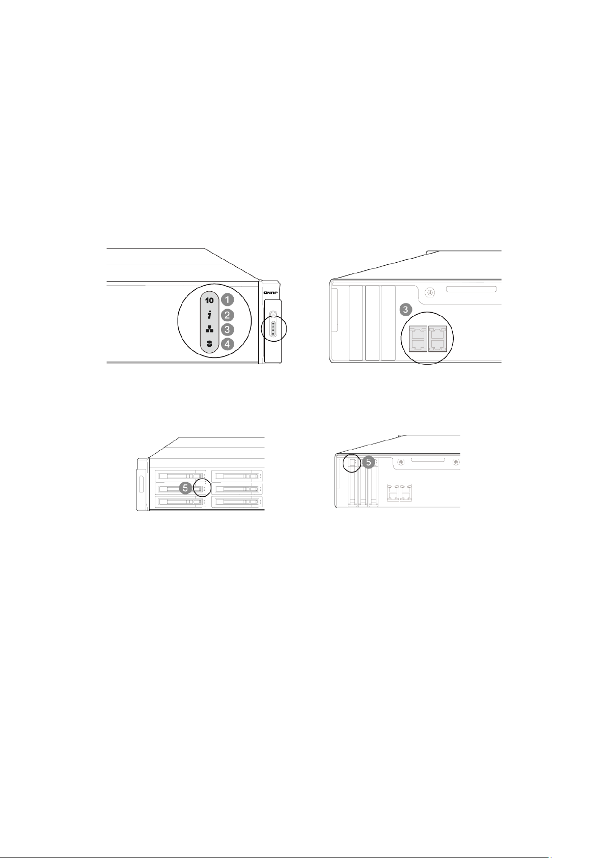
Chapter 3. LED and Alarm Buzzer Specifications
3.1 LED
The LED indicators of the NAS indicate the system status and information. When the NAS is
turned on, check the following items to make sure the system status is normal. Note that
the following LED information is applicable only when users have properly installed the hard
drive, and connected the NAS to the network and the power supply.
14
Page 15
LED
Color
LED Status
Description
10 GbE
Green
Green
The 10GbE network expansion card is
installed.
Off
No 10GbE network expansion card is
installed.
System
Status
Red/Green
Flashes green
and red
alternately
every 0.5 sec
1. The hard drive on the NAS is being
formatted.
2. The NAS is being initialized.
3. The system firmware is being
updated.
4. RAID rebuilding is in process.
5. Online RAID capacity expansion is in
process.
6. Online RAID level migration is in
process.
Red
1. The hard drive is invalid.
2. The disk volume has reached its full
capacity.
3. The disk volume is going to be full.
4. The system fan is out of function.
5. An error occurs when accessing
(read/write) the disk data.
6. A bad sector is detected on the hard
drive.
7. The NAS is in degraded read-only
mode (2 member drives fail in a RAID 5
or RAID 6 configuration, the disk data
can still be read).
8. Hardware self-test error.
Flashes red
every 0.5 sec
The NAS is in degraded mode (one
member drive fails in RAID 1, RAID 5 or
RAID 6 configuration).
Flashes green
every 0.5 sec
1. The NAS is starting up.
2. The NAS is not configured.
3. A hard disk drive is not formatted.
Green
The NAS is ready.
Deep flashes of
orange
The NAS is in sleep mode.
15
Page 16

Off
All the hard drives on the NAS are in
standby mode.
LAN
Orange
Orange
The disk data is being accessed from
the network and a read/write error
occurs during the process.
Flashes orange
The NAS is connected to the network.
Storage
Expansion
Port
Status
Orange
Off
No expansion enclosures are detected.
Orange
Expansion enclosures are detected.
HDD
Red/
Green
Flashes red
The NAS is being accessed from the
network.
Red
A hard drive read/write error occurs.
Flashes green
The disk data is being accessed.
Green
The hard drive can be accessed.
16
Page 17

3.2 Beep Alarm
Beep sound
Number of Times
Description
Short beep (0.5 sec)
1
1. The NAS is starting up.
2. The NAS is being shut down
(software shutdown).
3. The user presses the reset button to
reset the NAS.
4. The system firmware has been
updated.
Short beep (0.5 sec)
3
The NAS data cannot be copied to the
external storage device from the front
USB port.
Long beep (1.5 sec)
3, every 5 min
The system fan is out of function.
Long beep (1.5 sec)
2
1. The disk volume is going to be full.
2. The disk volume has reached its full
capacity.
3. The hard drives on the NAS are in
degraded mode.
4. The user starts the hard drive
rebuilding process.
5. A hard drive is plugged in or out.
1
1. The NAS is turned off by force
shutdown (hardware shutdown).
2. The NAS has been turned on and is
ready.
The beep alarm can be disabled in “Control Panel” > “System Settings” > “Hardware”.
17
Page 18

Chapter 4. Upgrade Memory on QNAP Turbo NAS (RAM Module
Installation)
Warning:
The following instructions should only be performed by an authorized or trained
technician.
Strictly adhere to the instructions in this section to install RAM modules in NAS. Failure
to do so could result in property damage, bodily harm or even death.
The TES-x85U series allows users to upgrade the memory in their QNAP NAS devices.
Ensure that the type of RAM is compatible with the NAS before installing. To determine how
much memory is currently in the system, log into QES/QTS as administrator and go to
“Control Panel” > “System Settings” > “System Status” to open the System Status window.
Under System Information, check for System memory or Total memory.
Carefully follow the steps below:
1. Power off the NAS. Wait for device to fully power down.
2. Disconnect power cord(s), network cable(s), and any other cables attached to the
device.
3. Before opening the NAS, wear an antistatic wrist strap and connect the crocodile clamp
to ground to prevent electrostatic discharge from damaging equipment.
4. Loosen the 2 screws on the back of the NAS located on the handle.
18
Page 19

5. Pull the handle outwards to remove the motherboard drawer.
6. Unlock the RAM slot by pressing down on the retention clamps on the sides of the RAM
slot. If replacing RAM, remove existing module from socket.
19
Page 20

7. Install new RAM:
i. Grip the new RAM on the edges to avoid touching contacts or circuitry on the
module.
ii. Line up the notch on the RAM to the break in the slot. Ensure that first RAM module
is inserted into slot 1 (see below for slot positioning).
iii. Set the stick into the slot and apply equal pressure onto both ends of the stick until
the clamps on the side click and fully lock the RAM in.
20
Page 21

8. Slide the motherboard drawer back into the NAS and pull the handle up to close
enclosure and insert screws on the handle.
9. Reconnect all cables back into the NAS.
10. Power on NAS.
11. To verify that the memory module is installed correctly and is recognized by the
operating system, log into QES/QTS as administrator and go to “Control Panel” >
“System Settings” > “System Status” > “System Information” and check for System
memory or Total memory.
21
Page 22

Chapter 5. Expansion Card Installation
Warning:
The following instructions should only be performed by an authorized or trained
technician.
Strictly adhere to the instructions in this section to install PCIe add-in card(s) in NAS.
Failure to do so could result in property damage, bodily harm or even death.
The TES-x85U series provides 4 low-profile PCIe expansion slots so that users can add
functionality to their NAS. Refer to the compatibility list at http://qnap.com/compatibility.
Follow the steps below to install add-in card:
1. Power off the NAS. Wait for device to fully power down.
2. Disconnect power cord(s), network cable(s), and any other cables attached to the
device.
3. Before opening the NAS, wear an antistatic wrist strap and connect the crocodile clamp
to ground to prevent electrostatic discharge from damaging equipment.
4. Loosen the 2 screws on the back of the NAS located on the handle.
22
Page 23

5. Pull the handle outwards to remove the motherboard drawer.
6. Remove screw from the expansion slot cover and detach cover.
23
Page 24

7. Line up the notch on the expansion card to the break in the PCIe slot. Fully insert the
expansion card to the expansion slot. Fasten screw to lock in card.
8. Slide the motherboard drawer back into the NAS and pull the handle up to close
enclosure and insert screws on the handle.
9. Reconnect all cables back into the NAS.
10. Power on NAS.
24
Page 25

Chapter 6. Install and Hot-swap Hard Drives
The TES-x85U series is compatible with 2.5-inch/3.5-inch SAS and SATA hard drives. For
hard drive compatibility list, go to http://www.qnap.com/compatibility.
Caution:
QNAP is not responsible for product damage/malfunction or data loss due to misuse or
improper installation of hard disks.
Note when a hard drive is installed in a QNAP NAS for the first time, the hard drive will
be automatically formatted and all the data on disk will be cleared.
For information on QTS NAS migration, go to docs.qnap.com and check “Migrating from
Old NAS” section.
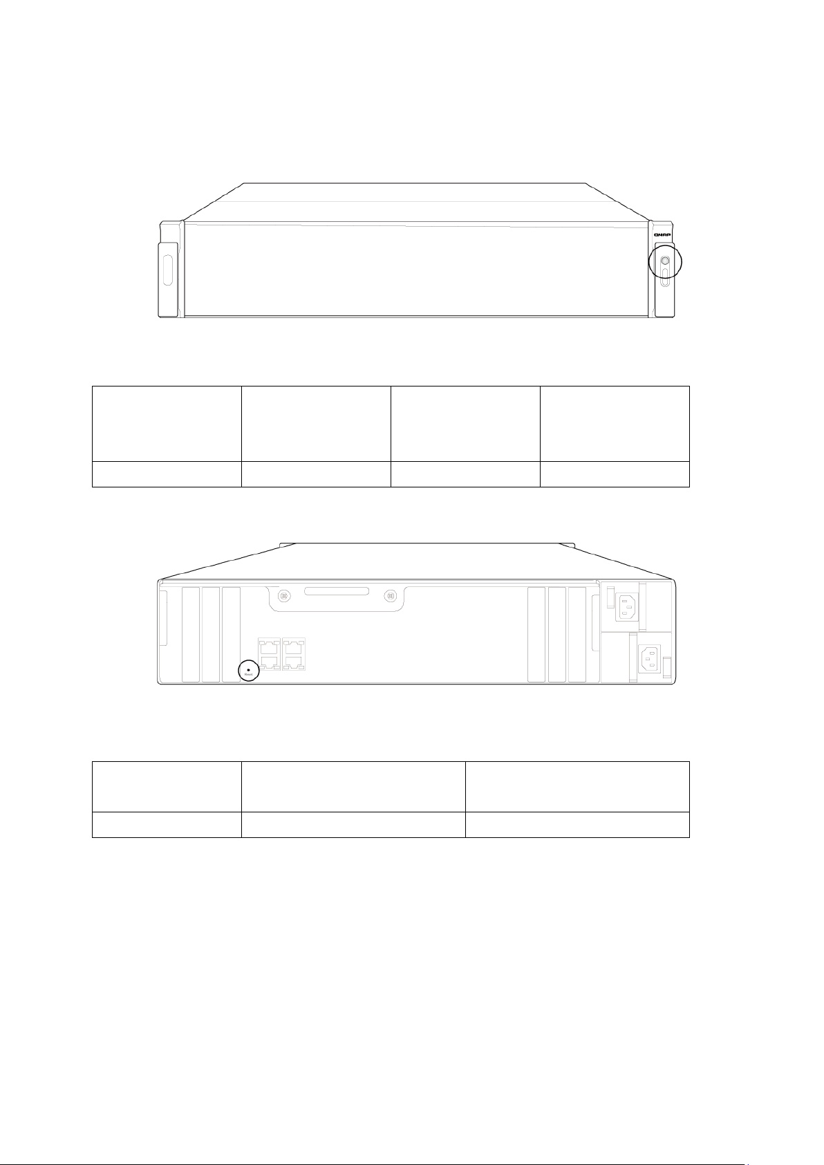
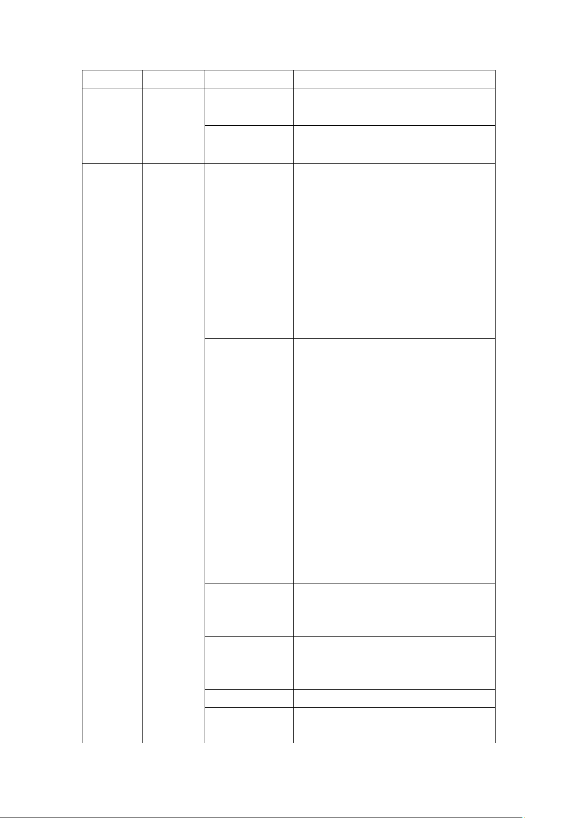
6.1 Hard Drive Bay Numbering
Identify the hard drive position in the diagram below.
1. TES-1885U (front) bay numbering:
2. TES-1885U (rear) bay numbering:
25
Page 26

TES-1885U
Front
Rear
Supports 3.5-inch SAS/SATA Hard
Drives
Yes
No
Supports 2.5-inch SAS/SATA Hard
Drives
Yes
No
Supports 2.5-inch SSD
Yes
Yes
Supports Hot-swapping Hard Drives
(RAID 1 or above)
Yes
Yes
3. TES-3085U (front) bay numbering:
4. TES-3085U (rear) bay numbering:
The TES-x85U series uses hard drive bays #1-4 on the front or the back of the unit to store
the QES operating system. The user will have the option to select the front or back drives
for the operating system during QES quick setup. The QTS operation system is stored
across all drive members in the NAS.
Note: TES-x85U series supports either the QES or QTS operating system.
26
Page 27

TES-3085U
Front
Rear
Supports 3.5-inch SAS/SATA Hard
Drives
No
No
Supports 2.5-inch SAS/SATA Hard
Drives
Yes
No
Supports 2.5-inch SSD
Yes
Yes
Supports Hot-swapping Hard Drives
(RAID 1 or above)
Yes
Yes
6.2 Install Hard Drives
To install hard drives in NAS, follow the steps below:
1. Unlock drive tray and remove from enclosure.
27
Page 28

2. Install a 3.5" or 2.5" disk drive to the tray.
3. Insert the drive tray into the NAS, close and lock the latch.
28
Page 29

4. To verify that the hard drive has been correctly installed and recognized by the
operating system, log into QES/QTS as administrator and go to “Storage Manager” >
“Storage” > “Disks” or “Disks/VJOB” and confirm the disk is in the System Component or
NAS Host section.
6.3 RAID Recovery - Hot-Swap Hard Drives
The TES-x85U series supports hot-swapping hard drives. When one drive fails in RAID 1/5,
up to two drives fail in RAID 6/RAID 10*/Triple Mirror**, or up to three drives fail in
RAID-TP**, replacing failed drives with a healthy ones will automatically trigger QES/QTS
to rebuild the RAID. Follow the steps below to hot-swap hard drives when drive failures
occur in a RAID configuration. See section 6.2 for detailed instructions on how to install a
new drive.
* One drive each in the RAID 1 pair
** QES only
Follow instructions below for hot-swapping:
1. Log into QES/QTS as administrator and check the storage pool status in “Storage
Manager” > “Storage” > “Storage Space”. There will be a list of all available storage
pools.
2. If one drive fails in RAID 1/5, up to two drives fail in RAID 6/RAID 10*/Triple Mirror**,
or up to three drives fail in RAID-TP**, the storage pool status will be labeled as
“Degraded” and the Volume/RAID group status should be labeled as “Warning”.
3. Go to “Storage Manager” > “Storage” > “Disks” or “Disks/VJBOD” to determine which
disk needs to be replaced.
4. Take out bad drive from NAS enclosure and remove hard drive from tray.
5. Install replacement hard drive onto tray.
Note: the capacity of the new drive must be equal to or greater than the capacity of the old
drive.
29
Page 30

7. Insert tray with hard drive installed into NAS.
Important: Wait for two beeps after removing the faulty hard drive before inserting
replacement drive into NAS. The NAS should also beep twice after replacement hard
drive is installed.
8. The volume should automatically rebuild. Go to “Storage Manager” > “Storage” >
“Storage Space” to confirm.
30
Page 31

6.4 RAID Recovery - Accidentally Removal of Healthy Hard Drive (QTS)
Initial
Status
Status After Healthy
Drive is Removed
Status After Drive is
Re-Inserted and Storage
Pool is Recovered
RAID 0/JBOD
Ready
Not active
Ready
RAID 1/5/6
Ready
Degraded
Rebuilding
RAID 1/5/6
Degraded
Not active
Degraded
The TES-x85U series supports RAID recovery when a healthy drive is unexpectedly
removed from a RAID 1/5/6 during hot-swapping or RAID 0/JBOD configuration in QTS.
Note that RAID 10 does not support this feature.
When a healthy drive is unexpectedly removed from a RAID group, the status of the RAID
will change to “Not active”. To recover from an “Not active” status:
1. Re-insert all hard drives back into the NAS in its original order. This includes any bad
drive(s) that will need to be replaced after recovery.
2. Log into QTS as administrator and go to “Storage Manager” > “Storage” > “Storage
Space”.
3. Double click on the affected Storage Pool to open the Storage Pool Management
window.
4. In the “Storage Pool Management” window, click on the “Manage” button and select
“Recover”.
The process should take about 60 seconds for QTS to complete. When recovery is
completed, the RAID group should be restored to its initial status.
See chart below for RAID status during this process.
31
Page 32

The chart below describes the events of an error when using RAID 5.
RAID 5 (Minimum 3 Disks)
QTS
Standard
One drive fails
Degraded mode (may still read
and write).
Degraded mode (may still read
and write).
One drive fails
and there are bad
sectors found in
the other drive(s)
Read only protect mode (for
immediate data backup & hard
drive replacement).
RAID crash.
2 hard drives fail
RAID crash.
RAID crash.
RAID 6 (Minimum 4 Disks)
QTS
Standard
One or two drives
drive fail
Degraded mode. (may still read
and write).
Degraded mode. (may still read
and write).
Two drives fail
and there are bad
sectors found in
the other drive(s)
Read only protect mode (for
immediate data backup & hard
drive replacement).
RAID crash.
3 hard drives fail
RAID crash.
RAID crash.
The chart below describes the events of an error when using RAID 6.
32
Page 33

Chapter 7. Install Power Supply Unit and Redundant Power
Supply Mode
Note: The following instructions should only be performed by an authorized or trained
technician.
7.1 Replace Power Supply Unit
To replace a failed power supply unit on the TES-x85U series, follow the steps below.
1. Power off the NAS. Wait for device to fully power down.
2. Disconnect power cord(s), network cable(s), and any other cables attached to the
device.
3. Firmly press and hold the orange button on back of PSU towards the black handle. Pull
out power supply by pulling black handle.
33
Page 34

4. Insert new power supply into NAS.
5. Connect the power adaptor and cables to the NAS.
6. Power on NAS.
34
Page 35

7.2 Redundant Power Supply Mode
If two power supply units (PSU) have been installed on the NAS, both PSUs will supply
power to the NAS. Redundant Power Supply Mode is a feature that will alert users of a PSU
failure or power interruption. The NAS will beep and log an error message in the “System
Logs”. Redundant Power Supply Mode can be enabled in QES/QTS under “Control Panel” >
“System Settings” > “Hardware” > “General” > “Enable Redundant Power Supply Mode”. It
is not recommended for uses to enable this feature for only one PSU. This function is
disabled by default.
WARNING: RISK OF ELECTRIC SHOCK
The connectors on the back panel (bracketed parts below) contain high voltage. Do NOT
touch these parts to avoid the risk of electric shock to the maintenance operator.
35
Page 36

Technical Support
QNAP provides dedicated online support and customer service via instant messenger.
Online Support: http://www.qnap.com
Forum: http://forum.qnap.com
Technical Support in the USA and Canada:
Online Support: helpdesk.qnap.com
TEL: +1-909-595-2782 #3
Address: 168 University Parkway, Pomona CA 91768
Service Hours: 06:00-18:00 (GMT-8 08:00 Pacific Time, Monday to Friday)
36
Page 37

GNU GENERAL PUBLIC LICENSE
Version 3, 29 June 2007
Copyright © 2007 Free Software Foundation, Inc. <http://fsf.org/>
Everyone is permitted to copy and distribute verbatim copies of this license document, but
changing it is not allowed.
Preamble
The GNU General Public License is a free, copyleft license for software and other kinds of
works.
The licenses for most software and other practical works are designed to take away your
freedom to share and change the works. By contrast, the GNU General Public License is
intended to guarantee your freedom to share and change all versions of a program--to
make sure it remains free software for all its users. We, the Free Software Foundation, use
the GNU General Public License for most of our software; it applies also to any other work
released this way by its authors. You can apply it to your programs, too.
When we speak of free software, we are referring to freedom, not price. Our General Public
Licenses are designed to make sure that you have the freedom to distribute copies of free
software (and charge for them if you wish), that you receive source code or can get it if you
want it, that you can change the software or use pieces of it in new free programs, and that
you know you can do these things.
To protect your rights, we need to prevent others from denying you these rights or asking
you to surrender the rights. Therefore, you have certain responsibilities if you distribute
copies of the software, or if you modify it: responsibilities to respect the freedom of others.
For example, if you distribute copies of such a program, whether gratis or for a fee, you
must pass on to the recipients the same freedoms that you received. You must make sure
that they, too, receive or can get the source code. And you must show them these terms so
they know their rights.
Developers that use the GNU GPL protect your rights with two steps: (1) assert copyright
on the software, and (2) offer you this License giving you legal permission to copy,
distribute and/or modify it.
37
Page 38

For the developers' and authors' protection, the GPL clearly explains that there is no
warranty for this free software. For both users' and authors' sake, the GPL requires that
modified versions be marked as changed, so that their problems will not be attributed
erroneously to authors of previous versions.
Some devices are designed to deny users access to install or run modified versions of the
software inside them, although the manufacturer can do so. This is fundamentally
incompatible with the aim of protecting users' freedom to change the software. The
systematic pattern of such abuse occurs in the area of products for individuals to use, which
is precisely where it is most unacceptable. Therefore, we have designed this version of the
GPL to prohibit the practice for those products. If such problems arise substantially in other
domains, we stand ready to extend this provision to those domains in future versions of the
GPL, as needed to protect the freedom of users.
Finally, every program is threatened constantly by software patents. States should not
allow patents to restrict development and use of software on general-purpose computers,
but in those that do, we wish to avoid the special danger that patents applied to a free
program could make it effectively proprietary. To prevent this, the GPL assures that patents
cannot be used to render the program non-free.
The precise terms and conditions for copying, distribution and modification follow.
TERMS AND CONDITIONS
0. Definitions.
“This License” refers to version 3 of the GNU General Public License.
“Copyright” also means copyright-like laws that apply to other kinds of works, such as
semiconductor masks.
“The Program” refers to any copyrightable work licensed under this License. Each licensee
is addressed as “you”. “Licensees” and “recipients” may be individuals or organizations.
To “modify” a work means to copy from or adapt all or part of the work in a fashion requiring
copyright permission, other than the making of an exact copy. The resulting work is called
a “modified version” of the earlier work or a work “based on” the earlier work.
A “covered work” means either the unmodified Program or a work based on the Program.
38
Page 39

To “propagate” a work means to do anything with it that, without permission, would make
you directly or secondarily liable for infringement under applicable copyright law, except
executing it on a computer or modifying a private copy. Propagation includes copying,
distribution (with or without modification), making available to the public, and in some
countries other activities as well.
To “convey” a work means any kind of propagation that enables other parties to make or
receive copies. Mere interaction with a user through a computer network, with no transfer
of a copy, is not conveying.
An interactive user interface displays “Appropriate Legal Notices” to the extent that it
includes a convenient and prominently visible feature that (1) displays an appropriate
copyright notice, and (2) tells the user that there is no warranty for the work (except to the
extent that warranties are provided), that licensees may convey the work under this
License, and how to view a copy of this License. If the interface presents a list of user
commands or options, such as a menu, a prominent item in the list meets this criterion.
1. Source Code.
The “source code” for a work means the preferred form of the work for making
modifications to it. “Object code” means any non-source form of a work.
A “Standard Interface” means an interface that either is an official standard defined by a
recognized standards body, or, in the case of interfaces specified for a particular
programming language, one that is widely used among developers working in that
language.
The “System Libraries” of an executable work include anything, other than the work as a
whole, that (a) is included in the normal form of packaging a Major Component, but which
is not part of that Major Component, and (b) serves only to enable use of the work with that
Major Component, or to implement a Standard Interface for which an implementation is
available to the public in source code form. A “Major Component”, in this context, means a
major essential component (kernel, window system, and so on) of the specific operating
system (if any) on which the executable work runs, or a compiler used to produce the work,
or an object code interpreter used to run it.
The “Corresponding Source” for a work in object code form means all the source code
needed to generate, install, and (for an executable work) run the object code and to modify
39
Page 40

the work, including scripts to control those activities. However, it does not include the
work's System Libraries, or general-purpose tools or generally available free programs
which are used unmodified in performing those activities but which are not part of the work.
For example, Corresponding Source includes interface definition files associated with
source files for the work, and the source code for shared libraries and dynamically linked
subprograms that the work is specifically designed to require, such as by intimate data
communication or control flow between those subprograms and other parts of the work.
The Corresponding Source need not include anything that users can regenerate
automatically from other parts of the Corresponding Source.
The Corresponding Source for a work in source code form is that same work.
2. Basic Permissions.
All rights granted under this License are granted for the term of copyright on the Program,
and are irrevocable provided the stated conditions are met. This License explicitly affirms
your unlimited permission to run the unmodified Program. The output from running a
covered work is covered by this License only if the output, given its content, constitutes a
covered work. This License acknowledges your rights of fair use or other equivalent, as
provided by copyright law.
You may make, run and propagate covered works that you do not convey, without
conditions so long as your license otherwise remains in force. You may convey covered
works to others for the sole purpose of having them make modifications exclusively for you,
or provide you with facilities for running those works, provided that you comply with the
terms of this License in conveying all material for which you do not control copyright. Those
thus making or running the covered works for you must do so exclusively on your behalf,
under your direction and control, on terms that prohibit them from making any copies of
your copyrighted material outside their relationship with you.
Conveying under any other circumstances is permitted solely under the conditions stated
below. Sublicensing is not allowed; section 10 makes it unnecessary.
3. Protecting Users' Legal Rights From Anti-Circumvention Law.
No covered work shall be deemed part of an effective technological measure under any
applicable law fulfilling obligations under article 11 of the WIPO copyright treaty adopted on
20 December 1996, or similar laws prohibiting or restricting circumvention of such
measures.
40
Page 41

When you convey a covered work, you waive any legal power to forbid circumvention of
technological measures to the extent such circumvention is effected by exercising rights
under this License with respect to the covered work, and you disclaim any intention to limit
operation or modification of the work as a means of enforcing, against the work's users,
your or third parties' legal rights to forbid circumvention of technological measures.
4. Conveying Verbatim Copies.
You may convey verbatim copies of the Program's source code as you receive it, in any
medium, provided that you conspicuously and appropriately publish on each copy an
appropriate copyright notice; keep intact all notices stating that this License and any
non-permissive terms added in accord with section 7 apply to the code; keep intact all
notices of the absence of any warranty; and give all recipients a copy of this License along
with the Program.
You may charge any price or no price for each copy that you convey, and you may offer
support or warranty protection for a fee.
5. Conveying Modified Source Versions.
You may convey a work based on the Program, or the modifications to produce it from the
Program, in the form of source code under the terms of section 4, provided that you also
meet all of these conditions:
a) The work must carry prominent notices stating that you modified it, and giving a
relevant date.
b) The work must carry prominent notices stating that it is released under this License and
any conditions added under section 7. This requirement modifies the requirement in
section 4 to “keep intact all notices”.
c) You must license the entire work, as a whole, under this License to anyone who comes
into possession of a copy. This License will therefore apply, along with any applicable
section 7 additional terms, to the whole of the work, and all its parts, regardless of how
they are packaged. This License gives no permission to license the work in any other way,
but it does not invalidate such permission if you have separately received it.
d) If the work has interactive user interfaces, each must display Appropriate Legal Notices;
however, if the Program has interactive interfaces that do not display Appropriate Legal
Notices, your work need not make them do so.
A compilation of a covered work with other separate and independent works, which are not
by their nature extensions of the covered work, and which are not combined with it such as
41
Page 42

to form a larger program, in or on a volume of a storage or distribution medium, is called an
“aggregate” if the compilation and its resulting copyright are not used to limit the access or
legal rights of the compilation's users beyond what the individual works permit. Inclusion of
a covered work in an aggregate does not cause this License to apply to the other parts of
the aggregate.
6. Conveying Non-Source Forms.
You may convey a covered work in object code form under the terms of sections 4 and 5,
provided that you also convey the machine-readable Corresponding Source under the
terms of this License, in one of these ways:
a) Convey the object code in, or embodied in, a physical product (including a physical
distribution medium), accompanied by the Corresponding Source fixed on a durable
physical medium customarily used for software interchange.
b) Convey the object code in, or embodied in, a physical product (including a physical
distribution medium), accompanied by a written offer, valid for at least three years and
valid for as long as you offer spare parts or customer support for that product model, to
give anyone who possesses the object code either (1) a copy of the Corresponding Source
for all the software in the product that is covered by this License, on a durable physical
medium customarily used for software interchange, for a price no more than your
reasonable cost of physically performing this conveying of source, or (2) access to copy the
Corresponding Source from a network server at no charge.
c) Convey individual copies of the object code with a copy of the written offer to provide the
Corresponding Source. This alternative is allowed only occasionally and noncommercially,
and only if you received the object code with such an offer, in accord with subsection 6b.
d) Convey the object code by offering access from a designated place (gratis or for a
charge), and offer equivalent access to the Corresponding Source in the same way through
the same place at no further charge. You need not require recipients to copy the
Corresponding Source along with the object code. If the place to copy the object code is a
network server, the Corresponding Source may be on a different server (operated by you or
a third party) that supports equivalent copying facilities, provided you maintain clear
directions next to the object code saying where to find the Corresponding Source.
Regardless of what server hosts the Corresponding Source, you remain obligated to ensure
that it is available for as long as needed to satisfy these requirements.
e) Convey the object code using peer-to-peer transmission, provided you inform other
peers where the object code and Corresponding Source of the work are being offered to the
general public at no charge under subsection 6d.
A separable portion of the object code, whose source code is excluded from the
42
Page 43

Corresponding Source as a System Library, need not be included in conveying the object
code work.
A “User Product” is either (1) a “consumer product”, which means any tangible personal
property which is normally used for personal, family, or household purposes, or (2)
anything designed or sold for incorporation into a dwelling. In determining whether a
product is a consumer product, doubtful cases shall be resolved in favor of coverage. For a
particular product received by a particular user, “normally used” refers to a typical or
common use of that class of product, regardless of the status of the particular user or of the
way in which the particular user actually uses, or expects or is expected to use, the product.
A product is a consumer product regardless of whether the product has substantial
commercial, industrial or non-consumer uses, unless such uses represent the only
significant mode of use of the product.
“Installation Information” for a User Product means any methods, procedures,
authorization keys, or other information required to install and execute modified versions
of a covered work in that User Product from a modified version of its Corresponding Source.
The information must suffice to ensure that the continued functioning of the modified
object code is in no case prevented or interfered with solely because modification has been
made.
If you convey an object code work under this section in, or with, or specifically for use in,
a User Product, and the conveying occurs as part of a transaction in which the right of
possession and use of the User Product is transferred to the recipient in perpetuity or for a
fixed term (regardless of how the transaction is characterized), the Corresponding Source
conveyed under this section must be accompanied by the Installation Information. But this
requirement does not apply if neither you nor any third party retains the ability to install
modified object code on the User Product (for example, the work has been installed in
ROM).
The requirement to provide Installation Information does not include a requirement to
continue to provide support service, warranty, or updates for a work that has been modified
or installed by the recipient, or for the User Product in which it has been modified or
installed. Access to a network may be denied when the modification itself materially and
adversely affects the operation of the network or violates the rules and protocols for
communication across the network.
Corresponding Source conveyed, and Installation Information provided, in accord with this
43
Page 44

section must be in a format that is publicly documented (and with an implementation
available to the public in source code form), and must require no special password or key
for unpacking, reading or copying.
7. Additional Terms.
“Additional permissions” are terms that supplement the terms of this License by making
exceptions from one or more of its conditions. Additional permissions that are applicable to
the entire Program shall be treated as though they were included in this License, to the
extent that they are valid under applicable law. If additional permissions apply only to part
of the Program, that part may be used separately under those permissions, but the entire
Program remains governed by this License without regard to the additional permissions.
When you convey a copy of a covered work, you may at your option remove any additional
permissions from that copy, or from any part of it. (Additional permissions may be written
to require their own removal in certain cases when you modify the work.) You may place
additional permissions on material, added by you to a covered work, for which you have or
can give appropriate copyright permission.
Notwithstanding any other provision of this License, for material you add to a covered work,
you may (if authorized by the copyright holders of that material) supplement the terms of
this License with terms:
a) Disclaiming warranty or limiting liability differently from the terms of sections 15 and 16
of this License; or
b) Requiring preservation of specified reasonable legal notices or author attributions in that
material or in the Appropriate Legal Notices displayed by works containing it; or
c) Prohibiting misrepresentation of the origin of that material, or requiring that modified
versions of such material be marked in reasonable ways as different from the original
version; or
d) Limiting the use for publicity purposes of names of licensors or authors of the material;
or
e) Declining to grant rights under trademark law for use of some trade names, trademarks,
or service marks; or
f) Requiring indemnification of licensors and authors of that material by anyone who
conveys the material (or modified versions of it) with contractual assumptions of liability to
the recipient, for any liability that these contractual assumptions directly impose on those
licensors and authors.
All other non-permissive additional terms are considered “further restrictions” within the
44
Page 45

meaning of section 10. If the Program as you received it, or any part of it, contains a notice
stating that it is governed by this License along with a term that is a further restriction, you
may remove that term. If a license document contains a further restriction but permits
relicensing or conveying under this License, you may add to a covered work material
governed by the terms of that license document, provided that the further restriction does
not survive such relicensing or conveying.
If you add terms to a covered work in accord with this section, you must place, in the
relevant source files, a statement of the additional terms that apply to those files, or a
notice indicating where to find the applicable terms.
Additional terms, permissive or non-permissive, may be stated in the form of a separately
written license, or stated as exceptions; the above requirements apply either way.
8. Termination.
You may not propagate or modify a covered work except as expressly provided under this
License. Any attempt otherwise to propagate or modify it is void, and will automatically
terminate your rights under this License (including any patent licenses granted under the
third paragraph of section 11).
However, if you cease all violation of this License, then your license from a particular
copyright holder is reinstated (a) provisionally, unless and until the copyright holder
explicitly and finally terminates your license, and (b) permanently, if the copyright holder
fails to notify you of the violation by some reasonable means prior to 60 days after the
cessation.
Moreover, your license from a particular copyright holder is reinstated permanently if the
copyright holder notifies you of the violation by some reasonable means, this is the first
time you have received notice of violation of this License (for any work) from that copyright
holder, and you cure the violation prior to 30 days after your receipt of the notice.
Termination of your rights under this section does not terminate the licenses of parties who
have received copies or rights from you under this License. If your rights have been
terminated and not permanently reinstated, you do not qualify to receive new licenses for
the same material under section 10.
9. Acceptance Not Required for Having Copies.
You are not required to accept this License in order to receive or run a copy of the Program.
45
Page 46

Ancillary propagation of a covered work occurring solely as a consequence of using
peer-to-peer transmission to receive a copy likewise does not require acceptance. However,
nothing other than this License grants you permission to propagate or modify any covered
work. These actions infringe copyright if you do not accept this License. Therefore, by
modifying or propagating a covered work, you indicate your acceptance of this License to
do so.
10. Automatic Licensing of Downstream Recipients.
Each time you convey a covered work, the recipient automatically receives a license from
the original licensors, to run, modify and propagate that work, subject to this License. You
are not responsible for enforcing compliance by third parties with this License.
An “entity transaction” is a transaction transferring control of an organization, or
substantially all assets of one, or subdividing an organization, or merging organizations. If
propagation of a covered work results from an entity transaction, each party to that
transaction who receives a copy of the work also receives whatever licenses to the work the
party's predecessor in interest had or could give under the previous paragraph, plus a right
to possession of the Corresponding Source of the work from the predecessor in interest, if
the predecessor has it or can get it with reasonable efforts.
You may not impose any further restrictions on the exercise of the rights granted or
affirmed under this License. For example, you may not impose a license fee, royalty, or
other charge for exercise of rights granted under this License, and you may not initiate
litigation (including a cross-claim or counterclaim in a lawsuit) alleging that any patent
claim is infringed by making, using, selling, offering for sale, or importing the Program or
any portion of it.
11. Patents.
A “contributor” is a copyright holder who authorizes use under this License of the Program
or a work on which the Program is based. The work thus licensed is called the contributor's
“contributor version”.
A contributor's “essential patent claims” are all patent claims owned or controlled by the
contributor, whether already acquired or hereafter acquired, that would be infringed by
some manner, permitted by this License, of making, using, or selling its contributor version,
but do not include claims that would be infringed only as a consequence of further
modification of the contributor version. For purposes of this definition, “control” includes
the right to grant patent sublicenses in a manner consistent with the requirements of this
46
Page 47

License.
Each contributor grants you a non-exclusive, worldwide, royalty-free patent license under
the contributor's essential patent claims, to make, use, sell, offer for sale, import and
otherwise run, modify and propagate the contents of its contributor version.
In the following three paragraphs, a “patent license” is any express agreement or
commitment, however denominated, not to enforce a patent (such as an express
permission to practice a patent or covenant not to sue for patent infringement). To “grant”
such a patent license to a party means to make such an agreement or commitment not to
enforce a patent against the party.
If you convey a covered work, knowingly relying on a patent license, and the Corresponding
Source of the work is not available for anyone to copy, free of charge and under the terms
of this License, through a publicly available network server or other readily accessible
means, then you must either (1) cause the Corresponding Source to be so available, or (2)
arrange to deprive yourself of the benefit of the patent license for this particular work, or (3)
arrange, in a manner consistent with the requirements of this License, to extend the patent
license to downstream recipients. “Knowingly relying” means you have actual knowledge
that, but for the patent license, your conveying the covered work in a country, or your
recipient's use of the covered work in a country, would infringe one or more identifiable
patents in that country that you have reason to believe are valid.
If, pursuant to or in connection with a single transaction or arrangement, you convey, or
propagate by procuring conveyance of, a covered work, and grant a patent license to some
of the parties receiving the covered work authorizing them to use, propagate, modify or
convey a specific copy of the covered work, then the patent license you grant is
automatically extended to all recipients of the covered work and works based on it.
A patent license is “discriminatory” if it does not include within the scope of its coverage,
prohibits the exercise of, or is conditioned on the non-exercise of one or more of the rights
that are specifically granted under this License. You may not convey a covered work if you
are a party to an arrangement with a third party that is in the business of distributing
software, under which you make payment to the third party based on the extent of your
activity of conveying the work, and under which the third party grants, to any of the parties
who would receive the covered work from you, a discriminatory patent license (a) in
connection with copies of the covered work conveyed by you (or copies made from those
copies), or (b) primarily for and in connection with specific products or compilations that
47
Page 48

contain the covered work, unless you entered into that arrangement, or that patent license
was granted, prior to 28 March 2007.
Nothing in this License shall be construed as excluding or limiting any implied license or
other defenses to infringement that may otherwise be available to you under applicable
patent law.
12. No Surrender of Others' Freedom.
If conditions are imposed on you (whether by court order, agreement or otherwise) that
contradict the conditions of this License, they do not excuse you from the conditions of this
License. If you cannot convey a covered work so as to satisfy simultaneously your
obligations under this License and any other pertinent obligations, then as a consequence
you may not convey it at all. For example, if you agree to terms that obligate you to collect
a royalty for further conveying from those to whom you convey the Program, the only way
you could satisfy both those terms and this License would be to refrain entirely from
conveying the Program.
13. Use with the GNU Affero General Public License.
Notwithstanding any other provision of this License, you have permission to link or combine
any covered work with a work licensed under version 3 of the GNU Affero General Public
License into a single combined work, and to convey the resulting work. The terms of this
License will continue to apply to the part which is the covered work, but the special
requirements of the GNU Affero General Public License, section 13, concerning interaction
through a network will apply to the combination as such.
14. Revised Versions of this License.
The Free Software Foundation may publish revised and/or new versions of the GNU General
Public License from time to time. Such new versions will be similar in spirit to the present
version, but may differ in detail to address new problems or concerns.
Each version is given a distinguishing version number. If the Program specifies that a
certain numbered version of the GNU General Public License “or any later version” applies
to it, you have the option of following the terms and conditions either of that numbered
version or of any later version published by the Free Software Foundation. If the Program
does not specify a version number of the GNU General Public License, you may choose any
version ever published by the Free Software Foundation.
If the Program specifies that a proxy can decide which future versions of the GNU General
48
Page 49

Public License can be used, that proxy's public statement of acceptance of a version
permanently authorizes you to choose that version for the Program.
Later license versions may give you additional or different permissions. However, no
additional obligations are imposed on any author or copyright holder as a result of your
choosing to follow a later version.
15. Disclaimer of Warranty.
THERE IS NO WARRANTY FOR THE PROGRAM, TO THE EXTENT PERMITTED BY APPLICABLE
LAW. EXCEPT WHEN OTHERWISE STATED IN WRITING THE COPYRIGHT HOLDERS AND/OR
OTHER PARTIES PROVIDE THE PROGRAM “AS IS” WITHOUT WARRANTY OF ANY KIND,
EITHER EXPRESSED OR IMPLIED, INCLUDING, BUT NOT LIMITED TO, THE IMPLIED
WARRANTIES OF MERCHANTABILITY AND FITNESS FOR A PARTICULAR PURPOSE. THE
ENTIRE RISK AS TO THE QUALITY AND PERFORMANCE OF THE PROGRAM IS WITH YOU.
SHOULD THE PROGRAM PROVE DEFECTIVE, YOU ASSUME THE COST OF ALL NECESSARY
SERVICING, REPAIR OR CORRECTION.
16. Limitation of Liability.
IN NO EVENT UNLESS REQUIRED BY APPLICABLE LAW OR AGREED TO IN WRITING WILL
ANY COPYRIGHT HOLDER, OR ANY OTHER PARTY WHO MODIFIES AND/OR CONVEYS THE
PROGRAM AS PERMITTED ABOVE, BE LIABLE TO YOU FOR DAMAGES, INCLUDING ANY
GENERAL, SPECIAL, INCIDENTAL OR CONSEQUENTIAL DAMAGES ARISING OUT OF THE
USE OR INABILITY TO USE THE PROGRAM (INCLUDING BUT NOT LIMITED TO LOSS OF
DATA OR DATA BEING RENDERED INACCURATE OR LOSSES SUSTAINED BY YOU OR THIRD
PARTIES OR A FAILURE OF THE PROGRAM TO OPERATE WITH ANY OTHER PROGRAMS),
EVEN IF SUCH HOLDER OR OTHER PARTY HAS BEEN ADVISED OF THE POSSIBILITY OF
SUCH DAMAGES.
17. Interpretation of Sections 15 and 16.
If the disclaimer of warranty and limitation of liability provided above cannot be given local
legal effect according to their terms, reviewing courts shall apply local law that most closely
approximates an absolute waiver of all civil liability in connection with the Program, unless
a warranty or assumption of liability accompanies a copy of the Program in return for a fee.
END OF TERMS AND CONDITIONS
49
 Loading...