

Page 1

GM-1000
GM-1001
GM-1002
User Guide
Document Version: 1
01/07/2020
Page 2

GM-1000 User Guide
Contents
1. Preface
About This Guide.......................................................................................................................................... 3
Audience.......................................................................................................................................................3
Document Conventions................................................................................................................................ 3
2. Product Overview
About the GM-1000...................................................................................................................................... 4
Hardware Specifications............................................................................................................................... 4
Package Contents........................................................................................................................................ 7
Components................................................................................................................................................. 7
Enclosure..................................................................................................................................................7
Node.......................................................................................................................................................14
Drive Numbering.....................................................................................................................................18
Safety Information.......................................................................................................................................19
Installation Requirements........................................................................................................................... 20
Setting Up the NAS.....................................................................................................................................21
3. Installation and Configuration
Hardware Installation.................................................................................................................................. 22
Removing a Node...................................................................................................................................22
Installing a Node.....................................................................................................................................23
Drive Installation.....................................................................................................................................24
Installing Expansion Cards.....................................................................................................................32
Replacing Memory Modules...................................................................................................................35
Hot-swapping Redundant Power Supply Units.......................................................................................37
Installing Expansion Units...................................................................................................................... 38
QuTS hero Installation................................................................................................................................ 42
Installing QuTS hero Using Qfinder Pro................................................................................................. 43
Installing QuTS hero Using the Cloud Key.............................................................................................44
4. Troubleshooting
Forcing Qfinder Pro or myQNAPcloud to Locate the NAS......................................................................... 47
Hot-swapping Failed Drives........................................................................................................................47
Support and Other Resources.................................................................................................................... 47
5. Glossary
Cloud Key................................................................................................................................................... 49
myQNAPcloud Link.....................................................................................................................................49
myQNAPcloud............................................................................................................................................ 49
myQNAPcloud ID........................................................................................................................................49
Qfinder Pro................................................................................................................................................. 49
QuTS hero.................................................................................................................................................. 49
6. Notices
Limited Warranty.........................................................................................................................................50
Disclaimer................................................................................................................................................... 50
BSMI Notice................................................................................................................................................50
CE Notice....................................................................................................................................................51
FCC Notice................................................................................................................................................. 51
SJ/T 11364-2006.........................................................................................................................................51
1
Page 3

VCCI Notice................................................................................................................................................ 52
2
Page 4
GM-1000 User Guide
1. Preface
About This Guide
This guide provides information on the QNAP GM-1000 NAS and step-by-step instructions on installing the
hardware. It also provides instructions on basic operations and troubleshooting information.
Audience
This document is intended for storage administrators. This guide assumes that the user is knowledgeable
and qualified to install, maintain, and troubleshoot issues involving servers, server components, and storage
systems. This guide also assumes that the user is trained to recognize hazards, including the appropriate
actions the user needs to take to prevent personal injury and damage to data and property.
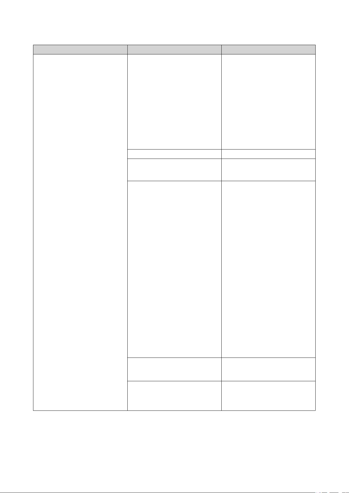
Document Conventions
Symbol Description
Notes provide default configuration settings and other supplementary
information.
Important notes provide information on required configuration settings and other
critical information.
Tips provide recommendations or alternative methods of performing tasks or
configuring settings.
Warnings provide information that, when ignored, may result in potential loss,
injury, or even death.
Preface 3
Page 5
GM-1000 User Guide
2. Product Overview
This chapter provides basic information about the QNAP device.
About the GM-1000
The GM-1000 is a ZFS NAS designed to provide efficient data backup and hybrid cloud solutions for
enterprises. The dual NAS comprises two replaceable nodes, where the GM-1001 has a 3.6 GHz for each
CPU base frequency and the GM-1002 has a 3.4 for each CPU base frequency. The enclosure also contains
sixteen 3.5-inch drive bays where a single node controls eight SATA drives on the front, two U.2 and SATA
drives on the back, and two NVMe M.2 SSDs on the system board. Each node is equipped with two 2.5
Gigabit Ethernet ports and two 10 Gigabit Ethernet ports, making the GM-1000 ideal for bandwidthdemanding applications.
Hardware Specifications
Warning
• If your QNAP product has hardware defects, return the product to QNAP or a QNAPauthorized service center for maintenance or replacement. Any attempt to repair or
perform maintenance procedures on the product by you or an unauthorized third-party
invalidates the warranty.
• QNAP is not responsible for any damage or data loss caused by unauthorized
modifications and installation of unsupported third-party applications.
• For details, see the QNAP Warranty Terms and Conditions.
Tip
Model specifications are subject to change without prior notice. To see the latest
specifications, go to https://www.qnap.com.
Note
• The hardware specifications table is separated into components found on the
enclosure, the node, and the system.
• The components presented in the node applies to a single node.
Ordering P/N Enclosure Node CPU Memory
GM-1001 1 x TEC-2N16-770W 2 x TNS-h1083X-
E2234-8G
GM-1002 2 x TNS-h1083X-
E2236-16G
Component GM-1001 GM-1002
Enclosure
Name TEC-2N16-770W
Storage
Intel® Xeon®
E-2234
Intel® Xeon®
E-2236
8 GB
16 GB
Product Overview 4
Page 6
Component GM-1001 GM-1002
Drive bays 16 x 3.5-inch SATA 6 Gbps
Note
One node controls eight drives.
Drive compatibility 3.5-inch bays:
• 3.5-inch SATA hard disk drives
• 2.5-inch SATA hard disk drives
• 2.5-inch SATA solid-state drives
Interface
Buttons • Power
• OLED
Others
Power supply unit 2 x 770W, 100-240V AC, 50-60 Hz
Node
GM-1000 User Guide
Note
The components in this section apply to a single node.
Name TNS-h1083X-E2234-8G TNS-h1083X-E2236-16G
Processor
CPU Intel® Xeon® E-2234 Intel® Xeon® E-2236
Frequency 4-core 3.6 GHz base/4.8 GHz
burst
6-core 3.4 GHz base/4.8 GHz
burst
Architecture x86 64-bit
Encryption engine AES-NI
Memory
Pre-installed memory 8 GB RAM: 2 x 4 GB UDIMM
DDR4
16 GB RAM: 2 x 8 GB UDIMM
DDR4
Memory slots 4 x Long-DIMM DDR4
Important
• Use only QNAP memory modules to maintain
system performance and stability. For NAS
devices with more than one memory slot, use
QNAP modules with identical specifications.
• Using unsupported modules may degrade
performance, cause errors, or prevent the
operating system from starting.
Storage
Maximum memory 128 GB RAM: 4 x 32 GB
Flash memory 5 GB (dual-boot OS protection)
Product Overview 5
Page 7
Component GM-1001 GM-1002
Drive bays 2 x 2.5-inch U.2 PCIe NVMe and SATA 6 Gbps
Drive compatibility 2.5-inch bays:
• 2.5-inch SATA solid-state drives
• 2.5-inch U.2 NVMe Gen3 x4 solid-state drives
M.2 SSD slots 2 x M.2 Gen 3 x2 NVMe
Tip
You can install an M.2 SSD expansion card in the
PCIe slot.
M.2 SSD form factor 2280
Network
10 Gigabit Ethernet ports 2 x 10GbE SFP+
Note
The interface has two SmartNIC ports per node.
GM-1000 User Guide
2.5 Gigabit Ethernet
2 x 2.5GbE RJ45
ports
Note
This port provides 2.5 Gbps, 1 Gbps, 100 Mbps,
and 10 Mbps network connection speeds.
Wake-on-LAN Yes
External I/O Ports & Expansion Slots
PCIe slots • 1 x PCIe 3.0 x4
• 1 x PCIe 3.0 x8
Tip
For the list of compatible expansion cards, go to
https://www.qnap.com/compatibility.
USB ports 4 x USB 3.2 Gen 2 (10 Gbps) Type-A
Interface
Buttons • Power
• Reset
Others
System battery CR2032 lithium battery (3V, 225 mAh)
Fans 3 x 60 mm, 12V DC
System
Dimensions
Dimensions (H x W x D) 132.1 x 481.7 x 623.4 mm
(5.20 x 18.9 x 24.5 in)
Net weight 25.21 kg (55.58 lbs)
Others
Product Overview 6
Page 8
Component GM-1001 GM-1002
Sound level 45. 6 dB(A)
Note
The sound level was tested at a bystander position,
which is within one meter of the NAS. The test NAS
operated at low speed with the maximum number
of drives installed.
Operating temperature 0˚C to 40˚C (32˚F to 104˚F)
Relative humidity • Non-condensing relative humidity: 5% to 95%
• Wet-bulb temperature: 27˚C (80.6˚F)
Tip
For the list of compatible drive models, go to https://www.qnap.com/compatibility.
Package Contents
GM-1000 User Guide
Item Quantity
GM-1000 1
Power cord 2
Ethernet cables 2 x Cat 5e cable
Screws for 3.5-inch drives 64
Screws for 2.5-inch drives 80
Screws for M.2 SSDs 4
Quick Installation Guide (QIG) 1
Components
Enclosure
This section provides information on components on the enclosure.
Product Overview 7
Page 9
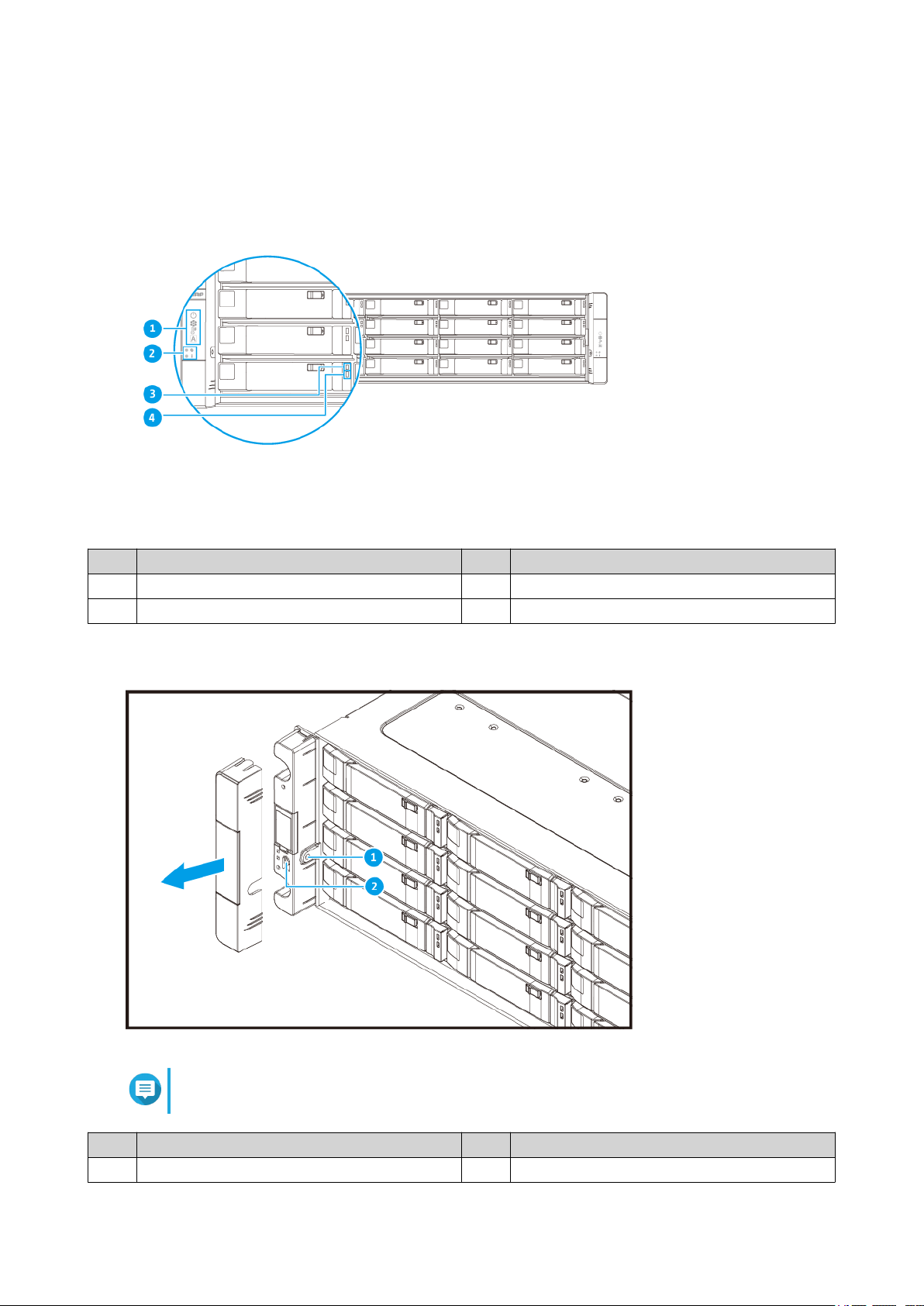
Front Panel
GM-1000 User Guide
No. Component No. Component
1 OLED panel 3 Drive status LED
2 Front panel LEDs 4 Drive activity LED
Front Panel Buttons
Note
Pull the panel cover to access the front panel buttons.
No. Component No. Component
1 OLED panel power button 2 Power button
Product Overview 8
Page 10
GM-1000 User Guide
Operation User Action Result
Power on NAS Press the power button The node powers on.
Tip
• QNAP recommends
powering on the
device from the rear
panel.
• System startup takes
10 to 15 minutes,
depending on the
number of installed
drives and connected
devices. Check the
rear panel LEDs to
determine the startup
status. For details,
see Rear Panel
LEDs.
Power on OLED display Press the OLED button. The OLED display powers on.
Power off OLED display Press the OLED button. The OLED display powers off.
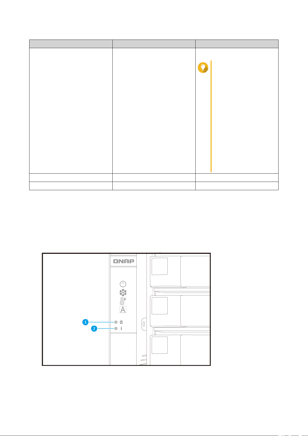
Front Panel LEDs
The front panel LEDs indicate system status and related information when the NAS is powered on. The
following LED information applies only when the drive is correctly installed and when the NAS is connected
to the network.
For details on the location of the LEDs, see Front Panel.
Product Overview 9
Page 11
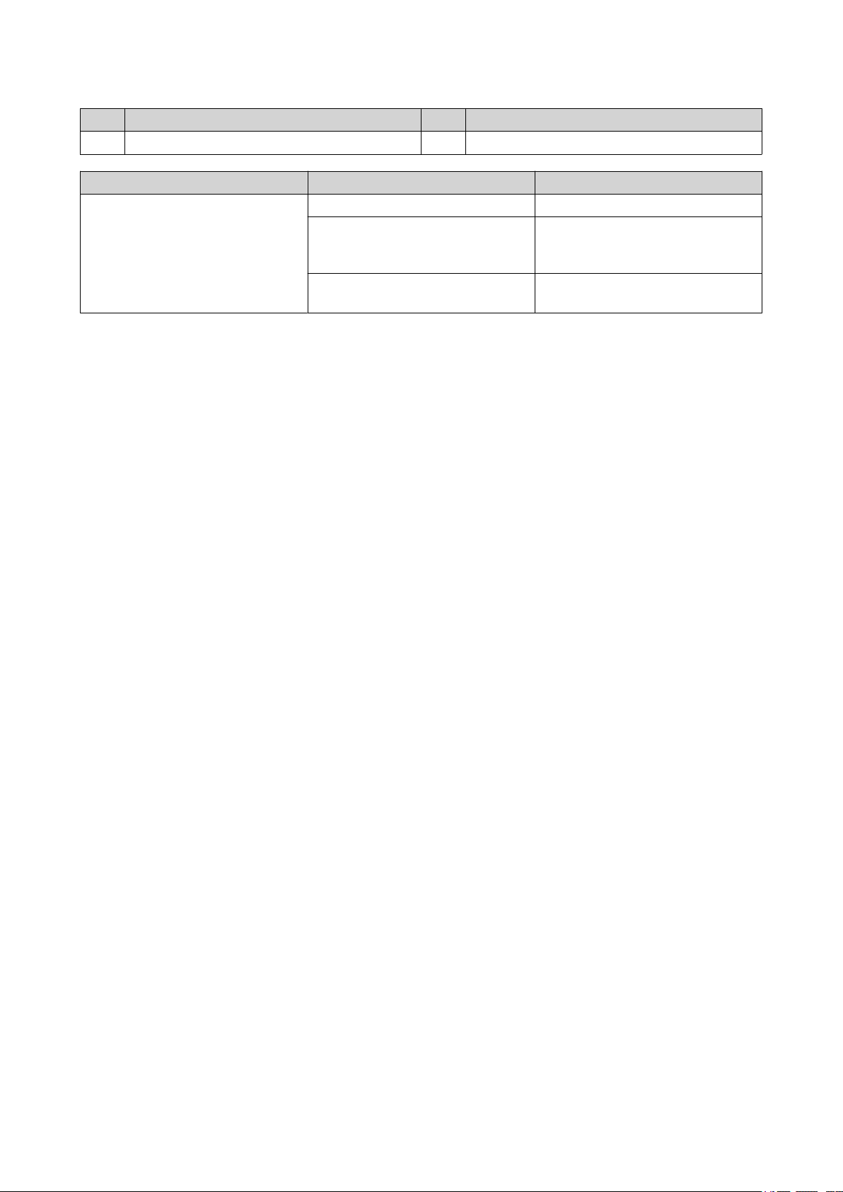
GM-1000 User Guide
No. Component No. Component
1 System power LED 2 System status LED
LED Status Description
System power Blue The node is powered on.
Flashing blue PSU errors or warnings (e.g. fan
error, one or more PSU is not
detected) were detected.
Off The power supply unit is
disconnected.
Product Overview 10
Page 12
LED Status Description
System status Flashes green and red alternately
every 0.5 seconds
Green The device is ready.
Flashes green every 0.5 seconds • The device is not configured.
Red • The drive is invalid.
GM-1000 User Guide
• The drive is being formatted.
• The device is being initialized.
• The operating system is being
updated.
• RAID rebuilding is in progress.
• Online RAID Capacity
Expansion is in progress.
• Online RAID Level Migration is
in progress.
• The drive is not formatted.
• The disk volume has reached
its full capacity.
• The disk volume is about to
reach its full capacity.
• The system fan is not
functioning.
• An error occurred when
accessing (read/write) the
data.
• A bad sector is detected on
the hard drive.
• The device is in degraded
read-only mode (two member
drives failed in RAID 5 or
RAID 6 but the data can still
be read).
• A hardware self-test error
occurred.
Flashes red every 0.5 seconds The device is in degraded mode
(one member drive failed in RAID
1, RAID 5, or RAID 6).
Off • The device is powered off.
Front Panel OLED Display
The OLED display shows the status of the nodes and main components.
• All drives are in standby
mode.
Product Overview 11
Page 13
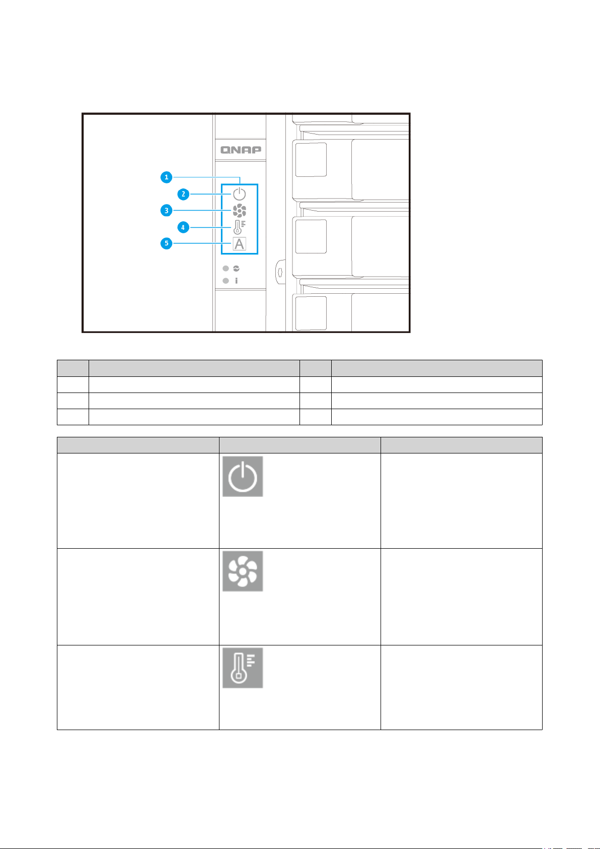
For details on the location of the OLED display, see Front Panel.
GM-1000 User Guide
No. Component No. Component
1 OLED panel 4 Temperature status
2 Node power status 5 Global ID
3 Fan status - -
Icon name Icon Description
Node power status • On: The node is powered on.
• Flashing: The node is booting
• Highlighting: The node is
shutting down
• Off: The node is off
Node fan status • On: The fan modules of the
node are operating normally
• Flashing: The fan modules of
the node are operating
incorrectly or are not installed
• Off: The node is off
Node temperature status • On: The temperature of the
node is normal
• Flashing: The temperature of
the node is too high or too low
• Off: The node is off
Product Overview 12
Page 14
GM-1000 User Guide
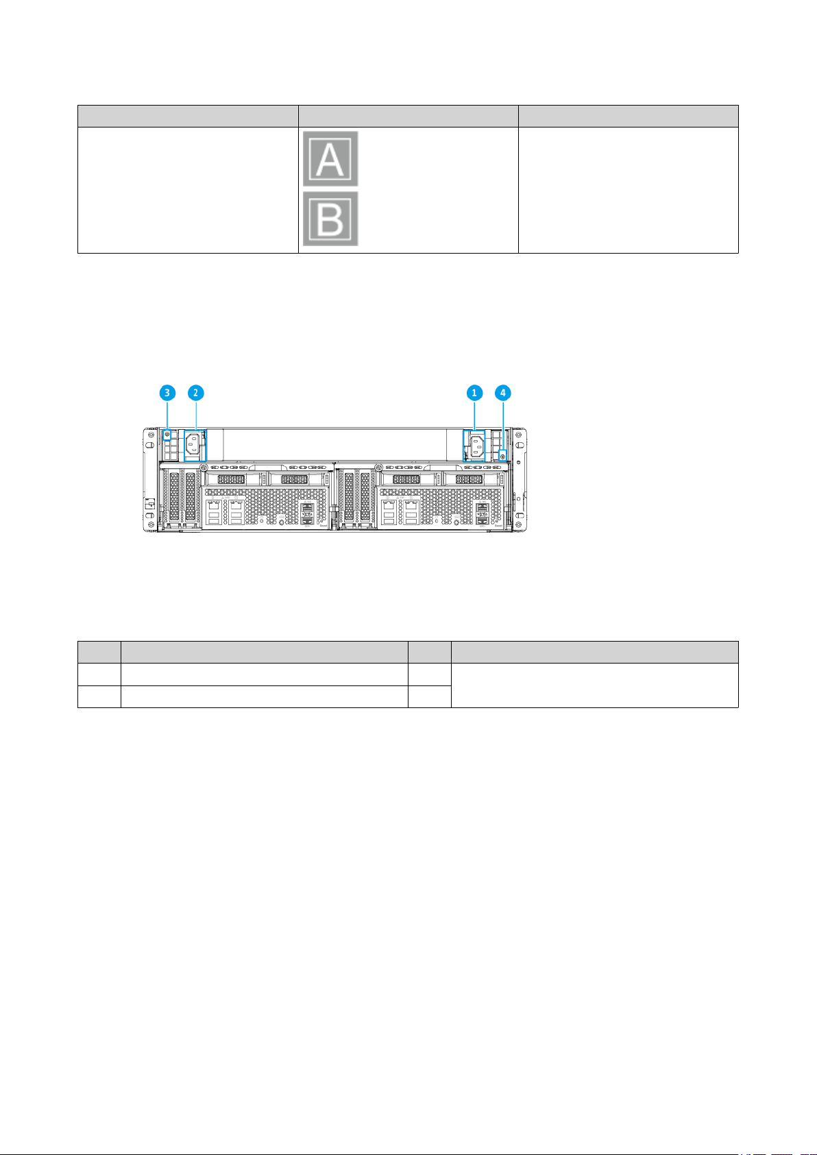
Icon name Icon Description
Node global ID • The global ID displays A or B
depending on the node
• The ID is always displayed
Power Supply Units
No. Component No. Component
1 Power supply unit 1 3 Power supply LED
2 Power supply unit 2 4
Product Overview 13
Page 15
GM-1000 User Guide
LED Status Description
Power supply Green The power supply unit is on
Flashing green (1 Hz) The power supply unit has +5VSB
standby supply power
Orange • The power supply unit is
failing
• OCP is activated
• OTP is activated
• OVP is activated
• UVP is activated
• The fans are failing
Flashing orange (1 Hz) • The temperature is too high
• The power is too strong
• The current is too high
• The fan is too slow
• The voltage is too low
Off The power supply unit is off
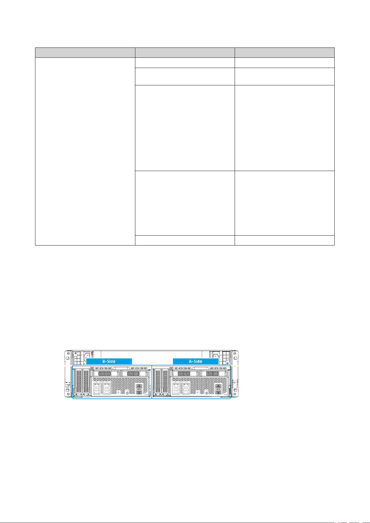
Node
This section provides information on components on the node. These components apply to both nodes.
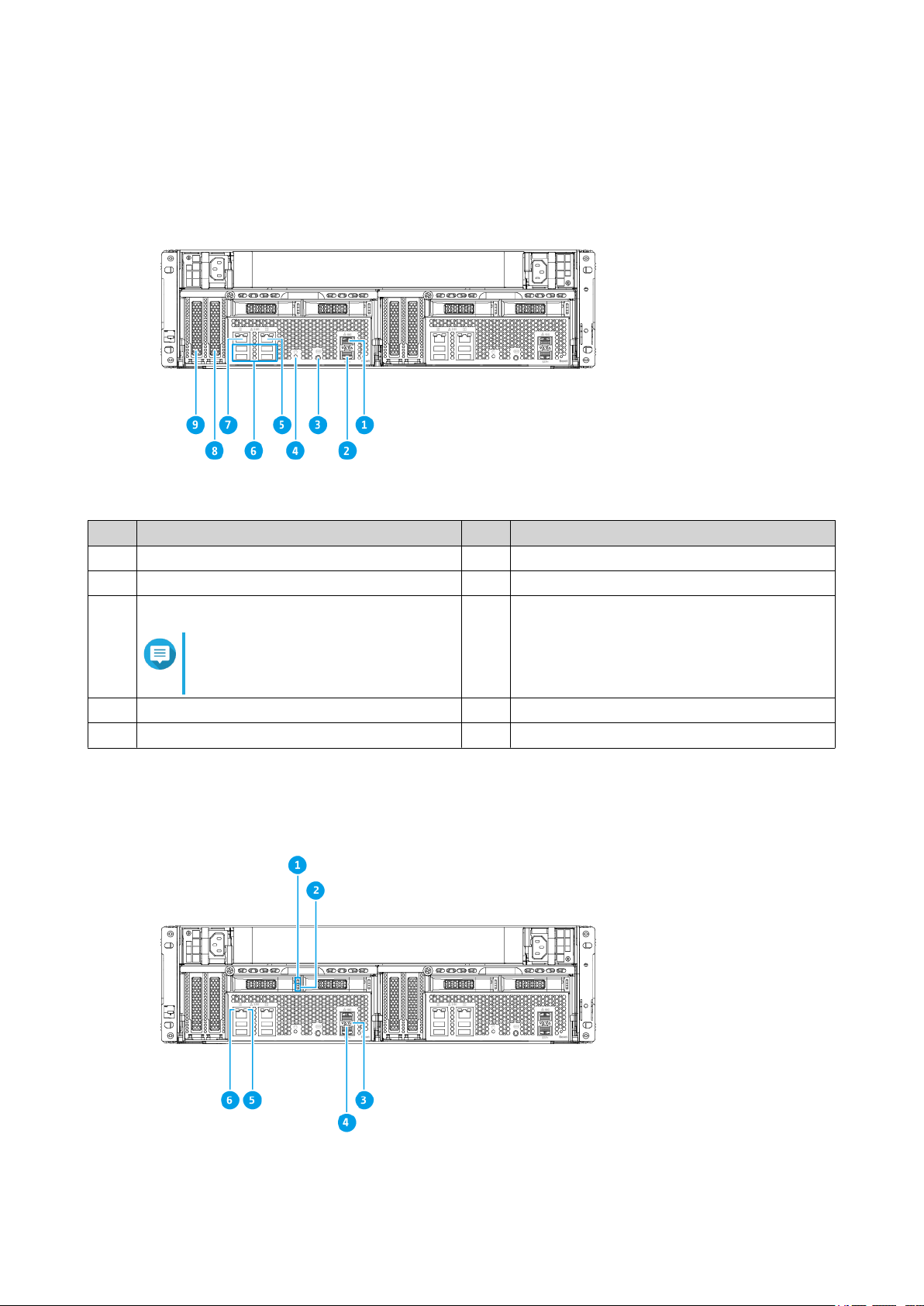
Rear Panel
Product Overview 14
Page 16
GM-1000 User Guide
No. Component No. Component
1 Ethernet port 1 (10GbE SFP+) 6 USB 3.2 Gen 2 Type-A ports
2 Ethernet port 2 (10GbE SFP+) 7 2.5 Gigabit Ethernet port 2
3 COM port
8 PCIe 3.0 x4 slot 1
Note
This port is for engineering
purposes only.
4 Power button 9 PCIe 3.0 x8 slot 2
5 2.5 Gigabit Ethernet port 1 - -
Rear Panel LEDs
Product Overview 15
Page 17

GM-1000 User Guide
No. Component No. Component
1 Drive status LED 4 10 Gigabit Ethernet speed LED
2 Drive activity LED 5 2.5 Gigabit Ethernet activity LED
3 10 Gigabit Ethernet activity LED 6 2.5 Gigabit Ethernet speed LED
LED Status Description
Drive status Green The drive is ready.
Red A drive read/write error occurred.
Flashes red every 5 seconds A drive is being located in the
operating system.
Off • No drive detected.
• The drive is not initialized.
Drive activity Green The drive is ready.
Flashes green The drive is being accessed.
Off No drive activity has been
detected.
10 Gigabit Ethernet port speed Green The network connection is
operating at 10 Gbps.
Off The network connection is not
operating at 10 Gbps.
10 Gigabit Ethernet port activity Orange The network link is active.
Flashing orange The data is being transmitted.
Off There is no network link.
2.5 Gigabit Ethernet port speed Green The network connection is
operating at 2.5 Gbps.
Orange • The network connection is
operating at 1 Gbps.
• The network connection is
operating at 100 Mbps.
Off The network connection is
operating at 10 Mbps.
2.5 Gigabit Ethernet port activity Orange A network connection has been
established.
Flashes orange The NAS is being accessed from
the network.
Off There is no network connection.
Storage Node Power Button
Operation User Action Result
Power on Press and hold the button for 1.5
seconds.
Power off Press and hold for 5 seconds. The node powers off.
• The OLED panel turns on.
• The node powers on.
Product Overview 16
Page 18

Operation User Action Result
Force power off Press and hold the button for 10
seconds.
Reset Button
Operation User Action Result
Basic system reset Press and hold the
button for 3 seconds.
The following settings are reset to default:
• System administrator password: MAC address of
adapter 1 without special characters. For example, if
the MAC address of adapter 1 is 11:22:33:44:55:66,
then the admin password will be 112233445566.
GM-1000 User Guide
The node powers off.
Warning
Use this method only
when the storage
controller is
unresponsive. This action
may result in data loss.
Advanced system
reset
Press and hold the
button for 15 seconds.
Tip
You can find the MAC address of adapter 1
using Qfinder Pro. A label attached to the
device also lists the address as MAC1.
• TCP/IP configuration:
• Obtain IP address settings automatically via
DHCP
• Disable jumbo frames
• If port trunking is enabled (multi-LAN models
only), the port trunking mode is reset to “Active
Backup (Failover)”.
• System port: 8080 (system service port)
• Security level: Low (Allow all connections)
• LCD panel password: (blank)
• VLAN: Disabled
The default factory settings are restored.
• To retrieve old data after an advanced system reset,
recreate the previous folder structure on the NAS.
Product Overview 17
Page 19

System Board
GM-1000 User Guide
No. Component No. Component
1 PCIe 3.0 x4 slot 1 5 Memory slot 4
2 PCIe 3.0 x8 slot 2 6 Memory slot 3
3 M.2 SSD slot 1 7 Memory slot 2
4 M.2 SSD slot 2 8 Memory slot 1
Drive Numbering
Front panel 3.5-inch drive bays
Product Overview 18
Page 20

Rear panel 2.5-inch drive bays
GM-1000 User Guide
Safety Information
The following instructions help ensure personal safety and environmental safety. Read these instructions
carefully before performing any operations.
General Instructions
• The device should be stored in a secure location with restricted access, controlled through the use of a
tool, lock and key, or any means of security.
• Only qualified, skilled, and authorized persons with knowledge of all restrictions, safety precautions,
and installation and maintenance procedures should have physical access to the device.
• To avoid potential injury or damage to components, ensure that the drives and other internal system
components have cooled before touching them.
• Observe electrostatic discharge (ESD) procedures to avoid potential injury or damage to components.
Power
• To reduce the risk of fire or electric shock, ensure that you only connect the power cord to a properly
grounded electrical outlet.
•
Devices with redundant power supply may have one or more power supply unit (PSU) cords. To avoid
serious injuries, a trained service technician must disconnect all PSU cords from the device before
installing or replacing system components.
System Battery
• To avoid potential battery explosion, causing injury or damage to components, ensure that you replace
the existing battery with a battery of the same type.
Product Overview 19
Page 21

GM-1000 User Guide
• Dispose of used batteries properly according to local regulations or the instructions of the battery
manufacturer.
Moving Parts
•
Moving fan blades: Keep your body parts away from moving fan blades while the device is connected
to a power source.
•
Moving components: Keep your body parts away from other moving components.
Installation Requirements
Category Item
Environment • Room temperature: 0˚C to 40˚C (32˚F to 104˚F)
• Non-condensing relative humidity: 5% to 95%
• Wet-bulb temperature: 27˚C (80.6˚F)
• Flat, anti-static surface without exposure to
direct sunlight, liquids, or chemicals
• Free from objects that may obstruct NAS
ventilation or apply pressure to the NAS or
power cord
Restricted access
• The NAS should be stored in a secure location
with restricted access, controlled through the use
of a tool, lock and key, or any means of security.
• Only qualified, trained, and authorized NAS
administrators with knowledge of all restrictions,
safety precautions, and installation and
maintenance procedures should have physical
access to the NAS.
Hardware and peripherals • Storage drives
For the list of compatible expansion cards, go to
https://www.qnap.com/compatibility.
• Network cable
Tools • Phillips #1 or #2 screwdriver
• Anti-static wrist strap
Product Overview 20
Page 22

Setting Up the NAS
Important
Read all safety requirements and information in Safety Information carefully before setting
up the NAS or installing NAS components.
1. Place your NAS device in an environment that meets the requirements.
For details, see Installation Requirements.
2. Install the drives. For details, see the following topics:
• Installing 3.5-inch Hard Drives on 3.5-inch Trays
• Installing 2.5-inch Hard Drives or Solid State Drives on 3.5-inch Trays
• Installing 2.5-inch Solid-State Drives on 2.5-inch Trays
• Installing M.2 Solid-State Drives on the System Board
For a list of compatible drives and expansion cards, go to https://www.qnap.com/en/compatibility/.
GM-1000 User Guide
3. Install expansion cards.
For details, see Installing Expansion Cards.
4. Install memory modules.
For details, see Replacing Memory Modules.
5. Connect the power cord and all applicable cables.
6. Power on the NAS.
For details, see Front Panel Buttons.
7. Install QuTS hero.
For details, see QuTS hero Installation.
8. Log on to QuTS hero.
Product Overview 21
Page 23

GM-1000 User Guide
3. Installation and Configuration
This chapter provides specific hardware and firmware installation and configuration steps.
Hardware Installation
This section provides information on removing or installing the nodes, drives, expansion cards, power supply
units, and memory modules.
Removing a Node
1. Power off the NAS.
2. Disconnect the power cord from the electrical outlet.
3. Disconnect all cables and external attachments.
4. Remove the node.
a. Loosen the screw.
b. Pull the handle to pull out the node.
Installation and Configuration 22
Page 24

GM-1000 User Guide
Installing a Node
1. Load the node into the NAS.
a. Insert the node into the chassis.
b. Push the handle up.
2. Tighten the screw.
Installation and Configuration 23
Page 25

GM-1000 User Guide
3. Connect all cables and external attachments.
4. Connect the power cord to the electrical outlet.
5. Power on the NAS.
Drive Installation
The GM-1000 is compatible with 3.5-inch hard drives, 2.5-inch hard drives, 2.5-inch sold-state drives, and M.
2 solid-state drives.
Installing 3.5-inch Hard Drives on 3.5-inch Trays
Warning
• Installing a drive deletes all data on the drive.
• Observe electrostatic discharge (ESD) procedures to avoid damage to components.
•
Moving fan blades: Keep your hands and other body parts away from moving fan
blades.
•
Other moving components: Keep your hands and other body parts away from other
moving components.
1. Power off the NAS.
Installation and Configuration 24
Page 26

2. Remove the drive tray.
a. Slide the lock to the left.
GM-1000 User Guide
b. Push the button to release the tray handle.
c. Pull the tray out.
3. Install a drive on the tray.
a. Place the drive on the tray so that the holes on the sides of the drive are aligned with the holes on
the sides of the tray.
b. Attach the screws.
Installation and Configuration 25
Page 27

GM-1000 User Guide
4. Load the tray into the bay.
a. Insert the tray into the bay.
b. Push the handle.
c. Slide the lock to the right.
5. Power on the NAS.
Installation and Configuration 26
Page 28

Installing 2.5-inch Hard Drives or Solid State Drives on 3.5-inch Trays
Warning
• Installing a drive deletes all data on the drive.
• Observe electrostatic discharge (ESD) procedures to avoid damage to components.
•
Moving fan blades: Keep your hands and other body parts away from moving fan
blades.
•
Other moving components: Keep your hands and other body parts away from other
moving components.
GM-1000 User Guide
1. Power off the NAS.
2. Remove the drive tray.
a. Slide the lock to the left.
b. Push the button to release the tray handle.
c. Pull the tray out.
Installation and Configuration 27
Page 29

GM-1000 User Guide
3. Install a drive on the tray.
a. Place the drive on the tray so that the holes on the bottom of the drive are aligned with the holes
on the bottom of the tray.
b. Attach the screws.
4. Load the tray into the bay.
a. Insert the tray into the bay.
Installation and Configuration 28
Page 30

b. Push the handle.
GM-1000 User Guide
c. Slide the lock to the right.
5. Power on the NAS.
Installing 2.5-inch Solid-State Drives on 2.5-inch Trays
Warning
• Installing a drive deletes all data on the drive.
• Observe electrostatic discharge (ESD) procedures to avoid damage to components.
•
Moving fan blades: Keep your hands and other body parts away from moving fan
blades.
•
Other moving components: Keep your hands and other body parts away from other
moving components.
1. Power off the NAS.
2. Remove the drive tray.
a. Pull the handle to release the tray.
b. Pull the tray out.
Installation and Configuration 29
Page 31

GM-1000 User Guide
3. Install a drive on the tray.
a. Place the drive on the tray so that the holes on the bottom of the drive are aligned with the holes
on the bottom of the tray.
b. Attach the screws.
4. Load the tray into the bay.
a. Insert the tray into the bay.
b. Push the handle.
Installation and Configuration 30
Page 32

GM-1000 User Guide
5. Power on the NAS.
Installing M.2 Solid-State Drives on the System Board
The GM-1000 has two M.S SSD slots on the system board. For a list of compatible M.S. SSDs, go to http://
www.qnap.com/compatibility.
Warning
• Only qualified personnel should perform the following steps. Failure to follow
instructions can result in serious injury or death.
• Observe electrostatic discharge (ESD) procedures to avoid damage to components.
•
Moving fan blades: Keep your hands and other body parts away from moving fan
blades.
•
Other moving components: Keep your hands and other body parts away from other
moving components.
1. Remove the node.
For details, see Removing a Node.
2. Install the M.2 SSD.
a. Insert the M.2 SSD into the slot.
Installation and Configuration 31
Page 33

GM-1000 User Guide
b. Attach the screw.
3. Install the node.
For details, see Installing a Node.
Installing Expansion Cards
The GM-1000 supports selected expansion cards, some of which require QNAP PCIe brackets. QNAPbranded expansion cards purchased from the company website are shipped with the brackets necessary to
fit the GM-1000.
Warning
• Only qualified personnel should perform the following steps. Failure to follow instructions
can result in serious injury or death.
Installation and Configuration 32
Page 34

GM-1000 User Guide
• Observe electrostatic discharge (ESD) procedures to avoid damage to components.
•
Moving fan blades: Keep your hands and other body parts away from moving fan blades.
•
Other moving components: Keep your hands and other body parts away from other
moving components.
1. Check the expansion cards and brackets supported by your model on the QNAP website.
a. Go to www.qnap.com/compatibility.
b. Click Search by NAS.
c. Specify the number of bays and the specific model of your NAS.
d. Under Category, select the component or device type.
e. Locate a specific component or device model in the list.
f. Optional: Click the corresponding Note icon to view more information.
2. Remove the node.
For details, see Removing a Node.
3. Remove the PCIe cover.
a. Remove the screw that secures the cover to the bracket.
b. Pull the cover away from the slot.
Installation and Configuration 33
Page 35

4. Optional: Attach the QNAP bracket to the expansion card.
a. Remove all screws of the existing bracket.
GM-1000 User Guide
b. Carefully pull the bracket away from the card.
c. Attach the QNAP bracket to the card using the same screws.
d. Verify that the bracket does not move.
5. Install the expansion card.
a. Hold the card by the edges.
b. Insert the card into the slot.
c. Attach the screw.
Installation and Configuration 34
Page 36

GM-1000 User Guide
6. Install the node. For details, see Installing a Node.
Replacing Memory Modules
Use only QNAP memory modules to maintain system performance and stability. You can purchase QNAP
memory modules from authorized resellers.
Use only QNAP modules of the same type and capacity to maintain system performance and stability. You
can purchase QNAP memory modules from authorized resellers.
Important
For best results, QNAP recommends installing modules in pairs.
• Ensure that each pair uses identical modules.
• Install the pairs in sequence and follow the assigned slots for each pair.
• When installing only one module, use slot 1.
For details on slot numbering, see System Board.
Module Pair Slot Number
First pair Slots 2 and 4
Second pair Slots 1 and 3
Memory Slot Channel
1 Channel A, DIMM1
2 Channel A, DIMM2
3 Channel B, DIMM1
4 Channel B, DIMM2
Warning
Installation and Configuration 35
Page 37

• Only qualified personnel should perform the following steps. Failure to follow
instructions can result in serious injury or death.
• Observe electrostatic discharge (ESD) procedures to avoid damage to components.
•
Moving fan blades: Keep your hands and other body parts away from moving fan
blades.
•
Other moving components: Keep your hands and other body parts away from other
moving components.
1. Remove the node.
For details, see Removing a Node.
GM-1000 User Guide
2. Optional: Remove an existing module.
a. Push the retention clips outward simultaneously to release the module.
Warning
Attempting to remove a module that is not completely released may damage the module and
the motherboard.
b. Hold the module by the edges.
c. Carefully slide the module out of the slot.
3. Install a new module.
a. Align the notch with the ridge in the slot.
Installation and Configuration 36
Page 38

GM-1000 User Guide
b. Insert the module into the slot.
c. Verify that the metal connectors are completely inserted into the slot.
d. Carefully press down on the module until the retention clips lock the module into place.
4. Install the node.
For details, see Installing a Node.
5. Verify that the module is recognized by the NAS.
a. Log on to QuTS as administrator.
b. Go to Control Panel > System > System Status > Hardware Information .
c. Check the value for Total memory.
Hot-swapping Redundant Power Supply Units
Warning
The NAS may have one or more power supply unit (PSU) cords. To avoid serious injuries,
a trained service technician must disconnect all PSU cords before installing or replacing
system components.
1. Power off the node.
2. Disconnect the power cord from the electrical outlet and the PSU that you are replacing.
3. Firmly press the latch toward the handle and then pull the PSU out.
Installation and Configuration 37
Page 39

GM-1000 User Guide
4. Insert the new PSU.
5. Connect the power cord to the PSU and the electrical outlet.
6. Power on the storage controller.
Installing Expansion Units
The GM-1000 supports SAS expansion units, SATA expansion units, SATA JBOD expansion units, and USB
expansion units. For details, see table below.
You can purchase storage expansion accessories from QNAP or an authorized reseller.
For details, go to https://shop.qnap.com/.
Installation and Configuration 38
Page 40

GM-1000 User Guide
For the list of compatible expansion units and the maximum number of applicable expansion units, go to
http://www.qnap.com/go/compatibility-expansion.
Expansion Unit Model Description Required Accessories
REXP-1620U-RP • Uses a SAS 12 Gbps
(SFF-8644) interface
• SAS-12G2E storage
expansion card
• Supports SAS/SATA
HDD/SSD
REXP-1220U-RP • Uses a SAS 12 Gbps
(SFF-8644) interface
• Supports SAS/SATA
HDD/SSD
REXP-1610U-RP • Uses a SAS 6 Gbps
(SFF-8644) interface
• Supports SATA/HDD/SSD
REXP-1210U-RP • Uses a SAS 6 Gbps
(SFF-8644) interface
• Supports SATA/HDD/SSD
TL-D400S • Uses a SAS 6 Gbps
(SFF-8088) interface
• Supports SATA/HDD/SSD
TL-D800S • Uses a SAS 6 Gbps
(SFF-8088) interface
• mini-SAS SFF-8644 cable
• RAIL-A03-57
• SAS-12G2E storage
expansion card
• mini-SAS SFF-8644 cable
• RAIL-A03-57
• SAS-12G2E storage
expansion card
• mini-SAS SFF-8644 cable
• RAIL-A03-57
• SAS-12G2E storage
expansion card
• mini-SAS SFF-8644 cable
• RAIL-A03-57
• 1 x SFF-8088 connector cable
• QXP-400eS-A1164 host bus
adapter
• 2 x SFF-8088 connector
cables
• Supports SATA/HDD/SSD
TL-D1600S • Uses a SAS 6 Gbps
(SFF-8088) interface
• Supports SATA/HDD/SSD
TL-R400S • Uses a SAS 6 Gbps
(SFF-8088) interface
• Supports SATA/HDD/SSD
TL-R1200S-RP • Uses a SAS 6 Gbps
(SFF-8088) interface
• Supports SATA/HDD/SSD
• QXP-800eS-A1164 host bus
adapter
• 4 x SFF-8088 to SFF-8644
connector cables
• QXP-1600eS host bus adapter
• 1 x SFF-8088 connector cable
• QXP-400eS-A1164 host bus
adapter
• RAIL-B02
• 3 x SFF-8088 to SFF-8644
connector cables
• QXP-1600eS host bus adapter
• RAIL-B02
Installation and Configuration 39
Page 41

Expansion Unit Model Description Required Accessories
TR-002 • Uses a USB 3.2 Gen 2 Type-C
interface
USB 3.2 Gen 2 Type-A to Type-C
cable
• Supports SATA drives
TR-004 • Uses a USB 3.2 Gen 1 Type-C
interface
USB 3.2 Gen 2 Type-A to Type-C
cable
• Supports SATA drives
TR-004U • Uses a USB 3.2 Gen 1 Type-C
interface
• USB 3.2 Gen 1 Type-A to
Type-C cable
GM-1000 User Guide
• Supports SATA drives
TL-D800C • Uses a USB 3.2 Gen 2 Type-C
interface
• Supports SATA drives
TL-R1200C-RP • Uses a USB 3.2 Gen 2 Type-C
interface
• Supports SATA drives
Connecting SAS Expansion Units
1. Install a storage expansion card on the PCIe slot.
For details, see Installing Expansion Cards.
2. Connect the expansion units to the NAS using the following topology.
• RAIL-B02
USB 3.2 Gen 2 Type-A to Type-C
cable
• USB 3.2 Gen 2 Type-A to
Type-C cable
• RAIL-B02
3. Power on the expansion units.
Installation and Configuration 40
Page 42

4. Verify that the expansion units are recognized by the NAS.
a. Log on to QuTS hero as administrator.
b. Go to Main Menu > Storage & Snapshots > Overview > Storage > System .
c. Verify that the expansion units are listed.
Connecting SATA Expansion Units
1. Power off the NAS.
2. Install a host bus adapter on the PCIe slot.
Note
The QNAP QXP host bus adapter is required for connecting the SATA JBOD enclosure to a
host device. Third-party host bus adapters are not compatible with QNAP JBOD enclosures.
For details, see Installing Expansion Cards.
3. Connect the expansion units to the NAS using the following topology.
GM-1000 User Guide
4. Power on the SATA JBOD expansion units.
5. Power on the NAS.
6. Verify that the expansion units are recognized by the NAS.
a. Log on to QuTS hero as administrator.
Installation and Configuration 41
Page 43

GM-1000 User Guide
b. Go to Main Menu > Storage & Snapshots > Overview > Storage > System .
c. Verify that the expansion units are listed.
Connecting USB Expansion Units
To connect the GM-1000 to USB expansion units, USB Type-A to USB Type-C cables are required. For
required accessories details, see Installing Expansion Units.
1. Connect the expansion unit to the NAS.
a. Connect the USB cable to a USB 3.2 Gen 1 Type-A port on the NAS.
2. Power on the expansion units.
3. Verify that the expansion units are recognized by the NAS.
a. Log on to QuTS hero as administrator.
b. Go to Main Menu > Storage & Snapshots > Overview > Storage > System .
c. Verify that the expansion units are listed.
QuTS hero Installation
The GM-1000 uses the QNAP QuTS hero operating system. You can install QuTS hero using any of the
following methods:
Installation and Configuration 42
Page 44

Method Description Requirements
Qfinder Pro installation
(Recommended)
If the NAS is connected to your
local area network, you can do the
following:
GM-1000 User Guide
• Computer
• Network cable
• Locate the NAS using Qfinder
Pro.
• Complete the steps in the
Smart Installation Guide
wizard.
For details, see Installing QuTS
hero Using Qfinder Pro.
Cloud installation If the NAS is connected to the
internet, you can do the following:
• Scan the QR code on the
NAS.
• Specify the Cloud Key.
• Log into your myQNAPcloud
account.
For details, see Installing QuTS
hero Using the Cloud Key
Installing QuTS hero Using Qfinder Pro
• Qfinder Pro installer
• Computer or mobile device
• myQNAPcloud account
• Cloud Key
Warning
Installing QuTS hero deletes all data on the drives. Back up your data before proceeding.
Note
You can revert to the QTS operating system anytime. For details, see QuTS hero user
guide.
1. Power on the NAS.
2. Connect the NAS to your local area network.
3. Run Qfinder Pro on a computer that is connected to the same local area network.
Note
To download Qfinder Pro, go to https://www.qnap.com/utilities.
4. Locate the NAS in the list and then double-click the name or IP address.
The Smart Installation Guide opens in the default web browser.
5. Click Start Smart Installation Guide.
6. Specify the following information.
• NAS name: Specify a name with 1 to 14 characters. The name supports letters (A to Z, a to z),
numbers (0 to 9), and hyphens (-), but cannot end with a hyphen.
Installation and Configuration 43
Page 45

• Password: Specify an administrator password with 1 to 64 characters. The password supports all
ASCII characters.
7. Click Next.
8. Specify the time zone, date, and time.
Tip
QNAP recommends connecting to an NTP server to ensure that the NAS follows the
Coordinated Universal Time (UTC) standard.
9. Click Next.
10. Select Obtain an IP address automatically (DHCP).
11. Click Next.
12. Select the types of devices that you will use to access shared folders on the NAS.
13. Click Next.
14. Review the settings.
GM-1000 User Guide
15. Click Apply.
A confirmation message appears.
Warning
Clicking Confirm deletes all data on the drive before installing QuTS hero.
16. Click Confirm.
QuTS hero is installed.
Installing QuTS hero Using the Cloud Key
Warning
Installing QuTS hero deletes all data on the drives. Back up your data before proceeding.
Note
You can revert to QTS operating system anytime. For details, see QuTS hero user guide.
1. Power on the NAS.
2. Connect the NAS to the internet.
3. Go to the QNAP Cloud Installation page using one of the following methods:
• On your computer, go to https://install.qnap.com/.
• Scan the QR code on the NAS using a mobile device.
The web page lists all the uninitialized QNAP NAS devices on the local network.
4. Find your NAS from the list and then click Initialize.
Note
If your NAS is not listed, follow the instructions on the web page to specify the Cloud Key on the
NAS.
Installation and Configuration 44
Page 46

The installation wizard opens in the default web browser.
5. Create an account or sign in to myQNAPcloud.
Note
You must return to this page to complete the installation after creating an account.
6. Specify the myQNAPcloud device name for the NAS.
Note
• The myQNAPcloud device name is used when remotely accessing the NAS.
• For security purposes, the myQNAPcloud Link remote connection service will be disabled
on your NAS after initialization. You can enable it by connecting to QuTS hero through LAN
and then installing myQNAPcloud Link.
7. Click Next.
The Smart Installation Guide opens in the default web browser.
8. Click Start Smart Installation Guide.
GM-1000 User Guide
9. Specify the following information.
• NAS name: Specify a name with 1 to 14 characters. The name supports letters (A to Z, a to z),
numbers (0 to 9), and hyphens (-), but cannot end with a hyphen.
• Password: Specify an administrator password with 1 to 64 characters. The password supports all
ASCII characters.
10. Click Next.
11. Specify the time zone, date, and time.
Tip
QNAP recommends connecting to an NTP server to ensure that the NAS follows the
Coordinated Universal Time (UTC) standard.
12. Click Next.
The Configure the network settings screen appears.
13. Select Obtain an IP address automatically (DHCP).
You can also choose the Static IP Address configuration option to meet your networking needs. You
can only apply one network configuration method.
14. Click Next.
The Cross-platform file transfer service screen appears.
15. Select the types of devices that you will use to access shared folders on the NAS.
16. Click Next.
The Summary screen appears.
17. Review the settings.
18. Click Apply.
A confirmation message appears.
Installation and Configuration 45
Page 47

Warning
Clicking Confirm deletes all data on the drive before installing QuTS hero.
19. Click Confirm.
QuTS hero is installed.
GM-1000 User Guide
Installation and Configuration 46
Page 48

GM-1000 User Guide
4. Troubleshooting
This chapter describes basic troubleshooting information.
Forcing Qfinder Pro or myQNAPcloud to Locate the NAS
If Qfinder Pro or myQNAPcloud is unable to locate the NAS during QuTS hero installation, the drives or data
may be faulty.
1. Power off the NAS.
2. Remove all drives.
3. Power on the NAS.
4. Locate the NAS using Qfinder Pro or myQNAPcloud.
5. Reinsert the drives.
6. Continue with the QuTS hero installation.
Hot-swapping Failed Drives
The NAS supports hot-swapping of drives in the following situations.
• RAID 1: One member drive fails
• RAID 5: One member drive fails
• RAID 6: One or two member drives fail
1. Log on to QuTS hero.
2. Go to Main Menu > Storage & Snapshots > Storage > Disks/VJBOD .
3. Locate the failed drive.
4. Prepare a new hard drive with a capacity that is the same as or larger than the failed hard drive.
5. Remove the failed drive from the NAS.
6. Wait for 20 seconds or until the NAS beeps twice.
7. Remove the failed drive from the drive tray.
8. Insert the new drive into the drive tray.
9. Install the new drive.
The NAS beeps twice.
10. Go to Main Menu > Storage & Snapshots > Storage Space .
11. Locate the volume that contains the new drive and then verify that the status is Rebuilding.
Support and Other Resources
QNAP provides the following resources:
Troubleshooting 47
Page 49

GM-1000 User Guide
Resource URL
Documentation https://docs.qnap.com
Compatibility List https://www.qnap.com/compatibility/
NAS Migration Compatibility https://www.qnap.com/en/nas-migration
Expansion Unit Compatibility http://www.qnap.com/go/compatibility-expansion
Service Portal https://service.qnap.com
Product Support Status https://www.qnap.com/product/eol.php
Downloads https://download.qnap.com
Community Forum https://forum.qnap.com
QNAP Accessories Store https://shop.qnap.com/
Troubleshooting 48
Page 50

GM-1000 User Guide
5. Glossary
Cloud Key
Unique 8-digit code assigned to each NAS device
myQNAPcloud Link
Enables you to access the NAS over the internet without configuring complex port forwarding settings
myQNAPcloud
Provides various remote access services such as DDNS and myQNAPcloud Link
myQNAPcloud ID
Email address that was used to register for a myQNAPcloud account
Qfinder Pro
QNAP utility that lets you locate and access QNAP NAS devices in your local area network
QuTS hero
QNAP NAS operating system featuring ZFS file system
Glossary 49
Page 51

GM-1000 User Guide
6. Notices
This chapter provides information about warranty, disclaimers, licensing, and federal regulations.
Limited Warranty
QNAP offers limited warranty service on our products. Your QNAP-branded hardware product is warranted
against defects in materials and workmanship for a period of one (1) year or more from the date printed on
the invoice. ("Warranty Period"). Please review your statutory rights at www.qnap.com/warranty, which may
be amended from time to time by QNAP in its discretion.
Disclaimer
Information in this document is provided in connection with products of QNAP Systems, Inc. (the "QNAP").
No license, express or implied, by estoppels or otherwise, to any intellectual property rights is granted by this
document. Except as provided in QNAP's terms and conditions of sale for such products, QNAP assumes no
liability whatsoever, and QNAP disclaims any express or implied warranty, relating to sale and/or use of
QNAP products including liability or warranties relating to fitness for a particular purpose, merchantability, or
infringement of any patent, copyright or other intellectual property right.
QNAP products are not intended for use in medical, life saving, life sustaining, critical control or safety
systems, or in nuclear facility applications.
In no event shall QNAP’s liability exceed the price paid for the product from direct, indirect, special,
incidental, or consequential damages resulting from the use of the product, its accompanying software, or its
documentation. QNAP makes no warranty or representation, expressed, implied, or statutory, with respect to
its products or the contents or use of this documentation and all accompanying software, and specifically
disclaims its quality, performance, merchantability, or fitness for any particular purpose. QNAP reserves the
right to revise or update its products, software, or documentation without obligation to notify any individual or
entity.
Back up the system periodically to avoid any potential data loss is recommended. QNAP disclaims any
responsibility of all sorts of data loss or recovery.
Should you return any components of the package of QNAP products such as NAS (Network Attached
Storage) for refund or maintenance, make sure they are carefully packed for shipping. Any form of damages
due to improper packaging will not be compensated.
All the features, functionality, and other product specifications are subject to change without prior notice or
obligation. Information contained herein is subject to change without notice.
Further, the ® or ™ symbols are not used in the text.
BSMI Notice
警告使用者:這是甲類的資訊產品,在居住的環境中使用時,可能會造成射頻干擾,在
這種情況下,使用者會被要求採取某些適當的對策。
Notices 50
Page 52

CE Notice
This QNAP NAS complies with CE Compliance Class A.
FCC Notice
FCC Class A Notice
This device complies with Part 15 of the FCC Rules. Operation is subject to the
following two conditions:
GM-1000 User Guide
1. This device may not cause harmful interference.
2. This device must accept any interference received, including interference that may cause undesired
operation.
Note
This equipment has been tested and found to comply with the limits for a Class A digital
device, pursuant to Part 15 of the FCC Rules. These limits are designed to provide
reasonable protection against harmful interference when the equipment is operated in a
commercial environment. This equipment generates, uses, and can radiate radio
frequency energy, and if not installed and used in accordance with the instruction manual,
may cause harmful interference to radio communications. Operation of this equipment in a
residential area is likely to cause harmful interference, in which case the user will be
required to correct the interference at his own expense.
Important
Any modifications made to this device that are not approved by QNAP Systems, Inc. may
void the authority granted to the user by the FCC to operate this equipment.
SJ/T 11364-2006
本产品符合中国 RoHS 标准。以下表格标示此产品中某有毒物质的含量符合中国
RoHS 标准规定的限量要求。
本产品上会附有”环境友好使用期限”的标签,此期限是估算这些物质”不会有泄漏或突变”的年限。本产品
可能包含有较短的环境友好使用期限的可替换元件,像是电池或灯管,这些元件将会单独标示出来。
Notices 51
Page 53

GM-1000 User Guide
部件名称 有毒有害物质或元素
铅
(Pb)
汞
(Hg)
镉
(Cd)
六价铬
(CR(VI))
多溴联苯
(PBB)
多溴二苯醚
(PBDE)
壳体 0 0 0 0 0 0
显示 0 0 0 0 0 0
印刷电路板 0 0 0 0 0 0
金属螺帽 0 0 0 0 0 0
电缆组装 0 0 0 0 0 0
风扇组装 0 0 0 0 0 0
电力供应组装 0 0 0 0 0 0
电池 0 0 0 0 0 0
O: 表示该有毒有害物质在该部件所有物质材料中的含量均在 SJ/T11363-2006 标准规定的限量要求以下。
X: 表示该有毒有害物质至少在该部件的某一均质材料中的含量超出 SJ/T11363-2006 标准规定的限量要求。
VCCI Notice
この装置は、クラス A 情報技術装置です。この装置を家庭環境で使用すると電波
妨害を引き起こすことがあります。この場合には使用者が適切な対策を講ずるよう要求されることがありま
す。
VCCI–A
Notices 52
 Loading...