


HOSS Series (Rev B)
Smart Series
Large Wall Heater
Installation, Operation & Maintenance Instructions
READ CAREFULLY - This manual provides instructions for the correct installation, safe use, and care of this product. Special attention should be directed to the warnings provided below which identify certain precautions and special instructions for safe and efficient installation and use. Studying these instructions first may save you considerable time and money later and keep your installation time to a minimum. If you are not familiar with electricity or feel uncomfortable in working with electricity, refer the installation of this product to a licensed electrician or qualified person.
Table 1. Specifications |
|
|
|
|
|
|
|
|
|
|
MIN. SUPPLY |
MODEL |
VOLTS |
PHASE |
WATTS |
AMPS |
WIRE GAUGE |
HOSS4008 |
208 |
1 |
1800-4000 |
19.2 |
10 |
HOSS4004 |
240 |
1 |
1800-4000 |
16.7 |
10 |
HOSS4007 |
277 |
1 |
1800-4000 |
14.4 |
12 |
IMPORTANT INSTRUCTIONS
WARNING !
WHEN USING ELECTRIC APPLIANCES, BASIC PRECAUTIONS SHOULD ALWAYS BE FOLLOWED TO REDUCE THE RISK OF FIRE, ELECTRIC SHOCK, AND INJURY TO PERSONS, INCLUDING THE FOLLOWING:
1.Read all instructions before installing or using this heater.
2.This heater is hot when in use. To avoid burns, do not let bare skin touch hot surfaces. Keep combustible materials, such as furniture, pillows, bedding, papers, clothes, curtains, etc. at least 3 feet (0.9 m) from the front of the heater.
3.Extreme caution is necessary when any heater is used by or near children or invalids and whenever the heater is left operating and unattended.
4.Do not operate any heater after it malfunctions. Disconnect power at service panel and have heater inspected by a qualified electrician before using.
5.Do not use outdoors.
6.To disconnect heater, turn controls to OFF, and turn OFF power to heater circuit at main disconnect panel.
7.Do not insert or allow foreign objects to enter any ventilation or exhaust opening as this may cause an electric shock, fire, or damage to the heater.
8.To prevent a possible fire, do not block air intake or exhaust in any manner.
9.A heater has hot and arcing or sparking parts inside. Do not use it in areas where gasoline, paint, or flammable liquids are used or stored.
10.Use this heater only as described in this manual. Any other use not recommended by the manufacturer may cause fire, electric shock, or injury to persons.
11.This heater is provided with a red alarm light that will illuminate ONLY if the heater has turned off as a result of overheating. If you see the light on, immediately turn the heater OFF and inspect for any objects on or adjacent to the heater that may have blocked the airflow or otherwise caused high temperatures to have occurred. DO NOT OPERATE THE
HEATER WITH THE ALARM LIGHT ILLUMINATING.
12.This heater is intended for comfort heating applications and not intended for use in special environments. Do not use in damp or wet locations such as marine or greenhouse or in areas where corrosive or chemical agents are present.
13.When installing, see INSTALLATION INSTRUCTIONS for additional warnings and precautions.
14.For safe and efficient operation, and to extend the life of your heater, keep your heater clean - See MAINTENANCE INSTRUCTIONS.
SAVE THESE INSTRUCTIONS
PPD 35950 |
06/12 |
5200-11092-000 |
INSTALLATION
INSTRUCTIONS
To prevent a possible fire, injury to persons or damage to the heater, adhere to the following:
1.Disconnect all power coming to heater at main service panel before wiring or servicing.
2.All wiring procedures and connections must be in accordance with the National and Local Codes having jurisdiction and the heater must be grounded.
3.Verify the power supply voltage coming to heater matches the ratings as shown on the heater nameplate.
CAUTION: ENERGIZING HEATER AT A VOLTAGE GREATER THAN THE VOLTAGE PRINTED ON THE NAMEPLATE WILL DAMAGE THE HEATER AND VOID THE WARRANTY AND COULD CAUSE A FIRE.
4.CAUTION - High temperature, risk of fire, keep electrical cords, drapery, furnishings, and other combustibles at least 3 feet (0.9 m) from front of heater. Do not install heater behind doors, below towel racks, or in an area where it is subject to being blocked by furniture, curtains or storage materials. Hot air from the heater may damage certain fabrics and plastics.
5.To reduce the risk of fire, do not store or use gasoline or other flammable vapors and liquids in the vicinity of the heater.
6.For wall mounting only with air discharge downward. Do NOT install in floor, ceiling, upside down (air discharge upward), or sideways.
7.The following minimum clearances must be maintained: Bottom of heater to floor - 12” (305 mm).
Sides of heater to adjacent wall - 12” (305 mm). Top of heater to ceiling - 36” (915 mm).
8.Do not operate the heater without the grille installed.
9.Do not use this heater for dry out as the paint, plaster, sawdust and drywall sanding dust will permanently damage the heater and must be kept out of the heater.
The heater is designed for recessed installation in 2” x 4”
(50 mm x 101 mm) studs or larger wall sections using the back box provided. The heater may be wired with standard building wire (60°C). Refer to “Specifications” and heater nameplate for correct supply voltage and wire size.
NOTE: The optimum mounting height for this heater is 18” to 24” (450 mm to 600 mm) from floor to bottom of back box. DO NOT install closer than 12” (305 mm) from the floor.
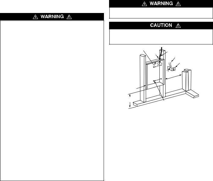
Installation of Back Box in New Construction
TO PREVENT HAZARD OF FIRE OR ELECTRICAL SHOCK, DO NOT INSTALL WITHOUT BACK BOX.
TO PREVENT POSSIBLE DAMAGE TO POWER WIRING, USE ONLY THE KNOCKOUTS PROVIDED IN BACK BOX WITH LISTED CABLE CLAMP OR BUSHING.
Ground screw |
Cable |
Power supply cable |
|
clamp |
|
|
Lead wires (Blue) |
|
|
|
|
|
|
ON/OFF switch bracket |
|
|
with switch and leads |
12” Min.
(305 mm)
Back Box
12” Min.
(305 mm) Nail or screw (2 each side)
Figure 1 - Locating Back Box in New Construction
NOTE: If the finished wall surface is already up, follow instructions for “Installation of Back Box in Existing Construction”.
1.Place the back box between two 16" (406 mm) center-to- center wall studs at the desired mounting height but no closer than 12" (305 mm) to adjacent wall or floor.
NOTE: If wall studs are spaced greater than 16” on center, additional framing supports may be necessary.
2.Align back box such that the bottom and sides will be flush with finished wall surface (top flange of back box should protrude approximately 1/2" (13 mm) from finished wall surface (You must know the thickness of the finished wall when installing).
3.Secure the back box in position with wood screws or nails as shown in Figure 1.
4.Run a power supply cable into the knockout area in the upper right hand corner of the back box (see Figure 1). All wiring must be in accordance with National and Local Electrical Codes. Refer to Specifications for correct wire size.
5.Remove ON/OFF switch bracket by loosening two screws on the right side.
6.Install a cable clamp in the knockout in the top of the back box.
7.Insert power supply cable through cable clamp, allowing at least 6" (152 mm) of leads to extend inside the back box. Connect the blue lead wires of ON/OFF switch to the supply wire leads using wire connectors (see Figure 3, Wiring Diagram).
NOTE: If power supply is provided by standard non-metallic sheathed cable (Romex) and the supply voltage is 240 or 208 volts (two power wires), the white wire color must be changed using black electrical tape to comply with the NEC. White is only allowed for a Neutral conductor.
8.Connect building ground conductor to the back box using the green screw located in the inside top of the back box.
9.Secure ON/OFF switch bracket in place by tightening screws.
2
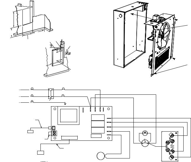
Installation of Back Box in
Existing Construction
1.Provide a wall opening 14-1/2" (362 mm) wide by 18-1/2" (470 mm) high at the desired mounting height, but no closer than 12" (305 mm) from floor or adjacent wall. (See Figure 2.) Locate so at least one side of opening is at wall stud.
2.Run a power supply cable into the knockout area in the upper right hand corner of the wall opening (see Figure 2). All wiring must be in accordance with National and Local Electrical Codes. Refer to Specifications for correct wire size.
3.Remove ON/OFF switch bracket by loosening two screws on the right side.
4.Install a cable clamp in the knockout in the top of the back box.
5.Insert power supply cable through cable clamp, allowing at least 6" (152 mm) of leads to extend inside the back box. Connect the blue lead wires of ON/OFF switch to the supply wire leads using wire connectors (see Figure 3, Wiring Diagram).
NOTE: If power supply is provided by standard non-metallic sheathed cable (Romex) and the supply voltage is 240 or 208 volts (two power wires), the white wire color must be changed using black electrical tape to comply with the NEC. White is only allowed for a Neutral conductor.
6.Connect building ground conductor to the back box using the green screw located in the inside top of the back box.
7.Secure ON/OFF switch bracket in place by tightening screws.
8.Insert back box in wall opening being careful not to damage the supply wiring. Secure the back box in place with wood screws or nails.
Installation of Heater Assembly
Carefully position the heater assembly, with fan on top, and element on bottom into the back box (see Figure 4).
NOTE: The heater assembly must be carefully positioned to ensure the wires and wire connector are not trapped between the heater assembly and the back box.
Once the heater assembly is positioned correctly in the back box, fasten securely using the four screws provided, one in each corner (see Figure 4).
12” Min. |
|
12” Min. |
Cable |
|
|
|
(305 mm) |
|
|
(305 mm) |
14 1/2” Min. |
Ground |
clamp |
Power supply cable |
|
||||
|
(362 mm) |
screw |
|
Lead wires (Blue) |
 ON/OFF switch
bracket with switch
and leads
Back Box
Nail or screw (2 each side)
 Mounting Screw
Locations
 Mounting Screw
Locations
Figure 2 - Locating Back Box in Existing Construction |
|
|
Figure 4 - Installation of Heater Assembly |
|||||
|
ON/OFF SWITCH |
|
|
|
|
|
|
|
L2/N |
L2/N |
|
L2/N |
|
|
|
|
|
|
*BLACK |
*BLUE |
RED |
|
|
|
|
|
L1 |
L1 |
|
L1 |
|
|
|
|
|
|
BLACK |
BLUE |
BLACK |
|
|
|
|
|
G |
G |
|
|
|
|
|
|
|
|
|
GREEN |
G |
|
|
|
|
|
*BLACK AND *BLUE LEAD WIRES ARE |
|
W4 |
W5 |
W6 |
W6 |
|
|
|
IDENTIFIED WITH WHITE TAPE AT EACH |
|
|
|
|
|
|
|
|
STRIPPED END TO INDICATE THAT THE |
|
|
|
|
|
|
|
|
NEUTRAL FOR THE 277V MODELS ARE |
|
VDR1 |
|
|
|
|
|
|
TO BE CONNECTED TO THESE LEADS. |
|
|
|
|
BLACK |
RED |
||
|
Transformer |
|
|
|
||||
|
|
|
|
|
|
E1 |
|
BLACK |
|
THERMISTOR |
|
|
|
|
E2 |
|
|
|
|
|
|
|
|
|
|
|
|
|
|
|
|
|
|
|
BLUE |
|
|
S1 |
|
|
|
E3 |
|
|
|
|
|
|
|
|
|
|
|
|
|
S2 |
|
|
|
FAN-N |
LIGHT |
YELLOW |
|
|
|
CONTROL BOARD |
|
|
|
||
|
|
A |
|
|
|
|
|
|
|
|
|
|
|
FAN-A |
|
|
|
|
|
B |
|
|
|
|
|
|
|
|
|
|
|
|
|
|
|
RED JUMPER WIRE FOR |
|
|
|
|
|
|
|
|
BUILDING MANAGEMENT |
|
|
|
|
|
|
|
|
SYSTEM CONNECTION |
|
|
|
|
|
|
|
|
|
|
|
DATA CABLE |
|
|
|
MANUAL |
RED |
RESET
MOTOR LEAD
MOTOR
MOTOR LEAD
Field Connections
ELEMENT
Figure 3 - Wiring Diagram
3
 Loading...