

Page 1
READ AND SAVE THESE INSTRUCTIONS
RV 16
POWERED A TTIC VENTILA T OR
WARNING
To Reduce The Risk Of Fire Or Electrical Shock, Do Not Use This
With Any Solid-State Speed Control Device.
GENERAL SAFETY GUIDELINES
1. Please read all the instructions carefully before installing this ventilator. Failure to follow instructions
could cause serious bodily injury and/or property damage.
2. WARNING: TO AVOID POSSIBILITY OF ELECTRIC SHOCK OR OTHER SERIOUS INJURY, THE
INSTALLER MUST KEEP ALL ELECTRIC POWER TO FAN DISCONNECTED
DURING INSTALLATION AND WIRING.
3. Electrical connections and all wiring should be in accordance with the National Electrical Code and all
local codes that may apply.
4. THIS VENTILATOR IS INTENDED TO BE INSTALLED SUCH THAT THE UNGUARDED FAN BLADE
FACES AN UNOCCUPIED SPACE ONLY. THE UNGUARDED FAN BLADE ON THIS VENTILATOR
SHOULD NEVER BE EXPOSED TO AN AREA OCCUPIED BY PEOPLE OR ANIMALS.
5. WARNING: TO AVOID POSSIBILITY OF ELECTRIC SHOCK OR OTHER SERIOUS INJURY
TURN OFF ALL ELECTRICAL POWER - REMOVE FUSE OR DISCONNECT CIRCUIT
BREAKER - BEFORE SERVICING UNIT!
6. Sufficient air is needed for proper combustion and exhausting of gases through the flue (chimney) of fuel
burning equipment to prevent back drafting. Follow the heating equipment manufacturer’s guideline and safety
standards such as those published by the National Fire Protection Association (NFPA), and the American
Society for Heating, Refrigeration and Air Conditioning Engineers (ASHRAE), and local code authorities.
A TTENTION
THIS VENTILATOR’S FLASHING PLATE MAY POSSIBLY HAVE BEEN DISTORTED DURING SHIPPING AND
HANDLING. ANY SUCH DISTORTION DOES NOT REPRESENT DEFECTIVE PRODUCT AND IS NOT
RETURNABLE FOR THAT REASON. FLASHING MATERIAL IS PURPOSELY DESIGNED TO BE SOFT AND
FLEXIBLE IN ORDER TO ALLOW THE FLASHING PLATE TO CONFORM TO THE CONTOUR OF THE ROOF.
Page 2
INSTALLATION
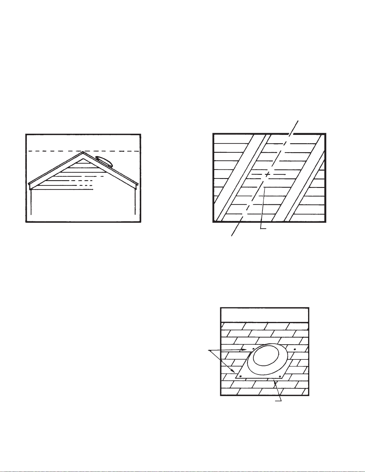
1. The unit should be installed as close to the center of the roof ridgeline as possible on the rear slope of
the roof, with uppermost portion of ventilator dome just below ridge level. See Fig. 1.
2. After locating unit in desired installation position on top of roof, measure from the unit to the ends of
the roof and to the ridgeline. Using these measurements, locate the spot inside the attic directly
under the spot on the roof where the unit has been placed. Locate a centerline position between two
rafters as close as possible to this established position and drill a pilot hole through the roof from the
inside. See Fig. 2.
3. If roof rafters are on 24” centers, cut a 21” diameter hole through the roof, using drilled hole as center. If roof
rafters are on 16” centers, cut a rectangular hole centered around the drilled hole 15” wide (or as wide as rafters
will allow) by 20” long.
4. With mounting plate parallel to ridgeline of roof, slide the upper outer flange of the plate under the row of shingles
just above the cutout so that the housing portion of unit can be centered in the cutout opening. See Fig. 3.
5. Caulking or roofing cement must be used to seal
the mounting plate to the roof, especially bottom
and side areas of flange not covered by shingles.
6. With unit in place, nail the top left corner and top
right corner of flange to roof decking and rafters
with galvanized roof nails. This is accomplished
by nailing directly through the aluminum plate.
Nail the bottom of the flange the same way. Check
to be sure all shingles are securely and neatly in
place over top portion of flange. See Fig. 3.
Caulking nail heads is recommended.
7. Installation should be water checked by using a
garden hose and spraying water directly on top of
unit. Do not spray water directly into vent opening.
Nails
FIG. 3
FIG. 1
FIG. 2
Ridgeline
Apply Caulking
Front
C
L
Drill Hole
Rafter
Rafter
Page 3

AUTOMATIC TEMPERATURE CONTROL
WIRING DIAGRAM
WIRING
8. Wiring of the unit is done inside the attic. The outlet box can be screwed or nailed to a rafter by
mounting bracket provided. If nailed, remove thermostat from box before nailing to avoid damage.
Connections to existing circuit must conform to local electrical code regulation. See Fig. 4.
9. The thermostat has an adjustable range from 60 to 120 degrees. It operates on a 15 degree differential. For example, the factory setting is 100 degrees. At this setting, as soon as the temperature
reaches 115 degrees, the thermostat will close and start the ventilator. When the temperature has
been reduced to 100 degrees, the thermostat will open and the ventilator will stop. The dial pointer
may be set at the temperature that is best for local conditions. REMEMBER THE 15 DEGREE DIFFERENTIAL. If the dial pointer is set on 120 degrees, the ventilator will start at 135 degrees and
operate until the temperature has been reduced to 120 degrees . . . . a difference of 15 degrees.
ATTIC INTAKE AREA
Sufficient intake area must be provided in the attic to assure that the fan will not be overloaded and that it
will deliver its rated CFM. This can be accomplished with some type of attic venting such as gable louvers
or under-eave vents. The table below shows the minimum intake area needed for each fan installed.
MINIMUM ATTIC INTAKE AREA REQUIRED
(All Areas Are In Square Feet)
UNRESTRICTED* WOOD LOUVER* METAL LOUVER*
OPENING REQD. OPENING REQD. OPENING REQD.
RV 16 3 6.75 5.25
PRV16 2.4 5.4 4.2
*The values given are for openings covered with 1/2” hardware cloth or large mesh expanded metal. If no
screen is used, reduce values shown by 20%. If fly screen is used, double the values shown.
DIMENSIONS
TO FAN
MOTOR
THERMOSTAT AND
JUNCTION BOX ASSEMBLY
120V. 60 HZ.
SUPPLY
WHITE
GROUND
BLACK
FIG. 4
FIG. 5
26” DIA.
16
3
⁄4” DIA.
27” SQUARE
3” HIGH VENTURI
61⁄2”
2”
Page 4

MAINTENANCE
The unit is designed to provide years of trouble-free service.
The Motor is known as a “Lifetime Lubricated Motor” which
theoretically means it should never need oiling. However, it
is good maintenance procedure to lubricate the motor with
2-3 drops of light oil at least once a year. In some cases, it
is necessary to remove the motor for servicing. Therefore,
for removal:
FROM ROOF: Remove dome, loosen set screw in
blade, loosen motor mount band and slide motor out form
the bottom (Note original position of these components to
simplify reassembly and maintain efficiency).
FROM A TTIC: Loosen set screw in blade, loosen
motor mount band and slide motor out.
CAUTION: MOTORS ARE THERMOSTAT CONTROLLED
and may start without warning! Therefore, disconnect power
source before attempting to service unit. If disconnect is out
of sight, lock it in open position and tag to prevent application of power.
Tools required to service unit:
(1) 5/16” Box End Wrench or Nut Driver, (1) 1/8” Hex Key
Wrench, and (1) Phillips Type Screw Driver.
Part No. 5200-2554-000 PPD 035
3-00
REF.
NO. DESCRIPTION QTY.
1 Dome Cover 1
2 * Screw, 10-12 x 3/8 Type AB Hex Head 4
3 * Nut, Serrated Flanged 1/4-20 4
4 Bracket, Dome 4
5 Screen 1
6 Fan Blade Assembly 1
7† Set Screw, 1/4-36 x 5/16 1
8 Venturi Plate 1
9 Nut, Speed 1/4-20 1
10* Screw, 1/4-20 x 1 1/2 2
11 Motor Mount Assembly 1
12 Grommet 4
13* Screw, 1/4-20 x 1 4
14 Motor, PSC 120V 1/5 HP 1
15 Boot, Capacitor Terminal Cover 1
16 Capacitor, 4 MFD 370 VAC 1
17 Connector, BX 1
18 Flexible Conduit 1
19 Thermostat & Junction Box 1
20† Instruction Sheet 1
* Standard Hardware Item, Available Locally
† Item Not Shown
OIL
HOLES
1
2
3
4
5
6
8
9
10
11
12
13
14
15
16
17
18
19
2
HOW TO ORDER REPAIR PARTS
In order to obtain any needed repair or replacement
parts, warranty service or technical information, please
contact Marley Engineered Products Service Center tollfree by calling 1-800-642-HEAT.
When ordering repair parts, always give the information listed as follows:
1. The Part Number
2. The Model Number
3. The Part Description
4. Date of Manufacture
470 Beauty Spot Rd. East
Bennettsville, SC 29512 USA
 Loading...