

Page 1
COVE HEATER
Patent Pending
Model D
Installation & Maintenance Instructions
WARNING
!
Read Carefully
prevent difficulties that might arise during installation of
heaters. Studying the instructions first may save you considerable time and money later. Observe the following procedures, and cut your mounting time to a minimum. TO
REDUCE RISK OF FIRE OR ELECTRIC SHOCK:
1. Disconnect all power coming to heater at main service panel
before wiring or servicing.
2. All wiring must be in accordance with the National and Local
Electrical Codes and the heater must be grounded.
3. Verify the power supply voltage coming to heater matches the
ratings printed on the heater nameplate before energizing.
4. This heater is hot when in use. To avoid burns, do not let bare
skin touch hot surfaces.
- These instructions are written to help you
FILE #E21609
5. Do not insert or allow foreign objects to enter any ventilation or
exhaust opening as this may cause an electric shock, fire,or
damage to the heater.
6. Do not block air intakes or exhaust in any manner. Keep combustible materials, such as crates, drapes, etc., away from
heater. Do not install behind door, furniture, towels, or boxes.
7. A heater has hot and arcing or sparking parts inside. Do not use
it in areas where gasoline, paint, or flammable liquids are used
or stored.
8. Use this heater only as described in this manual. Any other use
not recommended by the manufacturer may cause fire, electric
shock, or injury to persons.
9. This heater is not approved for use in corrosive atmospheres
such as marine, green house, or chemical storage areas.
CAUTION
1. THE HEATER MUST BE MOUNTED AT LEAST 6' (182.8 cm) or
(1.83 m ) ABOVE THE FLOOR TO PREVENT ACCIDENTAL CONTACT.
2. TO PREVENT POSSIBLE OVERHEATING OR DAMAGE DUE TO
OVERHEATING, REFER TO FIGURES 1 AND 4 FOR SIDE, TOP,
AND BOTTOM CLEARANCE REQUIREMENTS.
!
GENERAL
When installing 2 or more heaters along one wall:
1. Mount heaters allowing adequate spacing between heaters as
shown in Table 1.
2. Install optional RCCSPC Splice Plate (if desired) per instructions
provided with RCCSPC.
When mounting heaters end to end add the “maximum allowable
expansion” of each heater and provide that clearance from end to end
of units. See Table 1.
Table 1
MAXIMUM ALLOWABLE MOUNTING SLOT
WATTS
450
600
750
900
1050
1200
1500
1800
EXPANSION DISTANCE (CTR-CTR)
1/8” (4mm)
1/4” (7mm)
1/2” (13mm)
3/4” (19mm)
7/8” (23mm)
1-1/8 (29mm)
1-3/8 (35mm)
1-1/2” (38mm)
27.75” (705mm)
40.75” (1,035mm)
52.75” (1,340mm)
64.75” (1,645mm)
76.75” (1,949mm)
87.75” (2,229mm)
111.75” (2,838mm)
125.75” (3,194mm)
SAVE THESE INSTRUCTIONS
MOUNTING THE HEATER
For 450 to 1200 Watt Heaters:
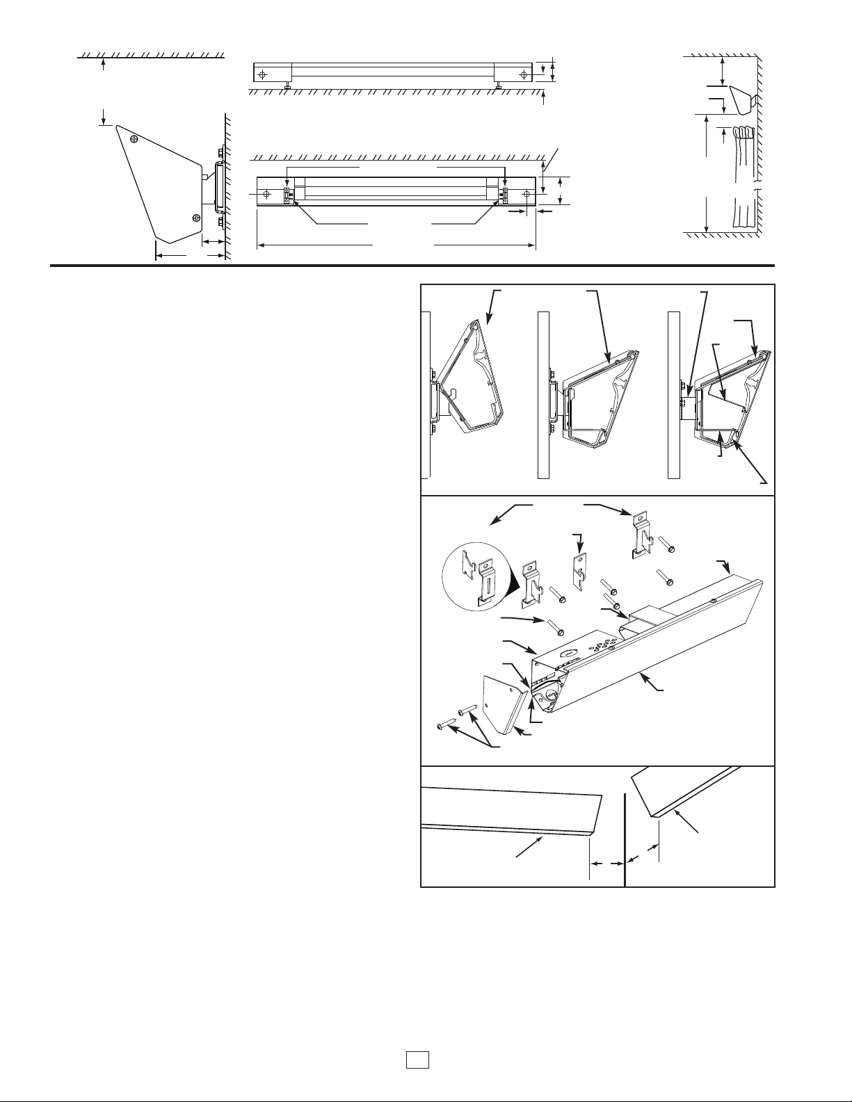
1. Select correct mounting distance from the ceiling material per
Figure 1. Using Table 1, determine the center to center distance
of the end wall brackets for the particular model (wattage) to be
mounted. Divide this value by 2 to determine the approximate
location to mount the center wall bracket. Mark these locations on
the chosen wall. Locate a stud nearest the center wall bracket
mark. Use this stud for the bracket location. (Disregard original
mark mentioned above) Assemble end wall brackets as shown in
Figure 3.
2. Using the template (provided), align the top of the template with
the ceiling and the center of the pre-punched holes with the
bracket marks on the wall. Choosing the proper ( end or middle)
bracket location holes, mark the bracket pilot hole locations using
the selected pre-punched holes provided on the template. With
the fasteners provided, mount the assembled end wall brackets
and center wall bracket to the wall. Using a tape measure, determine the distance between the center (slot) of the left end wall
bracket and the hook of the center wall bracket. Add 3-5/8 inches
(92 mm) to this value and record it for center support bracket
location on the cove heater.
3. Orient the cove heater face down on a protective flat surface.
Using the value recorded in step 2, measure this distance from
the left end of the cove heater and mark this location on the back
surface of the panel. Slide the center support bracket to the
marked position on the panel, aligning the center of the bracket
with this mark.
Page 2
4
” (102 mm) MIN. (DRY WALL CEILINGS)
6
” (152 mm) MIN. (LAY IN OR VINYL
CEILINGS OR PLASTIC MOLDING)
1
“ (25.4 mm) MIN. BETWEEN BOTTOM
OF HEATER AND ANY FABRIC
6‘ MINIMUM
(1.83 m)
CLEARANCE
TO FLOOR
CURTAINS
CEILING
WALL
FLOOR
MOUNTING RESTRICTIONS
}
4” (102 mm)(DRY WALL CEILINGS)
6” (152 mm) LAY IN OR VINYL CEILINGS
OR PLASTIC MOLDING)
BACK VIEW
MOUNTING SLOTS
MOUNTING BRACKETS
34” TO 132”
(0.86 M to 3.35 M)
CEILING
WALL
3”
2”
TOP VIEW
4-3/16“ (106.4 mm)
1-1/2” (38.1 mm)
HEATERS TO BE MOUNTED
AT LEAST SIX (6) FEET
(1.83 M) FROM THE FLOOR.
MINIMUM CLEARANCES:
• 4” (102 mm) MIN. TO DRY WALL CEILING.
• 6” (152 mm) MIN. TO LAY-IN OR VINYL CEILING
OR PLASTIC MOLDING.
CEILING
2-1/2”
13/16”
Figure 1
HEATE R
HEATE R
4”
4”
MOUNTING THE HEATER (Continued)
4. To mount cove heater, attach center support bracket to the center
wall bracket by tilting the heater back and allowing the upper slot
to fall onto the bracket hook per Figure 2. Attach the junction
boxes to the end wall brackets in a similar manor. Bring the cove
For 1500 to 1800 Watt Heaters:
The 1500 & 1800 watt cove heaters require the additional support of
(2) center wall brackets due to the extra length. The mounting steps
are similar to the 450 to 1200 watt cove heater with the following
exceptions:
1. After the approximate center location between the end wall brack-
ets has been determined, measure 30 inches (762 mm) on each
side of this location to determine the approximate location to
mount the center wall brackets. Locate a stud nearest each mark.
Use these studs for the center wall bracket locations. (Disregard
original 30 inch location marks)
2. Using the provided template, align the top of the template with the
ceiling and the center of the pre-punched holes with the bracket
marks on the wall. Choosing the proper bracket location holes,
mark the bracket pilot hole locations using the selected prepunched holes provided on the template. With the fasteners provided, mount the assembled end wall brackets and center wall
brackets to the wall. Measure the distance between the center
(slot) of the left end wall bracket and the hook of the left center
wall bracket. Add 3-5/8 inches (92 mm) to this (left end) value and
record it for the left center support bracket location on the cove
heater. Determine the distance between the center of the right
end wall bracket and the hook of the right center wall bracket.
Add 3-5/8 inches (92 mm) to this (right end) value and record it
for the right center support bracket placement on the cove heater.
3. Orient the cove heater face down on a protective flat surface.
Using the left end value recorded in step 2, measure this distance
from the left end of the cove heater and mark this location on the
back surface of the panel. Using the right end value recorded in
step 2, measure this distance from the right end of the cove
heater and mark this location on the back surface of the panel.
Slide the center support brackets to the marked positions on the
panel, aligning the center of the brackets with each mark.
4. To mount cove heater, attach center support brackets to the cen-
ter wall brackets by tilting the heater back and allowing the upper
slot to fall onto the bracket hook per Figure 2. Attach the junction
boxes to the end wall brackets in a similar manor. Bring the cove
heater forward to lock into place.
5. The cove heater can be wired from either end of the heater.
Install a cable clamp (supplied by others) in one of the knockouts
located in back of the junction boxes you plan to use. Insert the
power supply cable through the cable clamp allowing approximately 6” (152mm) of cable length to remain inside the box to
facilitate wiring. Add at least 2 inches of cable loop between wall
and knockout entering the junction box to allow for heater expansion.
heater forward to lock into place.
ALIGN JUNCTION
BOX SLOT WITH
BRACKET HOOK
Figure 2
#10-16 X 1-1/2”
LONG SCREWS
JUNCTIONBOX
ELEMENT LEAD
Figure 3
MOUNTING HEATER
TO END BRACKET
ASSEMBLY
HEATER LOCKED IN
POSITION ON END
WALL BRACKET
END WALL
BRACKET ASSEMBLY
CENTER WALL
BRACKET
CENTER
SUPPORT
BRACKET
CROSSOVER LEAD
END CAP
#8-18 X 1” LONG SCREWS
CUTAWAY SHOWING
CENTER MOUNTING
BRACKET DETAILS
CENTER
SUPPORT
BRACKET
BACK WRAP
HEAT SHIELD
COVE HEATER
FRONT PANEL
OP
T
LANGE
F
BACK
WRAP
WIREWAY
Figure 4
6. Refer to wiring diagrams on next page.
7. Attach end caps (found in parts bag) as shown in Figure 3.
1. Heaters must be located so that the ends of each heater are
4 inches (102 mm) from side wall. See Figure 4.
2
INSTALLATION AT CORNER
Page 3
{
{
GREEN
GROUND
WIRE
POWER
SUPPLY
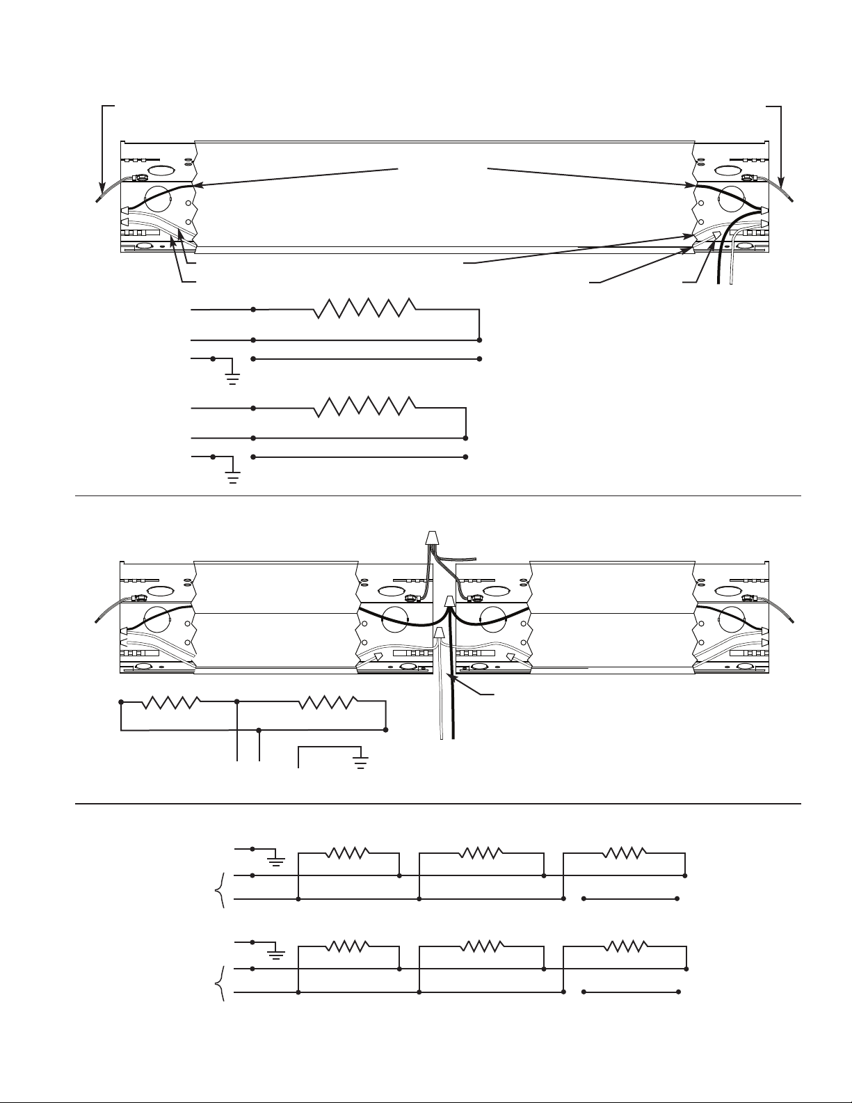
SINGLE UNIT WIRING – SUPPLY IN MIDDLE
IGHT HAND FIELD CONNECTION SHOWN. TO WIRE ON LEFT HAND SIDE:
R
1) SEPARATE ELEMENT LEAD FROM CROSS-OVER WIRE ON LEFT SIDE.
(
2) USING WIRE NUT, CONNECT LEAD WIRE TO CROSS-OVER WIRE ON RIGHT SIDE.
(
3) CONNECT L1 TO ELEMENT LEAD AND L2 (OR NEUTRAL) TO CROSSOVER WIRE
(
N LEFT SIDE.
O
LEMENT LEAD
E
20V - YELLOW
1
08V - BLUE
2
40V - RED
2
77V - BROWN
2
CROSS-OVER WIRE (BLACK 208/240V, WHITE 120/277V)
RED CROSS-OVER WIRE USED FOR MULTIPLE END CONNECTED HEATERS ONLY.
L1
L2
BLACK
RED
208 OR 240 VOLT MODELS
ELEMENT
WARNING:
CHECK HEATER NAMEPLATE AT
INSTALLATION TO VERIFY UNIT VOLTAGE RATING IS THE SAME AS THE SUPPLY VOLTAGE.
FACTORY
SUPPLIED
WIRE NUTS
(5 REQUIRED)
GREEN
GROUND
WIRE
SUPPLY
WIRING
POWER
SUPPLY
BLACK*
* Use white cross-over
wire on the heaters
rated 120V or 277V
L
LEMENT
N
WHITE
ED
R
120 OR 277 VOLT MODELS
E
ALL UNITS MAY BE WIRED FROM EITHER END.
HEATER GROUNDING WIRE FOR SUPPLY
GROUND CONNECTION FOUND ON EITHER END.
TWO UNIT WIRING – SUPPLY IN MIDDLE
TO GROUND
SEE TABLE 1 FOR EXPANSION DIMENSIONS
SUPPLY
BLACK*
SUPPLY
GROUND
CAUTION:
TOTAL LOAD MUST NOT EXCEED
16AMPS FOR INTERCONNECTED HEATERS.
(A)
SUPPLY
(B)
SUPPLY
Figure 5. Heater Wiring
GROUND
GROUND
TWO OR MORE HEATERS – SUPPLY AT END
L1
L2
N
L1
(A) 240 / 208 VOLT HEATERS (B) 120 VOLT OR 277 VOLT HEATERS
FOR GROUND CONTINUITY BETWEEN ADJACENT HEATERS USE GROUND WIRE PROVIDED.
SEE NOTES ABOVE FOR TWO UNIT WIRING – SUPPLY IN MIDDLE.
Black
Red
White
Red Red Red
Black
Red
White
Black
Red
White
Page 4
IMPORTANT INFORMATION
REPLACEMENT PARTS
Elements and aluminum extrusions are not replaceable. Due to the
intrinsic design of the cove heater, we are unable to furnish elements,
extrusions, wires, back shields, and junction boxes as replaceable parts,
however, the following parts kits are available.
Part Kit 1. Part number 3303-2032-000 for white cove heaters.
Part Kit 2. Part number 3303-2032-001 for Dove Grey cove heaters.
Part Kit 3. Part number 3303-2032-002 for Desert Tan cove heaters.
The above kit contains end caps, end brackets, center bracket, mounting template, and mounting hardware.
ACCESSORIES (Optional)
RCCT
RCCSPC
Integral Thermostat: Range 45-90ºF with positive off.
Splice Plate Assembly.
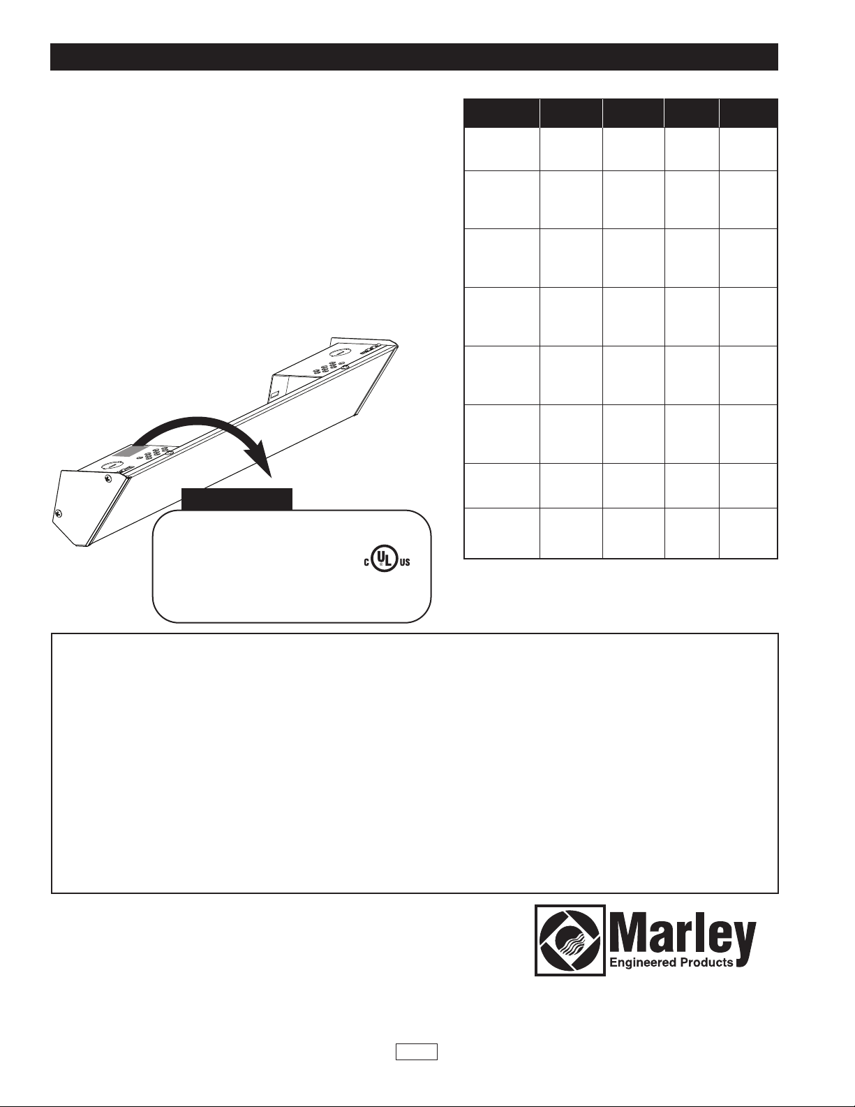
NAMEPLATE
E
DATE CODE
0904
774G LISTED
ROOM HEATER
MODEL NO.
COVE HEATER (PATENT PENDING)
APPAREIL DE CHAUFFAGE
ENCASTRÉ
RADIATOR EQUINERO DE TECHO
VOLTS:
WATTS: 450 AMPS 3.75
MARLEY ENGINEERED PRODUCTS
BENNETTSVILLE, SC 29512 USA
C4 512D
120 A.C. 60HZ
X
E
A
M
P
L
Specifications
Model No. Watts Voltage Amps (inches)
C4508D
C4512D
C4524D
C6008D
C6012D
C6024D
C6027D
C7508D
C7512D
C7524D
C7527D
C9008D
C9012D
C9024D
C9027D
C10508D
C10512D
C10524D
C10527D
C12008D
C12012D
C12024D
C12027D
C15008D
C15024D
C15027D
C18008D
C18024D
C18027D
450W 120V 3.7 34
600W 120V 5.0 47
750W 120V 6.2 59
900W 120V 7.5 71
1050W 120V 8.8 83
1200W 120V 10.0 94
1500W 240V 6.2 118
1800W 240V 7.5 132
208V 2.2 34
240V 1.9 34
208V 2.9 47
240V 2.5 47
277V 2.2 47
208V 3.6 59
240V 3.1 59
277V 2.7 59
208V 4.3 71
240V 3.7 71
277V 3.2 71
208V 5.0 83
240V 4.4 83
277V 3.8 83
208V 5.8 94
240V 5.0 94
277V 4.3 94
208V 7.2 118
277V 5.4 118
208V 8.7 132
277V 6.5 132
Length
All products manufactured by Marley Engineered Products are warranted against defects in workmanship and materials for one year from date of installation, except
LIMITED WARRANTY
heating elements which are warranted against defects in workmanship and materials for five years from date of installation. This warranty does not apply to damage
from accident, misuse, or alteration; nor where the connected voltage is more than 5% above the nameplate voltage; nor to equipment improperly installed or wired or
maintained in violation of the product’s installation instructions. All claims for warranty work must be accompanied by proof of the date of installation.
The customer shall be responsible for all costs incurred in the removal or reinstallation of products, including labor costs, and shipping costs incurred to return products to Marley Engineered Products Service Center.Within the limitations of this warranty, inoperative units should be returned to the nearest Marley authorized service center or the Marley Engineered Products Service Center, and we will repair or replace, at our option, at no charge to you with return freight paid by Marley. It is
agreed that such repair or replacement is the exclusive remedy available from Marley Engineered Products.
THE ABOVE WARRANTIES ARE IN LIEU OF ALL OTHER WARRANTIES EXPRESSED OR IMPLIED, AND ALL IMPLIED WARRANTIES OF MERCHANTABILITY
AND FITNESS FOR A PARTICULAR PURPOSE WHICH EXCEED THE AFORESAID EXPRESSED WARRANTIES ARE HEREBY DISCLAIMED AND EXCLUDED
FROM THIS AGREEMENT. MARLEY ENGINEERED PRODUCTS SHALL NOT BE LIABLE FOR CONSEQUENTIAL DAMAGES ARISING WITH RESPECT TO THE
PRODUCT, WHETHER BASED UPON NEGLIGENCE, TORT, STRICT LIABILITY, OR CONTRACT.
Some states do not allow the exclusion or limitation of incidental or consequential damages, so the above exclusion or limitation may not apply to you. This warranty
gives you specific legal rights, and you may also have other rights which vary from state to state.
For the address of your nearest authorized service center, contact Marley Engineered Products in Bennettsville, SC, at 1-800-642-4328. Merchandise returned to the
factory must be accompanied by a return authorization and service identification tag, both available from Marley Engineered Products. When requesting return authorization, include all catalog numbers shown on the products.
HOW TO OBTAIN WARRANTY SERVICE AND
WARRANTY PARTS PLUS GENERAL INFORMATION
1. Warranty Service or Parts
2. Purchase Replacement Parts
3. General Product Information
Note:
When obtaining service always have the following:
1. Model number of the product
2. Date of manufacture
3. Part number or description
1-800-642-4328
1-800-654-3545
www.marleymep.com
Part No. 5200-2668-005
ECR 39014
02/11
4
470 Beauty Spot Rd. East
Bennettsville, SC 29512 USA
Page 5

CALEFACTOR
ESQUINERO DE TECHO
Patente en trámite
Modelo D
Instrucciones de instalación y mantenimiento
!
Lea cuidadosamente
superar las dificultades que podrían aparecer durante la instalación de calefactores. El estudio previo de estas instrucciones puede ahorrarle considerable tiempo y dinero en el futuro. Observe los procedimientos que
siguen, y reducirá el tiempo de montaje a un mínimo.
PARA REDUCIR EL RIESGO DE INCENDIO O CHOQUE ELÉCTRICO:
1. Antes de proceder a tareas de conexionado o de reparación del calefactor, desconecte toda la alimentación eléctrica que llega al mismo desde
el tablero principal de servicio.
2. Todo el conexionado debe hacerse de conformidad con los Códigos
Eléctricos nacionales y locales, y el calefactor debe estar conectado a
tierra.
3. Antes de aplicar alimentación eléctrica, verifique que la tensión de alimentación provista al calefactor sea compatible con la tensión nominal
impresa en la placa de características del mismo.
4. Cuando está en funcionamiento, el calefactor está muy caliente. Para
evitar quemaduras, no deje que su piel haga contacto directo con las
superficies calientes.
1. EL CALEFACTOR DEBE MONTARSE AL MENOS A 1,83 m (6’) POR ENCIMA
DEL PISO, PARA IMPEDIR CONTACTOS ACCIDENTALES.
2. PARA PREVENIR UN POSIBLE SOBRECALENTAMIENTO O DAÑOS DEBIDOS
AL MISMO, OBSERVE LOS REQUISITOS DE ESPACIO LIBRE LATERAL,
SUPERIOR E INFERIOR INDICADOS EN LAS FIGURAS 1 Y 4.
Al instalar dos o más calefactores a lo largo de una pared:
1. Monte los calefactores dejando un espacio adecuado entre ellos,
tal como lo indica la Tabla 1.
2. Si lo desea, puede instalar la Placa de Unión opcional RCCSPC
siguiendo las instrucciones que se proveen con ella.
Al montar calefactores adyacentes (extremo a extremo), agregue la
‘máxima expansión admisible’ de cada calefactor, y prevea ese espacio libre entre los extremos de las unidades. Vea la Tabla 1.
Tabla 1
POTENCIA
(WATTS)
450
600
750
900
1050
1200
1500
1800
– Estas instrucciones están escritas para ayudarle a
ATENCIÓN
GENERALIDADES
MÁXIMA EXPANSIÓN DISTANCIA ENTRE RANURAS
ADMISIBLE DE MONTAJE (ENTRE CENTROS)
1/8” (4mm)
1/4” (7mm)
1/2” (13mm)
3/4” (19mm)
7/8” (23mm)
1-1/8 (29mm)
1-3/8 (35mm)
1-1/2” (38mm)
!
ADVERTENCIA
27.75” (705mm)
40.75” (1,035mm)
52.75” (1,340mm)
64.75” (1,645mm)
76.75” (1,949mm)
87.75” (2,229mm)
111.75” (2,838mm)
125.75” (3,194mm)
REGISTRO Nº E21609
5. No inserte ni permita que entren objetos extraños en ninguna abertura
de ventilación o de descarga, porque esto puede ser causa de choque
eléctrico, incendio o daño al calefactor.
6. No bloquee de ningún modo las entradas o la descarga de aire.
Conserve los materiales combustibles como cajones, cortinados, etc.,
alejados del calefactor. No lo instale detrás de puertas, muebles,
toalleros o cajas.
7. Un calefactor tiene en su interior piezas calientes, y piezas en donde se
producen arcos o chispas. No lo utilice en áreas en las que se utilice o
almacene gasolina, pintura o líquidos inflamables.
8. Utilice este calefactor únicamente en la forma prevista en este manual.
Cualquier otra forma de uso no recomendada por el fabricante puede ser
causa de incendio, choque eléctrico o daños personales.
9. Este calefactor no está aprobado para su uso en atmósferas corrosivas
tales como áreas marítimas, invernaderos o lugares de almacenamiento
de productos químicos.
MONTAJE DEL CALEFACTOR
Para calefactores de 450 a 1200 watts:
1. Seleccione la distancia correcta de montaje para el material del
cielorraso, de acuerdo con la Figura 1. Mediante la Tabla 1, determine la distancia entre centros de los soportes extremos de pared
según la potencia en watts del modelo particular que se va a montar. Divida este valor por 2 para determinar la ubicación aproximada
de montaje del soporte central de pared. Marque estas ubicaciones
en la pared elegida. Localice un travesaño cercano a la marca para
el soporte central de pared. Use este travesaño para la ubicación
del soporte (no tenga en cuenta la marca original mencionada
antes). Arme los soportes extremos de pared como se indica en la
Figura 3.
2. Usando la plantilla provista, alinee el extremo superior de la misma
con el cielorraso, y el centro de los agujeros preperforados con las
marcas de los soportes sobre la pared. Eligiendo los agujeros adecuados de ubicación de los soportes (extremos y central), marque
las ubicaciones de los agujeros de guía para los soportes usando
los agujeros preperforados de la plantilla seleccionados. Con los
sujetadores provistos, monte en la pared los soportes extremos
armados y el soporte central. Mediante una cinta métrica, determine
la distancia entre el centro (ranura) del soporte extremo de pared
del lado izquierdo y el gancho del soporte central de pared.
Agregue 92 mm (3-5/8 pulgadas) a este valor, y registre el resultado para la ubicación de la escuadra de soporte central en el calefactor.
3. Oriente el calefactor con el frente hacia abajo, sobre una superficie
plana protectora. Usando el valor registrado en el paso 2, mida esta
distancia desde el extremo izquierdo del calefactor y marque esta
ubicación en la superficie del dorso del panel. Deslice la escuadra
de soporte central hasta la posición marcada en el panel, alineando
el centro del soporte con esta marca.
GUARDE ESTAS INSTRUCCIONES
Page 6

4
” (102 mm) MIN. (DRY WALL CEILINGS)
6
” (152 mm) MIN. (LAY IN OR VINYL
CEILINGS OR PLASTIC MOLDING)
1
“ (25.4 mm) MIN. BETWEEN BOTTOM
OF HEATER AND ANY FABRIC
6‘ MINIMUM
(1.83 m)
CLEARANCE
TO FLOOR
CURTAINS
CEILING
WALL
FLOOR
MOUNTING RESTRICTIONS
}
4” (102 mm)(DRY WALL CEILINGS)
6” (152 mm) LAY IN OR VINYL CEILINGS
OR PLASTIC MOLDING)
BACK VIEW
MOUNTING SLOTS
MOUNTING BRACKETS
34” TO 132”
(0.86 M to 3.35 M)
CEILING
WALL
3”
2”
TOP VIEW
4-3/16“ (106.4 mm)
1-1/2” (38.1 mm)
HEATERS TO BE MOUNTED
AT LEAST SIX (6) FEET
(1.83 M) FROM THE FLOOR.
MINIMUM CLEARANCES:
• 4” (102 mm) MIN. TO DRY WALL CEILING.
• 6” (152 mm) MIN. TO LAY-IN OR VINYL CEILING
OR PLASTIC MOLDING.
CEILING
2-1/2”
13/16”
HEATE R
HEATE R
4”
4”
IELORRASO
C
ESPACIOS LIBRES MÍNIMOS:
102 mm (4”) MÍNIMO A CIELORRASOS DE PANEL DE YESO.
•
• 152 mm (6”) MÍNIMO A CIELORRASOS SUSPENDIDOS O DE
VINILO, O MOLDURAS PLÁSTICAS.
VISTA SUPERIOR
ARED
P
102 mm (4”) MÍNIMO (CIELORRASOS DE PANEL DE YESO)
152 mm (6”) MÍNIMO (CIELORRASOS SUSPENDIDOS O DE
VINILO, O MOLDURAS PLÁSTICAS)
5,4 mm (1”) MÍNIMO ENTRE LA BASE DEL
2
CALEFACTOR Y CUALQUIER TELA
IELORRASO
C
Figura 1
LOS CALEFACTORES SE
MONTARÁN A 1,83 m (6 PIES)
DEL PISO, COMO MÍNIMO.
MONTAJE DEL CALEFACTOR (continuación)
. Para montar el calefactor, fije la escuadra de soporte central al soporte central de
4
pared inclinando el calefactor hacia atrás y haciendo que la ranura superior caiga
sobre el gancho del soporte, según se indica en la Figura 2. Fije las cajas de
onexiones a los soportes extremos de pared en forma similar. Lleve el calefactor
c
hacia adelante, para fijarlo en su posición.
Para calefactores de 1500 a 1800 watts:
Los calefactores esquineros de techo de 1500 y 1800 watts necesitan dos (2) soportes
centrales de pared adicionales, debido a su mayor longitud. Los pasos de montaje son
similares a los de los calefactores de 450 a 1200 watts, con las excepciones siguientes:
1. Después de haber determinado la ubicación aproximada del centro entre los
soportes extremos de pared, mida 762 mm (30 pulgadas) a cada lado de esta ubi-
cación, para determinar el lugar aproximado de montaje de los soportes centrales
de pared. Localice un travesaño cercano a cada marca. Use estos travesaños
para la ubicación de los soportes centrales de pared (no tenga en cuenta las mar-
cas originales de ubicación a 762 mm / 30 pulgadas).
2. Usando la plantilla provista, alinee el extremo superior de la misma con el cielorra-
so, y el centro de los agujeros preperforados con las marcas de los soportes
sobre la pared. Eligiendo los agujeros adecuados de ubicación de los soportes,
marque las ubicaciones de los agujeros de guía para los soportes usando los agu-
jeros preperforados de la plantilla seleccionados. Con los sujetadores provistos,
monte en la pared los soportes extremos armados y los soportes centrales. Mida
la distancia entre el centro (ranura) del soporte extremo de pared del lado izquier-
do y el gancho del soporte central de pared del lado izquierdo. Agregue 92 mm
(3-5/8 pulgadas) a este valor (extremo izquierdo), y registre el resultado para la
ubicación de la escuadra de soporte central izquierda en el calefactor. Determine
la distancia entre el centro del soporte extremo de pared del lado derecho y el
gancho del soporte central de pared del lado derecho. Agregue 92 mm (3-5/8 pul-
gadas) a este valor (extremo derecho), y registre el resultado para la ubicación de
la escuadra de soporte central derecha en el calefactor.
3. Oriente el calefactor con el frente hacia abajo, sobre una superficie plana protec-
tora. Usando el valor del extremo izquierdo registrado en el paso 2, mida esta dis-
tancia desde el extremo izquierdo del calefactor y marque esta ubicación en la
superficie del dorso del panel. Usando el valor del extremo derecho registrado en
el paso 2, mida esta distancia desde el extremo derecho del calefactor y marque
esta ubicación en la superficie del dorso del panel. Deslice las escuadras de
soporte central hasta las posiciones marcadas en el panel, alineando el centro de
los soportes con cada marca.
4. Para montar el calefactor, fije las escuadras de soporte central a los soportes cen-
trales de pared inclinando el calefactor hacia atrás y haciendo que la ranura supe-
rior caiga sobre el gancho del soporte, según se indica en la Figura 2. Fije las
cajas de conexiones a los soportes extremos de pared en forma similar. Lleve el
calefactor hacia adelante, para fijarlo en su posición.
5. El calefactor esquinero puede conectarse desde cualquiera de sus extremos.
Instale una abrazadera para cables (suministrada por terceros) en alguno de los
prepunzonados ubicados en la parte posterior de las cajas de conexiones que va
a utilizar. Inserte el cable de alimentación eléctrica a través de la abrazadera,
dejando aproximadamente 152 mm (6”) de longitud de cable dentro de la caja,
para facilitar el cableado. Agregue al menos 51 mm (2 pulgadas) de lazo de cable
entre la pared y el prepunzonado de ingreso a la caja de conexiones, para tener
en cuenta la dilatación del calefactor.
VISTA POSTERIOR
CIELORRASO
SOPORTES DE MONTAJE
RANURAS DE MONTAJE
102 mm (4”) MÍNIMO (CIELORRASOS DE PANEL DE
YESO)
152 mm (6”) MÍNIMO (CIELORRASOS SUSPENDIDOS
O DE VINILO, O MOLDURAS PLÁSTICAS)
SPACIO LIBRE
E
ESPECTO AL
R
PISO: 1,83 m
(6 PIES) MÍNIMO
P
ISO
PARED
CORTINAS
RESTRICTIONS DE MONTAGE
ALINEE LA RANURA DE LA
CAJA DE CONEXIONES CON
EL GANCHO DEL SOPORTE
Figura 2
TORNILLOS #10-16 x 1-
1/2” DE LONGITUD
CAJA DE
CONEXIONES
CABLE DE CONEXIÓN DEL
ELEMENTO CALEFACTOR
Figura 3
CALEFACTOR
MONTAJE DEL CALEFACTOR AL
CONJUNTO DEL SOPORTE
EXTREMO
CALEFACTOR TRABADO EN SU
POSICIÓN SOBRE EL SOPORTE
CONJUNTO DE
SOPORTE EXTREMO
DE PARED
SOPORTE CENTRAL
DE PARED
ESCUADRA DE
SOPORTE CENTRAL
CABLE DE INTERCONEXIÓN
TAPA EXTREMA
TORNILLOS #8-18 x 1” DE LONGITUD
CORTE QUE MUESTRA DETALLES
DEL SOPORTE CENTRAL DE
MONTAJE
EXTREMO DE PARED
ESCUADRA
DE SOPORTE
CENTRAL
CANAL DE CABLES
PANTALLA TÉRMICA DE
ENVOLTURA POSTERIOR
PANEL FRONTAL DEL
CALEFACTOR
CALEFACTOR
REBORDE
SUPERIOR
ENVOLTURA
POSTERIOR
Figura 4
6. Vea los diagramas de cableado en la próxima página.
7. Coloque las tapas extremas (que se proveen en la bolsa de piezas) como lo
muestra la Figura 3.
1. Los calefactores deben ubicarse de modo que los extremos de cada
uno se encuentren a 102 mm (4”) de la pared lateral. Vea la Figura 4.
2
INSTALACIÓN EN UNA ESQUINA
Page 7

{
{
CABLEADO DE UNA UNIDAD – ALIMENTACIÓN ELÉCTRICA EN EL MEDIO
SE MUESTRA EL CONEXIONADO EN EL SITIO, EN EL LADO DERECHO. PARA CONECTAR EN EL LADO IZQUIERDO:
(1) SEPARE EL CABLE DE CONEXIÓN DEL ELEMENTO CALEFACTOR DEL CABLE DE INTERCONEXIÓN EN EL LADO IZQUIERDO.
(2) MEDIANTE UNA TUERCA DE EMPALME DE CABLES, CONECTE EL CABLE DE CONEXIÓN AL CABLE DE INTERCONEXIÓN EN EL LADO DERECHO.
ABLE VERDE
C
DE CONEXIÓN
TIERRA
ALIMENTACIÓN
LÉCTRICA
E
(3) CONECTE L1 AL CABLE DE CONEXIÓN DEL ELEMENTO CALEFACTOR Y L2 (O NEUTRO) AL CABLE DE INTERCONEXIÓN EN EL LADO IZQUIERDO.
CABLE DE CONEXIÓN
DEL ELEMENTO
ALEFACTOR
C
120 V - AMARILLO
208 V - AZUL
40 V - ROJO
2
277 V - MARRÓN
CABLE DE INTERCONEXIÓN (NEGRO 208/240 V, BLANCO 120/277 V
CABLE DE INTERCONEXIÓN ROJO, UTILIZADO ÚNICAMENTE PARA CALEFACTORES MÚLTIPLES CONECTADOS
POR EL EXTREMO.
1
L
L2
NEGRO
ROJO
MODELOS DE 208 Ó 240 VOLTS
ELEMENTO CALEFACTOR
ADVERTENCIA:
CARACTERÍSTICAS PARA VERIFICAR QUE LA TENSIÓN NOMINAL DE LA
NIDAD SEA IGUAL A LA TENSIÓN DE LA ALIMENTACIÓN ELÉCTRICA.
U
AL INSTALAR EL CALEFACTOR, REVISE SU PLACA DE
UERCAS DE
T
MPALME DE CABLES
E
UMINISTRADAS POR
S
A FÁBRICA
L
CANTIDAD
(
ECESARIA: 5)
N
CABLE VERDE
DE CONEXIÓN
TIERRA
A
ABLEADO DE
C
ALIMENTACIÓN
LÉCTRICA
E
ALIMENTACIÓN
ELÉCTRICA
CABLEADO DE DOS UNIDADES – ALIMENTACIÓN ELÉCTRICA EN EL MEDIO
NEGRO*
*Utilice el cable blanco de
interconexión en los
calefactores para 120 V
y 277 V
L
N
NEGRO*
ALIMENTACIÓ
N ELÉCTRICA
BLANCO
ROJO
MODELOS DE 120 Ó 277 VOLTS
ELEMENTO CALEFACTO
TIERRA
ALIMENTACIÓN
ELÉCTRICA
TODAS LAS UNIDADES PUEDEN CABLEARSE DESDE CUALQUIERA
DE SUS EXTREMOS. EL CABLE DE CONEXIÓN A TIERRA DEL
CALEFACTOR, PARA CONECTAR A LA TIERRA DE LA ALIMENTACIÓN
ELÉCTRICA, SE ENCUENTRA EN CUALQUIERA DE LOS EXTREMOS.
A LA TIERRA
VEA LAS DIMENSIONES DE EXPANSIÓN EN LA TABLA 1
ATENCIÓN :
LA CARGA TOTAL PARA CALEFACTORES
INTERCONECTADOS NO DEBE SUPERAR 16 AMPERES.
DOS O MÁS CALEFACTORES – ALIMENTACIÓN ELÉCTRICA EN EL EXTREMO
ALIMENTACIÓN
(A)
ELÉCTRICA
ALIMENTACIÓN
(B)
ELÉCTRICA
Figura 5.
Cableado del calefactor
TIERRA
L1
L2
TIERRA
N
L1
(A) CALEFACTORES DE 240 / 208 VOLTS (B) CALEFACTORES DE 120 VOLTS Ó 277 VOLTS
PARA ASEGURAR LA CONTINUIDAD DE LA CONEXIÓN A TIERRA ENTRE CALEFACTORES ADYACENTES, UTILICE EL CABLE
PROVISTO PARA CONEXIÓN A TIERRA.
VEA ARRIBA LAS NOTAS PARA EL CABLEADO DE DOS UNIDADES, CON ALIMENTACIÓN ELÉCTRICA EN EL MEDIO.
Negro
Rojo
Blanco
Rojo Rojo Rojo
Negro
Rojo
Blanco
Negro
Rojo
Blanco
Page 8

INFORMACIÓN IMPORTANTE
PIEZAS DE REPUESTO
os elementos calefactores y las extrusiones de aluminio no son reemplazables. Debido
L
al diseño intrínseco del calefactor de montaje en pared y cerca del techo, no podemos
uministrar elementos calefactores, extrusiones, alambres, protectores traseros, y cajas
s
de empalmes como piezas reemplazables, sin embargo, se pueden conseguir los siguientes paquetes de piezas.
Paquete de piezas 1. Número de pieza 3303-2032-000 para calefactores de montaje en
pared y cerca del techo, color blanco.
Paquete de piezas 2. Número de pieza 3303-2032-001 para calefactores de montaje en
pared y cerca del techo, color gris claro.
Paquete de piezas 3. Número de pieza 3303-2032-002 para calefactores de montaje en
pared y cerca del techo, color habano desierto.
El anterior paquete contiene tapas de extremo, soportes de extremo, soporte central,
plantilla de montaje, y herrajes de montaje.
ACCESORIOS (opcionales)
RCCT
RCCSPC
ermostato integral: Gama de temperaturas de 7,2 ºC
T
(45 ºF) a 32,2 ºC (90 ºF), con apagado positivo.
onjunto de placa de unión.
C
PLACA DE CARACTERÍSTICAS
MODEL NO.
COVE HEATER (PATENT PENDING)
APPAREIL DE CHAUFFAGE
ENCASTRÉ
RADIATOR EQUINERO DE TECHO
VOLTS:
WATTS: 450 AMPS 3.75
MARLEY ENGINEERED PRODUCTS
BENNETTSVILLE, SC 29512 USA
C4 512D
120 A.C. 60HZ
J
E
E
M
P
L
O
DATE CODE
0904
774G LISTED
ROOM HEATER
PLACA DE CARACTERÍSTICAS
MODELO NO. Potencia Tensión Corriente Longitud
C4508D
C4512D
C4524D
C6008D
C6012D
C6024D
C6027D
C7508D
C7512D
C7524D
C7527D
C9008D
C9012D
C9024D
C9027D
C10508D
C10512D
C10524D
C10527D
C12008D
C12012D
C12024D
C12027D
C15008D
C15024D
C15027D
C18008D
C18024D
C18027D
(watts) (volts) (ampères) (pulg.)
208V 2.2 34
450W 120V 3.7 34
240V 1.9 34
208V 2.9 47
600W 120V 5.0 47
240V 2.5 47
277V 2.2 47
208V 3.6 59
750W 120V 6.2 59
240V 3.1 59
277V 2.7 59
208V 4.3 71
900W 120V 7.5 71
240V 3.7 71
277V 3.2 71
208V 5.0 83
1050W 120V 8.8 83
240V 4.4 83
277V 3.8 83
208V 5.8 94
1200W 120V 10.0 94
240V 5.0 94
277V 4.3 94
208V 7.2 118
1500W 240V 6.2 118
277V 5.4 118
208V 8.7 132
1800W 240V 7.5 132
277V 6.5 132
Todos los productos fabricados por Marley Engineered Products están garantizados contra defectos en manufactura y materiales durante 18 meses a partir de la fecha
instalación. Esta garantía no aplica a daño por accidente, uso incorrecto, o alteración; ni donde el voltaje conectado sea superior en 5% al voltaje indicado en la placa de
datos; ni se aplica a equipo instalado o cableado o mantenido de manera inapropiada en violación de las instrucciones de instalación de los productos. Todas las reclamaciones de trabajos de garantía deben incluir un documento que compruebe la fecha de instalación.
El cliente será responsable de todos los costos incurridos en la remoción o reinstalación de productos, incluyendo los costos de mano de obra, y los costos de envío incurridos para devolver
los productos a un Centro de Servicio de Marley Engineered Products, y nosotros repararemos o reemplazaremos, según nuestra elección, sin costo para usted con el costo de envío de
regreso pagado por Marley. Se acuerda que dicha reparación o reemplazo es el remedio exclusivo disponible de parte de Marley Engineered Products.
LAS ANTERIORES GARANTÍAS REEMPLAZAN CUALQUIER OTRA GARANTÍA EXPRESA O IMPLÍCITA, Y TODAS LAS GARANTÍAS IMPLÍCITAS DE MERCADEABILIDAD Y
ADECUADIBILIDAD PARA UN PROPÓSITO EN PARTICULAR QUE EXCEDEN LAS GARANTÍAS EXPRESAS MENCIONADAS SON DENEGADAS MEDIANTE ESTE DOCUMENTO
Y EXCLUIDAS DE ESTE ACUERDO. MARLEY ENGINEERED PRODUCTS NO SERÁ RESPONSABLE POR DAÑOS CONSECUENCIALES QUE SURJAN CON RESPECTO AL
PRODUCTO, ESTÉN O NO BASADOS EN NEGLIGENCIA, INFRACCIÓN, RESPONSABILIDAD ESTRICTA, O CONTRATO.
Algunos estados no permiten la exclusión en la limitación de los daños incidentales o consecuenciales, de manera que la anterior exclusión o limitación podría no aplicarse a usted. Esta
garantía le proporciona a usted derechos legales específicos, y también podría tener otros derechos que varían de estado a estado.
Para obtener la dirección de su centro de servicio autorizado más cercano, comuníquese con Marley Engineered Products, Bennettsville, SC 29512 USA. Tel.
mercancía devuelta a la fábrica debe incluir una autorización de devolución y la etiqueta de identificación de servicio, las cuales pueden conseguirse en la anterior dirección. Al solicitar la
autorización de devolución, incluya todos los números de catálogo mostrados en los productos.
CÓMO OBTENER SERVICIO EN GARANTÍA, PIEZAS DE
REPUESTO E INFORMACIÓN GENERAL
1. Servicio o repuestos, en garantía:
2. Compra de piezas de repuesto:
3. Información general sobre productos:
NOTA :
Cuando solicite servicio, siempre dé la información que sigue:
1. Número de modelo del producto
2. Fecha de fabricación
3. Número de parte o descripción
1-800-642-4328
1-800-654-3545
www.marleymep.com
GARANTÍA LIMITADA
Part No. 5200-2668-005
ECR 39014
02/11
4
1-800-642-4328
470 Beauty Spot Rd. East
Bennettsville, SC 29512 USA
. La
Page 9

APPAREIL DE
CHAUFFAGE ENCASTRÉ
Brevet en attente
Modèle D
Instructions d’installation et d’entretien
AVERTISSEMENT
!
À lire attentivement
les difficultés qui pourraient survenir durant l’installation des radiateurs. Le
fait d’étudier ces instructions d’abord peut vous économiser pas mal de
temps et d’argent. Observez les procédures qui suivent et vous réduirez la
durée d’installation à un minimum.
POUR RÉDUIRE LES RISQUES D’INCENDIE ET D’ÉLECTROCUTION :
1. Débranchez toute alimentation secteur allant au chauffage au niveau du
panneau de distribution en amont avant tout câblage ou toute intervention dessus.
2. Tout le câblage doit être en conformité avec les normes électriques
locales ou nationales, et le chauffage doit être relié à la terre.
3. Comparez le secteur disponible pour alimenter le chauffage avec les
spécifications portées sur sa plaque signalétique avant de l’alimenter.
4. L’appareil de chauffage est très chaud quand il fonctionne. Pour ne pas
vous brûler, évitez tout contact de la peau nue avec ses surfaces.
– Ces instructions sont écrites pour vous aider à éviter
FILE #E21609
5. N’insérez pas et ne laissez pas entrer d’objets étrangers dans les ouvertures de ventilation ou d’évacuation car cela pourrait provoquer électrocution, début d’incendie ou dommages à l’appareil.
6. Ne bloquez en aucune façon les entrées ou sorties d’air. Maintenez les
matériaux combustibles, comme palettes, draperies, etc., à l’écart du
chauffage. Ne l’installez pas derrière porte, meuble, chiffons ou boîtes.
7. Un chauffage comporte à l’intérieur des pièces brûlantes, produisant
arcs et étincelles. Ne l’utilisez pas dans des zones où essence, peinture
ou liquides inflammables sont utilisés ou entreposés.
8. N’utilisez ce chauffage que comme décrit dans ce manuel. Tout autre
usage non recommandé par le constructeur peut amener incendie,
électrocution ou blessures physiques.
9. Le chauffage n’est pas approuvé pour une utilisation en atmosphères
corrosives, comme les environnements marins, les serres et les
entrepôts chimiques.
ATTENTION
1. LE CHAUFFAGE DOIT ÊTRE MONTÉ À AU MOINS 183 CM (6’) AU-DESSUS DU
PLANCHER POUR ÉVITER UN CONTACT ACCIDENTEL.
2. POUR ÉVITER UNE POSSIBLE SURCHAUFFE ET SES DOMMAGES,
REPORTEZ-VOUS AUX FIGURES 1 ET 4 POUR LES EXIGENCES D’ESPACEMENT PAR RAPPORT AU DESSUS, AU DESSOUS ET AUX CÔTÉS.
GÉNÉRALITÉS
Quand vous installez 2 chauffages ou plus sur une cloison :
1. Montez-les en les espaçant suffisamment, comme montré au
Tableau 1.
2. Installez une plaque optionnelle d’assemblage RCCSPC (si vous
le souhaitez) en suivant les instructions fournies avec.
Quand vous montez des chauffages bout à bout, prévoyez l’ajout d’un
maximum de dilatation de chaque appareil et fournissez cet espacement entre deux extrémités consécutives.
Tableau 1
PUISSANCE
WATTS
450
600
750
900
1050
1200
1500
1800
MAXIMUM DE DILATATION ENTRAXE ENTRE 2
PRÉVUE ENCASTRAGES
1/8” (4mm)
1/4” (7mm)
1/2” (13mm)
3/4” (19mm)
7/8” (23mm)
1-1/8 (29mm)
1-3/8 (35mm)
1-1/2” (38mm)
!
27.75” (705mm)
40.75” (1,035mm)
52.75” (1,340mm)
64.75” (1,645mm)
76.75” (1,949mm)
87.75” (2,229mm)
111.75” (2,838mm)
125.75” (3,194mm)
CONSERVEZ CES INSTRUCTIONS
MONTAGE DE L’APPAREIL DE CHAUFFAGE
Pour les chauffages de 450 à 1 200 watts :
1. Sélectionnez la distance de montage correct depuis le matériau
du plafond suivant la Figure 1. En utilisant le Tableau 1 déterminez l’entraxe des supports muraux d’extrémités pour le modèle
spécifique (puissance) à monter. Divisez cette valeur par 2 pour
déterminer l‘emplacement approximatif de montage du support
mural central. Marquez ces emplacements sur la cloison choisie.
Positionnez un goujon au plus Utilisez-le pour l’emplacement du
support au plus près du marquage du marquage mural central
(oubliez le marquage initial précédent). Assemblez les supports
muraux d’extrémité comme montré en Figure 3.
2. Utilisez le gabarit (fourni), alignez son haut avec le plafond et
centrez les trous pré-enfoncés avec les marquages de supports
sur la cloison. Choisissez les trous de support appropriés
(extrémité ou milieu), marquez les emplacements pilotes de trous
de supports en utilisant les trous pré-enfoncés sélectionnés fournis avec le gabarit. Avec les fixations fournies, montez les supports muraux d’extrémité et le support mural central sur la cloison. En utilisant un mètre, déterminez la distance entre le centre
(fente) du support mural d’extrémité de gauche et le crochet du
support mural central. Ajoutez-y 3-5/8" (9,2 cm) et reportez-le
pour l’emplacement du support central sur l’appareil de chauffage
encastré.
3. Orientez l’appareil de chauffage intégré face en bas sur une surface plane. En utilisant la valeur enregistrée à l’étape 2, mesurez
la distance depuis l’extrémité gauche du chauffage et marquez
l’emplacement sur la surface arrière du panneau. Glissez le support central sur la position marquée du panneau, en alignant le
centre du support avec ce marquage.
Page 10

4
” (102 mm) MIN. (DRY WALL CEILINGS)
6
” (152 mm) MIN. (LAY IN OR VINYL
CEILINGS OR PLASTIC MOLDING)
1
“ (25.4 mm) MIN. BETWEEN BOTTOM
OF HEATER AND ANY FABRIC
6‘ MINIMUM
(1.83 m)
CLEARANCE
TO FLOOR
CURTAINS
CEILING
WALL
FLOOR
MOUNTING RESTRICTIONS
}
4” (102 mm)(DRY WALL CEILINGS)
6” (152 mm) LAY IN OR VINYL CEILINGS
OR PLASTIC MOLDING)
BACK VIEW
MOUNTING SLOTS
MOUNTING BRACKETS
34” TO 132”
(0.86 M to 3.35 M)
CEILING
WALL
3”
2”
TOP VIEW
4-3/16“ (106.4 mm)
1-1/2” (38.1 mm)
HEATERS TO BE MOUNTED
AT LEAST SIX (6) FEET
(1.83 M) FROM THE FLOOR.
MINIMUM CLEARANCES:
• 4” (102 mm) MIN. TO DRY WALL CEILING.
• 6” (152 mm) MIN. TO LAY-IN OR VINYL CEILING
OR PLASTIC MOLDING.
CEILING
2-1/2”
13/16”
HEATE R
HEATE R
4”
4”
LAFOND
P
SPACEMENTS AU MINIMUM :
E
AU MOINS 42" (102 mm) AU PLAFOND EN CLOISON SÈCHE.
•
• AU MOINS 6" (152 mm) AU PLAFOND SUSPENDU OU VINYLE,
OU MOULURES PLASTIQUE.
Figure 1
LES CHAUFFAGES DOIVENT
ÊTRE MONTÉS AU MOINS À
6’ (183 cm) DU PLANCHER.
VUE DE DESSUS
LOISON
C
VUE ARRIÈRE
PLAFOND
SUPPORTS DE MONTAGEÊTRE.
TROUS DE MONTAGE
AU MOINS 4" (102 mm) AU PLAFOND EN CLOISON SÈCHE.
AU MOINS 6" (152 mm) AU PLAFOND SUSPENDU OU VINYLE, OU
MOULURES PLASTIQUE.
,54 cm (1 po) minimum entre le bas du radiateur et n'importe
2
uelle pièce de tissu
q
U MOINS4" (102 mm) AU PLAFOND EN
A
CLOISON SÈCHE.
AU MOINS 6" (152 mm) AU PLAFOND SUSPENDU
OU VINYLE, OU MOULURES PLASTIQUE.
RESTRICTIONS DE MONTAGE
P
’ (183 cm)
6
INIMUM
M
JUSQU’AU
PLANCHER
P
LANCHER
LAFOND
CLOISON
RIDEAUX
MONTAGE DE L’APPAREIL DE CHAUFFAGE (suite)
4. Pour monter l’appareil de chauffage intégré, fixez l’équerre de support
central au milieu du support mural central, en inclinant le chauffage vers
l’arrière et en permettant à la fente du dessus de tomber dans le crochet
du support comme montré en Figure 2. Fixez les boîtes de raccorde-
ment à l’extrémité des supports muraux de la même façon. Verrouillez le
Pour les chauffages de 1 500 à 1 200 watts :
Ces chauffages plus puissants demandent support additionnel de (2) supports
muraux centraux du fait de leur plus grande longueur. Les étapes de montage
sont similaires que pour les 450-1 200 W avec les exceptions suivantes :
1. Après la détermination de l’emplacement central approximatif entre les sup-
ports muraux, mesurez 30" (762 mm) de chaque côté de cet emplacement
pour déterminer la position approximative du montage des supports muraux
centraux. Positionnez un goujon au plus près de chaque marquage. Utilisezles pour les emplacements des supports muraux centraux (oubliez le marquage initial de 30" précédent).
2. Utilisez le gabarit (fourni), alignez son haut avec le plafond et centrez les
trous pré-enfoncés avec les marquages de supports sur la cloison.
Choisissez les trous de positionnement de supports appropriés, marquez les
emplacements d’avant-trous en utilisant les trous pré-enfoncés choisis fournis
dans le gabarit. Avec les attaches fournies montez les supports muraux d’extrémité assemblés et les supports muraux centraux sur la cloison. Mesurez la
distance entre le centre (fente) du support mural d’extrémité gauche et le crochet du support mural central de gauche. Ajoutez-y 3-5/8" (9,2 cm) et
reportez-le pour l’emplacement du support central gauche sur l’appareil de
chauffage encastré. Mesurez la distance entre le centre (fente) du support
mural de droite et le crochet du support mural central de droite. Ajoutez-y 35/8" (9,2 cm) et reportez-le pour l’emplacement du support central de droite
sur l’appareil de chauffage encastré.
3.. Orientez l’appareil de chauffage intégré face en bas sur une surface plane.
En utilisant la valeur enregistrée à l’étape 2, mesurez la distance depuis l’extrémité gauche du chauffage et marquez l’emplacement sur la surface arrière
du panneau. En utilisant la valeur mesurée d’extrémité de droite, enregistrée
à l’étape 2, mesurez cette distance depuis l’extrémité droite de l’appareil de
chauffage et marquez cet emplacement sur la surface arrière du panneau.
Glissez les équerres de supports centraux sur les positions marquées en alignant le milieu des supports sur chaque marquage.
4. Pour monter l’appareil de chauffage intégré, fixez les équerres de support
centrales au milieu des supports muraux centraux, en inclinant le chauffage
vers l’arrière et en permettant à la fente du dessus de tomber dans le crochet
du support comme montré en Figure 2. Fixez les boîtes de raccordement à
l’extrémité des supports muraux de la même façon. Verrouillez le chauffage
en place vers l’avant.
5. Le chauffage peut être câblé d’un côté ou de l’autre. Installez le serre-câble
(de fourniture extérieure) dans un des trous à enfoncer situés à l’arrière des
boîtiers de raccordement que vous voulez utiliser. Insérez le câble secteur au
travers du serre-câble en laissant environ 6" (152 mm) de câble à l’intérieur
du boîtier pour faciliter le raccordement. Ajouter 2 po de câble en boucle
entre le mur et la pastille du boîtier de connection pour dilatation du radiateur.
6. Reportez-vous aux diagrammes de câblage de la page qui suit.
chauffage en place vers l’avant.
ALIGNER LA FENTE DE
BOÎTE DE RACCORDEMENT
AVEC LE CROCHET DE
Figure 2
VIS LONGUES
#10-16 X 1-1/2"
BOÎTIER DE
RACCORDEMENT
FIL D’ÉLÉMENT
Figure 3
MONTAGE DU CHAUFFAGE SUR
SUPPORT
VIS LONGUES #8-18 X 1"
CHAUFFAGE
L’ENSEMBLE SUPPORT
D’EXTRÉMITÉ
ENSEMBLE
DE SUPPORT
MURAL D’EXTRÉMITÉ
SUPPORT MURAL
CENTRAL
ÉQUERRE DE
SUPPORT CENTRALE
FIL DE CROISEMENT
CAPUCHON D’EXTRÉMITÉ
CHAUFFAGE VERROUILLÉ EN
POSITION SUR LE SUPPORT
COUPE MONTRANT LES DÉTAILS
DE MONTAGE DE SUPPORT
CENTRAL
MURAL D’EXTRÉMITÉ
ÉQUERRE DE
SUPPORT
CENTRAL
ÉCRAN DE CHALEUR
D’ENVELOPPE ARRIÈRE
PANNEAU FRONTAL
DU CHAUFFAGE
CHAUFFAGE
B
RIDE
S
UPÉRIEURE
ENVELOPPE
ARRIÈRE
GOULOTTE
Figure 4
7. Mettez en place les capuchons d’extrémités (venant du sac de pièces)
comme montré en Figure 3.
INSTALLATION DANS UN ANGLE
1. LES APPAREILS DE CHAUFFAGE DOIVENT ÊTRE PLACÉS DE FAÇON À CE
CHACUN SOIT À 4 " (102 MM) DE L’ANGLE DE CLOISON (VOIR LA FIGURE 4).
2
Page 11

{
{
IL DE
F
TERRE
VERT
ARRIVÉE
ECTEUR
S
CÂBLAGE D’UNE SEULE UNITÉ – ALIMENTATION AU CENTRE
CONNEXION PAR LE CÔTÉ DROIT ILLUSTRÉE ICI. POUR BRANCHER DU CÔTÉ GAUCHE :
1) SÉPARER LE FIL D’ÉLÉMENT DU FIL DE CROISEMENT SUR LE CÔTÉ GAUCHE.
(
(2) AVEC UN CAPUCHON DE LIAISON DE FILS, RELIER LE FIL D’ÉLÉMENT AU FIL DE CROISEMENT DU CÔTÉ DROIT.
(3) BRANCHER L1 AU FIL D’ÉLÉMENT ET L2 (OU LE NEUTRE) AU FIL DE CROISEMENT DU CÔTÉ GAUCHE.
FIL D’ÉLÉMENT
20 V – JAUNE
1
208 V – BLEU
240 V – ROUGE
77 V – MARRON
2
FIL DE CROISEMENT (NOIR 208/240 V, BLANC 120/277 V)
FIL DE CROISEMENT ROUGE UTILISÉ POUR CONNEXION DE PLUSIEURS CHAUFFAGES
OUT À BOUT SEULEMENT.
B
1
L
L2
NOIR
ROUGE
MODÈLES EN 208 OU 240 V
ÉLÉMENT
AVERTISSEMENT :
CHAUFFAGE À L’INSTALLATION POUR VÉRIFIER
’ADÉQUATION DU SECTEUR DISPONIBLE POUR ALIMENTER.
L
APUCHONS DE LIAISON
C
E FILS
D
OURNIS D’USINE
F
5 NÉCESSAIRES)
(
VÉRIFIER LA PLAQUE SIGNALÉTIQUE DU
FIL DE
TERRE
ERT
V
ÂBLAGE
C
SECTEUR
ARRIVÉE
SECTEUR
NOIR*
*Utiliser le fil de croisement
blanc sur les chauffages en
120 ou 277 V
L
N
BLANC
ROUGE
MODÈLES EN 120 OU 277 V
ÉLÉMENT
TOUTES LES UNITÉS PEUVENT SE CÂBLER D’UN CÔTÉ OU
DE L’AUTRE. IL Y A UN FIL POUR LAISON À LA TERRE DE
CHAQUE CÔTÉ.
CÂBLAGE DE DEUX UNITÉS – ALIMENTATION AU CENTRE
À LA TERRE
VOIR TABLEAU 1 POUR LES DIMENSIONS DE DILATATION
CÂBLAGE
SECTEUR
NOIR*
TERRE
CÂBLAGE
SECTEUR
ATTENTION :
LA CHARGE TOTALE DE TOUS LES
CHAUFFAGES RELIÉS NE DOIT PAS DÉPASSER 16 A
.
CÂBLAGE DE DEUX UNITÉS OU PLUS – ALIMENTATION À L’EXTRÉMITÉ
(A)
(B)
Figure 5 –
Câblage de l’appareil
de chauffage
TERRE
ARRIVÉE
SECTEUR
TERRE
ARRIVÉE
SECTEUR
L1
L2
N
L1
(A) CHAUFFAGES EN 240/208 V (B) CHAUFFAGES EN 120 OU 277 V
POUR LA CONTINUITÉ DE LA TERRE ENTRE LES CHAUFFAGES ADJACENTS, UTILISERLE FIL DE TERRE FOURNI.
VOIR LES NOTES CI-DESSUS SUR LE CÂBLAGE DE 2 UNITÉS AVEC ALIMENTATION AU CENTRE.
Noir
Rouge
Blanc
Rouge Rouge Rouge
Noir
Rouge
Blanc
Noir
Rouge
Blanc
Page 12

IMPORTANTES INFORMATIONS
PIÈCES DE RECHANGE
Les éléments et les extrusions en aluminium ne sont pas rem-
plaçables. Du fait de la conception intrinsèque de l’appareil de
chauffage encastré, nous ne sommes pas à même de vous fournir
éléments, extrusions, fils, écrans arrière et boîtiers de raccordement
en tant que pièces de rechange, cependant les ensembles de pièces
suivants sont disponibles :
Kit de pièces 1. Numéro référence 3303-2032-000 pour chauffages à
couvercle blanc.
Kit de pièces 2. Numéro référence 3303-2032-001 pour chauffages à
couvercle gris pigeon.
Kit de pièces 3. Numéro référence 3303-2032-003 pour chauffages à
couvercle jaune sable.
Ces kits contiennent capuchons et supports d’extrémités, support
central, gabarit et visserie de montage.
ACCESSOIRES (optionnel)
RCCT
RCCSPC
thermostat intégré, plage de 45-90 °F avec interrupteur.
Ensemble de plaque d’assemblage.
PLAQUE SIGNALÉTIQUE
E
DATE CODE
0904
774G LISTED
ROOM HEATER
MODEL NO.
COVE HEATER (PATENT PENDING)
APPAREIL DE CHAUFFAGE
ENCASTRÉ
RADIATOR EQUINERO DE TECHO
VOLTS:
WATTS: 450 AMPS 3.75
MARLEY ENGINEERED PRODUCTS
BENNETTSVILLE, SC 29512 USA
C4 512D
120 A.C. 60HZ
X
E
A
M
P
L
Spécifications
Référence Puissance Tension Consom. Longueur
de modèle Watts Volts Ampères (pouces)
C4508D
C4512D
C4524D
C6008D
C6012D
C6024D
C6027D
C7508D
C7512D
C7524D
C7527D
C9008D
C9012D
C9024D
C9027D
C10508D
C10512D
C10524D
C10527D
C12008D
C12012D
C12024D
C12027D
C15008D
C15024D
C15027D
C18008D
C18024D
C18027D
450W 120V 3.7 34
600W 120V 5.0 47
750W 120V 6.2 59
900W 120V 7.5 71
1050W 120V 8.8 83
1200W 120V 10.0 94
1500W 240V 6.2 118
1800W 240V 7.5 132
208V 2.2 34
240V 1.9 34
208V 2.9 47
240V 2.5 47
277V 2.2 47
208V 3.6 59
240V 3.1 59
277V 2.7 59
208V 4.3 71
240V 3.7 71
277V 3.2 71
208V 5.0 83
240V 4.4 83
277V 3.8 83
208V 5.8 94
240V 5.0 94
277V 4.3 94
208V 7.2 118
277V 5.4 118
208V 8.7 132
277V 6.5 132
Tous les produits fabriqués par Marley Engineering Products sont garantis contre les défauts de main d’œuvre et de matériaux pendant 18 mois à partir de la date d’installation. Cette garantie ne s’applique pas aux dommages résultant d’accident, d’utilisation impropre ou d’altération, ni si la tension secteur appliquée est plus de 5% audessus de la valeur donnée sur la plaque signalétique, ni si l’équipement a été mal installé ou mal câblé, ou mal entretenu, sans respecter les instructions fournies avec
le produit; Toutes les réclamations au titre de la garantie devront être accompagnées d’une preuve de la date d’installation.
Le client sera responsable de tous les frais causés par l’enlèvement ou la réinstallation des produits, y compris les frais de main d’oeuvre et les frais d’expédition pour renvoyer les produits au centre d’entretien Marley Engineered Products. Dans le cadre des limites de cette garantie, les appareils défaillants doivent être renvoyés au centre
de service après-vente agréé Marley le plus proche ou au centre Marley Engineered Products et nous les réparerons ou remplacerons, à notre choix, gratuitement pour
vous avec les frais de retour payés par Marley. Il est entendu qu’une telle réparation ou un tel remplacement sont les seuls recours pouvant être obtenus de Marley
Engineered Products.
LES GARANTIES CI-DESSUS REMPLACENT TOUTES LES AUTRES GARANTIES EXPLICITES OU IMPLICITES ET TOUTES LES GARANTIES IMPLICITES DE
COMMERCIABILITÉ ET D’ADAPTATION À UN USAGE PARTICULIER QUI DÉPASSENT LES GARANTIES EXPLICITES DÉCRITES CI-DESSUS SONT RÉFUTÉES
PAR LA PRÉSENTE ET EXCLUES DE CET ACCORD. Marley Engineered Products NE SERA PAS RESPONSABLE DES DOMMAGES CIRCONSTANCIELS CAUSÉS
PAR LE PRODUIT, QUE CE SOIT PAR NÉGLIGENCE, DÉLIT, RESPONSABILITÉ STRICTE, OU CONTRAT.
Certaines provinces n’autorisent pas l’exclusion ou la limitation des dommages circonstanciels ou fortuits, de sorte que l’exclusion ou la limitation ci-dessus peuvent donc
ne pas vous concerner. Cette garantie vous donne des droits légaux spécifiques et vous pouvez aussi avoir d’autres droits qui varient d’une province à l’autre.
Pour l’adresse de notre centre d’entretien autorisé le plus proche, contacter Marley Engineered Products, Bennettsville, SC 29512 USA en téléphonant au 1-800-642-4328.
La marchandise renvoyée en usine doit être accompagnée d’étiquettes d’identification d’autorisation de renvoi et de service, disponibles chez Marley Engineered Products.
Lors de la demande d’autorisation de renvoi, inclure tous les numéros de catalogue apparaissant sur les produits.
COMMENT OBTENIR DU SERVICE ET DES PIÈCES SOUS
GARANTIE, OU DES INFORMATIONS GÉNÉRALES
1. Service ou pièces sous garantie
2. Achat de pièces de rechange
3. Informations générales sur les produits
REMARQUE :
1. Numéro de modèle du produit
2. Date de fabrication
3. Numéro et description de la pièce
Quand vous obtenez du service fournissez toujours les
informations suivantes :
1-800-642-4328
1-800-654-3545
www.marleymep.com
GARANTIE LIMITÉE
Part No. 5200-2668-005
ECR 39014
02/11
4
470 Beauty Spot Rd. East
Bennettsville, SC 29512 USA
 Loading...