

Page 1

QLogic 12000 Hardware Installation Guide
D000140-001 B
Page 2

QLogic 12000 Hardware Installation Guide
S
Information furnished in this manual is believed to be accurate and reliable. However, QLogic Corporation assumes no
responsibility for its use, nor for any infringements of patents or other rights of third parties which may result from its
use. QLogic Corporation reserves the right to change product specifications at any time without notice. Applications
described in this document for any of these products are for illustrative purposes only. QLogic Corporation makes no
representation nor warranty that such applications are suitable for the specified use without further testing or
modification. QLogic Corporation assumes no responsibility for any errors that may appear in this document.
Document Revision History
Revision B, March, 2010
Changes Sections Affected
12800-120 installation procedures
12300 18-port information
8x configuration procedures
12300 Six-port license information
All
Page ii D000140-001 B
Page 3

Table of Contents
Preface
Intended Audience . . . . . . . . . . . . . . . . . . . . . . . . . . . . . . . . . . . . . . . . . . . . 1-1
License Agreements. . . . . . . . . . . . . . . . . . . . . . . . . . . . . . . . . . . . . . . . . . . 1-1
Technical Support. . . . . . . . . . . . . . . . . . . . . . . . . . . . . . . . . . . . . . . . . . . . . 1-2
Availability . . . . . . . . . . . . . . . . . . . . . . . . . . . . . . . . . . . . . . . . . . . . . . 1-2
Contact Information . . . . . . . . . . . . . . . . . . . . . . . . . . . . . . . . . . . . . . . 1-2
1 Installation
Planning the Installation . . . . . . . . . . . . . . . . . . . . . . . . . . . . . . . . . . . . . . . . 1-1
Cable Requirements . . . . . . . . . . . . . . . . . . . . . . . . . . . . . . . . . . . . . . 1-2
Cable Distances . . . . . . . . . . . . . . . . . . . . . . . . . . . . . . . . . . . . . 1-2
Cable Guidelines . . . . . . . . . . . . . . . . . . . . . . . . . . . . . . . . . . . . 1-2
Cable Handling and Bend Radius . . . . . . . . . . . . . . . . . . . . . . . 1-3
Uninterruptible Power Supply . . . . . . . . . . . . . . . . . . . . . . . . . . . . . . . 1-4
Installation Tasks Checklist . . . . . . . . . . . . . . . . . . . . . . . . . . . . . . . . . . . . . 1-5
Tools and Equipment Required . . . . . . . . . . . . . . . . . . . . . . . . . . . . . . 1-5
Check the Installation Site. . . . . . . . . . . . . . . . . . . . . . . . . . . . . . . . . . 1-5
Mark the Rack . . . . . . . . . . . . . . . . . . . . . . . . . . . . . . . . . . . . . . . . . . . 1-6
12200/12300 Installation . . . . . . . . . . . . . . . . . . . . . . . . . . . . . . . . . . . . . . . 1-7
Four Post Standard-Depth Rack Installation . . . . . . . . . . . . . . . . . . . . 1-7
Mounting Hardware Kit Contents:. . . . . . . . . . . . . . . . . . . . . . . . 1-7
Installation. . . . . . . . . . . . . . . . . . . . . . . . . . . . . . . . . . . . . . . . . . 1-7
12200 Four Post Shallow-Depth Rack Installation . . . . . . . . . . . . . . . 1-9
Mounting Hardware Kit Contents:. . . . . . . . . . . . . . . . . . . . . . . . 1-9
Installation. . . . . . . . . . . . . . . . . . . . . . . . . . . . . . . . . . . . . . . . . . 1-10
12800-040 Installation . . . . . . . . . . . . . . . . . . . . . . . . . . . . . . . . . . . . . . . . . 1-12
Mounting Hardware Kit Contents: . . . . . . . . . . . . . . . . . . . . . . . . . . . . 1-12
Installation Tasks . . . . . . . . . . . . . . . . . . . . . . . . . . . . . . . . . . . . . . . . . 1-13
12800-120 Installation . . . . . . . . . . . . . . . . . . . . . . . . . . . . . . . . . . . . . . . . . 1-16
Mounting Hardware Kit Contents: . . . . . . . . . . . . . . . . . . . . . . . . . . . . 1-16
Installation Tasks . . . . . . . . . . . . . . . . . . . . . . . . . . . . . . . . . . . . . . . . . 1-17
12800-180 Installation . . . . . . . . . . . . . . . . . . . . . . . . . . . . . . . . . . . . . . . . . 1-24
Mounting Hardware Kit Contents: . . . . . . . . . . . . . . . . . . . . . . . . . . . . 1-24
D000140-001 B iii
Page 4

QLogic 12000 Hardware Installation Guide
Selecting a Rack . . . . . . . . . . . . . . . . . . . . . . . . . . . . . . . . . . . . . . . . . 1-24
Installation Tasks . . . . . . . . . . . . . . . . . . . . . . . . . . . . . . . . . . . . . . . . . 1-24
12800-360 Installation . . . . . . . . . . . . . . . . . . . . . . . . . . . . . . . . . . . . . . . . . 1-33
Mounting Hardware Kit Contents: . . . . . . . . . . . . . . . . . . . . . . . . . . . . 1-33
Selecting a Rack . . . . . . . . . . . . . . . . . . . . . . . . . . . . . . . . . . . . . . . . . 1-33
Locating Rack Mounting Posts for Front and Back Cable Routing 1-35
Installation Tasks . . . . . . . . . . . . . . . . . . . . . . . . . . . . . . . . . . . . . . . . . 1-36
Connect Equipment to the Ports and Power On the System . . . . . . . . . . . . 1-47
Connecting Power . . . . . . . . . . . . . . . . . . . . . . . . . . . . . . . . . . . 1-48
Bringing Up the System For the First Time . . . . . . . . . . . . . . . . . . . . . . . . . 1-49
Start-up Procedures. . . . . . . . . . . . . . . . . . . . . . . . . . . . . . . . . . . . . . . 1-49
Changing the Switch IP Address and Default Gateway via the CLI . . 1-49
Updating the Management Module IP Addresses in a Redundant
Management Configuration (12800-040, 12800-180 and 12800-360) 1-51
Enabling 8X Ports . . . . . . . . . . . . . . . . . . . . . . . . . . . . . . . . . . . . . . . . 1-52
Creating an 8x Port: 12200/12300 . . . . . . . . . . . . . . . . . . . . . . . 1-53
Creating an 8x Port: 12800 Series . . . . . . . . . . . . . . . . . . . . . . . 1-55
Component LEDs . . . . . . . . . . . . . . . . . . . . . . . . . . . . . . . . . . . . . . . . . . . . . 1-58
Management Module. . . . . . . . . . . . . . . . . . . . . . . . . . . . . . . . . . . . . . 1-58
Module Status. . . . . . . . . . . . . . . . . . . . . . . . . . . . . . . . . . . . . . . 1-58
Module Attention. . . . . . . . . . . . . . . . . . . . . . . . . . . . . . . . . . . . . 1-58
Chassis Status and Attention . . . . . . . . . . . . . . . . . . . . . . . . . . . 1-59
Fault Tolerant . . . . . . . . . . . . . . . . . . . . . . . . . . . . . . . . . . . . . . . 1-59
Service Required . . . . . . . . . . . . . . . . . . . . . . . . . . . . . . . . . . . . 1-59
Master. . . . . . . . . . . . . . . . . . . . . . . . . . . . . . . . . . . . . . . . . . . . . 1-59
MRL Active . . . . . . . . . . . . . . . . . . . . . . . . . . . . . . . . . . . . . . . . . 1-60
Leaf Module. . . . . . . . . . . . . . . . . . . . . . . . . . . . . . . . . . . . . . . . . . . . . 1-61
IB Port LEDs. . . . . . . . . . . . . . . . . . . . . . . . . . . . . . . . . . . . . . . . 1-61
Module Status. . . . . . . . . . . . . . . . . . . . . . . . . . . . . . . . . . . . . . . 1-61
Module Attention. . . . . . . . . . . . . . . . . . . . . . . . . . . . . . . . . . . . . 1-61
Spine Module. . . . . . . . . . . . . . . . . . . . . . . . . . . . . . . . . . . . . . . . . . . . 1-62
Module Status. . . . . . . . . . . . . . . . . . . . . . . . . . . . . . . . . . . . . . . 1-62
Module Attention. . . . . . . . . . . . . . . . . . . . . . . . . . . . . . . . . . . . . 1-62
SEEB Module . . . . . . . . . . . . . . . . . . . . . . . . . . . . . . . . . . . . . . . . . . . 1-63
RJ45 LEDs . . . . . . . . . . . . . . . . . . . . . . . . . . . . . . . . . . . . . . . . . 1-63
MRL Active . . . . . . . . . . . . . . . . . . . . . . . . . . . . . . . . . . . . . . . . . 1-63
S
iv D000140-001 B
Page 5

QLogic 12000 Hardware Installation Guide
A
12200 and 12300. . . . . . . . . . . . . . . . . . . . . . . . . . . . . . . . . . . . . . . . . 1-64
IB Port LEDs. . . . . . . . . . . . . . . . . . . . . . . . . . . . . . . . . . . . . . . . 1-64
Status . . . . . . . . . . . . . . . . . . . . . . . . . . . . . . . . . . . . . . . . . . . . . 1-64
Attention . . . . . . . . . . . . . . . . . . . . . . . . . . . . . . . . . . . . . . . . . . . 1-64
RJ45 LEDs . . . . . . . . . . . . . . . . . . . . . . . . . . . . . . . . . . . . . . . . . 1-65
12800 Fans and Power Supplies. . . . . . . . . . . . . . . . . . . . . . . . . . . . . 1-65
Fan LEDs . . . . . . . . . . . . . . . . . . . . . . . . . . . . . . . . . . . . . . . . . . 1-65
Power Supply LEDs . . . . . . . . . . . . . . . . . . . . . . . . . . . . . . . . . . 1-66
Switch-Based QLogic Fabric Manager License Key . . . . . . . . . . . . . . . . . . 1-67
Procedures . . . . . . . . . . . . . . . . . . . . . . . . . . . . . . . . . . . . . . . . . 1-68
QLogic 12000 Six-Port Upgrade . . . . . . . . . . . . . . . . . . . . . . . . . . . . . . . . . 1-74
Procedures . . . . . . . . . . . . . . . . . . . . . . . . . . . . . . . . . . . . . . . . . 1-75
A QLogic 12000 Series Product Specifications
Physical Specifications. . . . . . . . . . . . . . . . . . . . . . . . . . . . . . . . . . . . . . . . . A-1
Environmental Specifications . . . . . . . . . . . . . . . . . . . . . . . . . . . . . . . . . . . . A-2
12200 and 12300 . . . . . . . . . . . . . . . . . . . . . . . . . . . . . . . . . . . . . . . . . . . . . A-2
Cooling and Thermal Management: . . . . . . . . . . . . . . . . . . . . . . . . . . A-2
Power . . . . . . . . . . . . . . . . . . . . . . . . . . . . . . . . . . . . . . . . . . . . . . . . . A-2
12800 Series . . . . . . . . . . . . . . . . . . . . . . . . . . . . . . . . . . . . . . . . . . . . . . . . A-3
Power Specifications . . . . . . . . . . . . . . . . . . . . . . . . . . . . . . . . . . . . . . A-4
Power Distribution Guidelines . . . . . . . . . . . . . . . . . . . . . . . . . . . . . . . A-6
B Safety and Regulatory Compliance Information
Safety Information . . . . . . . . . . . . . . . . . . . . . . . . . . . . . . . . . . . . . . . . . . . . B-1
Statement 1: . . . . . . . . . . . . . . . . . . . . . . . . . . . . . . . . . . . . . . . . . . . . B-1
Statement 2: . . . . . . . . . . . . . . . . . . . . . . . . . . . . . . . . . . . . . . . . . . . . B-3
Statement 3: . . . . . . . . . . . . . . . . . . . . . . . . . . . . . . . . . . . . . . . . . . . . B-6
Statement 4: . . . . . . . . . . . . . . . . . . . . . . . . . . . . . . . . . . . . . . . . . . . . B-8
Statement 5: . . . . . . . . . . . . . . . . . . . . . . . . . . . . . . . . . . . . . . . . . . . . B-10
Statement 6: . . . . . . . . . . . . . . . . . . . . . . . . . . . . . . . . . . . . . . . . . . . . B-12
Statement 7: . . . . . . . . . . . . . . . . . . . . . . . . . . . . . . . . . . . . . . . . . . . . B-14
C Serial Port Pinouts
D FRU Replacement
QLogic 12200 . . . . . . . . . . . . . . . . . . . . . . . . . . . . . . . . . . . . . . . . . . . . . . . . D-1
Chassis Replacement . . . . . . . . . . . . . . . . . . . . . . . . . . . . . . . . . . . . . D-1
Removal Procedures . . . . . . . . . . . . . . . . . . . . . . . . . . . . . . . . . D-1
Replacement Procedures . . . . . . . . . . . . . . . . . . . . . . . . . . . . . . D-1
QLogic 12300 . . . . . . . . . . . . . . . . . . . . . . . . . . . . . . . . . . . . . . . . . . . . . . . . D-2
D000140-001 B v
Page 6

QLogic 12000 Hardware Installation Guide
Chassis Replacement . . . . . . . . . . . . . . . . . . . . . . . . . . . . . . . . . . . . . D-2
Removal Procedures . . . . . . . . . . . . . . . . . . . . . . . . . . . . . . . . . D-2
Replacement Procedures . . . . . . . . . . . . . . . . . . . . . . . . . . . . . . D-2
Fan/Power Supply Replacement. . . . . . . . . . . . . . . . . . . . . . . . . . . . . D-2
Removal Procedures . . . . . . . . . . . . . . . . . . . . . . . . . . . . . . . . . D-3
Replacement Procedures . . . . . . . . . . . . . . . . . . . . . . . . . . . . . . D-3
QLogic 12800 Series . . . . . . . . . . . . . . . . . . . . . . . . . . . . . . . . . . . . . . . . . . D-4
Fan Replacement . . . . . . . . . . . . . . . . . . . . . . . . . . . . . . . . . . . . . . . . D-4
Removal Procedures . . . . . . . . . . . . . . . . . . . . . . . . . . . . . . . . . D-4
Replacement Procedures . . . . . . . . . . . . . . . . . . . . . . . . . . . . . . D-5
Power Supply Replacement . . . . . . . . . . . . . . . . . . . . . . . . . . . . . . . . D-6
Removal Procedures . . . . . . . . . . . . . . . . . . . . . . . . . . . . . . . . . D-6
Replacement Procedures . . . . . . . . . . . . . . . . . . . . . . . . . . . . . . D-6
Leaf Module Replacement. . . . . . . . . . . . . . . . . . . . . . . . . . . . . . . . . . D-7
Removal Procedures . . . . . . . . . . . . . . . . . . . . . . . . . . . . . . . . . D-7
Replacement Procedures . . . . . . . . . . . . . . . . . . . . . . . . . . . . . . D-8
Spine Module Replacement. . . . . . . . . . . . . . . . . . . . . . . . . . . . . . . . . D-9
Removal Procedures . . . . . . . . . . . . . . . . . . . . . . . . . . . . . . . . . D-9
Replacement Procedures . . . . . . . . . . . . . . . . . . . . . . . . . . . . . . D-9
Management Module Replacement. . . . . . . . . . . . . . . . . . . . . . . . . . . D-10
Removal Procedures . . . . . . . . . . . . . . . . . . . . . . . . . . . . . . . . . D-10
Replacement Procedures . . . . . . . . . . . . . . . . . . . . . . . . . . . . . . D-10
S
vi D000140-001 B
Page 7

Preface
This manual describes the hardware installation and initial configuration tasks
for the QLogic 12000 series that includes:
• The QLogic 12200 36-port fixed-configuration InfiniBand switch
• The QLogic 12300 36-port configurable InfiniBand switch
• The QLogic 12300 18-port configurable InfiniBand switch
• The QLogic 12800 series:
12800-040
12800-120
12800-180
12800-360
This manual is organized as follows:
Preface describes the intended audience and technical support.
Section 1 describes the hardware installation and initial configuration tasks.
Appendix A provides product specification information.
Appendix B provides product safety and regulatory information.
Appendix B provides serial port pinout information.
Appendix C provides FRU replacement information.
Intended Audience
This manual is intended to provide network administrators and other qualified
personnel a reference for hardware installation and initial configuration for the
switches.
License Agreements
Refer to the QLogic Software End User License Agreement for a complete listing
of all license agreements affecting this product.
D000140-001 B Page 1
Page 8

Preface
Technical Support
Technical Support
Customers should contact their authorized maintenance provider for technical
support of their QLogic switch products. QLogic-direct customers may contact
QLogic Technical Support; others will be redirected to their authorized
maintenance provider.
Visit the QLogic support Web site listed in Contact Information for the latest
firmware and software updates.
Availability
QLogic Technical Support for products under warranty is available during local
standard working hours excluding QLogic Observed Holidays.
Contact Information
Support Headquarters QLogic Corporation
S
4601 Dean Lakes Blvd.
Shakopee, MN 55379
USA
QLogic Web Site www.qlogic.com
Technical Support Web Site support.qlogic.com
Technical Support Email support@qlogic.com
Technical Training Email tech.training@qlogic.com
Support phone numbers are available in
the Contact Support area of the QLogic
support website:
support.qlogic.com
Page 2 D000140-001 B
Page 9

1 Installation
This section describes how to install and configure for first-time use:
• The QLogic 12000 switches in a network environment.
Planning the Installation
The 12000 is designed to be installed in an existing 19-inch equipment rack or
server rack.
NOTE:
These switches are designed for a four-post server cabinet. Do not mount in
a two-post telco cabinet.
Racks should conform to conventional standards. Use the American National
Standards Institute (ANSI)/Electronic Industries Association (EIA) standard
ANSI/EIA-310-D-92 and International Electrotechnical Commission (IEC) 297
Racks should meet the following mechanical recommendations:
• Four-post, 19" rack to facilitate easy maintenance
• Universal mounting rail hole pattern identified in IEC Standard 297
• Mounting holes flush with the rails to accommodate the chassis
NOTE:
Operation is subject to the following conditions:
Use a rack grounding kit and a ground conductor that is carried back to earth or to
another suitable building ground. Ground the equipment rack to earth ground.
Provide enough room to work on the equipment. Clear the work site of any
unnecessary materials. Make sure the equipment will have enough clearance for
front and rear access.
D000140-001 B 1-1
Page 10

Installation
Planning the Installation
Cable Requirements
Cable Distances
When planning the location of the switches, consider the distance limitations for
signaling, EMI, and connector compatibility. It is recommended that the user does
not exceed specified transmission rate and distance limits.
Cable Guidelines
NOTE:
Building and electrical codes vary depending on the location. Comply with
all code specifications when planning the site and installing cable.
When running cable to the equipment, consider the following:
• Do not run cables where they can be stepped on or rolled over.
• Be sure cables are intact with no cuts, bends, or nicks.
• If the user is making a cable, ensure that the cable is properly crimped.
S
• Provide proper strain relief for IB cables.
• Support cables using a cable manager mounted above connectors to avoid
unnecessary weight on the cable bundles.
• Bundle cable using velcro straps to avoid injuring cables.
• Keep all ports and connectors free of dust.
• Untwisted Pair (UTP) cables can build up Electrostatic Discharge (ESD) charges
when being placed into a new installation. Before installing category 5 UTP
cables, discharge ESD from the cable by plugging it into a port on a system that
is not powered on.
• When required for safety and fire rating requirements, plenum-rated cable can
be used. Check the local building codes to determine when it is appropriate to
use plenum-rated cable, or refer to IEC standard 850.
1-2 D000140-001 B
Page 11

A
Cable Handling and Bend Radius
Provide proper strain relief by adhering to the following guidelines:
Table 1-1. IB Copper Cable Guidelines
Installation
Planning the Installation
IB Copper Cable Bend Radii
American Wire Gauge (AWG)
Size Cable
26 2.43 inches
28 2.28 inches
30 1.98 inches
For copper cable, the temporary 90-degree bend can never be more than 0.5
inches tighter than the values listed above for any assembly. This is the absolute
minimum sustained bend radius for each cable AWG size. This measurement is
the distance from the switch panel to the point where the cable makes a
90-degree bend. In other words, this number includes the distance from the
connector stand-off from the panel surface.
Bend Radius
Figure 1-1 Copper Cable Bend Radius
D000140-001 B 1-3
Page 12

Installation
Planning the Installation
Fiber Optic Standard Cable 25 millimeters
S
Table 1-2. IB Fiber Optic Cable Guidelines
IB Fiber Optic Cable Bend Radii
Cable Type Bend Radius
NOTE: A 50mm diameter is the smallest circle limit
Figure 1-2 Fiber Optic Bend Radius
Uninterruptible Power Supply
Consider the following when selecting Uninterruptible Power Supply (UPS)
equipment:
• The minimum amperage requirements for a UPS:
• Calculate VA (Volt-Amps): Locate the voltage and amperage requirements
for each piece of equipment (usually located on a sticker on the back or bottom
of the equipment). Multiply the numbers together to get VA.
• Add the VA from each piece of equipment together to find the total VA
requirement. Then add 30% to determine the minimum amperage
requirements for the UPS.
• Transition time (the time necessary for the UPS to transfer from utility power to
full-load battery power).
• The longest potential time period the UPS might be required to supply backup
power.
• Whether or not the UPS unit also provides online protection.
1-4 D000140-001 B
Page 13

A
Installation Tasks Checklist
To perform the actual switch installation, the site implementation engineer must
perform the following tasks, which are detailed in this section.
CAUTION!
Be sure to review the safety information before starting the installation and
during the installation process (refer to Appendix B).
1. Check the installation site to verify the installation of cabinet power feeds, rails,
and grounding.
2. Unpack the equipment and inspect for any shipping damage. Any shipping
damage should be reported to the shipping company.
3. Verify that the equipment shipped matches the packing list.
4. Mark the rack and install the mounting rails.
5. Physically install the switch in the rack.
Installation
Installation Tasks Checklist
Tools and Equipment Required
• An ESD wrist strap
• A #2 Phillips screwdriver
• An M6 HEX nut wrench
• Pen (felt-tip) to mark the mounting holes
• Lifting device (e.g., pallet jack) for the 12800-360 and 12800-180
Check the Installation Site
The switches are designed to be installed in an existing server cabinet (not a telco
cabinet), where it can be mounted in a standard equipment rack.
Be sure of the following:
• The cabinet has a full earth ground to provide reliable grounding.
• There is enough room to work on the equipment.
• The equipment will have enough clearance for front and rear access.
• The IB cables can be accessed easily.
• Water or moisture cannot enter the switch.
• The ambient temperature stays between
50° - 113°F (5° - 40° C).
• Cabinet doors do not interfere with front-to-back air flow.
The cabinet should have its own switchable power distribution. If the switch has two
power supplies, it is suggested that a cabinet with dual power distribution units is
used.
D000140-001 B 1-5
Page 14

Installation
Installation Tasks Checklist
It is recommended that cabinet anti-tip devices are used. This is especially true if
installing or removing a switch in the upper half of the cabinet when the lower half
is empty.
Mark the Rack
Allow enough vertical space in the rack for each specific switch installation.
1. Determine the location in the rack of the bottom of the switch.
2. Mark the upper (if applicable) and lower mounting positions on the vertical rails
on the front of the rack.
3. Mark the upper (if applicable) and lower mounting positions on the vertical rails
on the back of the rack.
S
1-6 D000140-001 B
Page 15

A
12200/12300 Installation
This section describes the rack mounting instructions for the 12200 and 12300:
Four Post Standard-Depth Rack Installation
In a standard-depth rack, the distance between the front and back mounting posts
is ~28" (700mm). Mounting rails for the 12200 and 12300 are adjustable to
accommodate racks with 26"-33" between mounting posts.
Mounting Hardware Kit Contents:
• One pair of mounting rails adjustable for 26"-33" installation range
• One pair of hat rails, left and right
• #6-32 screws
• M6 cage nuts
•M6 screws
Installation
12200/12300 Installation
Installation
1. Install the hat rails on each side of the switch using three (3) #6-32 screws per
rail. Torque screws to 8in-lb. A typical installation is shown in Figure 1-3. On
the 12300, hat rails are installed with mounting ears towards the power supply
side of the switch. On the 12200, hat rails are installed with mounting ears
towards the port side of the switch.
Figure 1-3 12200 and 12300 Hat Rails
2. Install eight (8) cage nuts into rack posts, two (2) cage nuts per post. Install the
mounting rails and fasten to cage nuts using six (6) M6 screws. Torque screws
to 30in-lb. Do not install two (2) screws in lower locations on equipment
installation side of the rack until the switch is installed in the rack. Note the
D000140-001 B 1-7
Page 16

Installation
12200/12300 Installation
orientation of mounting rails in Figure 1-4. The rails are shown from the front
side of the rack for 12300 or from the port side of the rack for 12200.
S
Figure 1-4 Installing the Rack Rails
1-8 D000140-001 B
Page 17

A
Installation
12200/12300 Installation
3. Slide the switch into the mounting rails and fasten with M6 screws, one (1) per
side. Torque screws to 30in-lb.
Figure 1-5 12200 and 12300 Four Post Standard Rack Mounting
12200 Four Post Shallow-Depth Rack Installation
In a shallow-depth rack, the distance between the front and back mounting posts
is ~16" (400mm). Mounting rails for the 12200 are adjustable to accommodate
racks with 14"-20" between mounting posts.
Mounting Hardware Kit Contents:
• One pair of C-brackets
• One pair of hat rails, left and right
• #6-32 screws
• M6 cage nuts
D000140-001 B 1-9
Page 18

Installation
12200/12300 Installation
•M6 screws
Installation
1. Install the hat rails with mounting ears towards the port side of the switch. Fasten
with three (3) #6-32 screws per rail. Torque screws to 8in-lb.
S
Figure 1-6 12200 Hat Rails
2. Install six (6) cage nuts into the rack posts. Two cage nuts into posts on the
front side of the rack and four cage nuts into posts in the rear of the rack. Note
that the front of the rack is where the switch is installed.
1-10 D000140-001 B
Page 19

A
Installation
12200/12300 Installation
3. Install two C-brackets in the rear of the rack. Fasten to the rack posts with four
(4) M6 screws. Slide the switch from the front of the rack into the C-brackets
and fasten to the front posts with two (2) M6 screws. Torque to 30in-lb.
Figure 1-7 12200 Four Post Shallow Rack Mounting
D000140-001 B 1-11
Page 20

Installation
12800-040 Installation
12800-040 Installation
NOTE:
The following procedures are for installing the switch using variable
distances between the front and rear rack posts.
Mounting Hardware Kit Contents:
NOTE:
The mounting kit contains all of the necessary parts for installing and
mounting the switch into a 19" 4-post server rack, with a distance between
front and rear rack posts ranging from 28" - 33" (711mm - 838mm).
• Support Rails
•HAT Brackets
• C-Brackets
S
• #8-32 Flat Head Screws
• M6 Mounting Screws
• M6 Clip Nuts
1-12 D000140-001 B
Page 21

A
Installation Tasks
1. Install the clip nuts. Install M6 clip nuts in the following locations on EIA rails:
Figure 1-8 Clip Nut Installation Locations
Installation
12800-040 Installation
For improved stability, orient the clip nuts as shown (i.e., orient the flanges
horizontally):
Figure 1-9 Clip Nut Orientation
D000140-001 B 1-13
Page 22

Installation
12800-040 Installation
2. Install support rails in the rack. Fasten with two (2) M6 screws per EIA rail to
S
pre-installed clip nuts and torque to 30 in-lb.
Figure 1-10 Support Rail Installation
3. Orient the chassis such that mounting flanges are in the front of the rack. Install
the chassis in the rack. Fasten chassis to the rack with four (4) M6 screws.
Torque to 30in-lb.
WARNING!!
Fully-loaded:
43kg (95lbs)
To avoid injury, use a team of people appropriate to the weight of the
product and in conjunction with applicable laws and guidelines.
4. Fasten chassis to the rack with four (4) M6 screws. Torque to 30in-lb.
1-14 D000140-001 B
Page 23

A
Installation
12800-040 Installation
Figure 1-11 Rack Installation
5. If applicable, replace the door(s) on the rack.
D000140-001 B 1-15
Page 24

Installation
12800-120 Installation
12800-120 Installation
NOTE:
The mounting kit contains all of the necessary parts for installing and
mounting the switch into a 19" 4-post server rack, with a distance between
front and rear rack posts ranging from 28" - 33" (711mm - 838mm).
Mounting Hardware Kit Contents:
NOTE:
The mounting kit contains all of the necessary parts for installing and
mounting the switch into a 19" 4-post server rack, with a distance between
front and rear rack posts ranging from 28" - 33" (711mm - 838mm).
• Support Rails
•HAT Brackets
• C-Brackets
S
• #8-32 Flat Head Screws
• M6 Mounting Screws
• M6 Clip Nuts
1-16 D000140-001 B
Page 25

A
Installation Tasks
1. If applicable, remove the doors of the rack.
2. Install the clip nuts Install M6 clip nuts in the following locations on EIA rails:
Figure 1-12 Clip Nut Installation Locations
Installation
12800-120 Installation
For improved stability, orient the clip nuts as shown (i.e., orient the flanges
horizontally):
Figure 1-13 Clip Nut Orientation
D000140-001 B 1-17
Page 26

Installation
12800-120 Installation
NOTE:
It is recommended that 12800-120 is installed into the rack at 5U or 6U
location. This locates the chassis approximately 12" from the floor and
allows the chassis to be moved onto the support rails by sliding off of the
pallet.
3. Install support rails in the rack. Fasten with two (2) M6 screws per EIA rail to
S
pre-installed clip nuts and torque to 30 in-lb.
Figure 1-14 Support Rail Installation
1-18 D000140-001 B
Page 27

A
Installation
12800-120 Installation
4. Install two (2) rear mounting Hat Brackets on the chassis and fasten with #8-32
screws. There are four (4) screws per bracket. Torque to 30in-lb.
Figure 1-15 Hat Bracket Installation
5. Orient the chassis such that mounting flanges are in the front of the rack. Install
the chassis in the rack.
D000140-001 B 1-19
Page 28

Installation
12800-120 Installation
WARNING!!
To avoid injury, do not manually lift the chassis when fully loaded. Use a
mechanized lift whenever possible. For a manual lift, unload the product
FRUs to minimize the weight. Use a team of people appropriate to the weight
of the product, and in conjunction with applicable laws and guidelines.
S
Chassis only:
34kg (74lbs)
Fully-loaded:
91kg (199lbs)
Figure 1-16 Mounting Flange Installation
1-20 D000140-001 B
Page 29

A
Installation
12800-120 Installation
6. Fasten the chassis to the rack with eight (8) M6 screws. Torque to 30in-lb.
Figure 1-17 Chassis Installation
D000140-001 B 1-21
Page 30

Installation
12800-120 Installation
7. Slide two (2) C-brackets over the Hat brackets that are pre-installed on the
S
chassis.
Figure 1-18 C Bracket Installation
1-22 D000140-001 B
Page 31

A
Installation
12800-120 Installation
8. If applicable, install the optional cable management guides. Fasten to the EIA
rails with M6 screws. Torque all screws to 30in-lb.
Figure 1-19 Cable Management Installation
9. If applicable, replace the door(s) on the rack.
D000140-001 B 1-23
Page 32

Installation
12800-180 Installation
12800-180 Installation
Mounting Hardware Kit Contents:
NOTE:
The mounting kit contains all of the necessary parts for installing and
mounting the switch into a 19" 4-post server rack, with a distance between
front and rear rack posts ranging from 28" - 33" (711mm - 838mm).
• Support Rails
•HAT Brackets
• C-Brackets
• #8-32 Flat Head Screws
• M6 Mounting Screws
• M6 Clip Nuts
S
Selecting a Rack
The 12800-180 is a large InfiniBand switch capable of supporting up to 432
InfiniBand ports operating at QDR speed. It is designed for installations in
standard-width, 19"-mount server racks (total width of a rack is typically 24").
However, to effectively route and manage such a large number of cables, it is
recommended that a wide server rack is used for installation of 12800-180
switches. Wide 19"-mount server racks are typically 30-32" in total width.
Installation Tasks
NOTE:
It is recommended that 12800-180 is installed into the rack at 5U or 6U
location. This locates the chassis approximately 12" from the floor and
allows the chassis to be moved onto the support rails by sliding off of the
pallet.
1-24 D000140-001 B
Page 33

A
Installation
12800-180 Installation
1. If applicable, remove the doors of the rack.
2. Install M6 clip nuts in the following locations on EIA rails for U5 installation. For
U6 installation, increment clip nut locations by one U.
Figure 1-20 Clip Nut Locations
D000140-001 B 1-25
Page 34

Installation
12800-180 Installation
S
For improved stability, orient the clip nuts as shown (i.e., orient the flanges
horizontally):
Figure 1-21 Clip Nut Orientation
1-26 D000140-001 B
Page 35

A
Installation
12800-180 Installation
3. Install support rails in the rack. Fasten with two (2) M6 screws per EIA rail to
pre-installed clip nuts and torque to 30 in-lb.
Figure 1-22 Support Rail Installation
D000140-001 B 1-27
Page 36

Installation
12800-180 Installation
4. Install four (4) rear mounting brackets to the chassis and fasten with #8-32
S
screws. There are four (4) screws per bracket. Torque to 30in-lb.
Figure 1-23 Flat Bracket Installation
5. Orient the chassis such that mounting flanges are in the front of the rack. Install
the chassis in the rack.
1-28 D000140-001 B
Page 37

A
Installation
12800-180 Installation
WARNING!!
Chassis only:
45kg (100lbs)
Fully-loaded:
125kg (270lbs)
To avoid injury, when fully loaded do not lift manually. Use a mechanized lift
only. If a manual lift is necessary, first unload all field replaceable units
(FRUs) to minimize weight. Use a team of people appropriate to the weight
of the product and in conjunction with applicable laws and guidelines.
D000140-001 B 1-29
Page 38

Installation
12800-180 Installation
6. Fasten the mounting flanges using M6 screws to the clip nuts that are
S
pre-installed in the rack. There are six (6) screws per mounting flange. Torque
to 30in-lb.
Figure 1-24 Mounting Flange Installation
1-30 D000140-001 B
Page 39

A
Installation
12800-180 Installation
7. Slide four (4) C-brackets over the HAT brackets that are pre-installed on the
chassis.
Figure 1-25 U Bracket Installation
D000140-001 B 1-31
Page 40

Installation
12800-180 Installation
8. If applicable, install the optional cable management guides. Fasten to the EIA
S
rails with M6 screws. Torque all screws to 30in-lb.
Figure 1-26 Cable Management Guide Installation
9. If applicable, replace the door(s) on the rack.
1-32 D000140-001 B
Page 41

A
12800-360 Installation
Mounting Hardware Kit Contents:
NOTE:
The following procedures are for installing the switch using variable
distances between the front and rear rack posts.
• Mounting Kit containing:
• Support Shelf
•HAT Brackets
• C-Brackets
• #10 Mounting screws
• M6 Mounting Screws
• M6 Clip Nuts
Installation
12800-360 Installation
Selecting a Rack
12800-360 is the largest in the 12800-series of switches, capable of supporting up
to 864 InfiniBand ports operating at QDR speed. To facilitate installation and
management of such a large number of cables, the 12800-360 switch was
designed with cables in the front and the rear of the chassis. This reduces cable
density and improves cable management and accessibility.
To effectively route and manage cables, it is recommended that a wide server rack
is used for installation of the 12800-360 switch. These instructions are for
installation in a typical wide server rack 797mm wide x 1021mm deep, or similar,
with adjustable vertical EIA rails.
D000140-001 B 1-33
Page 42

Installation
12800-360 Installation
S
Figure 1-27 12800-360 Front and Rear Cabling
1-34 D000140-001 B
Page 43

A
Locating Rack Mounting Posts for Front and Back Cable Routing
In a typical rack, front EIA rails are positioned approximately 50mm from the front
face of a rack. With a chassis mounted flush with the front rails, space available in
the front the rack is insufficient for cable routing. To allocate enough space in the
front of the rack to route 300+ cables, the two front rails should be recessed
135mm from the front of the rack. The rear EIA rails should be positioned such
that the distance between mounting surfaces of front and rear EIA rails is 642mm.
Additionally, airflow recirculation control panels should be installed in a rack to
minimize airflow recirculation between the hot and cold isles. Recirculation
control panels for wide racks and installation instructions are available from rack
suppliers.
Figure 1-28 Locating Mounting Posts
Installation
12800-360 Installation
D000140-001 B 1-35
Page 44

Installation
12800-360 Installation
Installation Tasks
NOTE:
It is recommended that 12800-360 is installed into the rack at 5U or 6U
location. This will locate the chassis approximately 12" from the floor and
will allow the chassis to be moved onto the support rails by sliding off the
pallet.
1. Install clip nuts: If applicable, remove the doors of the rack. Install M6 clip
nuts in the following locations on EIA rails for U5 installation. For U6
installation, increment clip nut locations by one U (1.75”).
S
Figure 1-29 Clip Nut Installation
1-36 D000140-001 B
Page 45

A
Installation
12800-360 Installation
For improved stability, orient the clip nuts as shown (i.e., orient the flanges
horizontally):
Figure 1-30 Clip Nut Orientation
2. Attach four (4) mounting brackets to the support shelf as shown in
Figure 1-31. Align the brackets with "B" marks on a support shelf and fasten
with six (6) M6 HEX screws per bracket. Use a HEX socket wrench to
tighten the screws. Torque the screws to 120in-lb.
D000140-001 B 1-37
Page 46

Installation
12800-360 Installation
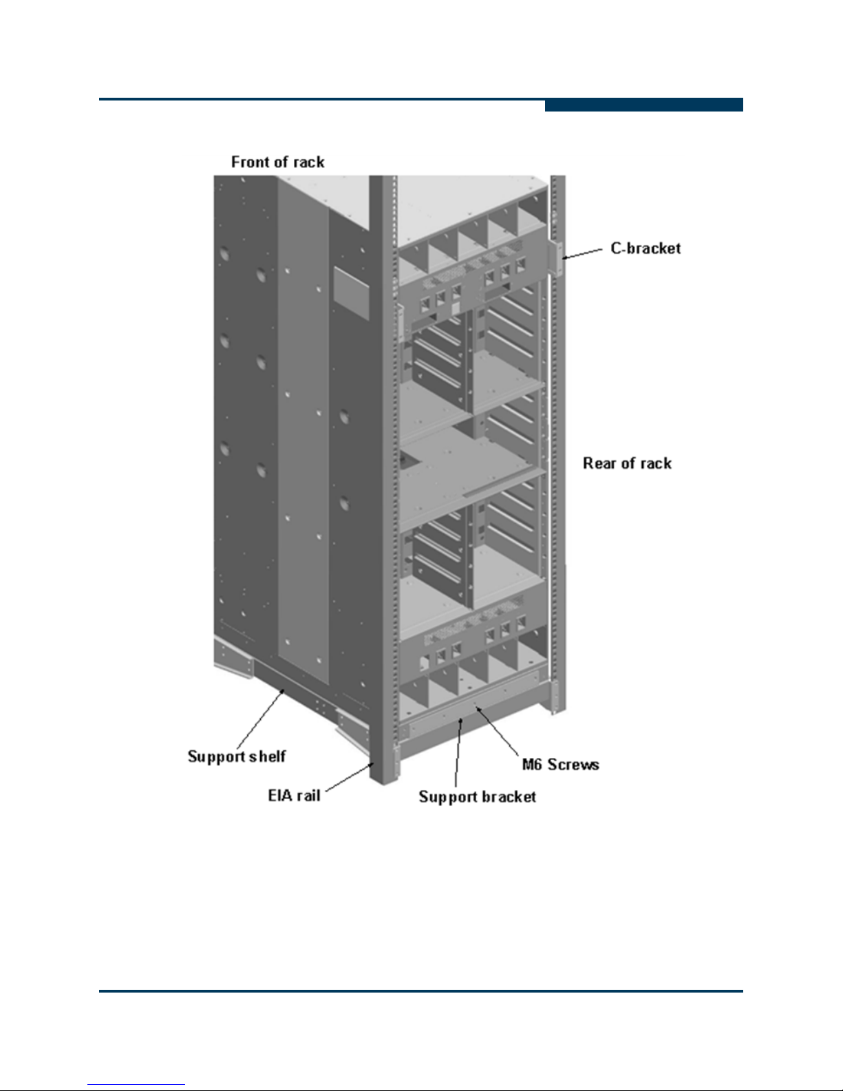
3. Attach the support bracket to the support shelf and fasten with seven (7)
S
#10-32 flat head screws. Torque screws to 30in-lb.
Figure 1-31 Support Shelf Assembly
1-38 D000140-001 B
Page 47

A
Installation
12800-360 Installation
4. Install the support shelf into the rack. Fasten the M6 screws to pre-installed
clip nuts and torque to 30 in-lb. There are three (3) screws per mounting
bracket.
Figure 1-32 Attaching the Support Shelf to the Rack
5. Orient and position the chassis for installation in the rack.
D000140-001 B 1-39
Page 48

Installation
12800-360 Installation
WARNING!!
To avoid injury, do not lift manually. Use a mechanized lift only.
S
Chassis only:
90kg (197lbs)
Fully-loaded:
244kg (535lbs)
1-40 D000140-001 B
Page 49

A
Installation
12800-360 Installation
6. Orientation of the chassis on a pallet: The chassis has been packaged on
sliding surfaces to facilitate installation in a rack by sliding off of the pallet
and on the support shelf. Remove the rear foam block to expose sliding
surfaces. The rear of the chassis is oriented towards a cutout in the bottom
tray.
Figure 1-33 Loading from the Pallet
D000140-001 B 1-41
Page 50

Installation
12800-360 Installation
7. Position the chassis on front on the rack. Use pallet jack to move the
S
chassis. Orient the chassis on a pallet in front of the rack as shown. Chassis
rear should be facing front of the rack. For installations in racks arranged in
rows, distance between adjacent rows of racks (width on a cold isle) should
be greater than 36" to be able to move the chassis on a pallet through a cold
isle.
Figure 1-34 Positioning the Switch
1-42 D000140-001 B
Page 51

A
Installation
12800-360 Installation
8. Installing the chassis in the rack: Align the chassis with the rack. Raise the
chassis using a pallet jack such that the bottom of the chassis is at or slightly
higher than the top surface of the support shelf pre-installed in the rack.
Lock the pallet jack wheels. Use a group of people to push the chassis from
the front to slide it off the pallet and on the support shelf. The chassis should
be inserted into the rack until the rear of the chassis base is against the rear
support bracket.
Figure 1-35 Sliding the Switch off the Pallet
D000140-001 B 1-43
Page 52

Installation
12800-360 Installation
9. Fasten the front of the chassis to the rack by installing the front support
Figure 1-36 Fasten the Chassis to the Front of the Rack
S
bracket and fasten to the base of the chassis with five (5) M6 screws. Fasten
to the support shelf with seven (7) #10-32 screws. Torque to 30 in-lb.
10. Fasten the rear of the chassis to the rack: Fasten the rear support bracket to
the base of the chassis with five (5) M6 screws. Torque to 30 in-lb.
11. Install two (2) C-brackets by sliding over the H-brackets that are pre-installed
on the chassis.
1-44 D000140-001 B
Page 53
A
Installation
12800-360 Installation
Figure 1-37 Fasten the Chassis to the Back of the Rack
D000140-001 B 1-45
Page 54

Installation
12800-360 Installation
12. Attach the cable management guides.
S
If applicable, attach the cable management guides to the front and rear EIA
mounting rails, and fasten with M6 screws to the pre-installed clip nuts. The
guides should be installed such that the wireframe supports line up with the
chassis leaf module slots. There are four (4) guides in the front of a rack and
four (4) in the rear of a rack.
Figure 1-38 Attaching Cable Management Guides
13. If applicable, replace the door(s) on the rack.
1-46 D000140-001 B
Page 55

Installation
A
Connect Equipment to the Ports and Power On the System
Connect Equipment to the Ports and Power On
the System
NOTE:
Before connecting equipment, it is important to understand the locations of
the serial and Ethernet ports on the 12200, 12300 and 12800 series. For the
12200 and 12300, these are located on the switch IB port side. For the 12800
series, these are located on the Serial, Ethernet, Chassis EEPROM Board
(SEEB) modules. Each SEEB module communicates with a Management
Module (MM) on the opposite side of a 12800 chassis.
Figure 1-39 12200 and 12300 Serial and Ethernet Ports
Figure 1-40 12800 Series Serial and Ethernet Ports (SEEB Module)
D000140-001 B 1-47
Page 56

Installation
Connect Equipment to the Ports and Power On the System
1. Connect a Category 5 or 6 (Cat 5/6) Ethernet cable to the RJ-45 connector(s)
on the switch. Connect the other end of the Cat 5/6 to an OOB LAN workstation,
another switch or a hub.
2. Connect the switch to IB-enabled host(s)/switch(es) using QDR QSFP IB
cables, or to DDR host(s)/switch(es) using a QSFP-CX4 cable.
NOTE:
Make sure all cables latch securely into the corresponding port connectors.
If the IB cable connector is not properly oriented to fit onto the port
receptacle (i.e., while attempting to insert the cable in the port), do not twist
the connector to achieve the correct orientation. Instead, reach back a few
feet on the cable, and twist the bulk cable to allow the connector to rotate to
the proper orientation. Doing this prevents all of the rotational forces from
acting right at the connector terminations.
CAUTION!
It is important to provide strain relief for the IB cable connector.
S
Connecting Power
NOTE:
For each power supply installed, a power cord must be installed in
corresponding power inlet.
1. Provide strain relief for the power cable(s).
2. If necessary, replace the fascia(s) over the switch fans.
3. Connect the power cables to a power distribution unit (PDU) or a proper AC
power outlet.
4. When the switch is plugged into an AC power outlet:
a. The system powers up.
b. The fans start.
c. The system performs a power-on self test (POST).
NOTE:
For the 12800 switches, make certain the DC On switch is illuminated. If it is
not, press the button to supply power.
5. The switch, power supply, and fan LEDs light up.
1-48 D000140-001 B
Page 57

A
Bringing Up the System For the First Time
Bringing Up the System For the First Time
Start-up Procedures
1. Power up the switch.
2. From its flash image on the management module, the switch begins its boot
process.
NOTE:
If the DB9 port of the SEEB module or the RS232 port on the 12200/12300 is
connected to a terminal emulation program, the user will be able to view the
switch boot process. Be certain to use a null-modem/crossover serial cable
for the console port. For users assembling their own cable, refer to
Appendix C for serial port pinout information. The settings for the terminal
emulation device should be:
•8 data bits
•no parity bits
Installation
• 1 stop bit
• 57.6K baud
• Use VT100 emulation.
• Flow control = XON/XOFF
3. Verify the IP address with the command line interface (CLI) command
showChassisIpAddr command. The system returns the information similar
to the following:
Chassis IP Address: 192.168.100.9 Net mask: 255.255.240.0
Changing the Switch IP Address and Default Gateway via the
CLI
The command line interface (CLI) can be accessed via Telnet, SSH, the SEEB
module DB-9 or 12200/12300 RS-232 serial port(s).
1. Determine the CLI access method (i.e., Telnet, SSH, or Serial).
D000140-001 B 1-49
Page 58

Installation
Bringing Up the System For the First Time
NOTE:
If using a serial port, skip to Step 6. Steps 2 through 5 are for those users
accessing the switch via Telnet or SSH. For the 12800 series, make certain
to connect to the SEEB serial port associated witht the Master Management
Module (MM). These are:
• 12800-040: MM 201
• 12800-120: MM 207
• 12800-180: MM 211
• 12800-360: MM 227
2. Connect appicable serial cables to the RS-232/DB-9 ports of the switch.
Connect the other end to a workstation. If using a terminal emulation device,
the settings should be:
•8 data bits
•no parity bits
S
• 1 stop bit
• 57.6K baud
• Use VT100 emulation.
• Flow control = XON/XOFF
3. If using Telnet or SSH, access the switch with the following command:
open 192.168.100.9
4. The system prompts for a user name. In order to change the IP address and
default gateway, the user must be logged in as the administrator. At the prompt
enter:
admin
5. The system prompts for a password. At the prompt enter:
adminpass
The system responds with:
Welcome to the <SWITCH> CLI. Type 'list' for the list of
commands.
6. To change the switch IP address enter:
setChassisIpAddr -h ipaddress -m netMask
where -h ipaddress is the new IP address in dotted decimal (i.e.,
xxx.xxx.xxx.xxx) format, and -m netMask is the new subnet mask in dotted
decimal (i.e., xxx.xxx.xxx.xxx) format.
1-50 D000140-001 B
Page 59

A
7. To change the switch default gateway IP address enter:
setDefaultRoute -h ipaddress
where -h ipaddress is the new default gateway IP address in dotted decimal
(i.e., xxx.xxx.xxx.xxx) format.
8. To to exit the CLI enter:
logout
Bringing Up the System For the First Time
Updating the Management Module IP Addresses in a
Redundant Management Configuration (12800-040,
12800-120, 12800-180 and 12800-360)
Each management module must have a unique IP address that is different than the
chassis IP address of the switch. Therefore, a redundantly-managed switch will
have multiple unique IP addresses.The default IP addresses are:
12800-040
• Chassis: 192.168.100.9
Installation
• Management Module 201: 192.168.100.10
• Management Module 202: 192.168.100.11
12800-120
• Chassis: 192.168.100.9
• Management Module 207: 192.168.100.10
• Management Module 208: 192.168.100.11
12800-180
• Chassis: 192.168.100.9
• Management Module 211: 192.168.100.10
• Management Module 212: 192.168.100.11
12800-360
• Chassis: 192.168.100.9
• Management Module 227: 192.168.100.10
• Management Module 228: 192.168.100.11
It is necessary for each management module to have a unique IP address for the
following reasons:
• Unique IP addresses are used when sending syslog messages from a managed
spine to a syslog server.
• Gives the user the ability to ping each management spine separately.
D000140-001 B 1-51
Page 60

Installation
Bringing Up the System For the First Time
• If the IP addresses are not unique, collisions will occur, causing IP operations to
fail.
To update the IP address on a management module, do the following:
1. Ensure that the module is connected to a COM port on a serial terminal device
via the RS-232 port (12200/12300) or DB-9 port (12800 series).
2. Get to a [boot]: prompt by following Step a or b.
a. If the management module is running and displays the -> prompt, enter the
following command at the console:
reboot now
Then press Enter.
b. If the module is not running, power on the switch.
3. When the system displays image1 or image2, press the Spacebar to interrupt
the auto load sequence before the counter expires (within 5 seconds).
4. At the [boot]: prompt type the following:
S
moduleip <NEW IP ADDRESS>
Then press Enter.
NOTE:
For versions previous to 5.0.2, use the command
NOTE:
This command changes the IP address for image1 and image2 on each
module.
5. At the [boot]: prompt enter reboot, and press Enter. Upon reboot the IP
address is changed. Repeat for the second Management Module.
Enabling 8X Ports
Users can enable 8X (10 Gbps) ports by combining two (2) 4X ports together (also
known as a “DUO”). The first port in a DUO is known as the master port; the second
port is the partner or slave port. The following CLI commands can enable 8x ports:
ismPortSetWidth: sets the supported link width for an individual IB port.
ismChassisSetWidth: sets the supported link width for all chassis IB
ports.
ismIslSetWidth: sets the supported link width for all interswitch link (ISL)
IB ports. This command is only available 12800-series switches.
spineip.
NOTE:
This section focuses on enabling 8x external cable ports. For details on
1-52 D000140-001 B
Page 61
A
each command, refer the QLogic 12000 CLI Reference Guide.
Creating an 8x Port: 12200/12300
For the 12200 and 12300 switches, 8x DUOs are set up by combining the 4X port
on the bottom row with the 4X port directly above it (e.g., port 1 with port 19, port 2
with 20, port 3 with port 21, etc.):
Figure 1-41 12200/12300 8x DUOs
Installation
Bringing Up the System For the First Time
For example, to combine ports 2 and 20:
1. Log into the switch CLI with the login admin and password adminpass.
2. Enable port 2 with a command similar to:
ismPortSetWidth Cable02 7 -bounce.
and press Enter.
3. Enable port 20 using same command as above, changing the port number
(i.e., Cable20).
4. At the switch, unplug and reinsert the cables to the physical ports. After
reinserting the first cable, the user has four (4) seconds to reinsert the
second cable associated with the 8x connection before the link begins
training.
NOTE:
For proper 8x functionality, it is required that both QSFP cables for a DUO
D000140-001 B 1-53
Page 62

Installation
Bringing Up the System For the First Time
are from the same manufacturer, as well as the same length.
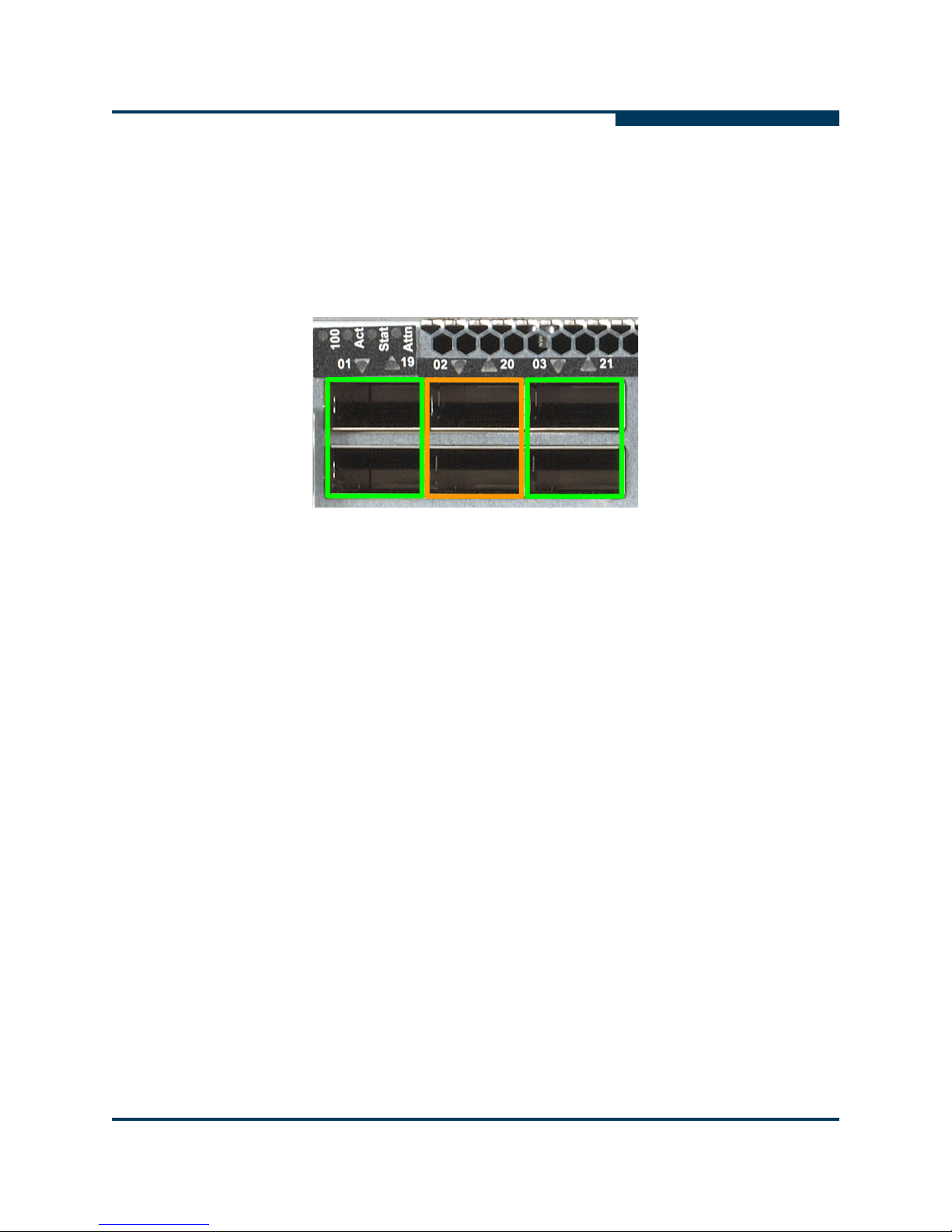
5. After reinserting the cables, bring up Chassis Viewer. The 8X ports are
displayed as shown in Figure 1-42 where both ports of the DUO have LEDs
on.
Figure 1-42 8X Ports Enabled
6. From the Chassis Viewer main menu, click on Port Stats then IB Port Stats
to display the IB Port Statistics screen. The 8X port (for DUO of cable ports
10 and 28) is displayed as shown in Figure 1-43:
Figure 1-43 8X Port Statistics
S
The first port of the group (port 10) is shown as active and Up, while the other
port in the DUO (port 28) is displayed as down and Disabled.
1-54 D000140-001 B
Page 63

A
Creating an 8x Port: 12800 Series
For the 12800 switches, 8x DUOs are set up on the leaf modules as follows:
UHP Leaf (18 4x QDR ports): combine the 4X port on the bottom row with the 4X
port directly above it (e.g., port 1 with port 10, port 2 with 11, port 3 with port 12,
etc.).
UHD Leaf (24 4x QDR ports): for ports 1 through 18, combine the 4X port on the
bottom row with the 4X port directly above it (e.g., port 1 with port 10, port 2 with
11, port 3 with port 12, etc.). For ports 19 through 24 DUOs are made by combing
the ports sequentially (i.e., port 19 and port 20, port 21 and port 22, and port 23
and port 24).
Figure 1-44 12800 Leaf Module 8x DUOs
Installation
Bringing Up the System For the First Time
For example, to combine ports 8 and 17 on UHP leaf 111 in a 12800-180 switch:
1. Log into the switch CLI with the login admin and password adminpass.
2. Enable port 8 with a command similar to:
ismPortSetWidth L111P08 7 -bounce.
and press Enter.
3. Enable port 17 using same command as above, changing the port number
(i.e., L111P17).
4. At the switch, unplug and reinsert the cables to the physical ports. After
reinserting the first cable, the user has four (4) seconds to reinsert the
second cable associated with the 8x connection before the link begins
training.
D000140-001 B 1-55
Page 64

Installation
Bringing Up the System For the First Time
NOTE:
For proper 8x functionality, it is required that both QSFP cables for a DUO
are from the same manufacturer and the same length.
5. After reinserting the cables, bring up Chassis Viewer. The 8X ports are
displayed as shown in Figure 1-45 where both ports of the DUO have LEDs
on.
Figure 1-45 8X Ports Enabled
6. From the Chassis Viewer main menu, click on Port Stats then IB Port Stats
to display the IB Port Statistics screen. The 8X port (for DUO of cable ports 8
and 17) is displayed as shown in Figure 1-46:
S
Figure 1-46 8X Port Statistics
1-56 D000140-001 B
Page 65

A
Installation
Bringing Up the System For the First Time
The first port of the group (port 8) is shown as active and Up, while the other
port in the DUO (port 17) is displayed as down and Disabled.
D000140-001 B 1-57
Page 66

Installation
Component LEDs
Component LEDs
Management Module
Figure 1-47 Management Module LEDs
Module Status
The status LED indicates one of the following conditions:
S
• Steady Green - the module is operating normally.
• Blinking Green - LED test state.
• Off - module is in the removable state.
Module Attention
The Attention LED indicates one of the following conditions:
• Off - the system functioning normally.
• Steady Amber - the system requires some attention, which could indicate one
of the following conditions:
• The switch temperature is at a warning level on the module.
• The switch silicon temperature is at a warning level (approximately 90 degrees
• DC voltages on the board are slightly out of tolerance (12V Bulk, 5V, 3.3V
• The module can no longer function properly. The system will take the
• Blinking Amber (once every four seconds) - LED test state, which could indicate
one of the following conditions:
C).
and 1.8V are all monitored).
appropriate actions to ensure that no damage is done to its components.
• Bulk power is stable.
• The module DC-to-DC converter is enabled.
• The module is not removable.
1-58 D000140-001 B
Page 67

A
Chassis Status and Attention
The chassis status LED is Green when the system is functioning normally.
The chassis status LED is Amber when one of the following conditions exists:
• Any Fan Alarm is amber.
• Any power supply AC OK LED is off.
• Any power supply DC OK LED is off
• Any spine module Attention LED is on, or it has been determined that a spine is
not functioning (even if it is unable to light the LED).
• Any leaf module Attention LED is on, or it has been determined that a leaf is not
functioning (even if it is unable to light the LED).
The chassis status LED is Amber when the system can no longer function properly
and indicates one of the following conditions:
• No functional fan trays are present.
• No functional spines are present.
Installation
Component LEDs
• No functional leaves are present.
The chassis status LED is off when:
• There are no functional power supplies present.
• There are no management cards in the system
• AC power has been removed from the system.
Fault Tolerant
The Chassis Fault Tolerant (FT) LED indicates the following condition:
• Steady Green - the chassis is populated with a full complement of fans as well
as N+1 power.
Service Required
The Chassis Service Required (SVC) LED is not currently implemented.
Master
The Master LED is Green when module is acting as the master Management Module
(i.e., it is the master MM).
D000140-001 B 1-59
Page 68

Installation
Component LEDs
MRL Active
S
The MRL Active LED is Green when mechanical release latch (MRL) thumbscrew
is secured to the Serial, Ethernet, Chassis EEPROM Board (SEEB).
Figure 1-48 MRL Active LED
1-60 D000140-001 B
Page 69

A
Leaf Module
Installation
Component LEDs
Figure 1-49 Leaf Module LEDs
IB Port LEDs
Each module IB port has a Green IB link status LED that provide the following
indications:
• On - the logical link is up (port is in the Active state).
• Off - the physical link is down (port is in the Down state).
Module Status
The status LED indicates one of the following conditions:
• Steady Green - the module is operating normally.
• Blinking Green - LED test state.
• Off - module is in the removable state.
Module Attention
The Attention LED indicates one of the following conditions:
D000140-001 B 1-61
Page 70

Installation
Component LEDs
• Off - the system functioning normally.
• Steady Amber - the system requires some attention, which could indicate one
of the following conditions:
• The switch temperature is at a warning level on the module.
• The switch silicon temperature is at a warning level (approximately 90 degrees
• DC voltages on the board are slightly out of tolerance (12V Bulk, 5V, 3.3V
• The module can no longer function properly. The system will take the
• Blinking Amber (once every four seconds) - LED test state.
Spine Module
Figure 1-50 Spine Module LEDs (Double Spine Shown)
S
C).
and 1.8V are all monitored).
appropriate actions to ensure that no damage is done to its components.
Module Status
The status LED indicates one of the following conditions:
• Steady Green - the module is operating normally.
• Blinking Green - LED test state.
• Off - module is in the removable state.
Module Attention
The Attention LED indicates one of the following conditions:
• Off - the system functioning normally.
• Steady Amber - the system requires some attention, which could indicate one
of the following conditions:
• The switch temperature is at a warning level on the module.
1-62 D000140-001 B
Page 71

A
• The switch silicon temperature is at a warning level (approximately 90 degrees
• DC voltages on the board are slightly out of tolerance (12V Bulk, 5V, 3.3V
• The module can no longer function properly. The system will take the
• Blinking Amber (once every four seconds) - LED test state.
SEEB Module
Installation
Component LEDs
C).
and 1.8V are all monitored).
appropriate actions to ensure that no damage is done to its components.
Figure 1-51 SEEB Module LEDs
RJ45 LEDs
The RJ45 connectors have two LEDs, Act and 100. The 100 LED is Green when
a 100Mbps link is connected. The Act LED is Amber when an Ethernet link has
been established, and blinking when the link is active.
MRL Active
The MRL Active LED is Green when the mechanical release latch (MRL) thumbsrew
is secured to the Serial, Ethernet, Chassis EEPROM Board (SEEB) and a
Management Module is installed in the front of the chassis.
D000140-001 B 1-63
Page 72

Installation
Component LEDs
12200 and 12300
S
Figure 1-52 12200 and 12300LEDs
IB Port LEDs
Status
Attention
Each module IB port has a Green IB link status LED that provide the following
indications:
• On - the logical link is up (port is in the Active state).
• Off - the physical link is down (port is in the Down state).
The status LED indicates one of the following conditions:
• Steady Green - the module is operating normally.
• Blinking Green - LED test state.
• Off - module is in the removable state.
The Attention LED indicates one of the following conditions:
• Off - the system functioning normally.
• Steady Amber - the system requires some attention, which could indicate one
of the following conditions:
• The switch temperature is at a warning level on the module.
• The switch silicon temperature is at a warning level (approximately 90 degrees
C).
1-64 D000140-001 B
Page 73

A
• DC voltages on the board are slightly out of tolerance (12V Bulk, 5V, 3.3V
and 1.8V are all monitored).
• The module can no longer function properly. The system will take the
appropriate actions to ensure that no damage is done to its components.
• Blinking Amber (once every four seconds) - LED test state.
RJ45 LEDs
The RJ45 connectors have two LEDs, Act and 100. The 100 LED is Green when
a 100Mbps link is connected. The Act LED is Green when an Ethernet link has
been established, and blinking when the link is active.
12800 Fans and Power Supplies
Fan LEDs
Figure 1-53 12800 Fan LEDs
Installation
Component LEDs
Fan LEDs indicate the following status(es):
• Green indicates that the fan is functioning properly.
• Amber indicates that the following warning condition exists:
• A single fan failure when the rotation speed is less than 4000 RPM or greater
than 10950 RPM.
D000140-001 B 1-65
Page 74

Installation
Component LEDs
• Green and Amber on indicates a possible problem, including:
• The fan tray is not responding to commands for configuration and
temperature-related operations.
• A fan is not responding to commands for temperature and speed related
operations.
• The fan speed has fallen below the minimum allowed RPM for a fan.
Power Supply LEDs
S
Figure 1-54 12800 Power Supply LEDs
Each power supply has three LEDs: DC OK, AC OK and Alarm. Following are the
status definitions for each.
DC OK
• Green indicates that DC power is normal.
• Off indicates a DC power failure or no DC power is present.
AC OK
• Green indicates that AC power is normal.
• Off indicates a AC power failure or no AC power is present.
Alarm
• Amber indicates a fault condition, failed fan, over temperature condition.
1-66 D000140-001 B
Page 75

Installation
A
Switch-Based QLogic Fabric Manager License Key
Switch-Based QLogic Fabric Manager License
Key
If purchased, certain packages of the InfiniBand Fabric Suite entitle the user to the
switch-based QLogic Fabric Manager. Refer to the licensing documentation that
comes with the InfiniBand Fabric Suite for instructions on generating the license key.
Figure 1-55 InfiniBand Fabric Suite Licensing Information
D000140-001 B 1-67
Page 76

Installation
Switch-Based QLogic Fabric Manager License Key
Procedures
1. Record the IFS serial number.
2. Go to the QLogic Feature Activation/License Key web site
http://lk.qlogic.com
Figure 1-56 License Key Activation Center 1
.
S
3. Enter the InfiniBand Fabric Suite serial number. Click Continue. The system
validates the serial number and displays the following screen:
Figure 1-57 License Key Activation Center 2
1-68 D000140-001 B
Page 77

A
Installation
Switch-Based QLogic Fabric Manager License Key
4. Click Activate License Key and click Continue. The following screen is
displayed:
Figure 1-58 License Key Activation Center 3
D000140-001 B 1-69
Page 78

Installation
Switch-Based QLogic Fabric Manager License Key
5. Enter your email address in the Email: and Confirm Email: text boxes.
Click Continue. The following screen is displayed:
Figure 1-59 License Key Activation Center 4
S
1-70 D000140-001 B
Page 79

A
Installation
Switch-Based QLogic Fabric Manager License Key
6. Enter all applicable information. For the City: and/or the Zip/Postal Code
entries, click on the flashlight hyperlinks. The following is displayed:
Figure 1-60 License Key Activation Center 5
7. In the City: and Zip: text boxes, enter the applicable information and click
Search. Alternatively, search through the list of cities, click the applicable
radio button, then click Search. The following is displayed:
Figure 1-61 License Key Activation Center 6
D000140-001 B 1-71
Page 80

Installation
Switch-Based QLogic Fabric Manager License Key
8. If the information is correct, click Close. The following screen is displayed:
Figure 1-62 License Key Activation Center 7
S
1-72 D000140-001 B
Page 81

A
Installation
Switch-Based QLogic Fabric Manager License Key
9. Click Continue. The following screen is displayed:
Figure 1-63 License Key Activation Center 8
10. In the GUID: text box, enter the FRU GUID of the following applicable
components:
QLogic 12300 chassis
QLogic 12800 series Management Module to be used as the master
subnet manager
Master and redundant switch-based QLogic Fabric Manager
Click Continue. A license key will be emailed.
D000140-001 B 1-73
license keys can be generated by entering the GUID of the
primary and redundant management modules in the GUID: text
boxes.
Page 82

Installation
Switch-Based QLogic Fabric Manager License Key
NOTE:The FRU GUID can be found:
On the label of each FRU.
Using the Chassis Viewer, the View FRU button for each
applicable chassis or module FRU.
For the12300 via the switch Command Line Interface (CLI), using
the command showIBNodeDesc.
For the 12800 series via the switch Command Line Interface
(CLI), using the command ShowInventory. From the system
output, locate the GUID of the Management Module that will be
used to apply the license key.
S
1-74 D000140-001 B
Page 83

A
QLogic 12000 Six-Port Upgrade
Users can order a six-port License Key upgrade for the QLogic 12300-BS18
advanced 40Gb/s QDR InfiniBand switch. Refer to the licensing documentation that
comes with the QLogic 12300-BS18 switch for instructions on generating the license
key.
Figure 1-64 InfiniBand Fabric Suite Licensing Information
Installation
QLogic 12000 Six-Port Upgrade
D000140-001 B 1-75
Page 84

Installation
QLogic 12000 Six-Port Upgrade
Procedures
1. Record the 12300-BS18 serial number.
2. Go to the QLogic Feature Activation/License Key web site
http://lk.qlogic.com
Figure 1-65 License Key Activation Center
S
.
3. Enter the 12300-BS18 serial number. Click Continue. The system validates
the serial number and moves to the next screen.
4. Click Activate License Key and click Continue.
5. Enter your email address in the Email: and Confirm Email: text boxes.
Click Continue.
6. Enter all applicable contact information. Click Continue.
7. Enter the transaction code and switch GUID, then click Continue.
NOTE:The FRU GUID can be found:
On the label of each 12300-BS18 switch.
Using the Chassis Viewer, the View FRU button for each
applicable chassis.
For the12300-BS18 via the switch Command Line Interface
(CLI), using the command showIBNodeDesc.
8. If the information displayed is correct, click Yes.
9. Review the end-user license agreement, then click Agree.
10. The screen displays the generated license key, along with the updated port
count status. To send this information to another user, enter an email
address and click Send. When finished, click Done.
1-76 D000140-001 B
Page 85

A QLogic 12000 Series
Product Specifications
Physical Specifications
All products within the 12200, 12300 and 12800 Director series are designed to be
installed in industry-standard 19-inch four-post server racks.
Racks should conform to conventional standards. Use the American National
Standards Institute (ANSI)/Electronic Industries Association (EIA) standard
ANSI/EIA-310-D-92 and International Electrotechnical Commission (IEC) 297.
These racks are commercially available in various depths. It is recommended to
use rack with minimum of 36" depth to facilitate cable installation and routing. Other
physical attributes are shown in the table below.
NOTE: The 12000 series products should not be installed in two-post
telecommunication racks.
Table A-1. 12000 Physical Attributes
Model # 12200 12300 12800-040 12800-120 12800-180 12800-360
Height (rack
units/inches)
Depth
(without
cables)
Width 17.32" (440mm)
Max weight
(lb./kg.)
D000140-001 B A-1
1U/1.75" 1U/1.75" 5U/8.75” 10U/17.5" 14U/24.5" 29U/50.7”
24” 25 3/4" (654mm)
15/6.8 26/11.8 100/45.5 155/70.5 285/129.3 536/243.1
Page 86

QLogic 12000 Series Product Specifications
Environmental Specifications
Environmental Specifications
Operating temperature:
5° - 40°C at sea level, altitude derating 1°C per 300m to 2,400m
Non-operating temperature:
-40°C to 65°C
Relative humidity (non-condensing):
Operating 5% - 85%; Non-operating 5% - 90%
12200 and 12300
Cooling and Thermal Management:
Cooling:
Air cooled with a hot plug fan/power tray, three fans per tray, 40mm,
12VDC (12300)
S
Power
Four fans, no fan trays (12200)
Front-to-back airflow
NOTE:
The 12200 also offers a reversed airflow model
Power Supply:
Two redundant, hot plug fan/power supplies (12300)
90/264 VAC operation
275W max power per supply
Input: 90–264V AC, 47–63Hz, 1 Phase, 3.6A max current at 100VAC
Inrush Current: 13A @ 115VAC, 6.5A @ 230VAC
Power Factor: 95% @ 230VAC, 50% load
Power Inlet Plug: two IEC 320-c14 connectors for independent AC
inputs (12300)
A-2 D000140-001 B
Page 87

A
12800 Series
All 12800 series switches use the same fan tray modules -- intake and exhaust -and share the same thermal management attributes listed below. The quantity of
fan tray modules used in each system is defined in the following table:
Maximum
InfiniBand
Ports
Maximum
Leaf Modules
QLogic 12000 Series Product Specifications
12800 Series
Table A-2. 12800 Product Configurations
Model # 360 180 120 040
864 432 288 96
36 18 12 4
Maximum
Spine
Modules
Management
Modules
Fan Trays
(Intake/
Exhaust)
Power
Supplies
• Fan Tray:
Hot plug with one axial, brushless, 12V fans per Fan Tray
• Chassis airflow:
Front-to-back
• Power supply airflow:
Front to back
NOTE:It is recommended that the 120, 180 and 360 be installed as
follows:
Intake fan side towards the cold aisle
9 Double 4 Double,
1 Single
2 2 2 2
10/10 5/3 5/3 4/0
12 6 4 4
2 Double,
1 Single
1 Double
Exhaust fan side towards the hot aisle
• Thermal management:
Temperatures of all major heat producing components are continuously
monitored by system management modules. Fan speed is monitored and
automatically adjusted by system management modules to maintain
D000140-001 B A-3
Page 88

QLogic 12000 Series Product Specifications
12800 Series
appropriate temperatures of major heat producing components. Monitoring
is performed via a two wire I2C interface to each Fan Tray.
Power Specifications
All products within the 12800 series use a common switching power supply. System
power attributes are shown in the table below. Power supplies are are N+1
redundant and hot pluggable.
NOTE:
An AC power cord is required for each power supply. Refer to the table
below.
Table A-3. System Power Attributes
Model # 12800-360 12800-180 12800-120 12800-040
Maximum # of
Power
Supplies
Maximum
wattage, fully
configured
Minimum
required
power
supplies
Power
supplies
required for
DC (N+1)
redundancy
Power
supplies
required for
AC
redundancy
Maximum
output per
supply
Input voltage 90-264 VAC autoranging
Input
frequency and
phase
S
12 6 4 4
7,455 3,654 2,735 922
6 3 3 2
7 4 3 2
12 6 4 2
1200 Watts
47-63 Hz
A-4 D000140-001 B
Page 89

A
QLogic 12000 Series Product Specifications
Table A-3. System Power Attributes
Model # 12800-360 12800-180 12800-120 12800-040
Maximum
current per
supply
Inrush Current 30Amps Max
Power Factor
efficiency
Power Inlet
connector
# of Power
Inlets
Power Cord
connector
12 6 4 4
100Amps
99% @ 230V, full load
IEC320-C20
IEC320-C19
12800 Series
D000140-001 B A-5
Page 90

QLogic 12000 Series Product Specifications
12800 Series
Power Distribution Guidelines
The following section details power distribution guidelines and recommendations
for the QLogic 12800 series.
The power supplies for the 12800 series has a maximum inlet current of
15amps @ 110volts and 6amps @ 220volts. Please observe power outlet,
power strip and extension cable ratings.
Do not exceed 80% of the ampere rating limit of the power outlet, power
strip or an extension cable that the equipment is plugged into. As such, the
power delivery system must be that the power supplies do not overpower
the maximum amperage of any given system. For the 12800-360 and
12800-180 it is recommended to power the systems over 220 volts.
CAUTION!
High-powered systems, such as the 12800-180 and 12800-360 can
place significant loads on power distribution units (PDUs) and
uninterupable power supplies (UPSs). It is recommended to measure
the total amperage and power that a PDU or UPS needs to handle.
S
Figure A-1 12800-Series Power Distribution
A-6 D000140-001 B
Page 91

A
QLogic 12000 Series Product Specifications
12800 Series
Table A-4. AC Plug Types
Volta g e
Region/Country
North America 100-127 NEMA 5-20P
North America 200-240 NEMA
North America 200-240 NEMA
Europe (Schuko) 200-240 CEE 7/7 Used in Austria, Belgium,
International 200-240 IEC 309 3-wire (two-phase & earth).
Internationalt 200-240 IEC 309 4-wire (three-phase & earth).
International 200-240 IEC 309 5-wire (three-phase, earth &
Rating
Plug Type Misc/Notes
L6-20P
Three phase AC
L15-30P
Finland, France, Germany,
Greece, Hungary, Indonesia,
The Netherlands, Norway,
Poland, Portugal, Russia,
Spain, Sweden.
Connector size and color
variations are used to indicate
amperage rating. This is utilized
in Switzerland for 16A
applications.
Connector size and color
variations are used to indicate
amperage rating.
neutral). Connector size and
color variations are used to
indicate amperage rating.
D000140-001 B A-7
Page 92

QLogic 12000 Series Product Specifications
12800 Series
Notes
S
A-8 D000140-001 B
Page 93

B Safety and Regulatory
Compliance Information
This section provides regulatory compliance, safety and electromagnetic
compatibility (EMC) information for the QLogic 12000 series products.
Safety Information
Statement 1:
Disconnect Device - This unit may have more than one power cord. To reduce the
risk of electrical shock, disconnect all power cords before servicing unit.
Verklaring 1:
Apparaat loskoppelen - Deze eenheid heeft mogelijk meer dan een stroomkabel.
Verminder het risico op een elektrische schok door alle stroomkabels los te koppelen
voordat u onderhoud pleegt aan de eenheid.
Varoitus 1:
Irrota laite. Yksikössä saattaa olla useampia kuin yksi virtajohto. Irrota kaikki
virtajohdot ennen yksikön huoltamista, niin sähköiskun vaara pienenee.
Déclaration 1 :
Déconnecter l'appareil - Cette unité peut disposer de plusieurs cordons
d'alimentation. Déconnectez tous les cordons d'alimentation avant son entretien
pour réduire le risque d'électrocution.
Anweisung 1:
Gerät trennen - Diese Komponente verfügt möglicherweise über mehrere
Netzkabel. Trennen Sie alle Netzkabel bevor Sie die Komponente warten, um die
Gefahr eines elektrischen Schlags zu vermeiden.
D000140-001 B-1
Page 94

Safety and Regulatory Compliance Information
Safety Information
Dichiarazione 1:
Scollegare il dispositivo - L'unità potrebbe avere più di un cavo di alimentazione.
Per ridurre il rischio di scosse elettriche, scollegare tutti i cavi di alimentazione prima
di intervenire sull'unità.
Erklæring 1:
Frakobling av enheten - denne enheten kan ha mer enn én strømledning. For å
redusere faren for elektrisk sjokk, må alle strømkablene trekkes ut før enheten
vedlikeholdes.
Declaração 1:
Desligar dispositivo - Esta unidade pode ter mais de um cabo de alimentação. Para
reduzir o risco de choque eléctrico, desligue todos os cabos de alimentação antes
de fazer a manutenção da unidade.
Declaración 1:
Desconexión de dispositivo - Esta unidad puede tener más de un cable de
alimentación eléctrica. Para reducir el riesgo de electrocución, desconecte todos
los cables antes de realizar cualquier servicio técnico en la unidad.
S
Uttalande 1:
Koppla bort enhet. Den här enheten kan ha mer än en strömsladd. Reducera risken
för elektrisk stöt genom att koppla bort alla strömsladdar innan enheten underhålls.
Kijelentés 1:
Szüntesse meg az eszköz tápellátását – Ez az egység egynél több tápvezetékkel
rendelkezhet. Az áramütés kockázatának csökkentése érdekében minden
tápvezetéket húzzon ki az egység szervizelése elott.
Инструкция 1:
Отключите устройство – В данном устройстве может быть более одного
сетевого шнура. Во избежание поражения электрическим током отсоедините
все сетевые шнуры до проведения технического обслуживания устройства.
声明 1:
断开装置 - 此装置可能有一个以上电源电缆。为了减少电击风险,请在维修该装置
前断开所有电源电缆。
ステートメント 1:
デバイスを外してください - このユニットには複数の電源ユニットが接続され
ている可能性があります。感電のリスクを軽減するため、ユニットを修理する前
にすべての電源コードを外してください。
B-2 D000140-001
Page 95

A
Statement 2:
Chassis Lifting - Use safe practices when lifting.
NOTE: Use a team of people appropriate to the weight of each specified product
Verklaring 2:
Chassis optillen - Volg de veiligheidsinstructies bij het optillen.
ANMERKUNG: Gebruik genoeg mensen voor het gewicht van elk gespecificeerd
Safety and Regulatory Compliance Information
Safety Information
and in conjunction with applicable guidelines. Whenever possible, use a
mechanical lift.
product en hanteer de toepasselijke richtlijnen. Gebruik waar
mogelijk een mechanisch tilapparaat.
Varoitus 2:
Kotelon nostaminen. Noudata nostaessasi turvaohjeita.
HUOMAUTUS: Varaa nostamista varten laitteen painoon nähden sopiva ja
Déclaration 2 :
Soulever le châssis - Employez des mesures de sécurité pour soulever.
REMARQUE : Faites appel au nombre de personnes approprié en fonction du
Anweisung 2:
Anheben des Gehäuses - Lassen Sie Sicherheit beim Anheben des Gehäuses
walten.
ANMERKUNG: Setzen Sie jeweils dem Gewicht jedes angegebenen Produkts und
Dichiarazione 2:
Sollevamento del telaio - Durante il sollevamento, seguire le procedure di sicurezza.
sovellettavien ohjeiden mukainen määrä henkilöitä. Käytä
mekaanista nosturia aina, kun se on mahdollista.
poids de chaque produit spécifique et en conjonction avec les
directives applicables. Utilisez un relevage mécanique, si possible.
den Richtlinien entsprechend genügend Leute ein. Verwenden Sie,
wenn möglich, einen mechanischen Aufzug.
NOTA: utilizzare un gruppo di persone adeguato al peso di ogni prodotto
D000140-001 B-3
specifico e insieme alle indicazioni applicabili. Se possibile, usare
un sollevatore meccanico.
Page 96

Safety and Regulatory Compliance Information
Safety Information
Erklæring 2:
Løfting av kabinettet - utvis varsomhet ved løfting.
MERK: Bruk flere personer til bæring, avhengig av vekten til hvert enkelt
produkt og i samsvar med gjeldende retningslinjer. Bruk mekaniske
løftemekanismer når mulig.
Declaração 2:
Levantar o chassi - Utilize práticas seguras ao levantar o chassi.
AVISO: Utilize um grupo de pessoas adequado ao peso de cada produto
especificado, em conjunto com as directivas aplicáveis. Sempre
que possível, utilize um dispositivo mecânico de levantamento.
Declaración 2:
Elevación del chasis - Observe las prácticas de seguridad cuando quiera elevar el
chasis.
NOTA: utilice un grupo de gente apropiado al peso de cada producto
especificado junto con las pautas que correspondan. Siempre que
sea posible, utilice un elevador mecánico.
S
Uttalande 2:
Lyftning av chassi. Iakttag säkerhetsanvisningar vid lyft.
OBS! Använd ett team personer lämpade för vikten på varje specificerad
Kijelentés 2:
A burkolat emelése – Biztonságos eljárásokat alkalmazzon az emelés során.
MEGJEGYZÉS: Az egyes termékek súlyának megfelelo fobol álló csoportot
Инструкция 2:
Подъем корпуса – Соблюдайте технику безопасности при подъеме.
ПРИМЕЧАНИЕ:Подъем каждого конкретного устройства исходя из его веса
声明 2:
提起机箱 - 提起机箱时请采取安全措施。
produkt och i samband med gällande riktlinjer. Använd en
mekanisk lyftanordning närhelst det är möjligt.
alkalmazzon, a vonatkozó irányelvek betartása mellett. Lehetoség
szerint mindig használjon mechanikus emeloszerkezetet.
должен осуществляться несколькими лицами и в соответствии
с надлежащим инструкциям. Везде, где это возможно, следует
применять механические грузоподъемные устройства.
B-4 D000140-001
Page 97

A
注: 请按照每个具体产品的重量来使用一定的人数,并遵照适当的说
ステートメント 2:
シャーシの持ち上げ - シャーシを持ち上げる際は安全に配慮してください。
メモ : 各製品の重量に見合った人数で、適切なガイドラインに従って
Safety and Regulatory Compliance Information
Safety Information
明。可能的话,使用机械起重器。
持ち上げてください。可能な場合は、リフト機を使用してくだ
さい。
D000140-001 B-5
Page 98

Safety and Regulatory Compliance Information
Safety Information
Statement 3:
Energy Hazard - To reduce risk of electric shock, keep hands and fingers out of the
power supply bays and backplane areas.
Verklaring 3:
Stroomgevaar - Reduceer het risico op een elektrische schok door handen en
vingers weg te houden bij de voedingscompartimenten en de gebieden rond de
centrale printplaat.
Varoitus 3:
Sähköiskun vaara. Voit vähentää sähköiskuille altistumista, kun vältät
koskettamasta virtalähdepaikkoja ja keskuspiirilevyä.
Déclaration 3 :
Danger électrique - Pour réduire le risque d'électrocution, gardez vos mains hors
des baies d'alimentation et des zones destinées aux cartes de circuits imprimés.
S
Anweisung 3:
Gefahr vor elektrischem Schock - Um der Gefahr vor elektrischem Schock
vorzubeugen, halten Sie Hände und Finger den Netzteilschächten und der
Rückwand fern.
Dichiarazione 3:
Pericolo di scosse - Per ridurre il rischio di scosse elettriche, allontanare le mani e
le dita dagli alloggiamenti degli alimentatori e dalle aree della piastra base.
Erklæring 3:
Strømfare - hold fingre og hender unna strømforsyningsrom og kretskort for å unngå
elektrisk sjokk.
Declaração 3:
Risco de choque eléctrico - Para reduzir o risco de choque eléctrico, mantenha as
mãos e os dedos fora dos compartimentos da fonte de alimentação e das áreas de
backplane.
Declaración 3:
Peligro de energía - Para reducir el riesgo de electrocución, mantenga las manos
y los dedos alejados de los compartimentos de la fuente de alimentación eléctrica
y del circuito impreso central.
B-6 D000140-001
Page 99

A
Uttalande 3:
Risk för elektrisk stöt. Reducera risken för elektrisk stöt genom att hålla händer och
fingrar borta från strömförsörjningsfack och bakpanelsområden.
Kijelentés 3:
Áramütés veszélye – Az áramütés kockázatának csökkentése érdekében kezeit és
ujjait tartsa távol a tápcsatlakozóktól és a hátsó területektol.
Инструкция 3:
Опасное напряжение – Во избежание поражения электрическим током, не
прикасайтесь к клеммам электропитания и к центральнoй электроннoй плате.
声明 3:
电能危害 - 为了减少电击风险,手和指应远离电源架和印刷电路板区域。
ステートメント 3:
エネルギーの危険 - 感電のリスクを軽減するため、電源装置ベイおよびバック
プレーン周辺に手や指を近づけないでください。
Safety and Regulatory Compliance Information
Safety Information
D000140-001 B-7
Page 100

Safety and Regulatory Compliance Information
Safety Information
Statement 4:
Laser Radiation - certain optical products may emit laser radiation. Removing covers
could result in exposure to hazardous laser radiation. Radiation may be emitted
from connectors or fiber optic cables.
Verklaring 4:
Laserstraling - bepaalde optische producten kunnen laserstraling verspreiden. Het
verwijderen van dekplaten kan resulteren in blootstelling aan schadelijke
laserstraling. Straling kan worden afgegeven door connectoren of glasvezelkabels.
Varoitus 4:
Lasersäteily. Jotkut optiset laitteet saattavat päästää lasersäteilyä. Niiden suojusten
poistaminen saattaa altistaa vaaralliselle lasersäteilylle. Säteily voi tulla liittimistä
tai optisista kuitukaapeleista.
S
Déclaration 4 :
Rayonnement laser - Certains produits optiques peuvent produire un rayonnement
laser. Le retrait de capots peut engendrer une exposition à un rayonnement laser
dangereux. Ce rayonnement peut provenir des connecteurs ou des câbles en fibre
optique.
Anweisung 4:
Laserstrahlung - manche optischen Produkte geben Laserstrahlung ab. Beim
Entfernen der Abdeckungen können Sie möglicherweise gefährlicher
Laserstrahlung ausgesetzt werden. Laserstrahlung kann von Anschlüssen oder
Faseroptikkabeln abgegeben werden.
Dichiarazione 4:
Radiazione laser - Alcuni prodotti ottici potrebbero emettere la radiazione laser.
La rimozione delle coperture potrebbe causare l'esposizione alla radiazione laser
pericolosa. I connettori o i cavi in fibra ottica potrebbero emettere radiazioni.
Erklæring 4:
Laserstråling - visse optiske produkter kan gi fra seg laserstråling. Dersom dekslene
tas av, kan dette medføre utsettelse for farlig laserstråling. Strålingen kan komme
fra kontakter eller fiberoptiske kabler.
Declaração 4:
Radiação laser - Certos produtos ópticos podem emitir radiação laser. A remoção
de tampas pode resultar na exposição a níveis perigosos de radiação laser. A
radiação pode ser emitida de conectores ou de cabos de fibra óptica.
B-8 D000140-001
 Loading...