


KINETIZ 7T

Declaration of conformity
QUANTUM DESIGNS(HK) L TD.
5/F Somerset House, TaiKoo Place 979 Kings Road,
Quarry Bay, Hong Kong
declares that the product
Mainboard
KinetiZ 7T
is in conformity with
(reference to the specification under which conformity is declared in
accordance with 89/336 EEC-EMC Directive)
þ EN 55022 Limits and methods of measurements of radio disturbance
characteristics of information technology equipment
þ EN 50081-1 Generic emission standard Part 1:
Residential, commercial and light industry
þ EN 50082-1 Generic immunity standard Part 1:
Residential, commercial and light industry
European Representative:
QDI COMPUTER ( UK ) LTD QDI COMPUTER ( SCANDINAVIA ) A/S
QDI SYSTEM HANDEL GMBH QDI COMPUTER ( NETHERLANDS) B. V.
QDI COMPUTER (FRANCE) SARL QDI COMPUTER HANDELS GMBH
QDI COMPUTER (ESPANA) S.A. QDI COMPUTER (SWEDEN) AB
Signature : Place / Date : HONG KONG/2000
Printed Name : Anders Cheung Position/ Title : President

Declaration of conformity
Trade Name: QDI Computer ( U. S . A. ) Inc.
Model Name: KinetiZ 7T
Responsible Party: QDI Computer ( U. S. A.) Inc.
Address: 41456 Christy Street
Fremont, CA 94538
Telephone: (510) 668-4933
Facsimile: (510) 668-4966
Equipment Classification: FCC Class B Subassembly
Type of Product: Mainboard
Manufacturer: Quantum Designs (HK) Inc.
Address: 5/F, Somerset House, TaiKoo Place
979 Kings Road, Quarry Bay, HONG
KONG
Supplementary Information:
This device complies with Part 15 of the FCC Rules. Operation is subject to
the following two conditions : (1) this device may not cause harmful interference, and (2) this device must accept any interference received, including
interference that may cause undesired operation.
Signature : Date : 2000

CONTENTS
Facilité de vitesse Initialisation(Francais) ............................................. 1
1. Introduction................................................................. 3
Overview............................................................................................ 3
Key Features ...................................................................................... 3
Introduction to New Features .............................................................. 5
2. Installation Instructions .............................................. 7
External Connectors ................................................................. 7
PS/2 Keyboard & PS/2 Mouse Connector............................................. 7
USB1 & USB2...................................................................................... 7
USB3 & USB4...................................................................................... 7
Parallel Port Connector and Serial Port Connector ................................ 8
UART2 ..................................................................................................
Line-in jack(or Real out jack), Microphone-in jack, Speaker-out jack and
MIDI/Joystick connector ....................................................................... 8
ATX Power Supply Connector & Power Switch(POWER SW) .............. 8
Hard Disk LED Connector (HD LED) ..................................................... 9
Reset Switch (RESET)......................................................................... 9
Speaker Connector (SPEAKER)........................................................... 9
ACPI LED Connector (ACPI_LED) ......................................................... 9
GREEN LED Connector(GREEN_LED) .................................................. 9
Hardware Green Connector (SLEEP)................................................... 9
Power LED Connector(PWR_LED) ....................................................... 9
Key-lock connector(KEY_L) ..................................................................
Internal Audio Connectors(AUX,CDLIN, MODEM).................................11
Audio/Modem Riser Interface Connector(AMR) .................................. 12
Fan Connector (CPUFAN , CHSFAN, F AN3) ....................................... 10
Wake-Up On LAN (WOL)................................................................... 10
Wake-Up On Internal Modem (WOM)...................................................11
Infrared Header (IrDA)....................................................................... 12
Expansion Slots & I/O Ports description ............................................. 13
Jumper Settings ........................................................................... 13
Suspend to RAM Switch( J12) .......................................................... 13
I

CONTENTS
Clear CMOS(JCC) .................................................................................. 14
Enable/Disable onboard audio(JSD) ....................................................... 15
BIOS-ProtectEasy Jumper(JAV)............................................................. 14
Overclocking Jumper Setting (JFSB) ...................................................... 1 5
3. BIOS Description ..................................................................17
Utility Support .............................................................................. 17
AWDFLASH.EXE ................................................................................... 17
AW ARD BIOS Description........................................................... 18
Entering Setup .......................................................................................18
Load Fail-Safe Defaults ......................................................................... 18
Load Optimized Defaults........................................................................ 18
Standard CMOS Features Setup .......................................................... 18
Frequency/Voltage Control .................................................................... 32
Advance BIOS Features Setup ............................................................ 22
Advance Chipset Features Setup ........................................................ 24
Integrated Peripherals.......................................................................... 26
Power Management Setup................................................................... 28
PnP/PCI Configurations Setup .............................................................. 30
PC Health Status.................................................................................. 31
Set Supervisor/User Password ............................................................. 33
Boot with BIOS defaults ...................................................................... 33
Appendix A QDI Driver CD 2000 ............................................ 35
Appendix B Boot Logo .................................................... 37
RecoveryEasy....................................................................39
Introduction ........................................................................................... 39
Operation Process ................................................................................ 39
F AQ ...................................................................................................... 4 4
II

Caution
1. Be sure to add some Silicone Grease between the Socket A processor and FAN to keep them fully contact, meanwhile to meet the
heat sink requirement.
2. because the processor could overheat and damage both the processor and the motherboard, we recommend that you should have an AMD
authorized fan to prevent overheating.
3. The AC power status of the system is indicated by the red LED under
the three DIMM sockets. If the LED is on , adding or removing device like
SDRAM memory is porhibited.

KinetiZ 7A
Manual for KinetiZ 7T

Manual for KinetiZ 7T

-- This page is intentionally left blank --
Manual for KinetiZ 7T

Chapter 1
Chapter 1
Chapter 1
Introduction
Introduction
Overview
The KinetiZ 7T green mainboard utilizes the VIA Apollo KT-133 chipset, providing a costeffective PC/ATX platform with perfect capability and high performance to support Socket
®
A AMD
DuronTM/AthlonTM processors. The VIA® VT686A chipset integrates software
configurable AC’97 audio gives customers an advanced, multimedia solution at an extremely low price, also the KinetiZ K7T mainboard integrates Creative CT5880 PCI hardware
®
sound(Optional) to provide high quality 3D surrounding sound effect. The VIA
KT-133
chipset provide some new features such as AGP 4X mode and Ultra-Fast 200MHz FSB.
Equipped with three memory module sockets, 1.5GB PC66/100/133MHz SDRAM and PC100/
133 ECC or non-ECC SDRAM DIMMs can be supported. It also provides advanced features
such as wake-up on LAN and wake-up on internal/external modem function. Suspend to
RAM, the optimal implementation of the Advanced Configuration and Power Interface(ACPI)
specification, makes the PC’s power consumption drop to the lowest possible level and
enable quick wakeup. ManageEasy , our system management application is also supplied to
enable remote monitoring and configuration of the system.
Key Features
Form factor
l ATX form factor of 305mm x225mm.
Microprocessor
l Supports AMD Socket A Athlon
1GHz and further processors.
l Supports AMD Sokcet A Duron
processors.
l Supports 200MHz FSB
l On-board VDDQ(for AGP), 2.5V regulators and 3.3V switching power supply.
l Three channel power regulators for AMD Socket A Athlon
Chipset
l Apollo KT-133 chipset: VT8363, VT82C686A.
System memory
l Provides three 3.3V 168 pin DIMM sockets, supports 1.5G PC66/100/133 ECC or
non-ECC SDRAM DIMMS, VCM SDRAM.
l Minimum memory size is 8MB, maximum memory size is 1.5GB.
l SDRAM 64 bit data interface with ECC support.
On-board IDE
l Supports two PCI PIO and Bus Master IDE ports.
l Two fast IDE interfaces supporting four IDE devices including IDE hard disks and
CD-ROM drives.
TM
processors at 700/750/800/850/900/950MHz/
TM
processors at 600/650/700MHz and further
TM
/Duron
TM
Processors.
Manual for KinetiZ 7T

Introduction
l Supports “Ultra DMA/33”Synchronous DMA mode transferring up to 33 Mbytes/sec.
l Supports “Ultra DMA/66”Synchronous DMA mode transferring up to 66 Mbytes/sec.
l Integrated 16x32bit buffer for IDE PCI Burst Transfers.
On-chip I/O
l One floppy port supporting up to two 3.5
″
or 5.25″ floppy drives with
360K/720K/1.2M/1.44M/2.88M format.
l Two high speed 16550 fast compatible UART s(COM1/COM2/COM3/COM4
selective) with 16-byte send/receive FIFOs.
l One enabled parallel port at the I/O address 378H/278H/3BCH with additional
bi-direction I/O capability and multi-mode as SPP/EPP/ECP (IEEE 1284 compliant).
l Circuit protection provided, preventing damage to the parallel port when a
connected printer is powered up or operated at a high voltage.
l Supports LS-120 floppy disk drive and Zip drive.
l All I/O ports can be enabled/disabled in the BIOS setup.
On-chip Audio
l Build in VT82C686A
l Direct Sound AC97 Audio
l AC97 2.1 Compliant
®
*Creative
l PCI 2.2 compliant
l 3D audio effects.
l 32-voice XG wavetable synthesizer
l Direct Sound/Music Hardware Accelerator
l Full-Duplex stereo
l Supports four speakers output based on Speaker-out jack and Line-in jack.
CT5880 PCI Hardware Sound(Manufacturing Option)
AGP SLOT
l Supports 4X mode & AGP 2.0 compliant.
Advanced features
l PCI 2.2 Specification compliant.
l Supports 3.3V/5V PCI bus interface.
l Provides Trend ChipAwayVirus® On Guard and PC-Cillin software with killing virus
function.
l Provides four USB ports, on-board PS/2 mouse and PS/2 keyboard ports.
l Provides infrared interface.
l Support PC99 color- coding connector Specification.
l Supports Windows 98/Windwos 2000 software power-down.
l Supports wake-up on LAN and wake-up on internal/external modem.
l Supports auto fan off when the system enters suspend mode.
Manual for KinetiZ 7T

Chapter 1
l supports system monitoring (monitors system temperature, CPU temperature, voltages,
chassis intrusion and fan speed).
l Provides management application such as ManageEasy .
l Protects the system BIOS from being attacked by severe virus such as CIH, by
enabling “BIOS-ProtectEasy” in CMOS setup or closing the Jumper “JAV”.
BIOS
l Licensed advanced AWARD BIOS, supports flash ROM with 2M bit memory size,
plug and play ready.
l Supports IDE CD-ROM or SCSI boot up.
Green function
l Supports ACPI (Advanced Configuration and Power Interface) and ODPM (OS
Directed Power Management).
l Supports three green modes: Doze, Standby and Suspend.
l Supports ACPI power status: S0, S1, S3(STR), S5(Soft-off).
Expansion slots
l 1 ISA slot
l 5 PCI slots
l 1 AGP
l 1 AMR
Manual for KinetiZ 7T

Introduction
Introduction to New Features
BIOS-ProtectEasy
The BIOS of the mainboard is contained inside the Flash ROM. Severe viruses such as CIH
virus are so dangerous that it may overwrite the BIOS of the mainboard. If the BIOS has
been damaged, the system will be unable to boot. We provide the following solution which
protects the system BIOS from being attacked by such viruses.
There are two choices which can implement this function.
1. Set the jumper (JAV) as closed, the BIOS can not be overwritten.
2. Set the jumper (JAV) as open, meanwhile set “BIOS-ProtectEasy” as Enabled in AWARD
BIOS CMOS Setup. In this way , the BIOS can not be overwritten, but the DMI information
can be updated.
Refer to page 14 for detailed information on jumper setting, and page 22 for related BIOS
setting.
Ultra A T A/66
According to the previous A TA/IDE hard drive data transfer protocol, the signaling way to
send data was in synchronous strobe mode by using the rising edge of the strobe signal.
The Ultra A TA/33 protocol doubles the burst transfer rate from 16.6MB/s to 33.3MB/s, by
using both the rising and falling edges of the strobe signal, this time Ultra AT A/66 doubles
the Ultra AT A burst transfer rate once again (from 33.3MB/s to 66.6MB/s) by reducing setup
times and increasing the strobe rate. The faster strobe rate increases EMI, which cannot be
eliminated by the standard 40-pin cable used by ATA and Ultra ATA. To eliminate this
increase in EMI, a new 40-pin, 80-conductor cable is needed. This cable adds 40 additional
ground lines between each of the original 40 ground and signal lines. The additional 40 lines
help shield the signal from EMI, reduce crosstalk and improves signal integrity.
Ultra ATA/33 introduced CRC (Cyclical Redundancy Check), a new feature of IDE that
provides data integrity and reliability. Ultra A T A/66 uses the same process. The CRC value
is calculated by both the host and the hard drive. After the host-request data is sent, the
host sends its CRC to the hard drive, and the hard drive compares it to its own CRC value.
If the hard drive reports errors to the host, then the host retries the command containing
the CRC error.
Ultra ATA/66 technology increases both performance and date integrity . However there
are basically five requirements for your system to run in Ultra ATA/66 mode:
1. The system board must have a special Ultra AT A/66 detect circuit, such as
KinetiZ 7T mainboard.
2. The system BIOS must also support Ultra A T A/66.
3. The operating system must be capable of DMA transfers. Win95 (OSR2),
Win98 and WindowsNT are capable.
4. An Ultra ATA/66 capable, 40-pin, 80-conductor cable is required.
5. Ultra AT A/66 compatible IDE device such as a hard drive or CD-ROM drive.
Manual for KinetiZ 7T

Introduction Chapter 1
PC-133 Memory
PC133 SDRAM Unbuffered DIMM defines the electrical and mechanical requirements for
168-pin, 3.3 Volt, 133MHz, 64/72-bit wide, Unbuffered Synchronous DRAM Dual In-Line
Memory Modules (SDRAM DIMMs). Relatively , the peak bandwidth of PC-133 memory is
the 33% higher than PC-100 memory. These latest SDRAMs are necessary to meet the
enhanced 133MHz bus speed requirement.
Suspend to RAM
Suspend to RAM is a cost-effective, optimal implementation of the Advanced Configuration and Power Interface (ACPI) 1.0 specification, which makes a PC’s power consumption drop to the lowest possible level and enables quick wakeup. When the system is in
Suspend-to-RAM status, the system context is maintained in system memory, the system
consumes only a small fraction of the power used for full operation. Instead of shutting
down the system to save power when not in use and then having to reboot later, Suspend-to-RAM solution enables the system to quickly wake up, restoring all applications
and features, enabling operation in a few seconds.
To implement this function, the following requirments are essential:
1. Power supply requirements: The current of 5VSB line of the power supply should be
more than 0.75A.
2. Set the Jumper J13 with pin1&pin2 closed. Refer to page 13 for detailed information.
3. The BIOS option “ACPI function” should be enabled, and “ACPI Suspend Type” should
be set as S3 in AWARD BIOS CMOS setup. Refer to page 28 for detailed information.
4. An ACPI-enabled operating system such as Windows 98 or Windows 2000 family is
needed. Navigate to the CD-ROM drive from the MS-DOS Command Prompt and enter
the following from the Win98 directory on the CD:
D:\SETUP /P J
(This manual assumes that your CD-ROM device driver letter is D:)
Windows 98 will be installed with ACPI enabled.
For Windows 98 SE and Windows 2000, just install them directly.
5. Three ways to enter Suspend-to-RAM status under ACPI-enabled Windows 98:
l Click Start -> Shut down -> Standby to enable the system to enter Suspend-to-
RAM status.
l Click Start -> Setup -> Control Panel -> Power Management -> Advanced and
choose Standby item, the system will enter Suspend-to-RAM status when you
press power button.
l From Power Management Properties in Control Panel, set the latency time in
System Standby, the system will enter Suspend-to-RAM status when time out.
The same ways used to power up the system can be used to wake up the system from
Suspend-to-RAM status. For example, pushing the power button, through the Wake-onLAN, Wake-on-Modem function or RTC Alarm.
Manual for KinetiZ 7T
Introduction
Creative CT5880 chipset
The CT5880 provides high-quality audio performance and low CPU utiliaztion for you.
Featuring 128-vioce wave-table synthesis with very high sample rate converters. In
addition, CT5880 supports localized three-dimensional sound immersion in headphone
and four-speaker environments. The four-speaker based on speaker-out and line-in jack.
the CT5880 also supports multiple algorithm levels of reverb and chorus effects on the
wave-table sounds as well as spatial sound enhancement on MIDI and wave sounds in
two speakers. Full duplex operation also allows simultaneous audio recording and playback.
The KinetiZ 7T mainboard has two solution for on-board sound.
Soft-sound(AC’97codec)
Hardware-sound(CT5880)(Option)
Note: If Creative® CT5880 chip is onboard, the slave card must be installed in
the first PCI slot.
Installation of CT5880 driver
Before you install CT5880 chipset driver, please make sure that CT5880 chipset is onboard.
1. If CT5880 chipset is onboard, the CD2000 will detected it and the option “ PCI Sound
Driver” will appear on screen, you click this option to install CT5880 chipset driver .
2. If CT5880 is not onboard, the CD 2000 will detected AC97codec and the option “ Audio
Codec Driver” will appear on screen, you click this option to complete the installation
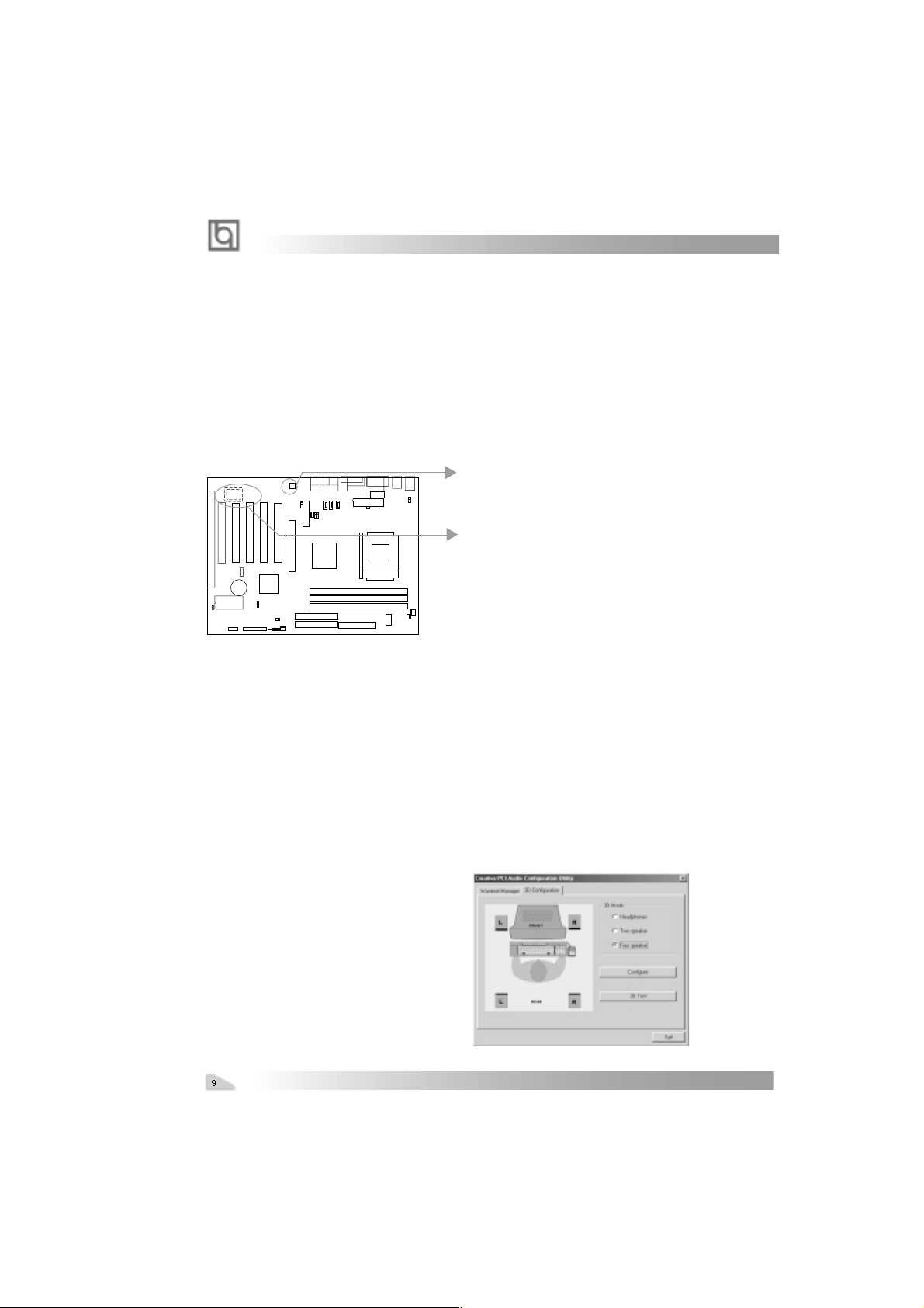
Note : After installation of CT5880dirver, you
can select four speaker output function
Manual for KinetiZ 7T
chapter 2
Chapter 2
Chapter 2
Installation Instructions
Installation Instructions
This section covers External Connectors and Jumper Settings. Refer to the mainboard
layout chart for locations of all jumpers, external connectors, slots and I/O ports. Furthermore, this section lists all necessary connector pin assignments for your reference. The
particular state of the jumpers, connectors and ports are illustrated in the following figures.
Before setting the jumpers or inserting these connectors, please pay attention to the directions.
Be sure to unplug the AC power supply before adding or removing expansion
cards or other system peripherals, otherwise your mainboard and expansion
cards might be seriously damaged.
External Connectors
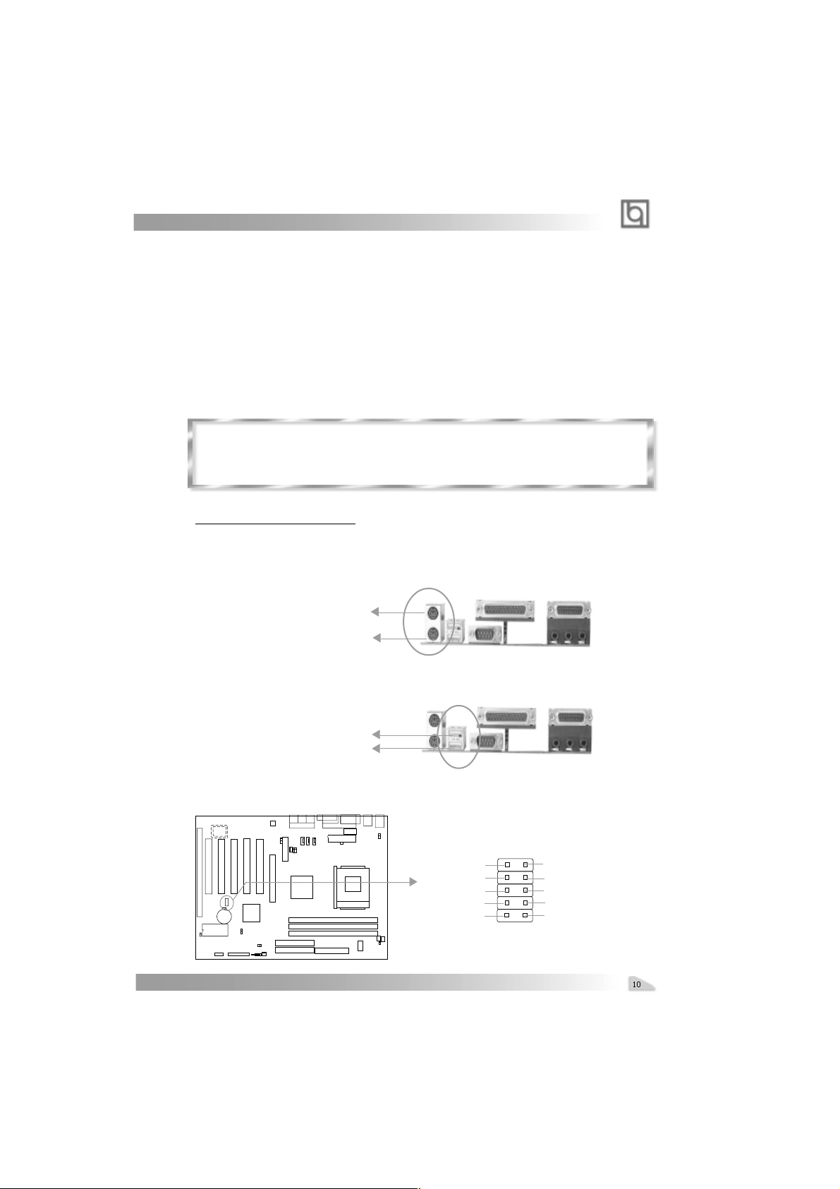
PS/2 Keyboard Connector, PS/2 Mouse Connector
PS/2 keyboard connector is for the usage of PS/2 keyboard. If using a standard AT size
keyboard, an adapter should be used to fit this connector. PS/2 mouse connector is for the
usage of PS/2 mouse.
PS/2 Mouse Connector
PS/2 Keyboard Connector
USB1, USB2
Two USB ports are available for connecting USB devices.
USB1
USB2
USB3, USB4
Two USB ports are not available on the back panel. Therefore, we provide a 10-pin ribbon
cable with bracket to connect Built-in on-board USB header. ( manufacturing option)
+5v
T1T1+
GND
GND
Manual for KinetiZ 7T
GND
GND
T0+
T0+5v
Installation Instruction
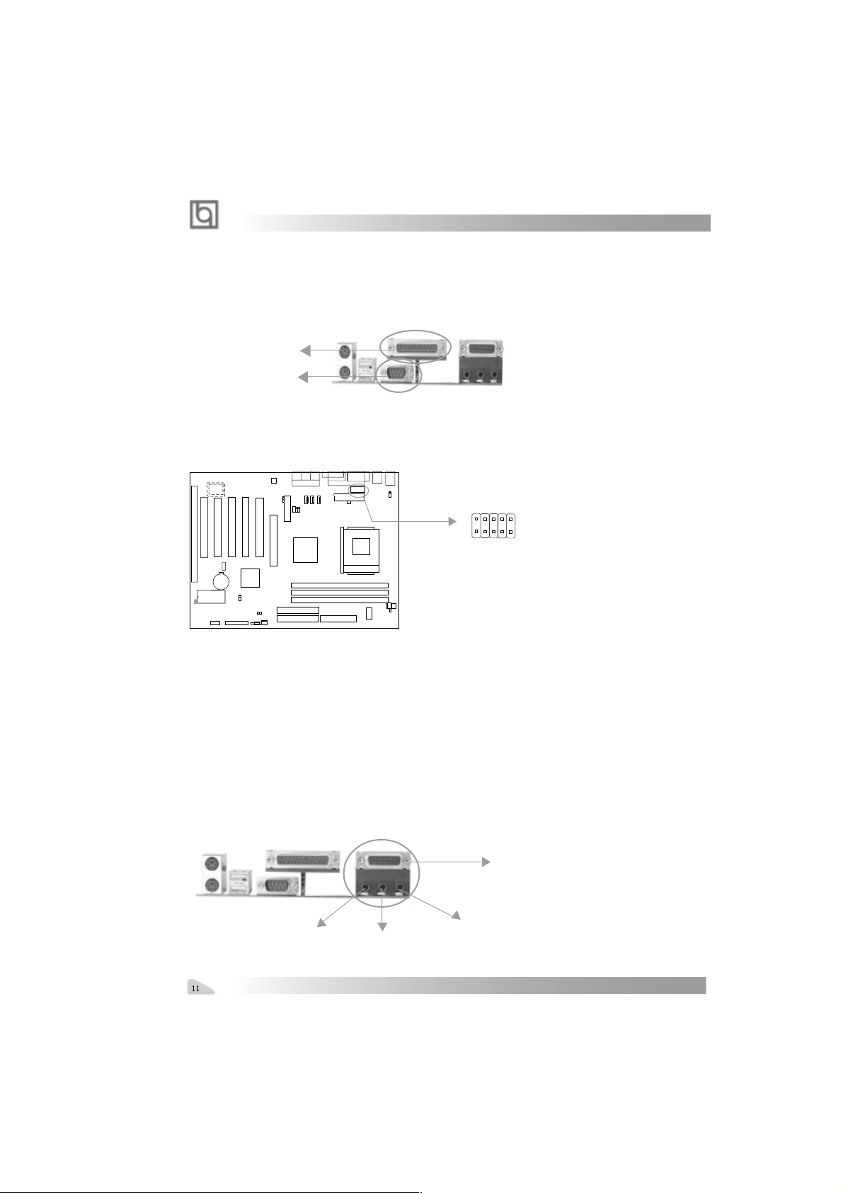
Parallel Port Connector and Serial Port Connector (UART1)
The parallel port connector can be connected to a parallel device such as a printer, while
the serial port connector can be connected to a serial port device such as a serial port
mouse. You can enable/disable them and choose the IRQ or I/O address in “Integrated
Peripherals” from AW ARD BIOS SETUP .
Parallel Port
UART1
UART2
The serial port UART2 is not available on the back panel. Therefore, we provide a 9-pin
ribbon cable with bracket for UART2 port. (manufacturing option)
1
UART2
Line-in jack(or Rear out jack), Microphone-in jack, Speaker-out jack
and
MIDI/Joystick connector
The Line-in jack can be connected to devices such as a cassette or minidisc player for
playback or recording. The Microphone-in jack can be connected to a microphone for voice
input. The Speaker-out jack allows you to connect speakers or headphones for audio
output from the internal amplifier .
Note: if you choose four speaker output in CT5880 configuration, the Rear out
jack replaces Line-in jack to connects powered speakers for audio output.
The MIDI/Joystick connector allows you to connect a game joystick or a MIDI device.
MIDI/Joystick
Speaker out
Line in(or Rear out ) jact
Manual for KinetiZ 7T
Microphone in
chapter 2
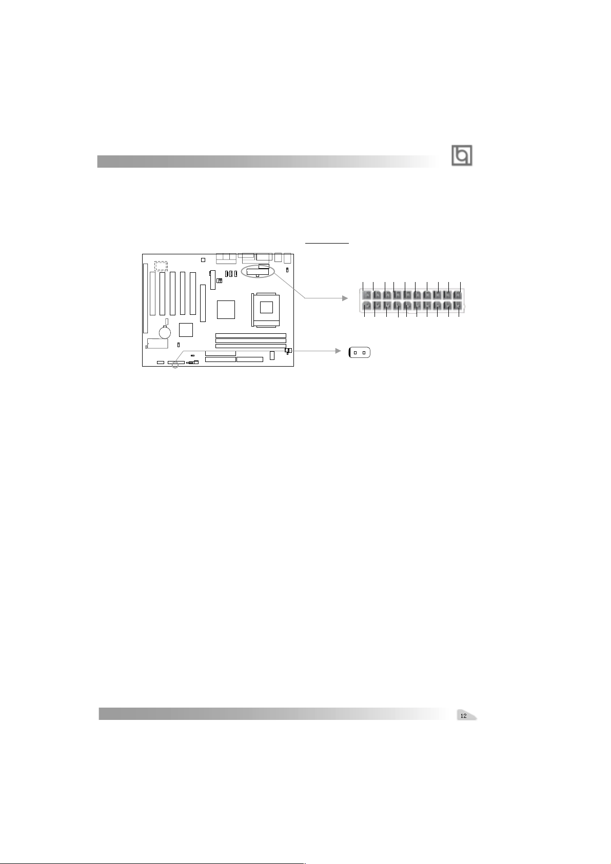
ATX Power Supply Connector & Power Switch (POWER SW)
Be sure to connect the power supply plug to this connector in its proper orientation. The
power switch (POWER SW) should be connected to a momentary switch (power button).
When powering up your system, first turn on the mechanical switch of the power supply (if
one is provided), then push once the power button. When powering off the system, you
needn’t turn off the mechanical switch, just
Push once* the power button.
ATX Power Supply Connector
3.3V 3.3V GND 5V GND 5V GND PS-OK 5VSB 12V
1
3.3V -12V GND PSON GND GND GND -5V 5V 5V
POWER
SW
Note: * If you change “soft-off by PWR-BTTN” from default “Instant-off” to “Delay
4 Secs” in the “POWER MANAGEMENT SETUP” section of the BIOS, the power
button should be pressed for more than 4 seconds before the system powers
down.
Hard Disk LED Connector (HD LED)
The connector connects to the case’s IDE indicator LED indicating the activity status of IDE
hard disk. The connector has an orientation. If one way doesn’t work, try the other way.
20
Reset Switch (RESET)
The connector connects to the case’s reset switch. Press the switch once, the system
resets.
Speaker Connector (SPEAKER)
The connector can be connected to the speaker on the case.
ACPI LED Connector (ACPI_LED)(Reserved)
The ACPI LED is double-color lights with three pins. Pin1&Pin2 drive different color lights. If
Pin1 drives the yellow light , Pin2 drives the green light, the following status will come out.
When the system is in power up status, the LED is green on. When the system is in suspend
status, the LED is green blink. When the system is in suspend to RAM status, the LED is
orange on. When the system is in soft-off status, the LED is off.
GREEN LED Connector (GREEN_LED)
The GREEN LED has five status. When the system is in three status (including power up,
suspend, soft-off), the LED is off. When the system is in suspend to RAM status, the LED
is on. When the system is in APM(advanced power management), the LED is on.
Hardware Green Connector (SLEEP)
Push once the switch connected to this header, the system enters suspend mode.
Manual for KinetiZ 7T
 Loading...