

Page 1

WALL MOUNT
INSTALLATION & USER
INSTRUCTIONS
Page 2

Qasair Rangehoods Installation Instructions2
Page 3

Important Information
Instructions for Models
H Series & PYR
Instructions for Models
3F / SEA / SMF / CM / STA / STF / IN
Instructions for Models
BRH / LAM / BAR / MAR / MAJ / FAS
4
6
10
28
Remote Switching Specications
Ducting Pieces
Installation Ideas
Operation Details, Rangehood Cleaning, Filter Cleaning
Appliance Guarantee
Guarantee Exclusions
Standard Warranty / Extended Warranty
39
42
54
59
60
61
62
Qasair Rangehoods Installation Instructions
3
Page 4

IMPORTANT INFORMATION
The installation of QASAIR Rangehoods must comply with the information in this booklet. QASAIR Rangehoods are
designed and made to work efciently over all domestic cookware available on the Australian market.
Clearance from cooktop to Rangehood
For electric hot plate cooktops
As there are no regulations for Rangehoods over an electric hot plate, please follow the manufacturers Instructions /
Recommendations.
For Induction cooktops
Induction cooktops may present problems with condensation on lters of Rangehoods.
All Qasair Rangehoods installed above an induction cooktop must be installed no less than 750mm between the
induction cooktop and the Rangehood, with the exception of the Eastmore (EAS) Rangehood which can be installed
no less than 600mm. Undermount (NDCH) and Conley (CON) Rangehoods are not suitable for induction cooktops.
For gas cooktops
All Qasair Rangehood installations over a gas appliance must comply with (AS/NZS 5601.1).
The Regulations for the installation of Gas Appliances (AS/NZS 5601.1) states that the clearance between the
highest part of the burner of a gas cooking appliance and a Rangehood be no less than 600mm. If the gas
appliance is designed for use without a cooking vessel like an indoor barbecue or open ame grill, then the
clearance from the cooking surface to the Rangehood shall be no less than 1200mm.
All Qasair Rangehoods installed above a gas cooktop must be installed no less than 600mm between the highest
part of the burner and the Rangehood.
The recommendation for Qasair Wallmount Rangehoods is that they be installed between 700 to 800mm above the
highest part of the burner. When the Rangehood is installed in a galley or partially enclosed kitchen the Rangehood
can be installed between 900 to 1000mm above the highest part of the burner.
Qasair Island Rangehoods should not be installed any higher than 800mm above the highest part of the burner as
any movement around the bench will result in fumes being drawn out from the catchment area of the Rangehood
with the exception of the Thermidor and Liverpool which for aesthetic reasons is installed ush with the ceiling.
Ducting
1. Every QASAIR Rangehood must be ducted to the outside atmosphere by the use of zinc-alume duct or
non-porous and non-ammable materials. Do not use of any type of exible ducting or plastic PVC piping.
Rangehoods must not be vented into a wall cavity or a ceiling space. Externally ducting the rangehood prevents
a build up of grease, which can be a re risk. Ensure the external outlet vent does not restrict the airow in any
way, as this may result in reduced performance.
2. QASAIR Rangehoods must be ducted in duct work equivalent to the outlet of the rangehood ie: The cross
sectional area of the rangehood outlet and the duct work must be equal. Do not reduce the duct size or have
sharp bends. Enlarge the duct size if the duct is to run 6 metres or longer. Advice from CONDARI is available to
ensure optimum performance. Always use nonammable materials to minimise the risk of re in the duct.
3. Ensure all ducting pieces are correctly tted and sealed with either duct tape or silicone to ensure that fumes
do not escape into the ceiling space and seep into living areas through vents or light ttings.
Qasair Rangehoods Installation Instructions4
Page 5

Other Important Information
1. Always adequately ventilate the room when the rangehood is in use at the same time as appliances
burning gas or other fuels.
2. WARNING: Incorrect venting will result in additional noise and a reduction in efciency. Exhaust air must not be
discharged into any chimney or ue, which may carry combustible products from other sources.
a) Do not discharge the air-ow from the rangehood into a ue used for exhausting fumes
from burning gas or fuel;
b) For cleaning purposes please refer to page 59 of installation instructions for stainless steel;
c) If cleaning is not carried out in accordance with the instructions as listed on page 59, there may be an
increased risk of re;
d) Some parts of the rangehood may become hot when cooking;
e) This appliance is not intended for use by persons (including children) with reduced physical, sensory or
mental capabilities, or lack of experience and knowledge, unless they have been given supervision
or instruction concerning use of the appliance by a person responsible for their safety.
3. The installation and tting of the rangehood should be done in such a way that will allow the unit to be removed
if service is required. Additional costs incurred in the removal of wall tiles, damage to walls or bench tops are not
covered by warranty.
4. To reduce the risk of xing screws coming in contact with live parts, do not drill or screw into the rangehood.
Live wires are encapsulated where possible to prevent user contact. If necessary drill from the inside out and
only through single sheet material.
5. NOTE: CONDARI recommend an air movement of between 1000 to 1400 cubic metres per hour over an indoor
barbecue, depending on the length of the duct run. Ensure a twin motor unit is installed over indoor barbecues
for optimum results. Barbecues should be positioned under the centre of the hood where the fans are mounted
and not near the outer edges where leakage may occur.
6. The lights in the rangehoods are LED and come with a night light except for D400L-1 and SEN400L-1.
7. If the supply cord is damaged, an authorised service centre or licensed electrician must replace it.
8. Do not ambé under the rangehood.
9. QASAIR domestic rangehoods must not to be used over barbecues approved for outdoor use only,
CONDARI make a range of hoods specically for outdoor barbecues in alfresco areas under the CONDOR
name.
10. CONDARI can manufacture rangehoods to be used over commercial cookers in domestic applications.
12. NOTE: Ensure all requirements are met with gas and electrical regulations and or state authorities.
Qasair Rangehoods Installation Instructions
5
Page 6
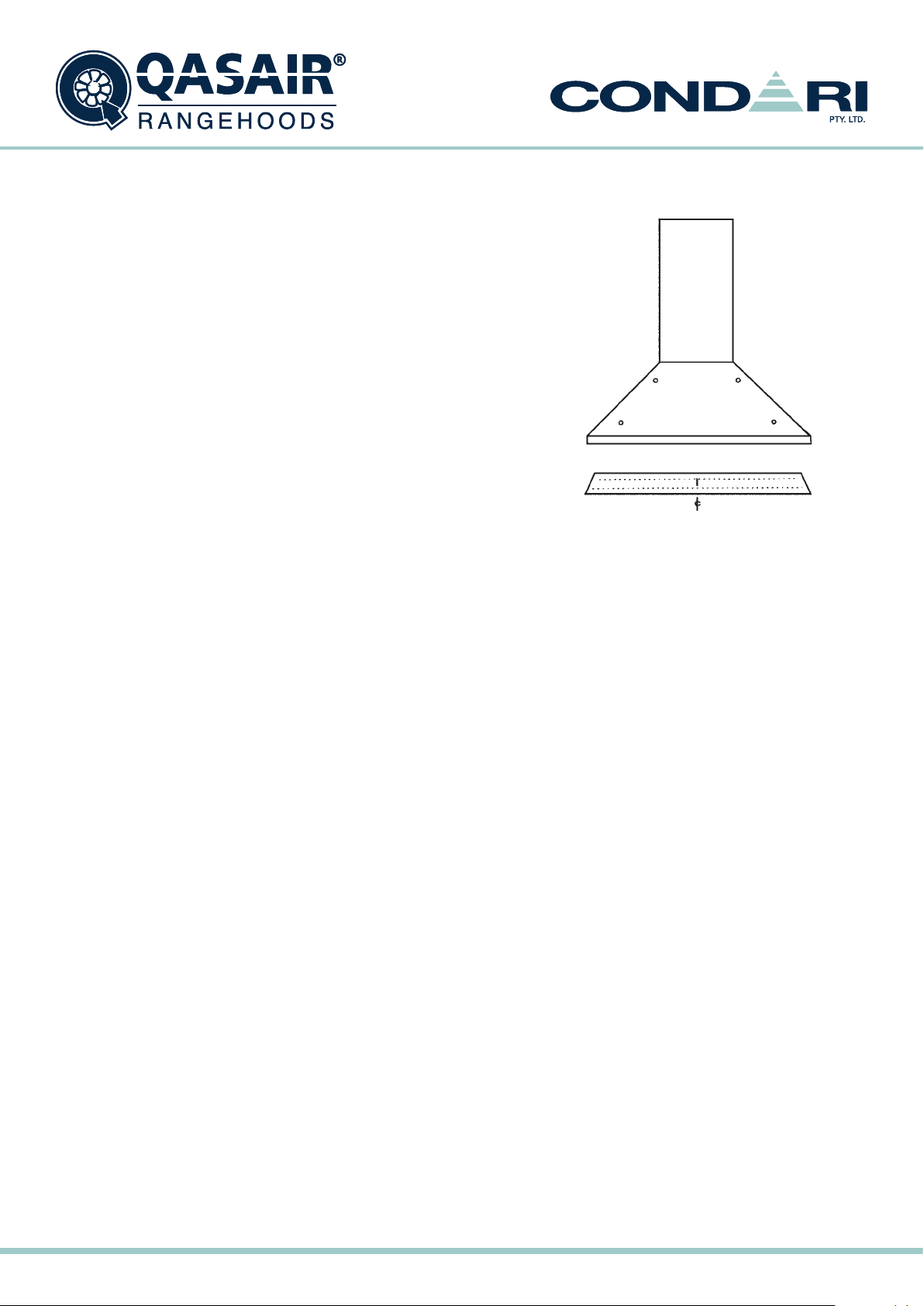
INSTALLATION INSTRUCTIONS
• H SERIES
• PYR
Installation must be carried out by the procedure outlined.
Failure to do so may void the guarantee.
Electrical: Wiring to the appliance must comply with State and local Regulations.
Connection to be carried out by a registered electrician.
Recommended xing points
MOUNTING BRACKET
• Use vertically punched slot for centre line
• Before cutting any holes check ceiling space for structural beams. It may be possible at this point to relocate the
hood position.
The fixing points are prepunched holes in the back of the hood and it may be necessary to drill through the back
of the hood into the wall stud.
1. Remove canopy and flue from boxes and check you have correct model and flue.
2. Locate centre point of cooktop.
3. Use level or plumb line to mark centre up to ceiling.
4. Mark level line for base of canopy 700-800mm above bench 750mm desirable.
5. Check roof space above for wires and obstructions as now is the time to decide on any changes to location due
to immovable obstructions.
6. Mark flue size on ceiling and cut neat exact hole to pass flue through.
7. For rear ducted models cut hole in wall for vent to pass through.
8. Fix mounting bracket to wall at desired height.
9. Remove fan(s) from canopy by removing side fixing bolts and disconnecting electrical plug at flexible connector.
10. Locate solid fixing points on wall and drill holes in rear of canopy to suit. If no solid fixing is available then now is
the time to install fixing points. Four points are recommended with one on each side at top and one on each side
at bottom.
11. Drill hole in rear of unit to pass power connection through where available on wall.
12. Check flue slides through hole in ceiling.
13. Place canopy flat on floor and fit stainless flue over spigot pushing all the way down for a neat fit. Drill hole in
rear of flue and fix to canopy with pop rivet or screw.
14. Carefully lift canopy into position, guiding flue through ceiling and feeding power cable through hole in rear of
canopy. Make sure canopy is sitting correctly on mounting bracket then fix to wall through fixing holes with solid
screws. (You may need to place a packer behind canopy if wall is bowed to make the canopy sit correctly).
15. Complete electrical connection to 10 AMP junction box to local electrical authority regulations ensuring power is
turned off during work.
16. Fit ducting to outside or exterior wall vent for rear ducted models. (Seal rear vents onto rear of hood with
silicone). A plumber should seal roof penetration with appropriate flashing. All joins in ducting need to be sealed
with duct tape or silicone and only use approved ducting of the correct size for your canopy.
17. Fit motor(s) back into canopy with fixing bolts and plug electrical connector in.
18. Test run hood.
Qasair Rangehoods Installation Instructions6
Page 7
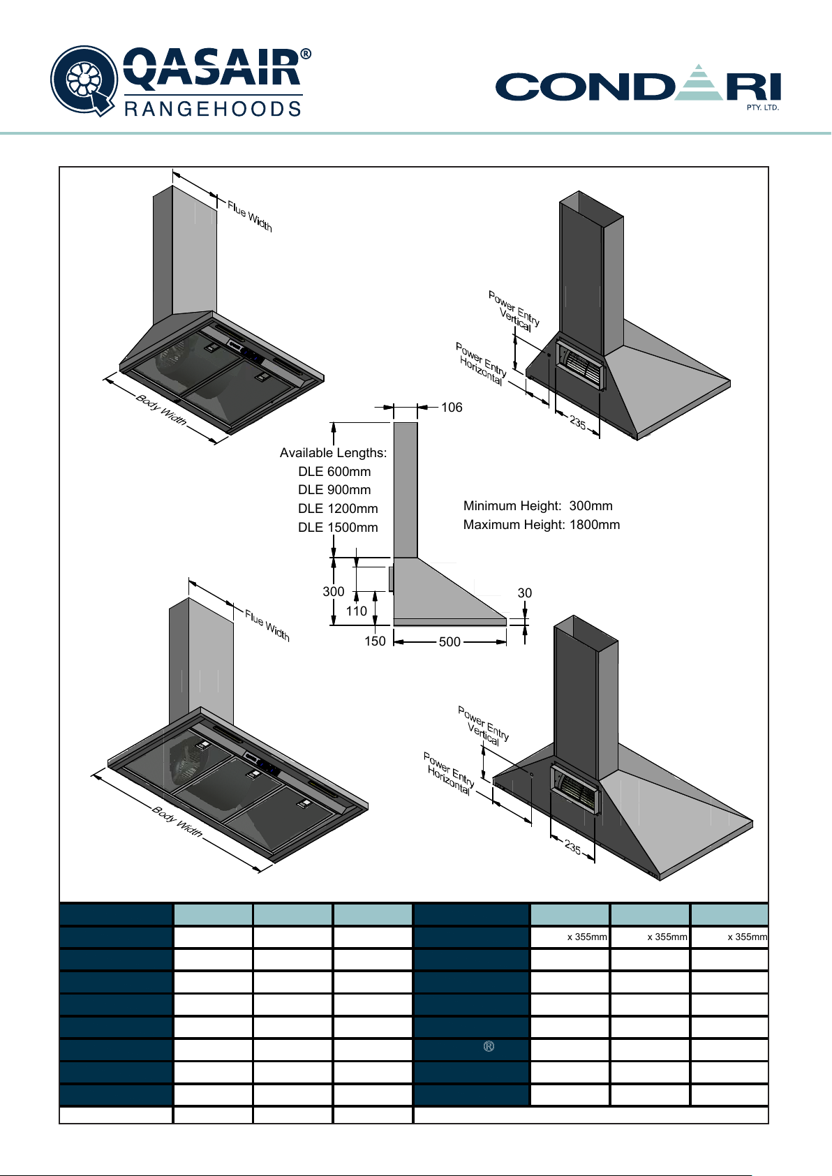
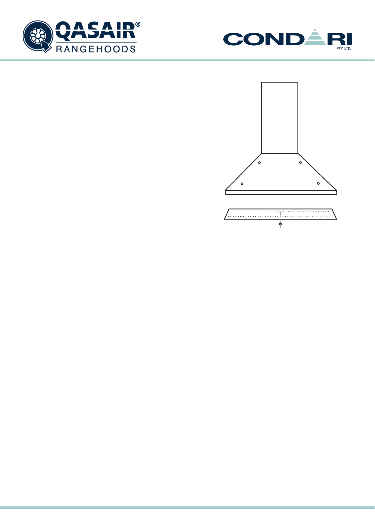
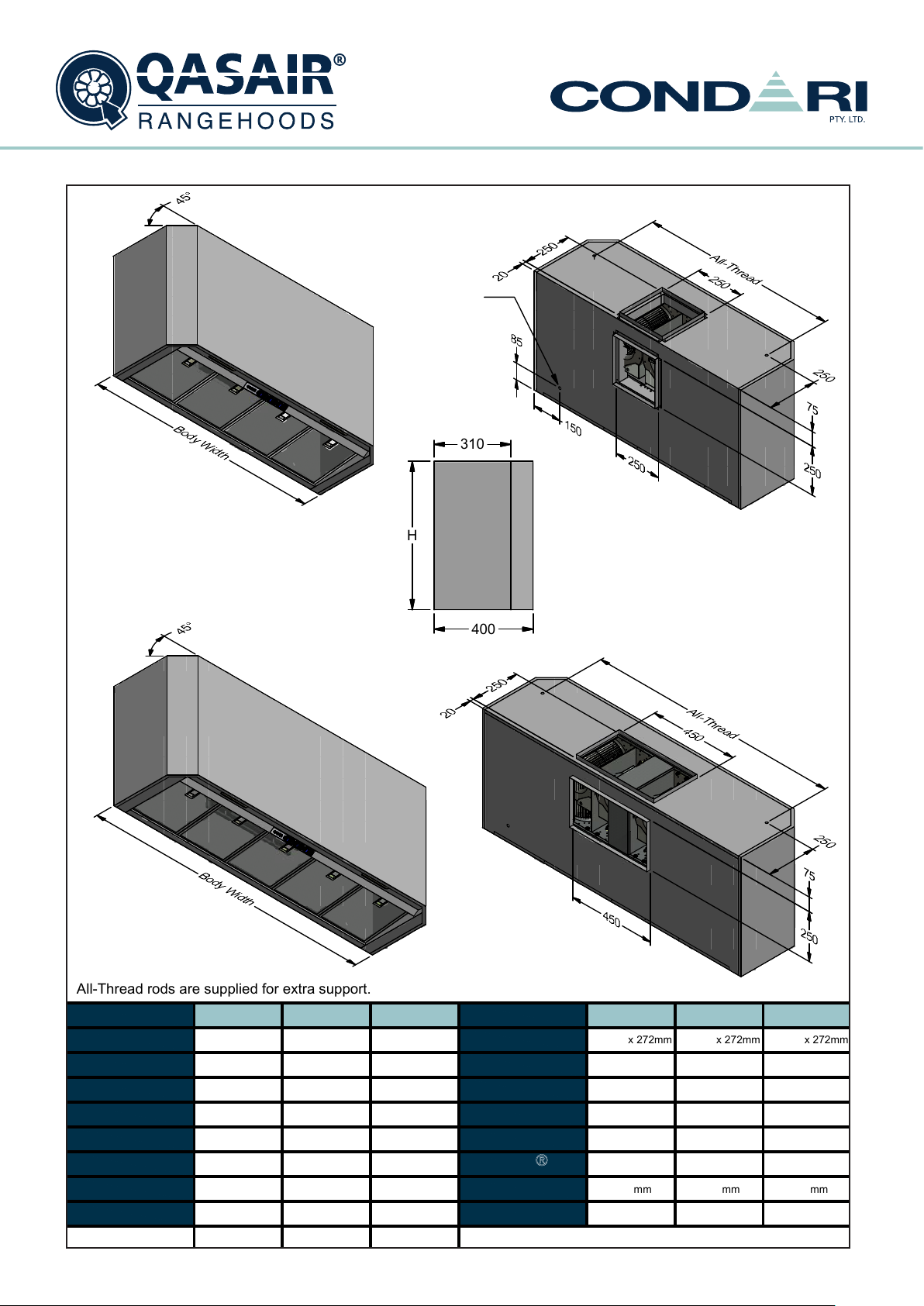
Heritage
Technical Specification Sheet
H
Wall Mounted
Condari Pty Ltd.
Version: C 20/01/2015F
Page 1 of 2
m
m
HERITAGE - H
Available Lengths
DLE 600mm
DLE 900mm
DLE 1200m
DLE 1500m
300
110
106
:
m
m
Minimum Height:
Maximum Height: 1800m
3
0
300mm
m
150
Model 600HL-1
Body Width
Motor Box /
Flue Width
Motor Qty
LED Light
Nightlight
Light Qty
Light Centres
Filter Qty
600HL-1
600mm
240mm
1
Cool
YES
2
310mm
2
700HL-1
700mm
240mm
Cool
310mm
2
900mm
240mm
11
Cool
YESYES
22
510mm
3
500
Model900HL-1
Filter Size
Conversion
Top/Back Back/Top
Electrical Connection
Power Entry Vertical
Power Entry Horizontal
PowderKote
Available
Outlet Spacing
Corner Type
x 355mm
272mm
NO
Junction BoxNOJunction Box
150mm
125mm
YES
N/A
Square Square
700HL-1
x 355mm
290mm
130mm
135mm 210mm
YES
N/A N/A
272mm
900HL-1
355
x
NO
Junction Box
150mm
YES
Square
Qasair Rangehoods Installation Instructions
7
Page 8
Heritage
Technical Specification Sheet
H
Wall Mounted
m
m
Version: C 20/01/2015F
HERITAGE - H
Available Lengths
DLE-2 600mm
DLE-2 900mm
DLE-2 1200m
DLE-2 1500m
110
375
150
:
m
m
Minimum Height:
Maximum Height: 1875m
3
0
375mm
m
Model
Body Width
Motor Box /
Flue Width
Motor Qty
LED Light
Nightlight
Light Qty
Light Centres
Filter Qty
1000HL-2
1000mm
370mm
2
Cool
YES
510mm
3
1200HL-2
370mm
2
Cool
YES
22
648mm
4
150
1500mm1200mm
370mm
2
Cool
YES
2
816mm
5
500
Model1500HL-2
Filter Size
Conversion
Top/Back Back/Top
Electrical Connection
Power Entry Vertical
Power Entry Horizontal
PowderKote
Available
Outlet Spacing
Corner Type
Condari Pty Ltd.
1000HL-2
290mm
x
NO
Junction Box
130mm
150mm
YES
75mm
Square
355mm
1200HL-2
x 355mm
272mm
NO
Junction Box
190mm
250mm
YES
100mm
Square
1500HL-2
x 355
272mm
NO
Junction Box
215mm
375mm
YES
100mm
Square
Page 2 of 2
Qasair Rangehoods Installation Instructions8
Page 9
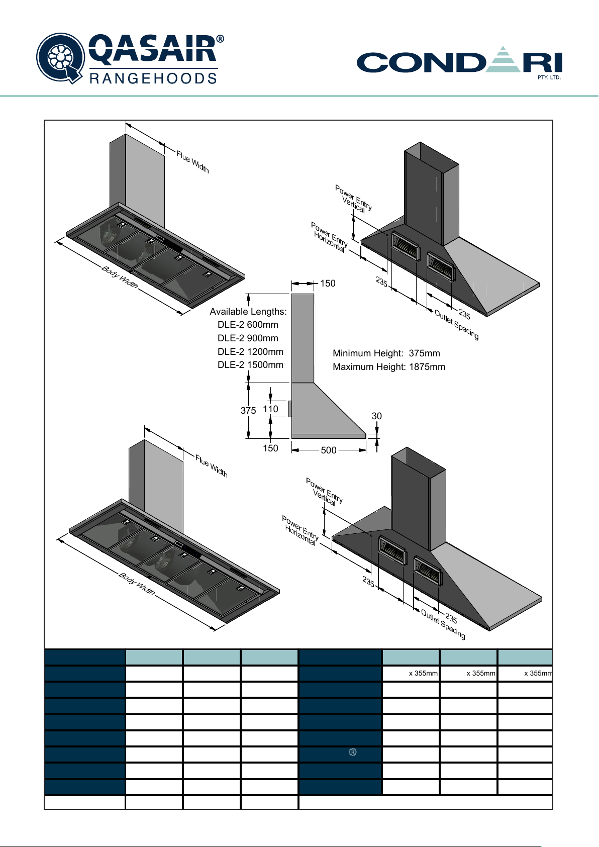
Pyramid
Technical Specification Sheet
PYR
Wall Mounted
Conversion
Top/Back Back/Top
Filter Size
Model
Electrical Connection
Minimum Height
(H =)
Maximum Height
(H =)
PowderKote
Available
All-thread
Fixing Centres
Page 1 of 1
Corner Type
N/A
Filter Qty
3
Motor Qty
Light Qty
Light Centres
Motor Box /
Flue Width
Body Width
Model
Cool
YES
2
PYR 900L-1
1
900mm
270mm
510mm
LED Light
Nightlight
Condari Pty Ltd.
Junction Box
PYR 900L-1
Square
Version: B 20/01/2015F
NO
N/A
N/A
N/A
272mm
x
355mm
500
380
150
110
3
0
Power Entry
280
Available Lengths
:
DLP 600mm
DLP 900mm
DLP 1200m
m
DLP 1500m
m
2
0
110
500
3
0
230
PYRAMID - PYR
Qasair Rangehoods Installation Instructions
9
Page 10
INSTALLATION INSTRUCTIONS
• 3F
• SEA
• SMF
• CM
• STA / STF
• IN (REMOTE SWITCHED)
Installation must be carried out by the procedure outlined.
Failure to do so may void the guarantee.
Electrical: Wiring to the appliance must comply with State and local Regulations.
Connection to be carried out by a registered electrician.
Recommended xing points
1. Prepare wall by marking level line at desired height above cooktop.
2. Plumb line from centre of cooktop to ceiling and mark flue cut out.
3. Mark level line for base of canopy 700-800mm above bench 750mm desirable.
4. Position mounting bracket on wall and fix with four screws.
5. Cut a neat hole through the ceiling and remove any obstructing timbers.
6. Note: Various offsets are available from your QASAIR dealer to duct around any major structural beams which
cannot be removed. Ask your QASAIR dealer for advice.
7. In the case of back ducted models, cut a hole in the wall at the desired height.
8. Locate solid fixing point in wall to support hood. If there is no solid fixing point it will have to be placed in the wall
before proceeding. QASAIR recommend at least four (4) fixing points.
9. Drill holes in back of unit at suitable fixing points.
10. Drill 20mm hole in the rear of unit for 240 volt power cable as close as possible to junction box or use hole below
the junction box.
11. Attach flue (if applicable), then carefully lift into position on level line. Ensure flue is pushed into position and
electrical cable is fed into rear of unit.
12. Duct in approved manner to outside atmosphere.
Qasair Rangehoods Installation Instructions10
Page 11
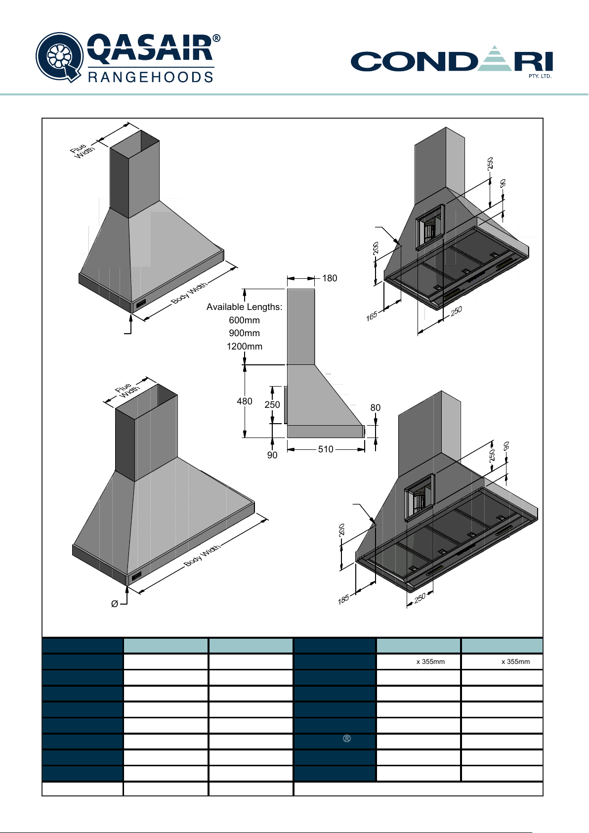
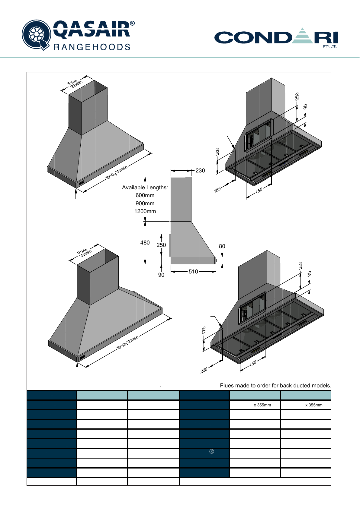
3 Flare
Technical Specification Sheet
3F Wall Mounted
3F 1200L-2
2
3
510mm
YESYES
2
1200mm
400mm
22
300mm
Cool
900mm
3F 900L-2
Cool
Light Centres
Filter Qty
Nightlight
Light Qty
LED Light
Motor Qty
Model
Body Width
Maximum Height
(H =)
Corner Type
648mm
Condari Pty Ltd.
4
All-thread
Fixing Centres
PowderKote
Available
Filter Size
Conversion
Top/Back Back/Top
Page 1 of 2
Motor Box /
Flue Width
Minimum Height
(H =)
Model
Electrical Connection
480mm
NO
3F 900L-2
272mm
x
355mm
Version: C 20/01/2015F
YES
1680mm
Junction Box Junction Box
NO
1680mm
YES
480mm
Round
N/A
Round
N/A
272mm
x
355mm
3F 1200L-2
Power Entry
Power Entry
A Transition is supplied to suit standard DL2 ducting.
Flues made to order for back ducted models.
Ø15mm Radius
Ø15mm Radius
Ø
510
8
0
9
0
250
480
180
Available Lengths
:
600mm
900mm
1200m
m
3 FLARE - 3F
Qasair Rangehoods Installation Instructions
11
Page 12
3 Flare
Technical Specification Sheet
3F Wall Mounted
Filter Qty
Nightlight
Light Qty
Light Centres
Motor Qty
LED Light
Motor Box /
Flue Width
Model
Body Width
4
816mm
5
Conversion
Top/Back Back/Top
Condari Pty Ltd.
Maximum Height
(H =)
All-thread
Fixing Centres
Minimum Height
(H =)
Corner Type
3F 1500L-3 Model
648mm
Electrical Connection
PowderKote
Available
YES
Round
N/A
Version: C 20/01/2015F
Page 2 of 2
N/A
YES
450mm
3
1200mm
3F 1200L-3 3F 1200L-3
NO
Junction Box
272mm
x
355mm
480mm
1680mm 1680mm
3F 1500L-3
Round
Junction Box
Filter Size
3
2
Cool
272mm
x
355mm
NO
500mm
Cool
1500mm
2
YES
480mm
YES
Power Entry
Power Entry
Ø15mm
Radius
Ø15mm Radius
A Transition is supplied to suit standard DL3 ducting
.
Flues mad
e t
o order for bac
k ducte
d models.
510
8
0
9
0
250
480
Available Lengths
:
600mm
900mm
1200m
m
230
3 FLARE - 3F
Qasair Rangehoods Installation Instructions12
Page 13
Motor Box /
Flue Width
Condari Pty Ltd. Page 1 of 2
Version: C 20/01/2015F
Body Width
Model
Motor Qty
Light Centres
Light Qty
Nightlight
LED Light
Filter Qty
Model
Filter Size
Conversion
Top/Back Back/Top
Electrical Connection
Minimum Height
(H =)
Maximum Height
(H =)
PowderKote
Available
All-thread
Fixing Centres
Corner Type
SEA 600L-1 SEA 900L-2SEA 900L-1SEA 600L-1SEA 900L-2SEA 900L-1
600mm
Centre
2
N/A
1
Cool
YES
1
272mm
x
272mm
NO
Junction Box
400mm
1450mm
YES
400mm
Square
900mm
N/A
1
Cool
YES
2
510mm
3
900mm
N/A
2
Cool
YES
2
510mm
3
272mm
x
272mm
NO
Junction Box
400mm
1450mm
YES
700mm
Square
272mm
x
272mm
NO
Junction Box
400mm
1450mm
YES
700mm
Square
Senator
Technical Specification Sheet
SEA
Wall Mounted
Power entry location
is the same for all
Senator models.
H
400
310
All-Threa
d rod
s are supplie
d for extra support
.
SENATOR - SEA
Qasair Rangehoods Installation Instructions
13
Page 14
m
m
Version: C 20/01/2015F
Senator
Technical Specification Sheet
SEA
Wall Mounted
All
SENATOR - SEA
Power entry location
is the same for all
Senator models.
310
H
400
-Thread rod
Model
Body Width
Motor Box /
Flue Width
Motor Qty
LED Light
Nightlight
Light Qty
Light Centres
Filter Qty
s are supplie
SEA 1200L-2
1200mm
N/A
Cool
YES
648mm
d for extra support
SEA 1500L-2 SEA 1500L-3
1500mm
2
2
816mm
4
.
1500mm
N/A
2
Cool
YES YES
5
N/A
3
Cool
22
816mm
5
Model
Filter Size
Conversion
Top/Back Back/Top
Electrical Connection
Minimum Height
(H =)
Maximum Height
(H =)
PowderKote
Available
All-thread
Fixing Centres
Corner Type
Condari Pty Ltd.
SEA 1200L-2
x 272mm
272mm
NO
Junction Box
400mm
1450mm
YES
1000
Square
m
m
SEA 1500L-2
x 272mm
272mm
NO NO
Junction Box
400mm
1450mm
YES
m
m
1300
Square
SEA 1500L-3
x 272
272mm
Junction Box
400mm
1450mm
YES
m
1300
Square
Page 2 of 2
m
Qasair Rangehoods Installation Instructions14
Page 15
m
m
Maitland
Technical Specification Sheet
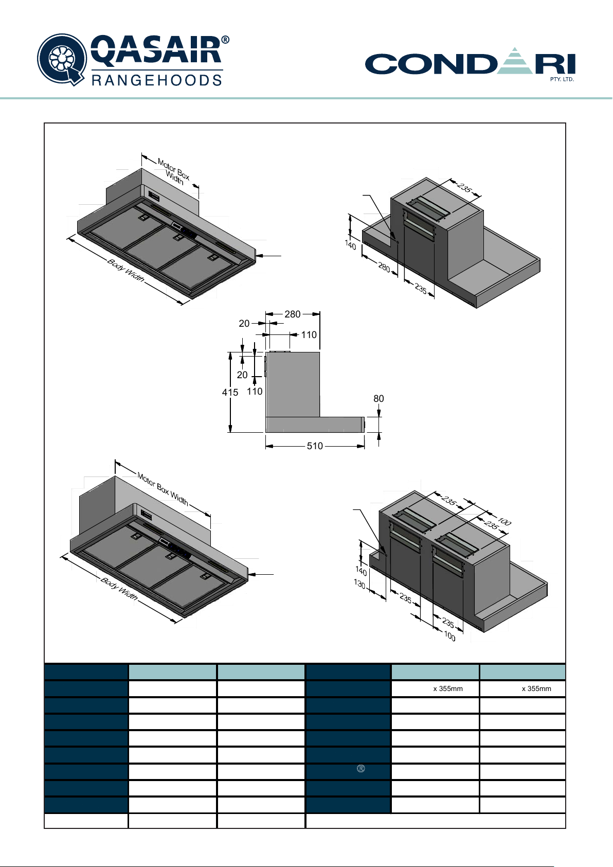
SMF
Wall Mounted
MAITLAND - SMF
450
Power entry location
is the same for all
SMF models.
Ø15mm Radius
280
110
2
0
2
0
110
150
510
Model
Body Width
Motor Box /
Flue Width
Motor Qty
LED Light
Nightlight
Light Qty
Light Centres
Filter Qty
SMF 600L-1 SMF 900L-2SMF 900L-1SMF 600L-1SMF 900L-2SMF 900L-1
600mm
450mm
1
Cool
YES
2
310mm
2
900mm
750mm
510mm
Qasair Rangehoods Installation Instructions
1
Cool
YES
2
3
900mm
750mm
2
Cool
YES
2
510mm
3
Ø15mm
Radius
Model
Filter Size
Conversion
Top/Back Back/Top
Electrical Connection
Minimum Height
(H =)
Maximum Height
(H =)
PowderKote
Available
All-thread
Fixing Centres
Corner Type
Condari Pty Ltd. Page 1 of 4
x 355mm
272mm
YES
Junction Box
N/A
N/A
YES
N/A
Round
Version: C 20/01/2015F
272mm
Junction Box
x 355mm
YES
N/A
N/A
YES
N/A
Round
x 355
272mm
YES
Junction Box
N/A
N/A
YES
N/A
Round
15
Page 16
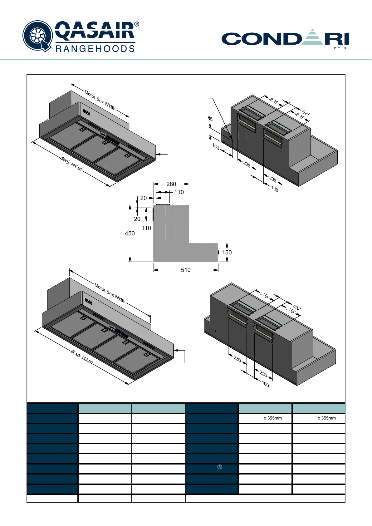
Maitland
Technical Specification Sheet
SMF
Wall Mounted
Version: C 20/01/2015F
Condari Pty Ltd.
Page 2 of 4
MAITLAND - SMF
450
Power entry location
is the same for all
2
0
2
0
110
SMF models.
Ø15mm Radius
280
110
150
Model
Body Width
Motor Box /
Flue Width
Motor Qty
LED Light
Nightlight
Light Qty
Light Centres
Filter Qty
SMF 1000L-2
1000mm
850mm
2
Cool
YES
2
510mm
3
SMF 1200L-2
1200mm
1050mm
2
YES
2
648mm
4
510
Ø15mm
Radius
Model
Filter Size
Conversion
Top/Back Back/Top
Electrical Connection
Minimum Height
(H =)
Maximum Height
(H =)
PowderKote
Available
All-thread
Fixing Centres
Corner Type
SMF 1000L-2
x 355mm
290mm
YES
Junction Box
N/ACool
N/A
YES
N/A
Round
SMF 1200L-2
x 355mm
272mm
YES
Junction Box
N/A
N/A
YES
N/A
Round
Qasair Rangehoods Installation Instructions16
Page 17
Minimum Height
(H =)
Filter Size
Model
Conversion
Top/Back Back/Top
N/A
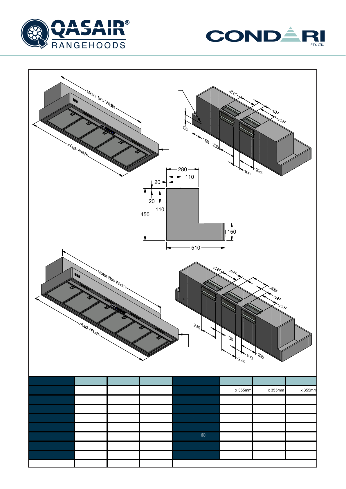
SMF 1500L-3
Electrical Connection
Page 3 of 4
Body Width
Motor Box /
Flue Width
Motor Qty
Model
Nightlight
Filter Qty
Light Qty
Version: C 20/01/2015F
Light Centres
Maximum Height
(H =)
Corner Type
Condari Pty Ltd.
1350mm
1500mm
SMF 1500L-2
5
LED Light
816mm
YES
N/A
YES
Junction Box
272mm
x 355mm
SMF 1500L-2
N/A
SMF 1800L-3
YES
YESYES
2
N/A
272mm
x 355mm
290mm
x 355mm
All-thread
Fixing Centres
PowderKote
Available
SMF 1800L-3
1800mm
1650mm
4
3
1500mm
1350mm
422mm
6
YES
5
Cool Cool
3
2
SMF 1500L-3
N/A
Round
YES
Junction BoxJunction Box
YES
N/A
Round
N/A
YES
N/A
Round
N/A
816mm
2
Cool
Maitland
Technical Specification Sheet
SMF
Wall Mounted
280
110
2
0
450
2
0
110
150
510
Power entry location
is the same for all
SMF models.
Ø15mm Radius
Ø15mm
Radius
MAITLAND - SMF
Qasair Rangehoods Installation Instructions
17
Page 18
Wall Mounted
Maitland
Technical Specification Sheet
SMF
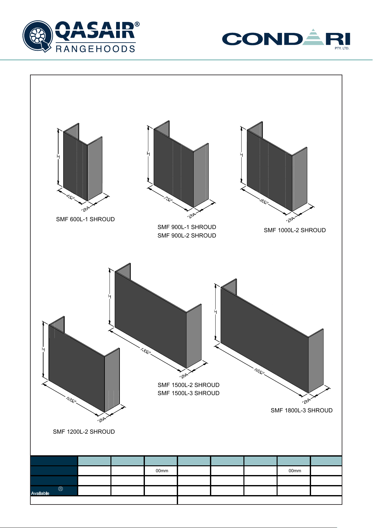
SMF 600L-1
SHROUD
YES YES
SMF 900L-2
SHROUD
1450mm1450mm
SMF 1500L-3
SHROUD
300mm
Version: C 20/01/2015F
Page 4 of 4
SMF 1200L-2
SHROUD
Condari Pty Ltd.
Model
3
00m
m
3
00m
m
1450mm
YES
Minimum Height
(H =)
Maximum Height
(H =)
YES
Powderkote
Available
300mm
1450mm
SMF 900L-1
SHROUD
YES
SMF 1000L-2
SHROUD
YES
1450mm
300mm
YES
1450mm
300mm
YES
300mm
1450mm1450mm
300mm
SMF 1500L-2
SHROUD
SMF 1800L-3
SHROUD
SMF 600L-
1 SHROU
D
SMF 900L-
1 SHROU
D
SMF 900L-
2 SHROU
D
SMF 1000L-2 SHROU
D
SMF 1200L-2 SHROU
D
SMF 1500L-2 SHROU
D
SMF 1500L-3 SHROU
D
SMF 1800L-3 SHROU
D
MAITLAND - SMF
Qasair Rangehoods Installation Instructions18
Page 19
Compact
Technical Specification Sheet
CM
Wall Mounted
COMPACT - CM
415
Power Entry
Ø15mm
Radius
280
2
0
110
2
0
110
8
0
Model
Body Width
Motor Box /
Flue Width
Motor Qty
LED Light
Nightlight
Light Qty
Light Centres
Filter Qty
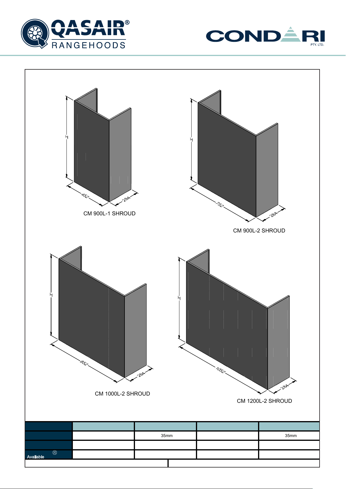
CM 900L-1
900mm
450mm
Cool
2
510mm
3
CM 900L-2
900mm
750mm
21
Cool
YESYES
2
510mm
3
Power Entry
Ø15mm
Radius
510
Model
Filter Size
Conversion
Top/Back Back/Top
Electrical Connection
Minimum Height
(H =)
Maximum Height
(H =)
PowderKote
Available
All-thread
Fixing Centres
Corner Type
Condari Pty Ltd.
CM 900L-1
x 355mm
272mm
YES
Junction Box Junction Box
N/A
N/A
YES
N/A
Round
Version: C 20/01/2015F
272mm
Page 1 of 3
CM 900L-2
355mm
x
YES
N/A
N/A
YES
N/A
Round
Qasair Rangehoods Installation Instructions
19
Page 20
Compact
Technical Specification Sheet
CM
Wall Mounted
Version: C 20/01/2015F
COMPACT - CM
415
Power Entry
Ø15mm
Radius
280
2
0
110
2
0
110
8
0
Model
Body Width
Motor Box /
Flue Width
Motor Qty
LED Light
Nightlight
Light Qty
Light Centres
Filter Qty
510
Power Entry
Ø15mm
Radius
CM 1000L-2 CM 1000L-2
1000mm
850mm
2
Cool
YES
2
510mm
3
CM 1200L-2 Model
1200mm
1050mm
2
Cool
YES
2
648mm
4
Filter Size
Conversion
Top/Back Back/Top
Electrical Connection
Minimum Height
(H =)
Maximum Height
(H =)
PowderKote
Available
All-thread
Fixing Centres
Corner Type
Condari Pty Ltd.
355mm
x
290mm
YES
Junction Box
N/A
N/A N/A
YES
N/A
Round
CM 1200L-2
272mm
Junction Box
Round
Page 2 of 3
x
YES
N/A
YES
N/A
355mm
Qasair Rangehoods Installation Instructions20
Page 21
Wall Mounted
Compact
Technical Specification Sheet
CM
Version: C 20/01/2015F
A
v
COMPACT - CM
C
M 900L-
1 SHROU
D
C
M 900L-
2 SHROU
D
C
M 1000L-2 SHROU
Model
Minimum Height
(H =)
Maximum Height
(H =)
Powderkote
ailable
Qasair Rangehoods Installation Instructions
CM 900L-1 SHROUD
1450mm
YES
D
CM 900L-2 SHROUD
35m
m
3
1450mm
YES
Condari Pty Ltd.
CM 1000L-2 SHROUD
335mm335mm
1450mm
YES
C
M 1200L-2 SHROU
CM 1200L-2 SHROUD
Page 3 of 3
D
35m
3
1450mm
YES
m
21
Page 22

Wall Mounted
Statesman
Technical Specification Sheet
STA
STATESMAN - STA
15m
Radiu
280
110
2
2
0
110
H
0
8
0
510
m
s
STA 900L-1 shown
without shroud.
Shrou
d
Model
Body Width
Motor Box /
Flue Width
Motor Qty
LED Light
Nightlight
Light Qty
Light Centres
Filter Qty
Power Entry
STA 900L-1
900mm
403mm
1
Cool
YES
2
510mm
3
Shroud
Model
Filter Size
Conversion
Top/Back Back/Top
Electrical Connection
Minimum Height
(H =)
Maximum Height
(H =)
PowderKote
Available
All-thread
Fixing Centres
Corner Type
Condari Pty Ltd.
STA 900L-1
272mm
YES
Junction Box
415mm
1550mm
YES
Round
Version: E 29/06/2016F
x 355mm
N/A
Page 1 of 3
Qasair Rangehoods Installation Instructions22
Page 23

Statesman
Technical Specification Sheet
STA
Wall Mounted
R
a
STATESMAN - STA
STA 900L-2 shown
without shroud.
380
250
2
0
2
0
250
H
8
0
510
Shrou
d
Shroud
Power Entry
ngehood i
Model
Body Width
Motor Box /
Flue Width
Motor Qty
LED Light
Nightlight
Light Qty
Light Centres
Filter Qty
s manufacture
d a
s top duc
STA 900L-2
900mm
403mm
510mm
2
Cool
YES
2
3
t only.
A
conversio
n kit for bac
Model
Filter Size
Conversion
Top/Back Back/Top
Electrical Connection
Minimum Height
(H =)
Maximum Height
(H =)
PowderKote
Available
All-thread
Fixing Centres
Corner Type
Condari Pty Ltd.
k ducte
d i
s supplied.
Version: E 29/06/2016F
STA 900L-2
x 355mm
272mm
YES
Junction Box
740mm
1550mm
YES
N/A
Round
Page 2 of 3
Qasair Rangehoods Installation Instructions
23
Page 24

Wall Mounted
Statesman
Technical Specification Sheet
STA
R
a
STATESMAN - STA
STA 1200L-2 shown
without shroud.
Shroud
380
250
2
0
2
0
250
H
8
0
510
Shrou
d
Power Entry
ngehood i
Model
Body Width
Motor Box /
Flue Width
Motor Qty
LED Light
Nightlight
Light Qty
Light Centres
Filter Qty
s manufacture
d a
s top duc
STA 1200L-2
1200mm
t only.
403mm
2
Cool
YES
2
648mm
4
A
conversio
n kit for bac
Model
Filter Size
Conversion
Top/Back Back/Top
Electrical Connection
Minimum Height
(H =)
Maximum Height
(H =)
PowderKote
Available
All-thread
Fixing Centres
Corner Type
Condari Pty Ltd.
k ducte
d i
s supplied.
Version: E 29/06/2016F
STA 1200L-2
x 355mm
272mm
YES
Junction Box
740mm
1550mm
YES
N/A
Round
Page 3 of 3
Qasair Rangehoods Installation Instructions24
Page 25

STAFFORD - STF
Stafford
Technical Specification Sheet
STF
Wall Mounted
STF 900L-2 shown
without shroud.
Shroud
Shroud
380
2
0
2
0
250
Power Entry
250
H
510
8
0
Shown with Shroud
STF 1200L-2 shown
without shroud.
Power Entry
Rangehood is manufactured as top ducted only. A conversion kit for back ducted is supplied.
Model
Body Width
Motor Box /
Flue Width
Motor Qty
LED Light
Nightlight
Light Qty
Light Centres
Filter Qty
STF 900L-2
900mm
403mm
2
Cool
YES
22
510mm
3
STF 1200L-2
1200mm
403mm
2
Cool
YES
648mm
4
Model
Filter Size
Conversion
Top/Back Back/Top
Electrical Connection
Minimum Height
(H =)
Maximum Height
(H =)
PowderKote
Available
All-thread
Fixing Centres
Corner Type
Condari Pty Ltd.
STF 900L-2
x 355mm
272mm
YES
Junction Box
740mm
1280mm
N/A
N/A
Square
Version: C 20/01/2015F
Shroud
STF 1200L-2
272mm
YES
Junction Box
740mm
1280mm
Square
Page 1 of 1
x 355mm
N/A
N/A
Qasair Rangehoods Installation Instructions
25
Page 26

Integra
Technical Specification Sheet
IN
Wall Mounted
Version: A 28/11/2014F
INTEGRA - IN
300
Power entry locations
are the same for all
Integra models.
600
110
7
2
0
0
110
2
0
100
Model
Body Width
Motor Box /
Flue Width
Motor Qty
LED Light
Nightlight
Light Qty
Light Centres
Filter Qty
IN 600L-1
600mm
N/A
1
Cool
NO
12
Centre
2
IN 900L-2
900mm
N/A
2
Cool
NO
285mm
3
Model
Filter Size
Conversion
Top/Back Back/Top
Electrical Connection
Minimum Height
(H =)
Maximum Height
(H =)
PowderKote
Available
All-thread
Fixing Centres
Corner Type
Condari Pty Ltd.
IN 600L-1
272mm
YES
Remot
Square
Qasair Rangehoods Installation Instructions26
x 355mm
e Switching
N/A
N/A
N/A
N/A
IN 900L-2
x 355mm
272mm
YES
Remote Switching
N/A
N/A
N/A
N/A
Square
Page 1 of 2
Page 27

Integra
Technical Specification Sheet
IN
Wall Mounted
INTEGRA - IN
Power entry locations
are the same for all
Integra models.
2
0
110
2
0
300
100
110
600
7
0
Model
Body Width
Motor Box /
Flue Width
Motor Qty
LED Light
Nightlight
Light Qty
Light Centres
Filter Qty
IN 1200L-2
1200mm
N/A
2
Cool
NO
2
560mm
4
Qasair Rangehoods Installation Instructions
IN 1200L-3
1200mm
N/A
3
Cool
NO
2
560mm
4
Model
Filter Size
Conversion
Top/Back Back/Top
Electrical Connection
Minimum Height
(H =)
Maximum Height
(H =)
PowderKote
Available
All-thread
Fixing Centres
Corner Type
Condari Pty Ltd.
IN 1200L-2
x 355mm
272mm
YES
Remote Switching
N/A
N/A
N/A
N/A
Square
Version: A 28/11/2014F
IN 1200L-3
x 355mm
272mm
YES
Remote Switching
N/A
N/A
N/A
N/A
Square
Page 2 of 2
27
Page 28

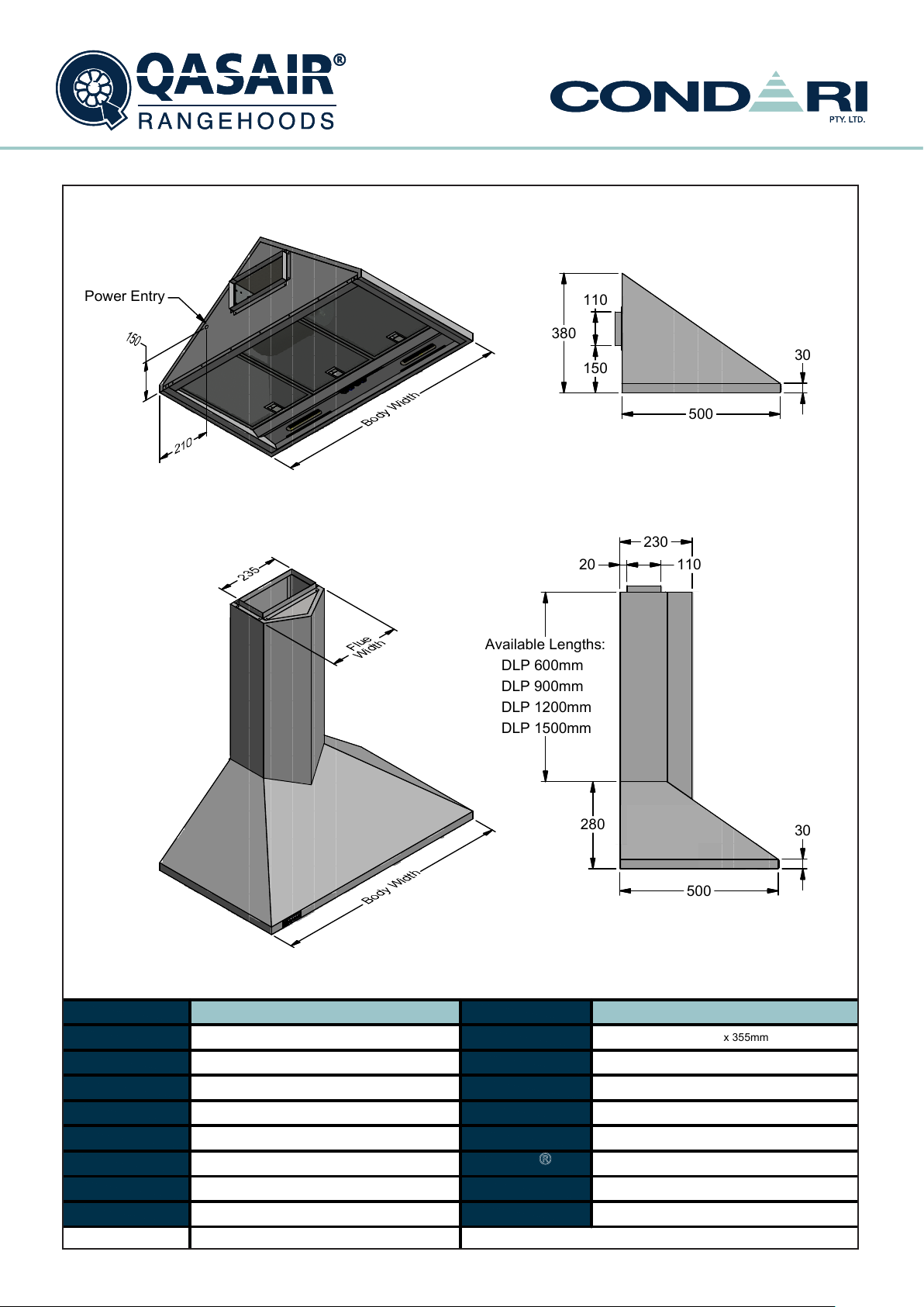
INSTALLATION INSTRUCTIONS
• BRH / LAM
Installation must be carried out by the procedure outlined.
Failure to do so may void the guarantee.
Electrical: Wiring to the appliance must comply with State and local Regulations.
Connection to be carried out by a registered electrician.
• BAR
• MAR
• MAJ
• FAS
1. Remove hood from packaging being careful not to touch stainless steel front.
2. Locate centre of stove and using level or plumb line, mark centre line up to ceiling.
3. Measure height of hood and mark same distance down from ceiling with level line.
4. Mark where ducting needs to be cut either on wall or ceiling, check for wires and timber, then cut hole for ducting.
5. Locate solid fixing points on wall (This hood is very heavy and requires good solid fixing points). If necessary fit
some solid fixing timber to wall behind hood now.
6. Mark fixing points on rear of hood and drill fixing holes to take solid screws.
7. Drill hole in rear or top of the hood to take electrical cable.
8. It may be easier to remove fans for easier fixing and weight when installing.
9. If you do not have adjustable stands you can cut some temporary timber props to sit canopy on when you lift into
position, to hold it while you fit fixing screws.
10. You need two people to lift this canopy into position. * Do not attempt this on your own, as you could cause
yourself injury and damage the hood or stove. CAUTION: Do not under any circumstances lift from the front of
the hood or put any pressure on the front face as you will damage the hood permanently.
11. Carefully lift hood into position and sit on stands to level hood, then screw hood into position through fixing holes.
Make sure you put fixing holes high up in the hood to stop it falling forward.
12. Fit ducting to hood to the outside atmosphere as required either through the roof with appropriate flashing by a
plumber or through the rear wall vent, which needs to be siliconed to the rear of the hood. Always use approved
ducting and seal all duct joins with duct tape or silicone.
13. An electrician should make the electrical connection to the hood by connecting to the 10 AMP junction box.
Ensure power is turned off during this procedure.
14. Refit fans to hood, insert filters and test.
Handy hints: Sometimes it is easier to lift the hood with a person in the roof space pulling up on a rope attached to a
wooden block placed inside base of hood and a second person down the bottom guiding the hood into position.
Qasair Rangehoods Installation Instructions28
Page 29

Version: C 20/01/2015F
m
m
Benton
Technical Specification Sheet
BRH
Wall Mounted
All
BENTON - BRH
Power entry location
is the same for all
Benton models.
H
510
-Thread rod
Model
Body Width
Motor Box /
Flue Width
Motor Qty
LED Light
Nightlight
Light Qty
Light Centres
Filter Qty
s are supplie
BRH 600L-1 BRH 900L-2BRH 900L-1BRH 600L-1BRH 900L-2BRH 900L-1
600mm
Cool
YES
310mm
Qasair Rangehoods Installation Instructions
d for extra support
N/A
1
2
2
900mm
N/A
1
Cool
YES
2
510mm
3
.
900mm
N/A
2
Cool
YES
2
510mm
3
Model
Filter Size
Conversion
Top/Back Back/Top
Electrical Connection
Minimum Height
(H =)
Maximum Height
(H =)
PowderKote
Available
All-thread
Fixing Centres
Corner Type
Condari Pty Ltd. Page 1 of 2
x 355mm
272mm
NO
Junction Box
400mm
1450mm
YES
500mm
Square
x 355mm
272mm
NO
Junction Box
400mm
1450mm
YES
800mm
Square
272mm
NO
Junction Box
400mm
1450mm
YES
800mm
Square
x 355
29
Page 30

Benton
Technical Specification Sheet
BRH
Wall Mounted
All
BENTON - BRH
Power entry location
is the same for all
Benton models.
250
7
5
250
H
2
0
510
-Thread rod
Model
Body Width
Motor Box /
Flue Width
Motor Qty
LED Light
Nightlight
Light Qty
Light Centres
Filter Qty
s are supplie
BRH 1000L-2
d for extra support
1000mm
N/A
Cool
2
510mm
3
.
BRH 1200L-2
1200mm
N/A
22
Cool
YESYES
2
648mm
4
Model
Filter Size
Conversion
Top/Back Back/Top
Electrical Connection
Minimum Height
(H =)
Maximum Height
(H =)
PowderKote
Available
All-thread
Fixing Centres
Corner Type
Condari Pty Ltd.
BRH 1000L-2
355mm
x
290mm
NO
Junction Box Junction Box
400mm
1450mm
YES
800mm
Square
Version: C 20/01/2015F
BRH 1200L-2
272mm
Page 2 of 2
x
NO
400mm
1450mm
YES
950mm
Square
355mm
Qasair Rangehoods Installation Instructions30
Page 31

Lamont
Technical Specification Sheet
LAM
Wall Mounted
Version: B 20/01/2015
A
l
LAMONT - LAM
Power entry location
is the same for all
Lamont models.
H
510
l-Threa
Model
Body Width
Motor Box /
Flue Width
Motor Qty
LED Light
Nightlight
Light Qty
Light Centres
Filter Qty
d rod
s are supplie
LAM 900L-1
Qasair Rangehoods Installation Instructions
d for extra support
900mm
N/A
1
Cool
YES
2
510mm
3
.
LAM 900L-2
900mm
N/A
2
Cool
YES
2
510mm
3
Model
Filter Size
Conversion
Top/Back Back/Top
Electrical Connection
Minimum Height
(H =)
Maximum Height
(H =)
PowderKote
Available
All-thread
Fixing Centres
Corner Type
Condari Pty Ltd.
LAM 900L-1
x 355mm
272mm
NO
Junction Box
1100mm
N/A
800mm
Square
272mm
Junction Box
F
Page 1 of 2
LAM 900L-2
x 355mm
NO
400mm400mm
1100mm
N/A
800mm
Square
31
Page 32

Lamont
Technical Specification Sheet
LAM
Wall Mounted
Version: B 20/01/2015F
A
l
LAMONT - LAM
Power entry location
is the same for all
Lamont models.
250
7
5
250
H
2
0
510
l-Threa
Model
Body Width
Motor Box /
Flue Width
Motor Qty
LED Light
Nightlight
Light Qty
Light Centres
Filter Qty
d rod
s are supplie
LAM 1000L-2
d for extra support
1000mm
N/A
Cool
2
510mm
3
.
LAM 1200L-2
1200mm
N/A
22
Cool
YESYES
2
648mm
4
Model
Filter Size
Conversion
Top/Back Back/Top
Electrical Connection
Minimum Height
(H =)
Maximum Height
(H =)
PowderKote
Available
All-thread
Fixing Centres
Corner Type
Condari Pty Ltd.
LAM 1000L-2
x 355mm
290mm
NO
Junction Box Junction Box
400mm
1100mm
N/A
800mm
Square
LAM 1200L-2
272mm
400mm
1100mm
950mm
Square
Page 2 of 2
x
NO
N/A
355mm
Qasair Rangehoods Installation Instructions32
Page 33

Barclay
Technical Specification Sheet
BAR
Wall Mounted
Version: B 20/01/2015F
BARCLAY - BAR
2
7
5
0
250
H
510
250
100
Power entry location
is the same for all
Barclay models.
Model BAR 2400-3000L-2
Body Width
Motor Box /
Flue Width
Motor Qty
LED Light
Nightlight
Light Qty
Light Centres
Filter Qty
BAR 1800-2400L-2
1800mm-2400mm
900mm,1000mm,1200mm
2
YES
Varies depending on
length of rangehood
Varies depending on
length of rangehood
Varies depending on
length of rangehood
900mm,1000mm,1200mm
2
CoolCool
YES
Varies depending on
length of rangehood
Varies depending on
length of rangehood
Varies depending on
length of rangehood
Optiona
l Desig
Model
Filter Size2400mm-3000mm
Conversion
Top/Back Back/Top
Electrical Connection
Minimum Height
(H =)
Maximum Height
(H =)
PowderKote
Available
All-thread
Fixing Centres
Corner Type
Condari Pty Ltd.
n
Motor Box can be
either L/H or R/H.
BAR 1800-2400L-2
Varies depending on
length of rangehood
NO
Junction Box
550mm
m
m
1550
N/A
N/A
Square
BAR 2400-300L-2
Varies depending on
length of rangehood
NO
Junction Box
550mm
1550mm
N/A
N/A
Square
Page 1 of 1
Qasair Rangehoods Installation Instructions
33
Page 34

m
m
Martell
Technical Specification Sheet
MAR
Wall Mounted
MARTELL - MAR
Power entry location
is the same for all
Martell models.
2
0
110
2
0
500
300
110
700
148
510
Model
Body Width
Motor Box /
Flue Width
Motor Qty
LED Light
Nightlight
Light Qty
Light Centres
Filter Qty
MAR 900L-1 MAR 1200L-2MAR 900L-2MAR 900L-1MAR 1200L-2MAR 900L-2
900mm
N/A
1
Cool
YES
2
422mm
2
900mm
N/A
2
Cool
YES
2
422mm
2
1200mm
N/A
2
Cool
YES
2
544mm
4
Model
Filter Size
Conversion
Top/Back Back/Top
Electrical Connection
Minimum Height
(H =)
Maximum Height
(H =)
PowderKote
Available
All-thread
Fixing Centres
Corner Type
Condari Pty Ltd. Page 1 of 2
x 272mm
422mm
NO
Junction Box
N/A
N/A
N/A
N/A
Square
Version: A 01/07/2014F
422mm
Junction Box
x 272mm
NO
N/A
N/A
N/A
N/A
Square
272mm
NO
Junction Box
N/A
N/A
N/A
N/A
Square
x 272
Qasair Rangehoods Installation Instructions34
Page 35

Martell
Technical Specification Sheet
MAR
Wall Mounted
Version: A 01/07/2014F
MARTELL - MAR
Power entry location
is the same for all
Martell models.
2
0
110
2
0
500
300
110
700
148
510
Model
Body Width
Motor Box /
Flue Width
Motor Qty
LED Light
Nightlight
Light Qty
Light Centres
Filter Qty
MAR 1500L-3
1500mm
N/A
3
Cool
YES
2
816mm
5
Qasair Rangehoods Installation Instructions
MAR 1800L-3
1800mm
N/A
3
YES
4
422mm
4
Model
Filter Size
Conversion
Top/Back Back/Top
Electrical Connection
Minimum Height
(H =)
Maximum Height
(H =)
PowderKote
Available
All-thread
Fixing Centres
Corner Type
Condari Pty Ltd.
MAR 1500L-3
x 272mm
272mm
NO
Junction Box
N/ACool
N/A
N/A
N/A
Square
MAR 1800L-3
422mm
Junction Box
Square
Page 2 of 2
x 272mm
NO
N/A
N/A
N/A
N/A
35
Page 36

Majestic
Technical Specification Sheet
MAJ Wall Mounted
Condari Pty Ltd.
Version: B 29/11/2014F
Page 1 of 2
m
m
All
-
MAJESTIC - MAJ
Power entry location
is the same for all
Majestic models.
500
H
150
300
Threa
d rod
s are supplie
Model MAJ 900L-1
Body Width
Motor Box /
Flue Width
Motor Qty
LED Light
Nightlight
Light Qty
Light Centres
Filter Qty
d for extra support
MAJ 900L-1
900mm
N/A
1
Cool
YES
2
350mm
3
MAJ 900L-2
900mm
N/A
Cool
350mm
3
.
1000mm
N/A
22
Cool
YESYES
22
350mm
2
ModelMAJ 1000L-2
Filter Size
Conversion
Top/Back Back/Top
Electrical Connection
Minimum Height
(H =)
Maximum Height
(H =)
PowderKote
Available
All-thread
Fixing Centres
Corner Type
MAJ 900L-2
x 272mm
272mm
NO
Junction BoxNOJunction Box
600mm
1150mm
N/A
600mm
Square Square
x 272mm
272mm
600mm
1150mm 1150mm
N/A
600mm 600mm
MAJ 1000L-2
x
422mm
NO
Junction Box
600mm
N/A
Square
272
Qasair Rangehoods Installation Instructions36
Page 37

Majestic
Technical Specification Sheet
MAJ Wall Mounted
All
-
MAJESTIC - MAJ
Power entry location
is the same for all
Majestic models.
500
H
150
300
Threa
d rod
s are supplie
Model
Body Width
Motor Box /
Flue Width
Motor Qty
LED Light
Nightlight
Light Qty
Light Centres
Filter Qty
d for extra support
1200mm
N/A
Cool
YES
2
500mm
4
.
MAJ 1500L-2
1500mm
N/A
22
Cool
YES
2
600mm
5
Model
Filter Size
Conversion
Top/Back Back/Top
Electrical Connection
Minimum Height
(H =)
Maximum Height
(H =)
PowderKote
Available
All-thread
Fixing Centres
Corner Type
MAJ 1200L-2MAJ 1200L-2
x 272mm
272mm
NO
Junction Box
600mm
1150mm
N/A
800mm
Square
Version: B 29/11/2014F
MAJ 1500L-2
272mm
Junction Box
Page 2 of 2Condari Pty Ltd.
x 272mm
NO
600mm
1150mm
N/A
1100mm
Square
Qasair Rangehoods Installation Instructions
37
Page 38

Fasano
Technical Specification Sheet
FAS
Wall Mounted
Version: C 20/01/2015F
FASANO - FAS
Power entry location
is the same for all
Fasano models.
360
250
7
5
5
0
250
H
510
All-Thread rods are supplied for extra support
.
Model FAS 1200L-2
Body Width
Motor Box /
Flue Width
Motor Qty
LED Light
Nightlight
Light Qty
Light Centres
Filter Qty
FAS 900L-2
900mm
N/A
2
YES
2
510mm
3
N/A
2
CoolCool
YES
2
648mm
4
Model
Filter Size1200mm
Conversion
Top/Back Back/Top
Electrical Connection
Minimum Height
(H =)
Maximum Height
(H =)
PowderKote
Available
All-thread
Fixing Centres
Corner Type
Condari Pty Ltd.
272mm
Junction Box
300mm
Qasair Rangehoods Installation Instructions38
FAS 900L-2
x 355mm
NO
700mm
m
m
1400
YES
x 500mm
Square
FAS 1200L-2
272mm
Junction Box
700mm
1400mm
YES
300mm
Square
Page 1 of 1
x 355mm
NO
x 800mm
Page 39

REMOTE SWITCHING SPECIFICATIONS
3 FAN (no lights)
1. Wiring to the appliance must comply with State and local regulations.
2. Switching is not provided with this unit. - The order was for the controls to be separate from the unit.
3. You may use any switching to connect the rangehood (e.g. Clipsal switches).
4. All fans must be controlled by at least one ON/OFF and one HI/LO switch.
(i.e. single or twin motor models).
5. Please refer to Wiring Diagram below for detailed wiring information.
WIRING DIAGRAM
-------------------- CABLES TO REMOTE SWITCHES --------------------
NOTES:-
ALL FANS MUST BE CONTROLLED
1. IT IS NECESSARY TO PROVIDE
BY AT LEAST ONE ON/OFF AND
AN ON/OFF AND A HIGH/LOW
ONE HI/LO SWITCH.
SWITCH FOR EACH FAN.
2. THE WIRING FOR THE FANS ARE 4 CORE LOW SPEED - BROWN
HIGH SPEED - WHITE
NEUTRAL - BLUE
EARTH - GREEN
BLUE
WHITE
BROWN
GREEN
BLUE
WHITE
BROWN
GREEN
BLUE
WHITE
GREEN
JUNCTION
BOXES
BLUE
BROWN BROWN
BLACK
BLUE
BROWN
BLACK
JUNCTION
BOXES
BLUE
BROWN
BLACK
NOTE: This diagram is for reference only. A qualied elecrician must connect remote
switching to rangehood.
Reected in this drawing is the most common method of connecting the rangehood.
Be aware that Active voltage must NOT be applied to both the ‘White- High’ or
‘Brown-Low’ wires at the same time. This will cause the fan to fail.
Qasair Rangehoods Installation Instructions
39
Page 40

REMOTE SWITCHING SPECIFICATIONS
‘Brown-Low’ wires at the same time. This will cause the fan to fail.
3 FAN, LED and NIGHTLIGHT
1. Wiring to the appliance must comply with State and local regulations.
2. Switching is not provided with this unit. - The order was for the controls to be separate from the unit.
3. You may use any switching to connect the rangehood (e.g. Clipsal switches).
4. All fans must be controlled by at least one ON/OFF and one HI/LO switch.
(i.e. single or twin motor models).
5. Please refer to Wiring Diagram below for detailed wiring information.
WIRING DIAGRAM
ALL FANS MUST BE CONTROLLED
BY AT LEAST ONE ON/OFF AND
ONE HI/LO SWITCH.
NOTE: This diagram is for reference only. A qualied elecrician must connect remote
switching to rangehood.
Reected in this drawing is the most common method of connecting the rangehood.
Be aware that Active voltage must NOT be applied to both the ‘White- High’ or
Qasair Rangehoods Installation Instructions40
Page 41

REMOTE SWITCHING SPECIFICATIONS
22/08/2013
3 FAN with LED
1. Wiring to the appliance must comply with State and local regulations.
2. Switching is not provided with this unit. - The order was for the controls to be separate from the unit.
3. You may use any switching to connect the rangehood (e.g. Clipsal switches).
4. All fans must be controlled by at least one ON/OFF and one HI/LO switch.
(i.e. single or twin motor models).
5. Please refer to Wiring Diagram below for detailed wiring information.
WIRING DIAGRAM
-------------------- CABLES TO REMOTE SWITCHES --------------------
GREEN
WHITE
BROWN
BLUE
BLACK
BROWN
BLUE
CIRCUIT DIAGRAM
AC1 AC2
LED
BLUE
BLUE
BLUE
BLUE
BROWN
BROWN
BROWN
BROWN
BLUE
BROWN
BLUE
JUNCTION
BOXES
AC2
LED
GREEN
WHITE
BROWN
BLUE
JUNCTION
BOXES
BROWN
BLACK
BLUE
AC1
GREEN
WHITE
BROWN
BLUE
JUNCTION
BLACK
BROWN
BLUE
CONDARI PTY LTD
8 Argent Place, Ringwood VIC 3134
Ph: (03) 9873 5877 / Fx: (03) 9873 5748
BOXES
NOTE: This diagram is for reference only. A qualied elecrician must connect remote
switching to rangehood.
Reected in this drawing is the most common method of connecting the rangehood.
Be aware that Active voltage must NOT be applied to both the ‘White- High’ or
‘Brown-Low’ wires at the same time. This will cause the fan to fail.
NOTES:-
1. IT IS NECESSARY TO PROVIDE
ALL FANS MUST BE CONTROLLED BY
AN ON/OFF AND A HIGH/LOW
AT LEAST ONE ON/OFF AND ONE
SWITCH FOR EACH FAN.
HI/LO SWITCH.
2. THE WIRING FOR THE FANS ARE 4 CORE LOW SPEED - BROWN
HIGH SPEED - WHITE
NEUTRAL - BLUE
EARTH - GREEN
3. THE WIRING FOR THE LIGHTS IS 2 CORE ACTIVE - BROWN
NEUTRAL - BLUE
DESIGNER
M. Brewin
CHECKED
M. Malesevic REVISION
DATE
A
Qasair Rangehoods Installation Instructions
41
Page 42

SINGLE MOTOR DUCTING
NOTE:
This Zinc Alume Strip is provided to join some duct pieces together.
It will be clearly shown on the drawing of the piece it is supplied with.
I/I: Inside to Inside Measurement
101. DL-1 Single Motor Duct Length 1200mm
DL-1 CB Single Motor Duct
Back Draft Wall Vent Single Motor Horizontal
1200mm Colourbond
Horizontal Bend Single Motor 90º
102. HB-1
105. BD/WV-H-1 SS
445M2 Stainless Steel
Length
Single Motor Duct Length 300mm
Horizontal Bend Single Motor 45º
Vertical Bend Single Motor 90º
101. DL-1 A
103. HB-1/45
106. VB-1
Single Motor Duct Length Extension
Back Draft Wall Vent Single Motor Horizontal
See alternative Duct Piece No. 145
Vertical Bend Single Motor 45º
101. DL-1 E
104. BD/WV-H-1
107. VB-1/45
Back Draft Wall Vent Single Motor
108. BD/WV-V-1
Vertical
Back Draft Wall Vent Single Motor Vertical
109. BD/WV-V-1 SS
445M2 Stainless Steel
Duct Director Single Motor Horizontal Left
110. DD-1H L
Qasair Rangehoods Installation Instructions42
Page 43

SINGLE MOTOR DUCTING
Duct Director Single Motor Horizontal
111. DD-1H R
Right
114. CD-920
Cavity Duct Extendible
117. DR-200
Duct Length 200Ø
Twisted Transition Single Motor
Duct Length 200Ø Colourbond
112. TT-1
115. CD-920 TO DL-1
Cavity Duct to DL-1
118. DR-200 CB
113. DLE-DLE
Flue Joiner Single Motor
Single Motor Transition DL-1 to 200Ø
116. TR-1
119. DR-200/45
200Ø Bend 45º
120. DR-200/90
200Ø Bend 90º
123. CH-200
Chairman’s Hat 200Ø
Qasair Rangehoods Installation Instructions
Back Draft Wall Vent Rear Register Kit to
121. BD-6/7/9-WV-R/R
Suit 6/7/900H
Chairman’s Hat 200Ø Colourbond
124. CH-200 CB
122. BD/WV-200Ø
Back Draft Wall Vent
Back Draft Roof Cowl Single Motor
125. BD/RC-1
43
Page 44

SINGLE MOTOR DUCTING
Back Draft Roof Cowl Single Motor
Wall Vent Cover Single Motor Horizontal
126. BD/RC-1 CB
Colourbond
Back Draft Damper Single Motor
129. BD/M-1
132. WVC-H-1 SS
445M2 Stainless Steel
Back Draft Roof Cowl Single Motor 200Ø
Wall Vent Cover Single Motor Vertical
127. BD/SQ-RC 200
130. CF 6/7/900H
Ceiling Flange to Suit 6/7/900H
133. WVC-V-1
Stainless Steel Flue Cap to Suit DLE
Wall Vent Cover Single Motor Horizontal
Wall Vent Cover Single Motor Vertical
128. DLE-S/S CAP
131. WVC-H-1
See alternative Duct Piece No. 145
134. WVC-V-1 SS
445M2 Stainless Steel
135. 6/7/900H-SC
Spiggot Cap to Suit 6/7/900H
Roof Cap 200Ø 445M2 Stainless Steel
138. RCP 200 SS
136. EV/DL-1
Eave Vent to Suit DL-1
Roof Cowl 200Ø 445M2 Stainless Steel
139. RC 200 SS
Wall Vent Cover to Suit Rear Register Kit
137. WVC-6/7/9H-R/R
for 6/7/900H
140. RC 200
Roof Cowl 200Ø
Qasair Rangehoods Installation Instructions44
Page 45

Roof Cowl Single Motor 445M2 Stainless Steel
400
75
250
141. RC 1 SS
WALL VENT
144. FRWV-V-1 SS
Fire Rated Wall Vent Vertical
445M2 Stainless Steel
142. FRC 200 SS
Fire Rated 200Ø Roof Cowl
445M2 Stainless Steel
I
/
I
2
4
2
4
8
0
I
WALL VENT
3
1
7
7
5
I
/
I
3
1
8
2
5
0
0
5
1
Back Draft Wall Vent & Cover Single Motor
Horizontal kit assembled as one piece
145. BD/WV/K-H-1
WALL VENT
143. FRWV-H-1 SS
Fire Rated Wall Vent Horizontal
445M2 Stainless Steel
0
1
1
I
/
ROOF COWLS, WALL VENTS
AND WALL VENT COVERS
All the above ducting pieces
are all made in stainless
steel type 445M2 which
has a chromium content of
22% which is far greater
than marine grade stainless
steel and provides better
protection.
This is stated on the
description of each piece in
the ducting brochure.
WALL VENT COVERS SPECIFICATIONS
FIRE RATED APPROVED
The wall vent covers have
stainless steel screening
type 316 and meets the
requirements for stainless
steel screening under the
Australian Standard.
Qasair Rangehoods Installation Instructions
AS 3959-2009 Construction
of Buildings in Bushfire
prone areas.
45
Page 46

TWIN MOTOR DUCTING
NOTE:
This Zinc Alume Strip is provided to join some duct
pieces together. It will be clearly shown on the drawing
of the piece it is supplied with.
I/I: Inside to Inside Measurement
201. TMT
Twin Motor Transition
Horizontal Bend Twin Motor 45º
204. HB-2/45
Vertical Bend Twin Motor 90º
207. VB-2
Twin Motor Duct Length 1200mm
Back Draft Wall Vent Twin Motor
Vertical Bend Twin Motor 45º
202. DL-2
205. BD/WV-H-2
Horizontal
208. VB-2/45
Horizontal Bend Twin Motor 90º
Back Draft Wall Vent Twin Motor Horizontal
203. HB-2
206. BD/WV-H-2 SS
445M2 Stainless Steel
Back Draft Wall Vent Twin Motor Vertical
209. BD/WV-V-2
Back Draft Wall Vent Twin Motor Vertical
210. BD/WV-V-2 SS
445M2 Stainlerss Steel
Twisted Transition Twin Motor
211. TT-2
212. DLE-2 TO DLE-2
Flue Joiner Twin Motor
Qasair Rangehoods Installation Instructions46
Page 47

TWIN MOTOR DUCTING
213. BD-10/12/15-WV-R/R
Back Draft Wall Vent 10/12/1500H
216. DR-300
Duct Length 300Ø
219. DR-300/90
300Ø Bend 90º
214. TMT-300
Twin Motor Transition to 300Ø
217. DR-300 CB
Duct Length 300Ø Colourbond
Twin Motor Transition DL-2 to 250SQ
220. DL-2/250SQ
Twin Motor Transition from DL-2 to 300Ø
Twin Motor Transition 250SQ to 300Ø
215. TR-2
218. DR-300/45
300Ø Bend 45º
221. TMT-250/300
Twin Motor Transition to 250SQ
222. TMT-250
225. HB-250/45
Horizontal Bend 250SQ 45º
Qasair Rangehoods Installation Instructions
223. DL-250
Duct Length 250SQ
226. TMT-250/90 L
Duct Deflector 250SQ Left
224. HB-250
Horizontal Bend 250SQ 90º
227. TMT-250/90 R
Duct Deflector 250SQ Right
47
Page 48

TWIN MOTOR DUCTING
228. BD/WV-250 SQ
Back Draft Wall Vent 250SQ
231. BD/RC-2 CB
Back Draft Roof Cowl Twin Motor
Colourbond
234. BD/SQ-RC 300
Back Draft Roof Cowl 300Ø
229. BD/WV-250 SQ SS
Back Draft Wall 250SQ 445M2 Stainless
Back Draft Roof Cowl 250SQ
Steel
232. CH-300
Chairman’s Hat 300Ø
235. BD/RC-250 SQ
Back Draft Roof Cowl Twin Motor
Chairman’s Hat 300Ø Colourbond
Stainless Steel Flue Cap to Suit DLE-2
230 BD/RC-2
233. CH-300 CB
236. DLE-2-S/S CAP
237. CF 10/12/1500H
Ceiling Flange to Suit 10/12/1500H
240. CF 4F-900-2
Ceiling Flange to Suit 4F 900-2
238. CF 3F-900-2
Ceiling Flange to Suit 3F 900-2
241. CF 4F-1200-2
Ceiling Flange to suit 4F 1200-2
239. CF 3F-1200-2
Ceiling Flange tp suit 3F 1200-2
Wall Vent Cover Twin Motor Horizontal
242. WVC-H-2
Qasair Rangehoods Installation Instructions48
Page 49

TWIN MOTOR DUCTING
Wall Vent Cover Twin Motor Horizontal
243.WVC-H-2 SS
445M2 Stainless Steel
246. WVC-250 SQ
Wall Vent Cover 250SQ
249. 10/12/15H-SC
Spiggot Cap to Suit 10/12/1500H
Wall Vent Cover Twin Motor Vertical
Wall Vent Cover 250SQ 445M2 Stainless
Duct Director Twin Motor Horizontal Left
244. WVC-V-2
247. WVC-250 SQ SS
Steel
250. DD-2H-L
Wall Vent Cover Twin Motor Vertical
Wall Vent Cover to suit 10/12/1500H
Duct Director Twin Motor Horizontal Right
245. WVC-V-2 SS
445M2 Stainless Steel
248. WVC-10/12/15H-R/R
251. DD-2H-R
Duct Director Twin Motor Vertical Left
Back Draft Damper Twin Motor 250SQ
252. DD-2V-L
255. BD/M-250SQ
Qasair Rangehoods Installation Instructions
Duct Director Twin Motor Vertical Right
253. DD-2V-R
256. BD/WV-300Ø
Back Draft Wall Vent
254. EV/DL-2
Eave Vent to Suit DL-2
257. BD/WVC-SBS
Twin Motor Wall Vent Deflector
49
Page 50

TWIN MOTOR DUCTING
75
400
250
EXTENDED
250
75
400
EXTENDED
6
7
5
258. CF 3F-1500-2
Ceiling Flange to Suit 3F 1500-2
Roof Cowl 300Ø 445M2 Stainless Steel
Fire Rated Wall Vent Twin Motor Horizontal
I
/
I
6
5
Kit assembled as one piece. Two Single Motor
261. RC 300 SS
264. FRWV-H-2 SS
445M2 Stainless Steel
5
2
5
3
9
5
2
5
0
0
267. BD/WV/K-H-2
Back Draft Wall Vent Horizontal
with telescopic length & cover
I
/
I
0
4
2
I
/
I
0
1
1
2
4
8
Roof Cap 300Ø 445M2 Stainless Steel
Roof Cowl Twin Motor 445M2 Stainless
259. RCP 300 SS
262. RC 2 SS
Steel
WALL VENTWALL VENT
Fire Rated Wall Vent Twin Motor Vertical
I
/
I
7
5
Kit assembled as one piece. Fire rated Two
Single Motor Back Draft Wall Vent Horizontal
265. FRWV-V-2 SS
445M2 Stainless Steel
6
5
2
6
5
3
2
5
0
0
5
268. FRWV/K-H-2
with telescopic length & cover
9
5
I
/
I
0
4
2
I
/
I
0
1
1
2
4
8
WALL VENTWALL VENT
Roof Ventilation Cowl 300Ø 445M2
260. RV 300 SS
Stainless Steel
263. FRC 300 SS
Fire Rated Roof Cowl 300Ø
445M2 Stainless Steel
WALL VENT
Fire Rated Wall Vent Twin Motor 250SQ
266. FRWV-250 SQ SS
445M2 Stainless Steel
ROOF COWLS, WALL VENTS
AND WALL VENT COVERS
All the above ducting pieces
are all made in stainless
steel type 445M2 which
has a chromium content of
22% which is far greater
than marine grade stainless
steel and provides better
protection.
This is stated on the
description of each piece in
the ducting brochure.
WALL VENT COVERS SPECIFICATIONS
FIRE RATED APPROVED
The wall vent covers have
stainless steel screening
type 316 and meets the
requirements for stainless
steel screening under the
Australian Standard.
AS 3959-2009 Construction
of Buildings in Bushfire
prone areas.
Qasair Rangehoods Installation Instructions50
Page 51

TRIPLE MOTOR DUCTING
NOTE:
This Zinc Alume Strip is provided to join some duct pieces together.
It will be clearly shown on the drawing of the piece it is supplied with.
I/I: Inside to Inside Measurement
301. 3MT-DL-3
Three Motor Transition to DL-3
Horizontal Bend Triple Motor 45º
Triple Motor Twisted Transition
304. HB-3/45
307. TT-3
302. DL-3
Triple Motor Duct Length
Vertical Bend Triple Motor 90º
Triple Motor Transition DL-3 to 350Ø
305. VB-3
308. TMT-400x200/350
Horizontal Bend Triple Motor 90º
Vertical Bend Triple Motor 45º
Triple Motor Transition to 350Ø
303. HB-3
306. VB-3/45
309. TR-3
310. DR-350
Duct Length 350Ø
Qasair Rangehoods Installation Instructions
311. DR-350 CB
Duct Length 350Ø Colourbond
312. DR-350/45
350Ø Bend 45º
51
Page 52

TRIPLE MOTOR DUCTING
313. DR-350/90
350Ø Bend 90º
Back Draft Roof Cowl Triple Motor 350SQ
316. BD/SQ-RC 350
319. CH-350 CB
Chairmans Hat 350Ø Colurbond
Back Draft Roof Cowl Triple Motor
Back Draft Wall Vent Triple Motor Horizontal
314. BD/RC-3
317. BD/SQ-RC 350 SS
Back Draft Roof Cowl 350Ø
445M2 Stainless Steel
320. BD/WV-H-3
Back Draft Roof Cowl Triple Motor
Back Draft Wall Vent Triple Motor Horizontal
315. BD/RC-3 SS
445M2 Stainless Steel
318. CH-350
Chairmans Hat 350Ø
321. BD/WV-H-3 SS
445M2 Stainless Steel
Back Draft Wall Vent Triple Motor Vertical
Wall Vent Cover Triple Motor Horizontal
322. BD/WV-V-3
325.WVC-H-3 SS
445M2 Stainless Steel
Back Draft Wall Vent Triple Motor Vertical
Wall Vent Cover Triple Motor Vertical
323. BD/WV-V-3 SS
445M2Stainless Steel
326. WVC-V-3
Wall Vent Cover Triple Motor Horizontal
Wall Vent Cover Triple Motor Vertical
324. WVC-H-3
327. WVC-V-3 SS
445M2 Stainless Steel
Qasair Rangehoods Installation Instructions52
Page 53

TRIPLE MOTOR DUCTING
0
75
EXTENDED
9
I
1
EXTENDED
9
5
I
Duct Director Triple Motor Vertical Left
328. DD-3V-L
WALL VENT
331. FRWV-H-3 SS
Fire Rated Wall Vent Triple Motor
/
I
9
8
8
7
5
Kit assembled as one piece. Three Single
Motor Back Draft Wall Vent Horizontal
with telescopic length & cover
Horizontal
8
7
9
5
0
334. BD/WV/K-H-3
9
5
I
/
I
0
4
2
I
/
I
0
1
1
2
4
8
2
5
0
WALL VENT WALL VENT
Duct Director Triple Motor Vertical Right
329. DD-3V-R
WALL VENT
Fire Rated Wall Vent Triple Motor Vertical
/
I
7
5
Kit assembled as one piece. Fire rated Three
Single Motor Back Draft Wall Vent Horizontal
332. FRWV-V-3 SS
8
7
9
8
8
9
5
0
5
335. FRWV/K-H-3
with telescopic length & cover
9
5
I
/
I
0
4
2
/
I
1
1
2
4
8
2
5
0
330. BD/WV-350Ø
Back Draft Wall Vent
Fire Rated Roof Cowl 350Ø 445M2
I
333. FRC 350 SS
Stainless Steel
ROOF COWLS, WALL VENTS
AND WALL VENT COVERS
All the above ducting pieces
are all made in stainless
steel type 445M2 which
has a chromium content of
22% which is far greater
than marine grade stainless
steel and provides better
protection.
This is stated on the
description of each piece in
the ducting brochure.
WALL VENT COVERS SPECIFICATIONS
FIRE RATED APPROVED
The wall vent covers have
stainless steel screening
type 316 and meets the
requirements for stainless
steel screening under the
Australian Standard.
AS 3959-2009 Construction
of Buildings in Bushfire
prone areas.
Qasair Rangehoods Installation Instructions
53
Page 54

INSTALLATION IDEAS
Condari recommends Qasair and Condor Rangehoods be installed using ducting that is:
• rigid
• non-ammable
• correctly sized
to ensure maximum air movement and minimum noise levels.
Ducting incorrectly with exible or smaller diameter ducting will dramatically reduce the air movement
and increase the noise level of the rangehood and will void the manufacturer’s warranty.
The Installation Ideas below will give you some guidelines on how to correctly duct your Qasair and
Condor Rangehood using Qasair and Condor ducting pieces.
FA 60L-1 T
Rangehood
3. FA 60L-1 T 4. FA 60L-1 T
FA 60L-1 T
Rangehood
5. FA 60L-1 T
6. FA 60L-1 T / FA 60L-1 B
FA 60L-1 T
Rangehood
FA 60L-1 T
FA 60L-1 B
Rangehood
Qasair Rangehoods Installation Instructions54
Page 55

FA 90L-2 T
Rangehood
FA 90L-2 T
Rangehood
7. FA 90L-2 T 8. FA 90L-2 T
FA 90L-2 B
Rangehood
FA 90L-2 T
Rangehood
9. FA 90L-2 T 10. FA 90L-2 B
FA 90L-2 T
Rangehood
11. FA 90L-2 T 12. FA 90L-2 T
Qasair Rangehoods Installation Instructions
FA 90L-2 T
Rangehood
55
Page 56

600HL-1 T / 700HL-1 T / 900HL-1 T
Rangehood
13. 600HL-1 T / 700HL-1 T / 900HL-1 T 14. 600HL-1 T
600HL-1 T Rangehood
CON 60L-1 T Rangehood
15. CON 60L-1 T 16. CON 80L-1 T
17. CON 60L-1 T 18. CON 80L-2 T
CON 80L-1 T Rangehood
CON 80L-2 T RangehoodCON 60L-1 T Rangehood
Qasair Rangehoods Installation Instructions56
Page 57

1200HL-2 T
Rangehood
19. 1200HL-2 T 20. LIS 800L-2 T
LIS 800L-2 T
Rangehood
21. LIS 1000L-2 T 22. 3F 900L-2 T / 1200L-2 T
LIS 500L-1 T
Rangehood
23. LIS 500L-1 T 24. LIS 800L-1 T
Qasair Rangehoods Installation Instructions
LIS 1000L-2 T
Rangehood
3F 900L-2 T / 1200L-2 T
Rangehood
LIS 800L-1 T
Rangehood
57
Page 58

LIS 1200L-2 B
Rangehood
CON 80L-1 T
Rangehood
FA-90L-1 T
Rangehood
LIS 1000L-2 T
Rangehood
25. CON 80L-1 T / LIS 1000-2 T 26. LIS 1200L-2 B
FA-60L-1 B
Rangehood
1. FA 60L-1 B2. FA 90L-1 T
Qasair Rangehoods Installation Instructions58
Page 59

OPERATION DETAILS
Light ON and OFF
Light High and Low
Fan Left Side ON and OFF
Fan Left Side High and Low
Right Side Fan/s ON and OFF
Right Side Fan/s High and Low
RANGEHOOD CLEANING
Qasair Rangehoods are made from stainless steel, either type 304 or type 316.
* Type 304 is classied as 18/8 stainless steel
* Type 316 is classied as 18/10 stainless steel
This means that the stainless steel is made of 18% nickel and either 8% or 10% of chromium respectively.
Stainless steel gets its protective coating from the chromium oxidising in the air to form a protective surface
of chromium oxide. This can be attacked by different substances, such as salt water or sea air. The stainless
steel will start to show pit marks which are referred to in the industry as tea staining. This will happen to
marine grade stainless steel type 316 in the same way it will happen to stainless steel type 304, it will just
take longer to happen.
The way to overcome this is to clean the stainless steel with warm soapy water and then polish it with a cloth
so that the chromium will oxidise again.
When exposed to sea water or sea side conditions this is only a stop gap measure as the attack will start
again.
With stainless steel rangehoods exposed in Alfresco areas we recommend spraying the hood with vegetable
oil and rubbing it all over the rangehood, if it is going to be unused over a period of time.
FILTER CLEANING
For the best results, please clean filters regularly.
Condari recommends cleaning filters once per month, or immediately after heavy use.
You can do this by hand washing in warm soapy water, or by placing filters in the top rack of the
dishwasher using a detergent of pH 8 or less.
Note: Washing the filters in the dishwasher may cause discolouration of the filters.
We recommend washing filters in the dishwasher without detergent or use one of the powder
detergent.
Ensure the filters are completely dry before placing them back.
Do not operate the rangehood without the filters installed.
Condari does not recommend the use of corrosive, caustic or acidic products, particulary industrial
or citric products.
Condari has experienced problems with many of the dishwashing detergents now on the market.
Particularly with the tablet type detergents as many come from overseas, which are made for a hard
water environment. We have found that these detergents have a deleterious effect on the filters and
the result is that the filters last for about 50 to 60 washes.
This is equivalent to about 5 to 6 years life.
Qasair Rangehoods Installation Instructions
59
Page 60

CONDARI PTY LTD APPLIANCE GUARANTEE
The benefits conferred by this warranty are in addition to all other rights and remedies in respect of the product
which the consumer has under the Competition and Consumer Act 2010 and similar state and territory laws.
Condari P/L in Melbourne (and by their agency in Country Areas and other States) warrants that the appliance
will be free from defects in materials and workmanship for a period of 36 months from the date of purchase of
the appliance to the consumer.
If there is a breach of this warranty, Condari will rectify, free of charge, at it’s nearest service centre or
authorised service agency any fault caused by faulty workmanship or material at the time of manufacture
occurring in the appliance within 36 months from the date of purchase of the appliance to the customer.
This warranty is conditional upon the appliance being used only for personal, domestic and household purposes
and installed and operated in accordance with QASAIR Instructions and does not apply to articles which by their
nature are consumable.
If a defect is caused by neglect, misuse, or failure to follow operating instructions where special precautions are
detailed for user attention then a charge shall be made for the service call.
For example:
With the filters the user is specifically requested:
• To clean filter regularly by handwashing or placing in a dishwasher at least once a month.
• To turn rangehood off after each use.
• Note: Warranty under filter cleaning on page 59
Where a claim is made under warranty, CONDARI reserves the right to determine whether or not the fault is
caused by faulty workmanship or material or that the part is defective.
The consumer shall be fully responsible for all expenses whatsoever incidental to the removal of parts from
the unit or to their replacement. Amongst other things, such responsibility shall extend to damaged walls, tiles,
fixtures and fittings whether or not the unit has been built into a cupboard and irrespective of the stage either of
its installation or the fitting of any other item whatsoever in its vicinity.
No other person, or firm or corporation is authorised by Condari to offer or give on its behalf any other greater
warranty than that given by Condari under this warranty.
Condari Pty Ltd provides to all QASAIR Rangehoods a 10 year motor replacement warranty. This is a change
over warranty.
The installation of the rangehood must comply with the information in this guide. Failure to follow the instructions
may result in loss of the warranty.
We do point out that incorrect installation such as the ducting being the incorrect size or the duct run being too
long will result in the motor failing and possible burning out.
The change over will be carried out by a authorized technician and will be charged at the rates applicable at
time of the change over.
Qasair Rangehoods Installation Instructions60
Page 61

EXCLUSIONS
There are some exclusions from the Condari Pty Ltd Guarantee. (on previous page)
CONDOR Rangehoods are designed to be used over all domestic barbecues available
in AUSTRALIA.
QASAIR Rangehoods are not to be used over barbecues approved for outdoor use only.
Outdoor barbecues will have a rating plate on them specifying that they are approved for outdoor use only and
also a mega joule rating per burner or a total mega joule rating.
In practice any barbecue or outdoor cooking appliance over 50 mega joule will need a specially made
rangehood with an air movement exceeding 2000 cubic meters per hour.
QASAIR have hoods to go over domestic cookers such as VIKING, WOLF and CAPITAL cooking appliances.
These brands have a mega joule rating of up to 95 mj and therefore special hoods are required for the
appliances.
CONDARI will manufacture special rangehoods to go over commercial cooking appliances situated in domestic
kitchens.
Once the heat output is over 50 mega joule a special rangehood is required.
Qasair Rangehoods Installation Instructions
61
Page 62

STANDARD
WARRANTY
Date purchased
Purchased from
Model
Serial No
The purchaser must fill in the above information and keep this with the original purchase document.
This form must be produced if and when
a claim is made under this warranty.
QASAIR Rangehoods are made in Ringwood, Australia.
Tel: +61 3 9482 7088
Fax: +61 3 9482 7011
Email: sales@condari.com.au
Pleae Note that the Warranty is from the date of installation and the service technician will need to see proof of
purchase so he can provide service under the guarantee.
If no proof of purchase then the service call will be charged at standard rates and if proof provided later,
reimbursement will be made.
Qasair Rangehoods Installation Instructions62
Page 63

EXTENDED
WARRANTY
Condari Pty Ltd provides an extended warranty from 36 months to 72 months if installed by an authorised
Qasair installer and the below form is completed.
The authorised installer also offers a warranty on their workmanship for the same period of 72 months with a
guarantee that the installation is in compliance with
‘Qasair installation instructions’.
Customer Name:
Model Number: Serial Number:
Purchased from:
Purchased Date: Installed Date:
Installer Name:
Installer Signature:
Condari Pty Ltd authorised installer stamp:
(This is required for validity of extended warranty)
Pleae note: The installation warranty does not cover the ageing process in a building or any problems due to
storm damage.
Qasair Rangehoods Installation Instructions
63
Page 64

NOTES
Qasair Rangehoods Installation Instructions64
Page 65

NOTES
Qasair Rangehoods Installation Instructions
65
Page 66

NOTES
Qasair Rangehoods Installation Instructions66
Page 67

NOTES
Qasair Rangehoods Installation Instructions
67
Page 68

www.condari.com.au
DISTRIBUTED IN AUSTRALIA BY CONDARI PTY LTD
Tel: 1300 360 563
HEAD OFFICE
VIC Tel: 03 9482 7088 Fax: 03 9482 7011
Email: sales@condari.com.au
Website: www.condari.com.au
YOUR DISTRIBUTORS
NSW/ACT Tel: 02 9316 4599 Fax: 02 9316 9299 Email: salesnsw@qasair.com.au
QLD Tel: 07 3423 3503 Fax: 07 3282 9122 Email: salesqld@qasair.com.au
WA Tel: 08 9242 5387 Fax: 08 9201 0887 Email: saleswa@qasair.com.au
SA/NT Tel: 1300 360 563 Fax: 03 9482 7011 Email: salessa@qasair.com.au
TAS Tel: 03 9482 7088 Fax: 03 9482 7011 Email: sales@qasair.com.au
New Zealand
Kouzina Appliances Email: sales@kouzina.co.nz
Singapore
Eldric Marketing Pte Ltd Email: enquiry@eldric.sg
CONDARI RESERVES THE RIGHT TO CHANGE SPECIFICATION WITHOUT NOTICE
QASAIR RANGEHOODS MADE IN RINGWOOD 3134
rev. 150318
 Loading...