

Page 1

PyroCluster
Page 2

PyroCluster
Programming Team Christian Losch, Philip Losch, Richard Kurz, Tilo Kühn, Thomas Kunert,
David O’Reilly, Cathleen Poppe.
Plugin Programming Sven Behne, Wilfried Behne, Michael Breitzke, Kiril Dinev, Per-Anders Edwards,
David Farmer, Jamie Halmick, Richard Hintzenstern, Jan Eric Hoffmann,
Eduardo Olivares, Nina Ivanova, Markus Jakubietz, Eric Sommerlade,
Hendrik Steffen, Jens Uhlig, Michael Welter, Thomas Zeier.
Product Manager Marco Tillmann.
QA Manager Björn Marl.
Writers Paul Babb, Rick Barrett, Oliver Becker, Jens Bosse, Chris Broeske, Chris Debski,
Glenn Frey, Michael Giebel, Jason Goldsmith, Jörn Gollob, Sven Hauth,
Josiah Hultgren, Arndt von Königsmarck, David Link, Arno Löwecke, Aaron Matthew,
Josh Miller, Matthew ‘Mash’ O’Neill, Janine Pauke, Marcus Spranger, Luke Stacy,
Perry Stacy, Marco Tillmann, Jeff Walker, Scot Wardlaw.
SDK Docs & Support David O’Reilly, Mikael Sterner.
Layout Oliver Becker, Harald Egel, Michael Giebel, David Link, Luke Stacy, Jeff Walker.
Translation Oliver Becker, Michael Giebel, Arno Löwecke, Björn Marl, Josh Miller, Janine Pauke,
Luke Stacy, Marco Tillmann, Scot Wardlaw.
Copyright © 1989-2004 by MA XON Computer GmbH. All rights reserved.
English translation Copyright © 2004 by MAXON Computer Ltd. All rights reserved.
This manual and the accompanying software are copyright protected. No part of this document may be
translated, reproduced, stored in a retrieval system or transmitted in any form or by any means, electronic or
mechanical, for any purpose, without the express written permission of MA XON Computer.
Although every precaution has been taken in the preparation of the program and this manual, MAXON Computer
assumes no responsibility for errors or omissions. Neither is any liability assumed for damages resulting from
the use of the program or from the information contained in this manual.
This manual, as well as the software described in it, is furnished under license and may be used or copied
only in accordance with the terms of such license. The content of this manual is furnished for informational
use only, is subject to change without notice, and should not be construed as a commitment by MAXON
Computer. MA XON Computer assumes no responsibility or liability for any errors or inaccuracies that may
appear in this book.
MAXON Computer, the MAXON logo, CINEMA 4D, Hyper NURBS, and C.O.F.F.E.E. are trademarks of MA XON
Computer GmbH or MAXON Computer Inc. Acrobat, the Acrobat logo, PostScript, Acrobat Reader, Photoshop
and Illustrator are trademarks of Adobe Systems Incorporated registered in the U.S. and other countries. Apple,
AppleScript, AppleTalk, ColorSync, Mac OS, QuickTime, Macintosh and TrueType are trademarks of Apple
Computer, Inc. registered in the U.S. and other countries. QuickTime and the QuickTime logo are trademarks
used under license. Microsoft, Windows, and Windows NT are either registered trademarks or trademarks
of Microsoft Corporation in the U.S. and/or other countries. UNIX is a registered trademark only licensed
to X/Open Company Ltd. All other brand and product names mentioned in this manual are trademarks or
registered trademarks of their respective companies, and are hereby acknowledged.
Page 3

MAXON Computer End User License Agreement
NOTICE TO USER
WITH THE INSTALLATION OF PYROCLUSTER (THE “SOFTWARE”) A CONTRACT IS CONCLUDED BETWEEN YOU
(“YOU” OR THE “USER”) AND MAXON COMPUTER GMBH ( THE “LICENSOR”), A COMPANY UNDER GERMAN
LAW WITH RESIDENCE IN FRIEDRICHSDORF, GERMANY.
WHEREAS BY USING AND/OR INSTALLING THE SOFTWARE YOU ACCEPT ALL THE TERMS AND CONDITIONS
OF THIS AGREEMENT. IN THE CASE OF NON-ACCEPTANCE OF THIS LICENSE YOU ARE NOT PERMITTED TO
INSTALL THE SOFTWARE.
IF YOU DO NOT ACCEPT THIS LICENSE PLEASE SEND THE SOFTWARE TOGETHER WITH ACCOMPANYING
DOCUMENTATION TO MA XON COMPUTER OR TO THE SUPPLIER WHERE YOU BOUGHT THE SOF TWARE.
1. General
Under this contract the Licensor grants to you, the User, a non-exclusive license to use the Software and its
associated documentation. The Software itself, as well as the copy of the Software or any other copy you
are authorized to make under this license, remain the property of the Licensor.
2. Use of the Software
You are authorized to copy the Software as far as the copy is necessary to use the Software. Necessary
copies are the installation of the program from the original disk to the mass storage medium of your
hardware as well as the loading of the program into R AM.
(2) Furthermore the User is entitled to make a backup copy. However only one backup copy may be made
and kept in store. This backup copy must be identied as a backup copy of the licensed Software.
(3) Further copies are not permitted; this also includes the making of a hard copy of the program code on a
printer as well as copies, in any form, of the documentation.
3. Multiple use and network operation
(1) You may use the Software on any single hardware platform, Macintosh or Windows, and must decide
on the platform (Macintosh or Windows operating system) at the time of installation of the Software. If
you change the hardware you are obliged to delete the Software from the mass storage medium of the
hardware used up to then. A simultaneous installation or use on more than one hardware system is not
permitted.
(2) The use of the licensed Software for network operation or other client server systems is prohibited if this
opens the possibility of simultaneous multiple use of the Software. In the case that you intend to use the
Software within a network or other client server system you should ensure that multiple use is not possible
by employing the necessary access security. Otherwise you will be required to pay to the Licensor a special
network license fee, the amount of which is determined by the number of Users admitted to the network.
(3) The license fee for network operation of the Software will be communicated to you by the Licensor
immediately after you have indicated the number of admitted users in writing. The correct address of the
Licensor is given in the manual and also at the end of this contract. The network use may start only after
the relevant license fee is completely paid.
Page 4

4. Transfer
(1) You may not rent, lease, sublicense or lend the Software or documentation. You may, however, transfer
all your rights to use the Software to another person or legal entity provided that you transfer this
agreement, the Software, including all copies, updates or prior versions as well as all documentation to
such person or entity and that you retain no copies, including copies stored on a computer and that the
other person agrees that the terms of this agreement remain valid and that his acceptance is communicated
to the Licensor.
(2) You are obliged to carefully store the terms of the agreement. Prior to the transfer of the Software you
should inform the new user of these terms. In the case that the new user does not have the terms at hand
at the time of the transfer of the Software, he is obliged to request a second copy from the Licensor, the
cost of which is born by the new licensee.
(3) After transfer of this license to another user you no longer have a license to use the Software.
5. Updates
If the Software is an update to a previous version of the Software, you must possess a valid licence to such
previous version in order to use the update. You may continue to use the previous version of the Software
only to help the transition to and the installation of the update. After 90 days from the receipt of the
update your licence for the previous version of the Software expires and you are no longer permitted to use
the previous version of the Software, except as necessary to install the update.
6. Recompilation and changes of the Software
(1) The recompilation of the provided program code into other code forms as well as all other types
of reverse engineering of the different phases of Software production including any alterations of the
Software are strictly not allowed.
(2) The removal of the security against copy or similar safety system is only permitted if a faultless
performance of the Software is impaired or hindered by such security. The burden of proof for the fact that
the performance of the program is impaired or hindered by the security device rests with the User.
(3) Copyright notices, serial numbers or other identications of the Software may not be removed or
changed. The Software is owned by the Licensor and its structure, organization and code are the valuable
trade secrets of the Licensor. It is also protected by United States Copyright and International Treaty
provisions. Except as stated above, this agreement does not grant you any intellectual property rights on
the Software.
7. Limited warranty
(1) The parties to this agreement hereby agree that at present it is not possible to develop and produce
software in such a way that it is t for any conditions of use without problems. The Licensor warrants that
the Software will perform substantially in accordance with the documentation. The Licensor does not
warrant that the Software and the documentation comply with certain requirements and purposes of the
User or works together with other software used by the licensee. You are obliged to check the Sof tware
and the documentation carefully immediately upon receipt and inform the Licensor in writing of apparent
defects 14 days after receipt. Latent defects have to be communicated in the same manner immediately
after their discovery. Otherwise the Software and documentation are considered to be faultless. The
defects, in par ticular the symptoms that occurred, are to be described in detail in as much as you are able
to do so. The warranty is granted for a period of 6 months from delivery of the Software (for the date of
Page 5

which the date of the purchase according to the invoice is decisive). The Licensor is free to cure the defects
by free repair or provision of a faultless update.
(2) The Licensor and its suppliers do not and cannot warrant the performance and the results you may
obtain by using the Software or documentation. The foregoing states the sole and exclusive remedies for
the Licensor’s or its suppliers’ breach of warranty, except for the foregoing limited warranty. The Licensor
and its suppliers make no warranties, express or implied, as to noninfringement of third party rights,
merchantability, or tness for any particular purpose. In no event will the Licensor or its suppliers be liable
for any consequential, incidental or special damages, including any lost prots or lost savings, even if a
representative of the Licensor has been advised of the possibilit y of such damages or for any claim by any
third party.
(3) Some states or jurisdictions do not allow the exclusion or limitation of incidental, consequential or
special damages, or the exclusion of implied warranties or limitations on how long an implied warranty
may last, so the above limitations may not apply to you. In this case a special limited warranty is attached
as exhibit to this agreement, which becomes part of this agreement. To the extent permissible, any implied
warranties are limited to 6 months. This warranty gives you specic legal rights. You may have other rights
which vary from state to state or jurisdiction to jurisdiction. In the case that no special warranty is attached
to your contract please contact the Licensor for further warranty information.
The user is obliged to immediately inform the transpor t agent in writing of any eventual damages in transit
and has to provide the licensor with a copy of said correspondence, since all transportation is insured by
the licensor if shipment was procured by him.
8. Damage in transit
You are obliged to immediately inform the transpor t agent in writing of any eventual damages in transit
and you should provide the Licensor with a copy of said correspondence, since all transportation is insured
by the Licensor if shipment was procured by him.
9. Secrecy
You are obliged to take careful measures to protect the Software and its documentation, in par ticular the
serial number, from access by third parties. You are not permitted to duplicate or pass on the Software or
documentation. These obligations apply equally to your employees or other persons engaged by you to
operate the programs. You must pass on these obligations to such persons. You are liable for damages in all
instances where these obligations have not been met. These obligations apply equally to your employees or
other persons he entrusts to use the Software. The User will pass on these obligations to such persons. You
are liable to pay the Licensor all damages arising from failure to abide by these terms.
10. Information
In case of transfer of the Software you are obliged to inform the Licensor of the name and full address of
the transferee in writing. The address of the Licensor is stated in the manual and at the end of this contract.
11. Data Protection
For the purpose of customer registration and control of proper use of the programs the Licensor will store
personal data of the Users in accordance with the German law on Data Protection (Bundesdatenschutzg
esetz). This data may only be used for the above-mentioned purposes and will not be accessible to third
parties. Upon request of the User the Licensor will at any time inform the User of the data stored with
regard to him.
Page 6

12. Other
(1) This contract includes all rights and obligations of the parties. There are no other agreements. Any
changes or alterations of this agreement have to be performed in writing with reference to this agreement
and have to be signed by both contracting parties. This also applies to the agreement on abolition of the
written form.
(2) This agreement is governed by German law. Place of jurisdiction is the competent court in Frankfurt
am Main. This agreement will not be governed by the United Nations Convention on Contracts for the
International Sale of Goods, the application of which is expressly excluded.
(3) If any part of this agreement is found void and unenforceable, it will not affect the validity of the
balance of the agreement which shall remain valid and enforceable according to its terms.
13. Termination
This agreement shall automatically terminate upon failure by you to comply with its terms despite being
given an additional period to do so. In case of termination due to the aforementioned reason, you are
obliged to return the program and all documentation to the Licensor. Furthermore, upon request of
Licensor you must submit written declaration that you are not in possession of any copy of the Software on
data storage devices or on the computer itself.
14. Information and Notices
Should you have any questions concerning this agreement or if you desire to contact MA XON Computer for
any reason and for all notications to be performed under this agreement, please write to:
MAXON Computer GmbH
Max-Planck-Str. 20
D-61381, Friedrichsdorf
Germany
or for North and South America to:
MAXON Computer, Inc.
2640 Lavery Court Suite A
Newbur y Park, CA 91320
USA
or for the United Kingdom and Republic of Ireland to:
MAXON Computer Ltd
The Old School, Greeneld
Bedford MK45 5DE
United Kingdom
We will also be pleased to provide you with the address of your nearest supplier.
Page 7

Contents
Introduction........................................................................................................................................... 1
Reference ..............................................................................................................5
Overview................................................................................................................................................ 5
Creating a PyroCluster Effect ................................................................................................................ 8
Settings for the Volume Tracer Material .............................................................................................. 11
Gradients ............................................................................................................................................. 15
Using gradients............................................................................................................................... 15
The gradient and its options........................................................................................................... 16
The context menu for gradients ..................................................................................................... 17
Working with gradients .................................................................................................................. 17
Setting colors.................................................................................................................................. 18
Particle settings .............................................................................................................................. 18
The power of life and death ........................................................................................................... 18
Animating colors ............................................................................................................................ 19
Settings for the PyroCluster Shader .................................................................................................... 22
Basic Properties page ..................................................................................................................... 22
Globals page................................................................................................................................... 22
Age page ........................................................................................................................................ 29
Distance page ................................................................................................................................. 31
Cylindrical Distance page ............................................................................................................... 33
Shape page ..................................................................................................................................... 35
Illumination page............................................................................................................................ 38
Shadow page.................................................................................................................................. 42
Noise page...................................................................................................................................... 46
Animating PyroCluster parameters ..................................................................................................... 52
Choosing Light Sources ....................................................................................................................... 53
Tutorials...............................................................................................................57
Gradient Animation............................................................................................................................. 57
Keyframe Animation............................................................................................................................ 61
Index.................................................................................................................... 67
Page 8

Page 9
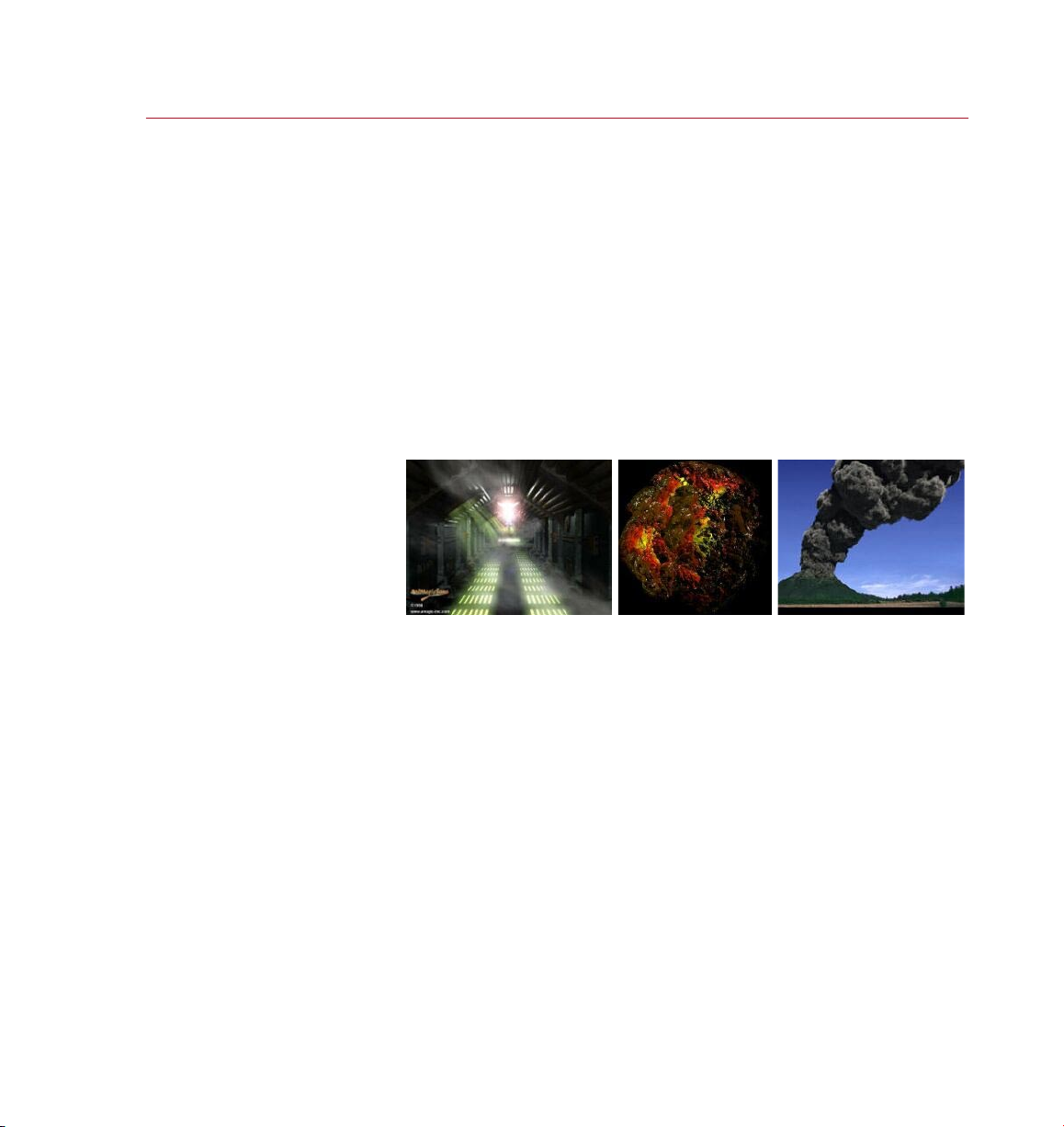
PYRO CLUST ER
INTRODUC TION 1
Introduction
From re to water, from hot rocks
to cool mists, PyroCluster puts
you in control of countless volume
effects that will add realism to
your stills and your animations.
An unli mited number of
spec tacul ar volum e effe cts
are pos sible w ith Py roClu ster,
including (but not limited to)
vapor y eff ects , solid r ock ef fect s
and pyroclastic effects.
PyroCluster is a module for CINEMA 4D that provides a powerful toolset for creating
such effects as realistic clouds, haze, re and smoke. With PyroCluster, in a single
module you have literally an unlimited number of volume effects.
PyroCluster effects are real 3D effects that will work with any CINEMA 4D -compatible
particle system. Spectacular PyroCluster effects can be combined with, for example,
the powerful animation features of the optional Thinking Particles module.
PyroCluster is fully compatible with the optional Thinking Par ticles module;
see your Thinking Particles manual for an example of how to combine these
two par ticle modules. For more information on Thinking Particles, please
contact your local MAXON dealer or visit ww w.maxon.net.
All effects are based on particles; each particle becomes a ‘puff’ and is rendered as a
real volumetric effect. A particle’s color can be determined by its age and a gradient
controller. This makes it easy, for example, to create white smoke at the beginning
and a dark oily smoke at the end of the particle’s life span.
To guarantee a awless integration into CINEMA 4D, many new programming
techniques have been developed. One of the amazing new technologies, developed
exclusively for the CINEMA 4D PyroCluster module, is the centralized atmospheric
tracer engine. This technology makes it possible to mix multiple volumetric effects in
a scene. Volume lights and PyroCluster effects will automatically combine correctly,
even casting volumetric shadows – indeed, PyroCluster supports shadow casting
with any light source.
Registration
Registering your PyroCluster module is extremely important. The serial number
included with your PyroCluster package is temporary and it will expire three months
after the module’s installation. To receive your nal serial number, you must register.
So please ll in and return the registration form at the earliest opportunity.
Registering your PyroCluster module will also entitle you to technical support via
telephone, fax and email. By checking the appropriate box on the registration form,
MAXON will keep you informed of the latest product information and updates.
You can also register online at register.maxon.net.
Page 10

2 INTRODUC TION
PYRO CLUST ER
Installation
To install PyroCluster, run the installation program and follow the on-screen
instructions. The installation program will create a P yroCluster folder in your
CINEMA 4D Modules folder. The installation program will place all the CINEMA 4D
PyroCluster les into this PyroCluster folder.
Training
Training is available for P yroCluster and other MAXON products. For details, please
contact MAXON or your local MAXON distributor.
Web Resources
Thousands of powerful resources are available on the web, including online tutorials,
discussion lists, tex tures, models, galleries and information on 3D books. You will
nd links to a rich selection of these sites at www.maxon.net.
One website that you may wish to bookmark is www.plugincafe.com, the home
of CINEMA 4D plugins. Here you will nd dozens of useful plugins, both free and
commercial. For plugin developers, there are resources, including the SDK, tutorials
and a free support forum. Lastly, there is the MAXON website itself, www.maxon.net.
In addition to the links mentioned above, it is from here that you can register your
MAXON product, download updates, send MAXON a suggestion, check out the
gallery, learn from online tutorials and much more.
Technical Support
Your local MAXON distributor will be delighted to assist you with your technical
queries for PyroCluster. You are also welcome to contact MAXON directly.
Please note that you will be entitled to technical support provided you have registered
your PyroCluster module (see Registration, above).
Page 11

1 Reference
Page 12

Page 13
PYRO CLUST ER
REFERENCE 5
Overview
Driven by a high quality,
volumetric render engine,
PyroCluster enables you to
produce truly spectacular
realistic effects.
Volumetric effects are among the most spectacular of all 3D effects, especially when
animated. PyroCluster can not only be used to create regular volumetric effects such
as smoke and haze, but it is also perfect for ery or solid liquid effects.
The name ‘PyroCluster’ is borrowed from a natural phenomenon called a pyroclastic
cloud. Pyroclastic clouds, a mixture of superheated gases and small dust particles,
are often the cause of an erupting volcano and they may end up killing more people
than the actual eruption. A seriously powerful phenomenon, and PyroCluster is a
seriously power ful addition to your 3D toolkit.
PyroCluster works in conjunction with particle systems by adding a procedural volume
around each particle. Particles can be generated using CINEMA 4D’s default particle
system, the optional Thinking Particles module or any other particle system that is
compatible, and the particles can be manipulated using any of the controls for that
system, including such forces as gravity, wind, friction and collision.
Page 14
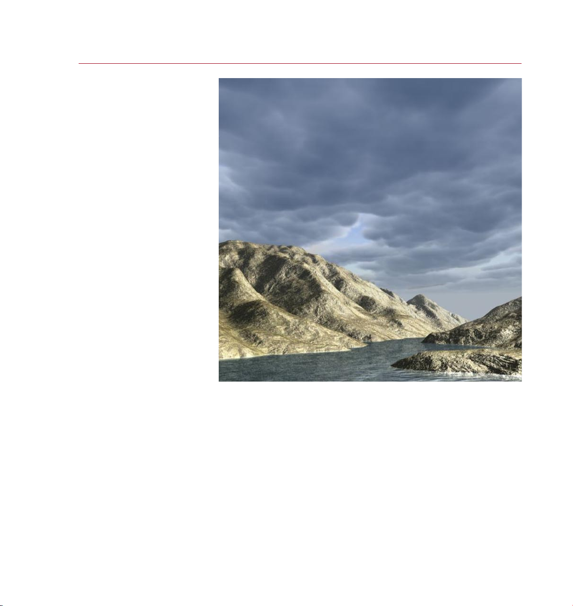
6 REFERENCE
PYRO CLUST ER
Many kin ds of gas eous
cloud e ffects are possib le.
PyroCluster employs a unique interface that utilizes gradients to control the effect.
Gradients control the color, age, scale animation and variation of each P yroCluster
volume. By simply sliding or editing color boxes you can change the PyroCluster effect
dramatically. Presets for re, smoke, clouds, steam and volcanic ash can be used as
is, or edited further to achieve the look you desire.
A realtime preview window displays the look of the PyroCluster effect as you make
changes, so you can get just the effect you want. What’s more, all of PyroCluster’s
parameters are accessible through XPresso, CINEMA 4D’s node editor, so you can use
sliders or other objects in the scene to adjust the P yroCluster effect.
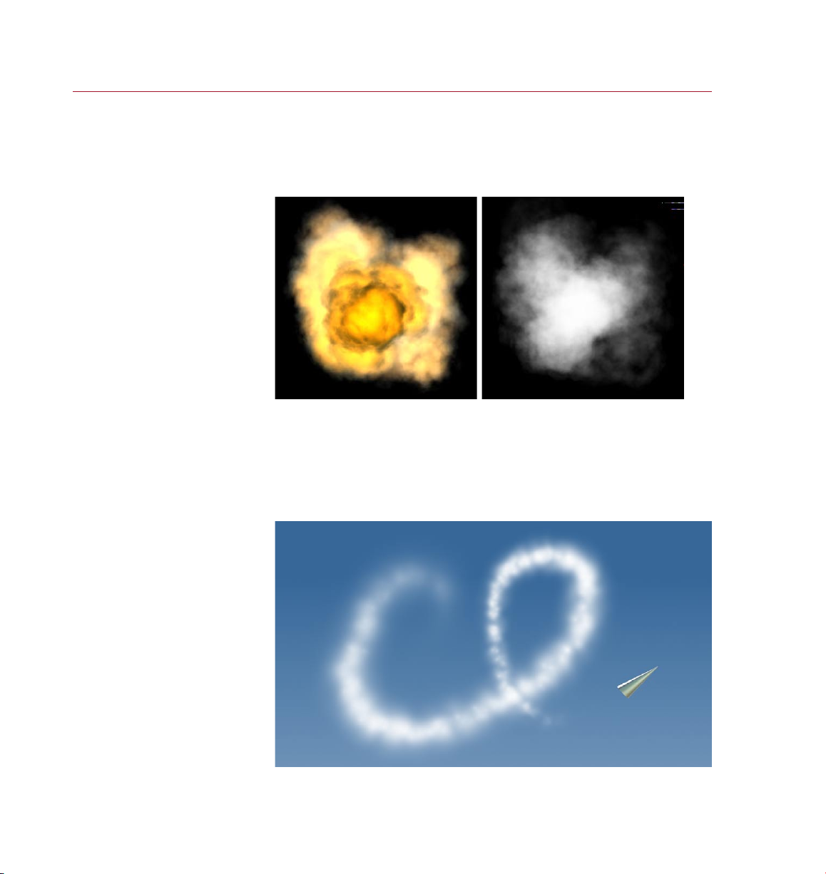
With this high degree of control, you can make ever ything from re and snow to
smoke trails look realistic and exciting.
Reali stic, a nimate d
vapor trails add
enorm ous impact
to a scen e.
Page 15
PYRO CLUST ER
REFERENCE 7
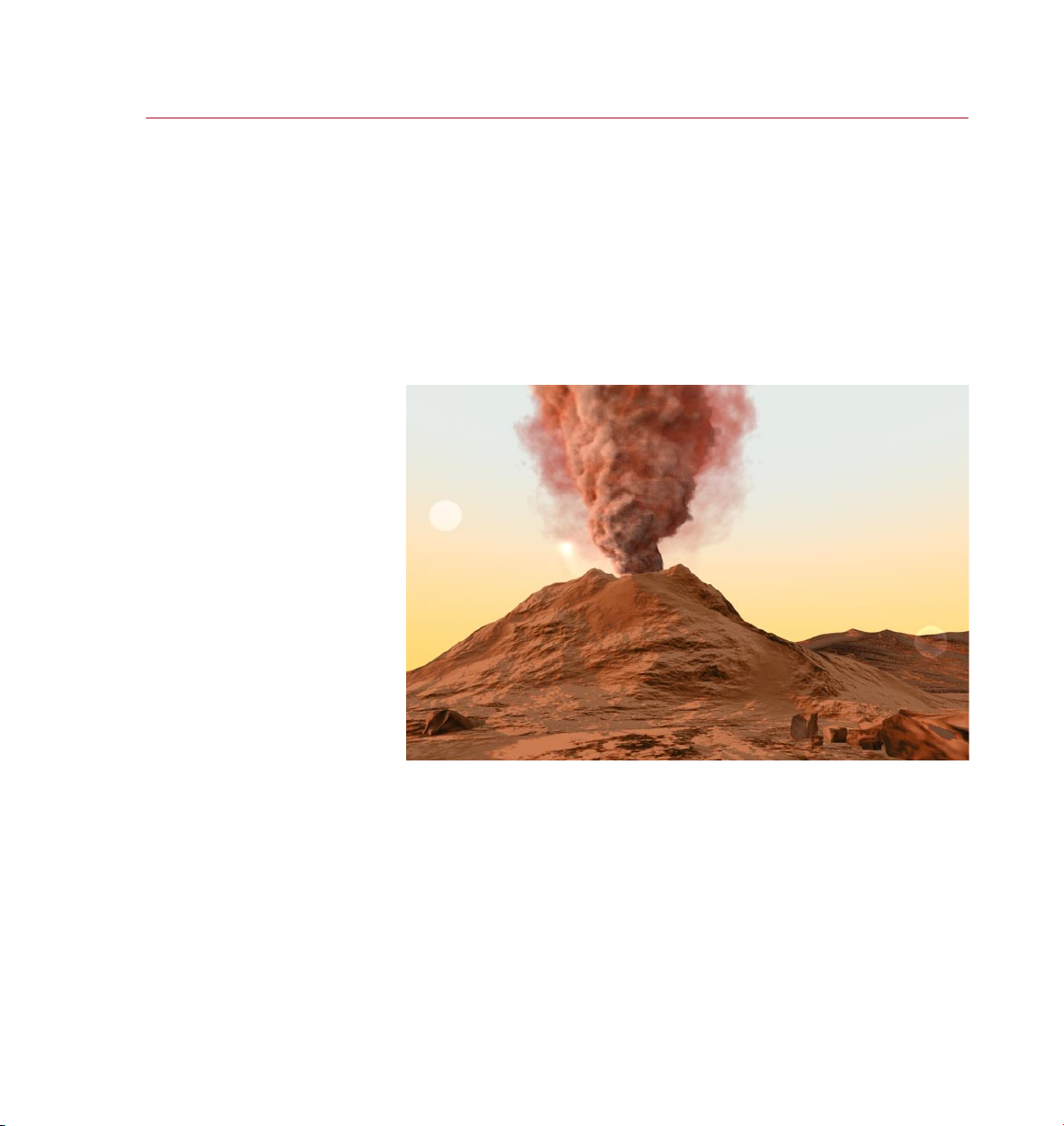
Thick , turbulent vol canic
cloud s are jus t one of
the Py roClu ster pr eset s.
Advanced optimization features in the PyroCluster Volume Tracer (the bit that
actually does the rendering) offer many ways to improve render speed and quality.
For example, PyroCluster provides two ways to create shadow maps for a single light
source. One light can affect self shadows in the volume differently from the shadow
that is thrown onto other objects by the cloud or volume effect. Imagine how much
render time you can save by using just a single light in a scene.
PyroCluster effects can be rendered in atmospheric mode so that they interact with the
objects and lighting in your 3D scene — or, when the PyroCluster effect doesn’t need
this level of interaction, it can instead be rendered much more quickly as a 2D post
effect and composited directly into your render. The variety of options provided help
you to maximize the impact of your imagery as well as minimize your render times.
In the real world, explosions, clouds and smoke interact with the objects around
them, and so can PyroCluster effects.
PyroCluster’s extensive options include control over the lighting and shadowing of
particles. The ef fect can cast and receive shadows, as well as shadow itself. You
can also activate illumination to brighten your scene with a ickering candle or a
massive reball. And if you’re using CINEMA 4D’s optional Advanced Render module,
PyroCluster’s volume and illumination are included in the radiosity calculation for
even more realistic lighting solutions.
Imagine what you could do with this amazing volumetric solution — with PyroCluster
the possibilities are literally endless.
Page 16
8 REFERENCE
PYRO CLUST ER
Creating a PyroCluster Effect
To get you started as quickly
as possible, here are the
essential steps to produce a
PyroCluster effect.
Assi gn just these two
Pyro Clust er ‘mate rials ’ and
you’re up a nd runn ing.
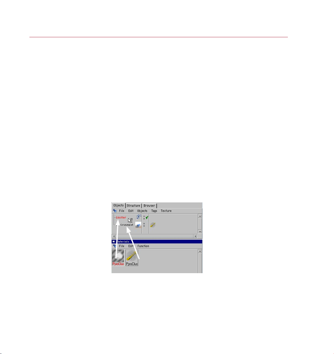
Setting up a PyroCluster effect is a simple process of making two special new materials
in the Material manager and then assigning those materials to the appropriate objects
in the Object manager.
- Choose Objects > Scene > Environment to create an Environment object.
- In the Material manager, choose File > PyroCluster > PyroCluster - VolumeTracer
to create a new Volume Tracer.
- Drag the Volume Tracer from the Material manager and drop it onto the
Environment object in the Object manager.
The Volume Tracer can be assigned to any object and it will control the rendering
of all PyroCluster effects encompassed by that object (see ‘Settings for the Volume
Tracer Material’ later in this chapter). Here we are assigning the Volume Tracer to
an Environment object and you will often do that because the Environment object
encompasses the entire scene.
- In the Material manager, choose File > PyroCluster > PyroCluster to create a
new PyroCluster shader.
- Assign the PyroCluster shader to the relevant particle system (drag it from the
Material manager and drop it onto the particle emitter in the Object manager).
PyroCluster works best with a total particle count of around 200–600. To
obtain a larger effect, instead of increasing the particle count you should
increase the size of the puffs and make them more dense. You need high
particle counts only for fast moving particle systems or when the particles
disperse into a large volume.
Once the materials are assigned, creating the desired effect is achieved by adjusting
various settings in the Material Editor or Attribute manager (see ‘Settings for the
PyroCluster shader’ later in this chapter).
Page 17
PYRO CLUST ER
REFERENCE 9
Smoky effe cts re quire m any
complex frac tal cal culations
to prod uce the ‘partic les’ that
make up the volume.
We have included many sample les and animations, and these can be found
in the Features/PyroCluster folder within the CINEMA 4D folder. You might
like to merge these into your own scenes and modify them to your needs. By
experimenting with these sample effects you can begin to understand how
to build your own effects from scratch.
The settings for the Volume Tracer, which is the part of PyroCluster that controls how
the effect will be rendered, can also be edited in the Attribute manager or Material
Editor (see ‘Settings for the Volume Tracer’ later in this chapter).
With the settings for the PyroCluster shader and the Volume Tracer completed, you
render a PyroCluster effect in the normal way, i.e. by selecting one of the regular
CINEMA 4D render options. A PyroCluster effect can be rendered either as a full
atmospheric effect or as a post effect according to the PyroCluster shader’s Render
Mode selected on the Globals page in the Attribute manager or Material Editor.
How are PyroCluster effects created?
To obtain fa ster render t imes tr y
incre asing t his valu e.
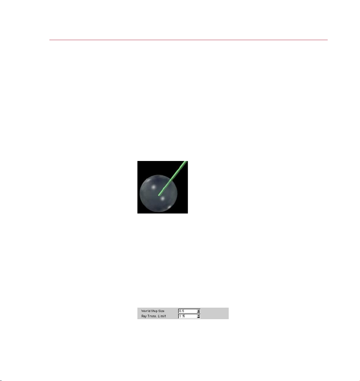
In the image above a single ray is illustrated cutting into a puff’s volume, taking
samples in order to produce realistic 3D volumetric effects. PyroCluster uses many of
these rays to create the full 3D volume effect. As the rays travel deep into the puff’s
volume, a fractal calculation is made at every relevant point to produce the correct
volume density. This is a number-intensive calculation and you can expect it to take
some time; volumetric effects simply cannot be calculated quickly — you might already
know this if you’ve used volumetric lights. A faster processor will always speed up
the rendering of PyroCluster’s effects.
Having said that, PyroCluster is built to be efcient and provides many powerful
features to help reduce render time. There are many ways to ne-tune your scenes;
one particularly useful one is found in the Volume Tracer settings. Changing just one
setting here, World Step Size, can save hours or even days of rendering time.
For as long as there is no unacceptable degradation in image quality, keep increasing
the World Step Size value.
Page 18

10 REFEREN CE
PYRO CLUST ER
To nd the optimum value for World Step Size we suggest using a manual subdivision
technique. Start with a number as high as you think is reasonable, let’s say 10. Perhaps
the image looks terrible, with no detail at all. So cut the value in half and, if the image
is still unacceptable, halve it again. When the image quality is acceptable, increase
World Step Size by half the value that you previously cut it by — so if a value of 5
produced a good image after 10, you would increase to 7.5. If the image is now poor
again, decrease to, say, 6.3, and so on.
With just a few test renders you will discover the optimum setting for the scene; you
may nd your scene now renders literally 100 times faster. No computer algorithm
can do this job better than you can, especially as only you can decide when the image
quality is acceptable.
You can cut render times even further by gradually turning up the Ray Trans. Limit
value once you have found the optimum World Step Size.
Page 19
PYRO CLUST ER
REFERENCE 11
Settings for
the Volume
Tracer Material
The PyroCluster Volume
Tracer is required for
rendering the PyroCluster
effects. Assign it to the
object within which you
want to use PyroCluster.
Create a Pyro Cluster
VolumeTrace r ‘mater ial’ in the
Mater ial mana ger and selec t it
to see it s globa l settings in th e
Attri bute man ager.
The Volume Tracer is the part of PyroCluster that controls how the effect will be
rendered and where it will be rendered. The settings you make for the Volume Tracer
will greatly affect the render quality and render speed for the effect.
There are no hard-and-fast rules for these settings, it will be different for every scene
and will completely depend upon what is being rendered, so some experimentation
will always be required to nd the optimum settings for a Volume Tracer. See ‘How
are PyroCluster effects created?’ earlier in this chapter for further advice.
The Volume Tracer is a special ‘material’ and is created in a similar way to other
materials in CINEMA 4D.
To create a new Volume Tracer material:
- In the Material manager, choose File > PyroCluster - VolumeTracer.
Remember, to create PyroCluster effects you need to add at least two
materials: VolumeTracer and PyroCluster. See ‘Creating a PyroCluster Effect’
earlier in this chapter.
You may have more than one Volume Tracer in a scene. Each Volume Tracer controls the
rendering of all PyroCluster effects that are encompassed by the object to which the
Volume Tracer has been assigned. Each Volume Tracer may have its own settings.
You can edit the Volume Tracer’s settings in the Attribute manager or in the Material
Editor.
The Volume Tracer settings are ‘global’ insofar that they affect the rendering
of all PyroCluster puffs that are encompassed by the object to which the
Volume Tracer is assigned.
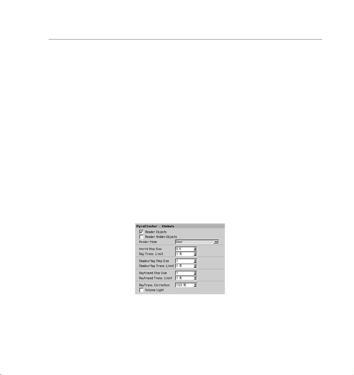
Render Objects, Render Hidden Objects
To render PyroCluster effects in a scene, enable Render Objects. To render any hidden
PyroCluster particle systems, enable the Render Hidden Objects option.
Page 20

12 REFERENCE
PYRO CLUST ER
Render Mode
Here you can choose from various preset render modes. The main differences between
these modes are their render quality and how long they take to render. In order of
best render quality (and longest render time) rst, these are:
• Crispy
• Crispy- Gas
• Hazy
The following mode:
• User
allows you to set your own render mode using various parameters that will no longer
be ghosted including World Step Size and Ray Trans Limit.
Step Size settings
The Step Size settings are available only when Render Mode is set to User.
See also ‘How are PyroCluster effects created?’ earlier in this chapter.
To improve rendering time for volumetric PyroCluster effects you should set the step
sizes to reasonable values.
What is a reasonable step size? This question leads us to a problem that is common
to all volumetric fractals (a smoke cloud is a really large 3D fractal) – which is that you
can never tell in advance exactly how they will look when rendered. Many parameters
depend on each other and different combinations can have a dramatic impact on the
look and the render time of the nal effect.
The step sizes control how accurately the 3D space is sliced to nd PyroCluster volumes
(puffs) in the scene. As a rule of thumb, lower values (more slices) will usually result
in longer rendering times. If you feel that your scene is taking too long to render, try
adjusting these values rst.
Suppose you’ve created a scene with some clouds in the sky. You have chosen really
large volumes to create the 3D clouds (i.e. a large Radius value on the Shape page
for the PyroCluster shader). Each single puff has a radius of 2000.
If you leave the World Step Size at the default value of 0.5 you will wait forever to
nish rendering the scene, as too many samples are taken over the large volume.
In this case you could increase the step size values up to 60 without sacricing the
render quality.
If, on the other hand, you choose a small Radius value, say 10, and you still use step
sizes of 60 the render will be ugly, with single-color spheres only. This is because,
with a step size of 60, nearly all the small PyroCluster volumes would be missed in
the render. It will render very quickly, though!
Page 21
PYRO CLUST ER
REFERENCE 13
RayTrans. Co rrec tion en abled
(lef t) and disable d (right).
Trans. Limit settings
The Trans. Limit settings are available only when Render Mode is set to User.
See also ‘How are PyroCluster effects created?’ earlier in this chapter.
These parameters of fer another way to speed up render times. They determine the
cut-off value for the Volume Tracer engine. Usually the volume is traced deeply until
the transparency of a point is 0, i.e. it is 100% opaque. However, most of the time
you won’t see any change in the result if the Volume Tracer stops some way before
this 100% opaque cut-off value. Numbers between 1% and 10% are normally ne
and help greatly in speeding up render time.
RayTrans. Correction
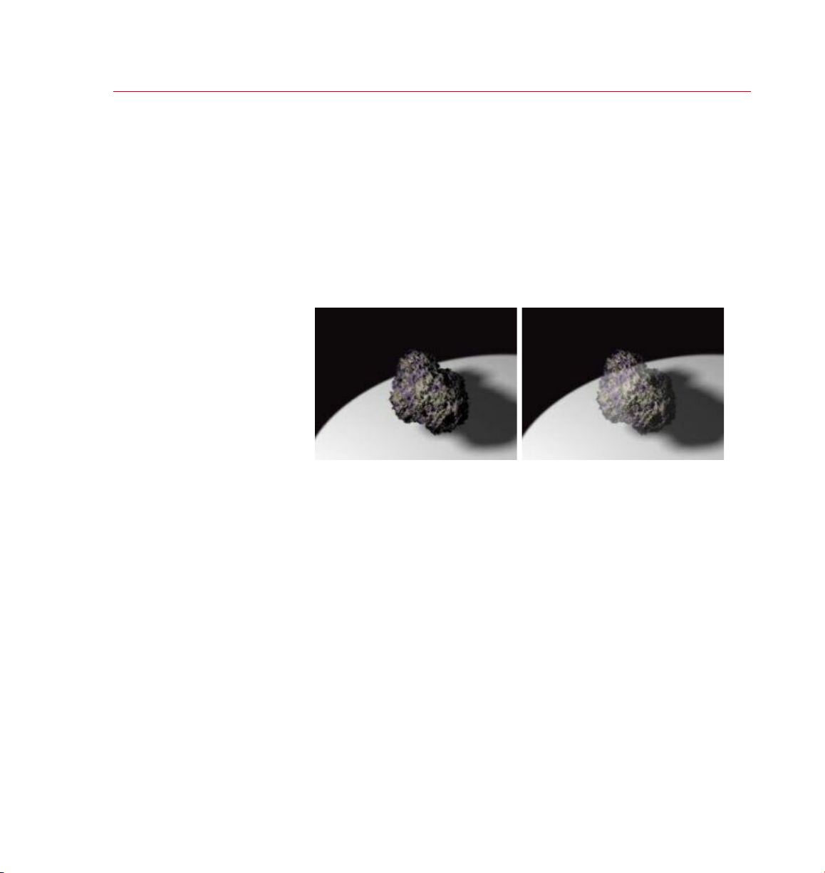
As explained in the previous section, if you increase the transparency cut-off value
used by the Volume Tracer (the Ray Trans. Limit value) you gain render speed. However,
some artefacts may appear when using Ray Trans. Limit to the extreme. In these
cases you should enable the RayTrans. Correction, which will attempt to correct these
problems — see the images above.
Disabling RayTrans. Correction means that the volume effects will render more
transparently as you increase the Ray Trans. Limit This happens because the rays
traveling into the volume are stopped before they become 100% opaque. PyroCluster
uses the transparency value as it is set in the Limit box. To prevent this, enable the
RayTrans. Correction parameter.
Page 22
14 REFEREN CE
PYRO CLUST ER
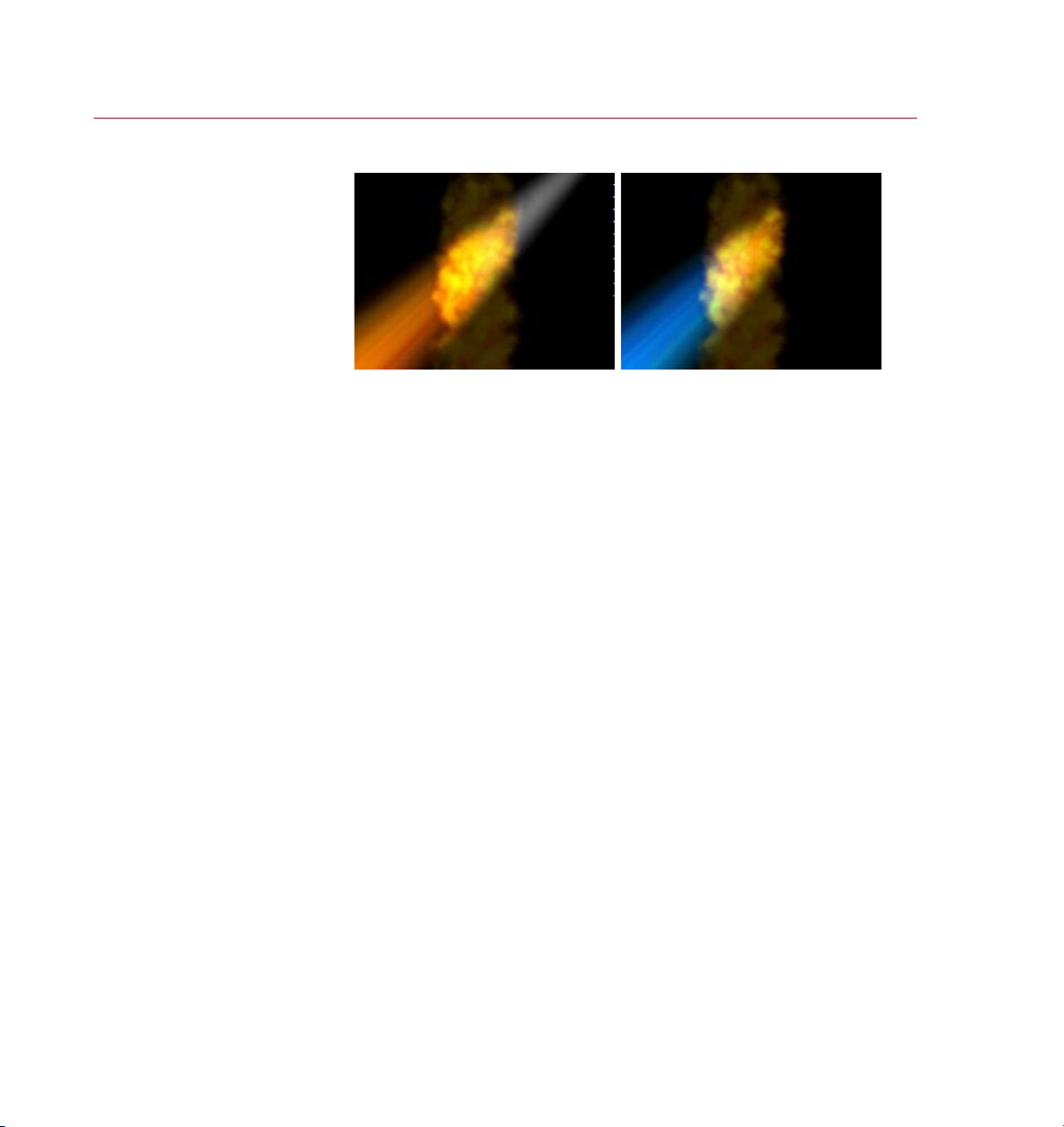
Volume li ght with Shadow Color
Filter turned on (lef t) and with
an inver ted li ght effect (right) .
Volume Light
By default, PyroCluster supports volume light effects. You may use any CINEMA 4D
light and effect to illuminate PyroCluster atmospherics, including Inverse Volumetric
lights.
To obtain colored volume light shadows, enable the Shadow Color Filter option on
the Shadow page for PyroCluster.
Page 23
PYRO CLUST ER
REFERENCE 15
Gradients
Understanding how the
gradients work is key to
getting the most out of
PyroCluster.
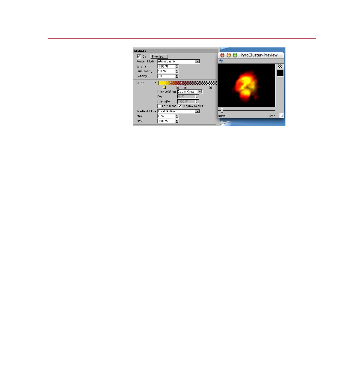
Certain parts of PyroCluster, such as age and distance effects, can be controlled via
gradients; an example of a gradient can be seen to the right of Color, above. Gradients
work the same way in all par ts of PyroCluster.
Using gradients
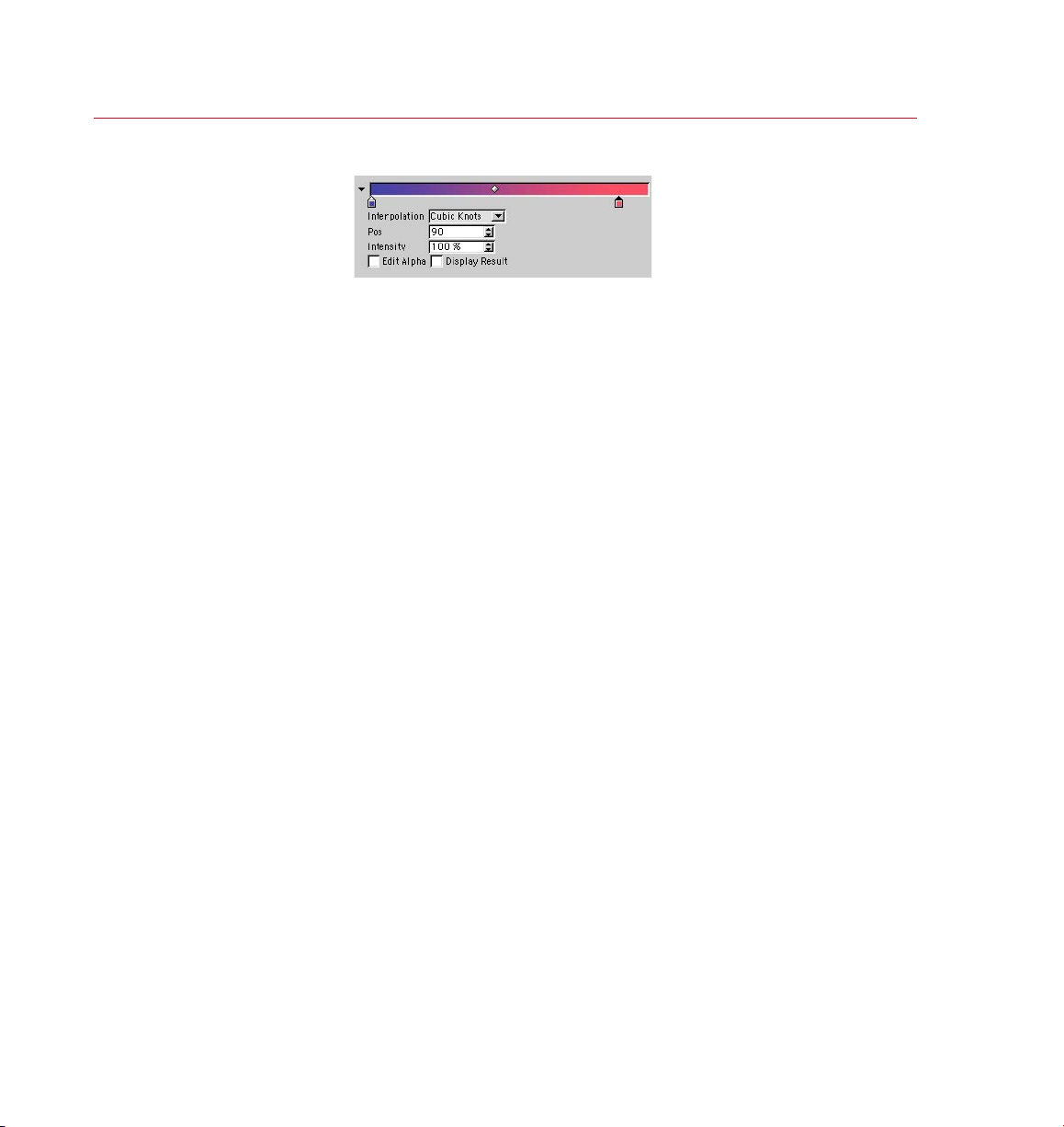
The small pointed squares underneath the gradient are called ‘knots’. Each knot ties
a color to the gradient at that position. Between the knots, in the gradient itself, you
will often see small diamond shapes. These are called ‘bias handles’ and they control
how the color changes between two knots.
To add a knot:
- Click in the empty space below the gradient.
To change the color that the knot is tying to the gradient :
- Double -click on the knot and a color picker dialog will open.
To remove a knot:
- Drag the knot away from the gradient.
To move a knot or bias handle to a different position:
- Drag the knot or bias handle left or right and drop it at its new position;
- or select the knot or bias handle and enter a value into the Pos box.
To change the way color is interpolated between the knots and bias handles:
- Choose from the Interpolation menu.
To change the strength of a knot:
- Select the knot and enter a value into the Intensity box.
Page 24
16 REFEREN CE
PYRO CLUST ER
To open and c lose th e
gradie nt opti ons, cl ick the
small triangl e that is on the
left o f the grad ient.
The gradient and its options
Interpolation
Cubic Knots
Interpolates between the knots and bias handles using CatmullRom interpolation.
This method is ideal when using a large number of knots. Drag a bias handle left
or right to adjust the bias of the interpolation.
Cubic Bias
Uses a Bézier interpolation algorithm to interpolate between the knots and bias handles.
This method is a good choice for accurate control and for when using just a few knots.
Drag a bias handle left or right to adjust the bias of the interpolation.
Smooth Knot
Uses a SmoothStep function to interpolate between the knots and bias handles.
Drag a bias handle left or right to adjust the bias of the interpolation.
Linear Knot
Uses a BoxStep function to interpolate between the knots and bias handles. Drag
a bias handle left or right to adjust the bias of the interpolation.
Linear
A simple linear interpolation between the knots. No bias handles are available.
Exponent Up, Exponent Down
Exponential falloff/growth between the knots.
None
No interpolation, producing abrupt changes between the colors.
Position
This is the position of the selected knot or bias handle on the gradient. To move a
selected knot or bias handle, either type a value into the input box or use the up/down
arrows to the right of the input box.
Page 25

PYRO CLUST ER
REFERENCE 17
The Edit Alpha and
Displ ay Resul t optio ns
chang e the grad ient
display accordingly.
Intensity
The measurement of intensity for the selected color knot.
Edit Alpha, Display Result
A few effects can have transparency added via an alpha channel gradient. To edit
the alpha channel gradient, enable the Edit Alpha option; a grayscale gradient will
replace the current gradient. Where the gradient is white the dened color will be fully
opaque whereas black on the gradient indicates full transparency. To see a preview
of the transparency in the gradient, enable Display Result.
Enable the Edit Alpha option to show and modify the gradient’s corresponding alpha
channel, which determines the transparency over the length of the gradient.
Enabling the Display Result option displays the gradient taking the alpha channel into
account. This gradient is the one that will actually be used in the render.
The context menu for gradients
To open this menu Right-click (Windows) or Command-click (Mac OS) the gradient.
Invert Knots
Reverses the gradient.
Double Knots
The amount of knots is doubled.
Reset
The gradient will change to solid white.
Working with gradients
There are so many parameters that interact with one another that the number of
combinations for a PyroCluster effect are nearly endless. Think carefully about the
effect you want to create. Try to break it down into issues of color and time.
Take a amethrower effect; what does a real one look like? Close to the amethrower
nozzle the ame is a hot, transparent white and blue, while the fur ther away the
ame is from the nozzle, the darker, redder and more opaque it becomes.
Page 26
18 REFEREN CE
PYRO CLUST ER
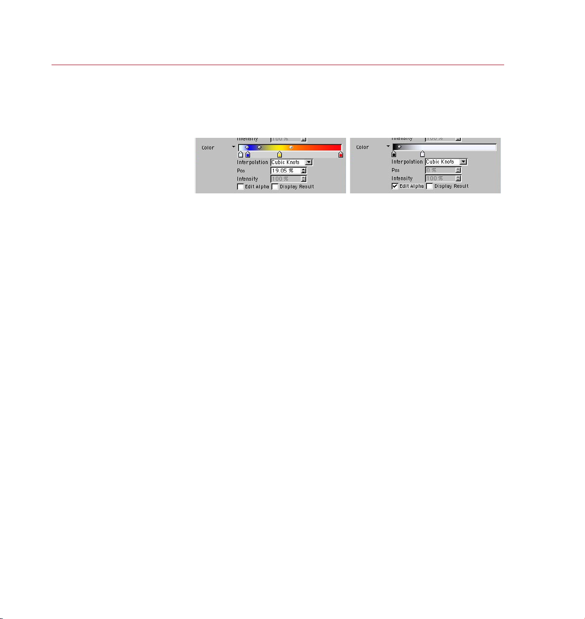
Figure 1 (left): Setting t he
color of the ame thrower.
Figure 2 (right ): Set ting th e
transp arency of the ame.
Each amethrower particle ying away from the emitter (i.e. the nozzle), has an
age — it was born at some time, it will die at some time. So we’ll use the Age page
to dene the colors of the ame over time.
Setting colors
Time is indicated in the gradient as particle birth on the left and particle death on the
right. So, the white and blue ame that should appear close to the nozzle (shortly after
the particle birth) should be set on the left-hand side of the Age gradient and the darker,
yellow-red colors that appear further away from the nozzle (getting closer and closer
to particle death) are set on the right-hand side of the Age gradient (Figure 1).
How do you make the hot white and blue ame be transparent at the beginning?
Easy. There is a separate gradient (enable Edit Alpha) that controls transparency over
time, via a grayscale Alpha gradient (Figure 2).
Particle settings
PyroCluster effects are always applied to particle systems. Each valid particle system
has its own settings for lifetime, size, rotation and other variables. PyroCluster uses
these settings to create its smoke, re or cloud effects.
You do not need to worr y about the size or shape of the particles generated by the
particle system; PyroCluster does not use size or shape information at all, although
it does need to know the particles’ positions. So you’ll want to set the size of the
particles to 0 in most cases, or hide the particle system so that you don’t see hard
nuggets at the center of each PyroCluster puff. The size of any given cloud or smoke
puff is directly controlled by PyroCluster.
The power of life and death
Animating the size of the cloud or smoke is a straightforward task. On the Globals page
of the PyroCluster shader, you can set the radius of the particle when it’s born — this
will be the radius of the smoke puff rendered in place of every particle at the start
of its life. On the Age page you can then set the radius of the particle when it dies.
PyroCluster will interpolate between these values (birth and death radius) over the
lifetime of the particle.
The speed or depth of this interpolation is controlled by the Color Mix gradient that
is dened on the Age page of the PyroCluster shader.
Page 27

PYRO CLUST ER
REFERENCE 19
An exa mple of the Color
gradie nt on the A ge page .
Animating colors
To control the particle radius by age (so that older particles grow larger, say) is a
straightforward concept, but what about changing the color of each particle over
time? At rst glance, the color gradients in P yroCluster can be a little daunting, so
we’ll give an overview here. See the relevant descriptions of the various options for
more detail.
The Color gradient on the Globals page controls the par ticle color and the Color
gradient on the Age page controls the color change over the particle’s lifetime. So,
when Age effects are enabled, the color of the particle at any time is taken from the
Age Color gradient and mixed with the color dened by the Color gradient on the
Globals page. The color mix between these two colors is controlled by the Color Mix
gradient on the Age page.
Let’s take a look at an example Age Color gradient, below.
Frame 0 Fra me 50 Fram e 100
This Age Color gradient assumes a particle system with a particle life of 100 frames
and with all of the particles born at frame zero. After 100 frames the particles die.
If, on the other hand, the par ticle life had been set to 60 the right-hand edge of the
gradient would dene the particle color at frame 60.
Usually, particle life varies for each par ticle (set using a ‘lifetime variation’
parameter in the emitter) which is why you can’t always know the exact
frame numbers in a gradient—they change with every particle.
In the example above, the newly-born particle is colored yellow at frame 0, then
between frames 0 and 50 it gradually becomes red; nally, at frame 100, the particle
dies with a blue color. This example assumes a changing Age Color with no global
color mixed in. The color gradient you set on the Globals page of the PyroCluster
shader acts as a base color that can be mixed with the Age Color.
The mixture between the Globals Color and the color calculated as the particle ages
is controlled by the Color Mix gradient on the Age page. A plain white in the Color
Mix gradient will not mix and of the global color at that particular position on the
gradient (i.e. at that age of the puff or particle). Increasing shades of gray will mix in
more of the Globals Color. You can easily use the Mix gradient to make clouds icker
or pulse like burning oil.
Page 28
20 REFER ENCE
PYRO CLUST ER
The gradient
controls the
base color of the
particle cl oud.
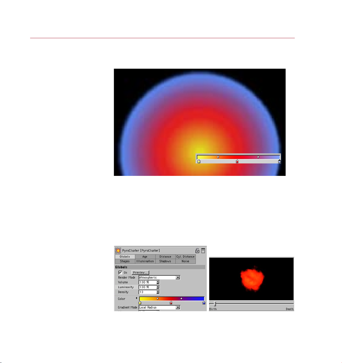
Here is an example of using the color mix feature. First, let’s assume that you have
dened a gradient for Color on the Globals page, as shown below. So each puff
consists of a yellow core, turning through red to blue at its edge.
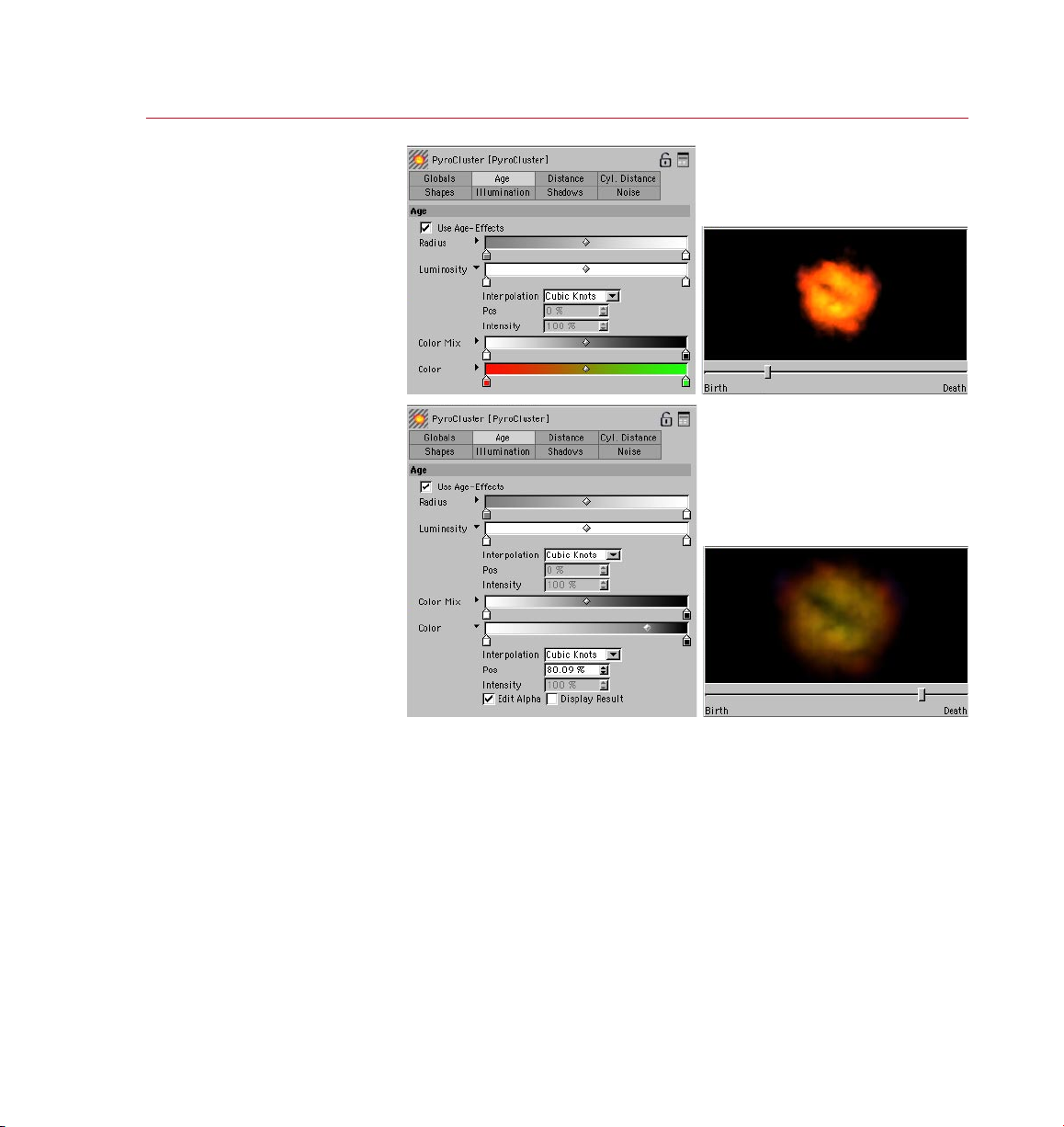
You’ve then created a gradient for Color on the Age page that looks like the gradient
in the second picture below: red at the particle’s birth, turning green as the particle
dies.
The following results would be rendered for a Color Mix gradient that started at
white, turned gray in the middle and ended at black. Red is mixed in at birth, turning
the whole particle red. As the particle ages, dark yellow is mixed in, allowing the
yellow core to show through. Then darker colors predominate as the particle dies.
The particle is also becoming more transparent as it dies out because of the Alpha
set on the Age page.
The Col or gradi ent on th e
Globals page, set up to gi ve
each pa rtic le a yell ow core,
sprea ding ou t to red an d then
blue at its edge s; the gradien t
has three knot s (yellow, red,
blue fr om lef t to right ). No Ag e
effe ct has yet been added.
Page 29
PYRO CLUST ER
REFERENCE 21
Mix in so me red, t urning to
green over time, with mixing
mainly happening towa rds
the end o f the par ticle’s life.
The Age p age’s Color grad ient
has two k nots (red at the left ,
green at the rig ht) and the
Color M ix gradi ent goes from
Finall y, add some transp arenc y
as the particle dies by d enin g,
on the Ag e page, an alpha
gradie nt for th e Color that goe s
from wh ite to bla ck. Enable Edit
Alpha t o edit th e alpha gradien t.
white to b lack.
Page 30
22 REFER ENCE
PYRO CLUST ER
Settings
for the
PyroCluster
Shader
You create a PyroCluster
shader in the Material
manager. You can edit the
shaders settings in the
Attribute manager or in
the Material Editor.
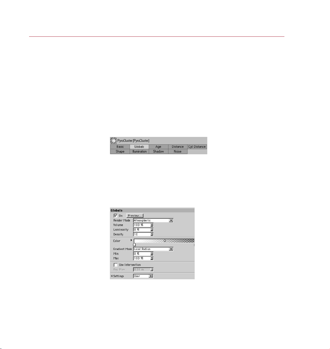
The pag es in the Attrib ute
manager for the Pyro Cluster
This page contains general
sett ings for the selected
Pyro Clust er shad er.
shade r.
You can use all of PyroCluster’s effects together. However the result may not
always be what you would expect. Depending on the settings, for example,
the Distance effects may carry more weight than the Age effects.
Keep in mind that some parameters also affect the fractal look of the
rendered atmospheric effect. Always be prepared to experiment!
PyroCluster is controlled almost entirely via its property pages in the CINEMA 4D
Attribute manager or Material Editor. From these you can dene a shape for your
PyroCluster particles, choose the type of effect (such as gaseous or re), determine
the render mode, change effects over the lifetime of the particles and much more.
Here you’ll nd many parameters that interact with one another to produce the nal
effect. A oating Preview window enables you to tweak any parameter and see a
preview of its effect immediately (see ‘Preview’ below).
Basic Properties page
On this page you can rename the material.
Globals page
The settings on the Globals page control general parameters which describe the basic
proper ties of a P yroCluster shader.
On
The On/Off switch is especially useful when you are ne-tuning a scene. It allows you
to turn the PyroCluster shader on and off for the selected material.
Page 31
PYRO CLUST ER
REFERENCE 23
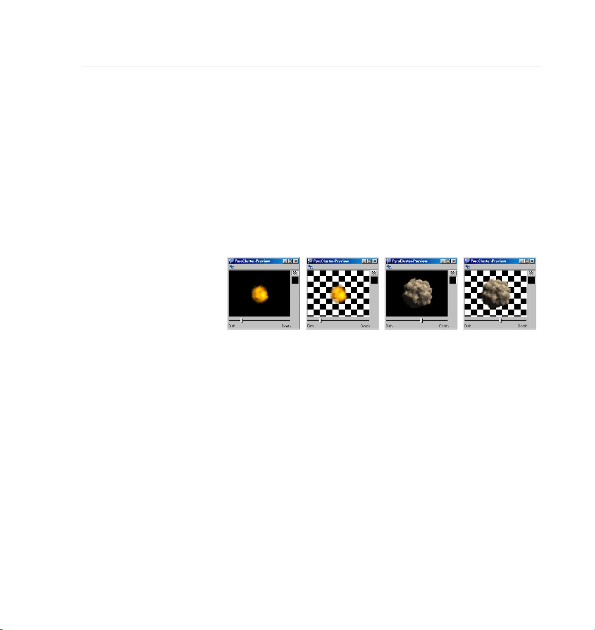
Some ex ample s of usin g the
Pyro Clust er prev iew, illustrat ing the
use of the background opt ion and
the age s lider. Changes to s etti ngs
will be s hown ins tantl y in the
previ ew, which uses shadow cas ting
lights to repr esent t he eff ects a s
accura tely as p ossible.
Render Mode
By using PyroCluster as a post effect (VideoPost) you can often cut render times
dramatically. When VideoPost is selected, a simplied rendering process is used,
which among other things handles fractals differently. This means that you will get
a different result when using VideoPost than you would with Atmospheric mode.
For better and faster results with VideoPost, turn off particle shadows using the
relevant options on the Shadow page. If you leave particle shadows on, there may
be little or no increase in render speed. Note that, in general, VideoPost rendering is
faster only if you are using a large number of particles.
The limitations of the VideoPost mode are that fractals look different, particles cannot
be seen in reections or behind transparent objects and Flat Radius mode is always
used, regardless of the Gradient Mode selected.
Preview
Once you are familiar with PyroCluster you’ll nd that it is not always easy to predict
how the various options will affect the nal result. Fractal volume calculation is highly
complex and the interdependencies are limitless; the color of one point in the volume
may be affected by hundreds or even thousands of other points in the volume.
PyroCluster is simulating natural phenomena and, as in nature, things like clouds
and uid movements are often chaotic and unpredictable. It would all be too hard
if there wasn’t a hint as to how P yroCluster effects will render; this is where the
PyroCluster preview comes in.
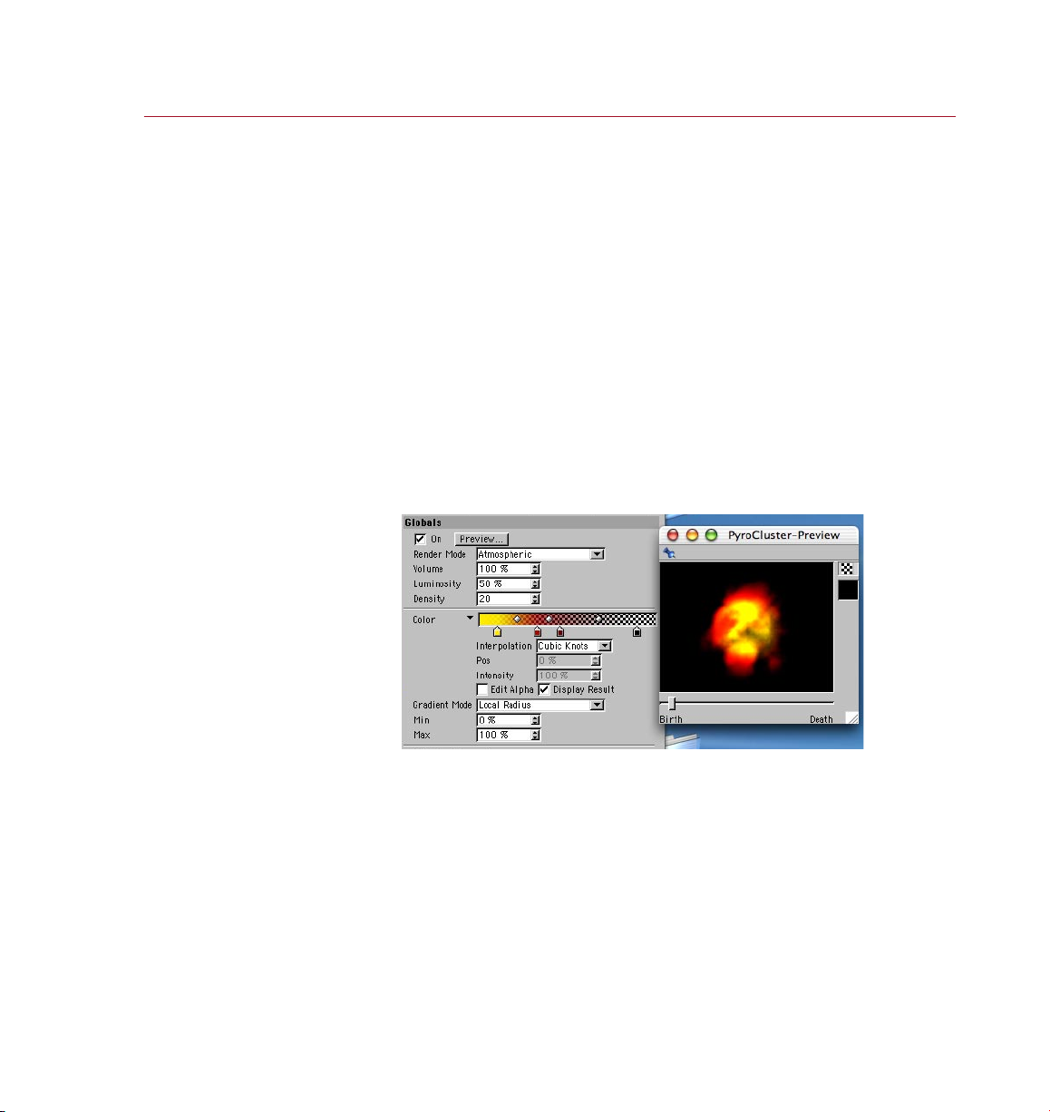
Enable the oating PyroCluster Preview window by clicking the Preview button on the
Globals page. This window will render a single puff using all settings. A live connection
between the settings and the preview means that any change to the settings will
automatically be reected in the preview. The preview window uses shadow casting
lights to render the puff as accurately as possible.
The PyroCluster preview has a number of options. You can toggle between a checkered
pattern background (with a transparent puff) and a solid, colored background by clicking
the checkered icon. You can change the color of the solid background by clicking on the
icon beneath the checkered icon. By dragging the slider at the bottom of the display,
you can update the display to show how the puff changes over its lifetime.
Page 32
24 REFER ENCE
PYRO CLUST ER
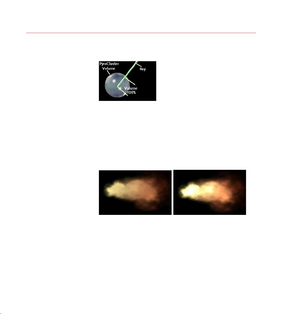
The Volum e value controls how
accura tely a ray is sub-sampled
within the PyroCluster vol ume.
Parti cles with Lumi nosit y set to
0% (le ft) and 100% (ri ght).
Volume
When using high World Step Size values, keep Volume at its default value of
100%
Volume controls how accurately a ray is sub-sampled in the PyroCluster volume; it
determines how far a ray penetrates into the volume and thus how many points are
sampled. A Volume of 50% would consider only half of the points in a volume when
creating the fractal noise. Lower values for Volume result in a faster calculation but
give an uglier, more blocky look to the smoke or cloud ef fect. Volume is one of the
most critical parameters in PyroCluster; it has a great impact on the look of the effect
and the render speed.
Luminosity
When, and how strongly, this additive calculation should occur is set using
the Luminosity gradients on the other pages of the PyroCluster settings.
Usually PyroCluster uses a weighted calculation algorithm to add the atmospheric
effects to the scene. The particular calculation used means that, in general, dense
clouds are rendered darker and more opaque than think clouds.
This Luminosity setting gives you control over the amount of additive pixel calculation,
expressed as a percentage of the total effect. This is the opposite of weighted pixel
blending because, in this case, as you increase the Luminosity value more particles
in an area result in a brighter overall appearance.
As you increase the value to 100%, Luminosity smoothly turns the calculation into
an additive pixel color blend; pixel intensities will be added and you will get bright
areas instead of dark ones in the cloud.
Page 33
PYRO CLUST ER
REFERENCE 25
The Col or gradi ent on th e
Globals page control s the col or
of the puffs.
Density
To obtain dark smoke effects, increase this value.
This value controls the overall transparency of the atmospheric ef fect. A value of 0
means that every single puff will be 100% transparent. Higher values will make the
volumetric effect more dense.
Keep in mind that low density values may have a huge impact on render time. The
puff’s density is calculated according to several aspects of the effect. Each particle
in the particle system generates a puff and each puff adds to the opacity of the
overall ef fect.
You can imagine the Density value as a global transparency controller for the puffs.
However, keep in mind that when you have just 100 particles with a high density, say
50%, you may well be able to see through this cloud. Increasing the particle count,
while keeping them in the same-sized volume, would result in a denser cloud.
Color
For details on using gradients, look up ‘Using gradients’ in the index.
The Color gradient controls the color of the puf f. From left to right, the gradient
represents the inside to the outside of the puff. This gradient provides the base colors
for all calculations and must therefore be created and edited with some thought.
Page 34
26 REFERENCE
PYRO CLUST ER
Parti cles te nd to loo k at in Fla t
Radius mode, but they ar e fast
to rend er.
Gradient Mode
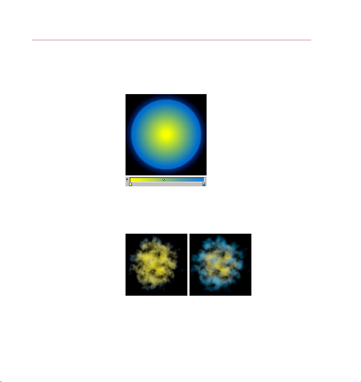
PyroCluster generally renders puffs based on the values in a color gradient. The color
to the left of the gradient is used in the center of the puff while the color to the right
is used at the outer edges.
Flat Radius
Flat Radius mode uses a trick to render the color gradient into the volume ef fect.
It’s not a true 3D gradient effect; rather, the gradient is drawn planar, perpendicular
to the camera’s view point. So use this option when you want faster renders, while
sacricing some image quality.
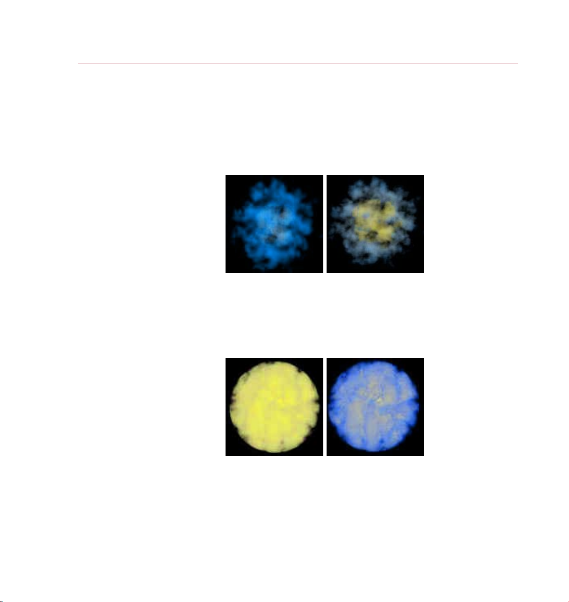
Local R adius g radients (using
the sam e gradie nt as in th e
Flat Radius example ab ove) with
Max set to 100 (lef t) and 50
(right). Note that the re is more
blue on the outer edges o f the
puff to the righ t because blue i s
used as t he puff color from 50%
of the rad ius to its full val ue.
Local Radius, Min, Max
Local Radius mode always applies the color gradient within the volume of the puff,
from the center to the surface of each puff. The color to the left of the gradient is
used for the center of the puff while the color on the right is used at the edges.
Page 35
PYRO CLUST ER
REFERENCE 27
Again using the s ame gra dient
as in the Fl at Radius exam ple
above an d a puff ra dius of 50,
here ar e two ex ample s of usin g
World Ra dius gra dient s with Max
set to 10 (le ft) an d 25 (right).
It makes no difference how large the puff grows, since the gradient is always adjusted
to t, a process known as ‘normalization’. You can change the normalization of the
gradient using the Min and Max values. Min represents the center area (0 is the
actual center) and Max represents the outer edge of the puff (100% is equivalent
to the radius of the puff). For example, a Max value of 80% means that the righthand side of the gradient color will be used to draw the puff when the distance
from the center is greater than 80% of the radius.
World Radius, Min, Max
World Radius mode uses a non-normalized color gradient and the Min and Max
values represent the radius measured in World coordinates. For example, suppose
the puffs have a radius of 50, the Max value is set to 25 and the color gradient is
yellow to blue: only the right-hand side color of the gradient (blue, in this case) will
be used to draw the puffs at distances more than 25 units from the center.
Density gradients with Ma x set
to 200 (left) and 80 (right), ag ain
using the gradient de ned in th e
Flat Radius example ab ove.
Density, Min, Max
Use the Density mode to draw the puffs based on the individual density values
of each point in the volume. The left-hand color in the color gradient is used for
areas of minimum (Min) density; the right-hand color of the gradient is used for
the areas of maximum (Max) density.
Page 36
28 REFER ENCE
PYRO CLUST ER
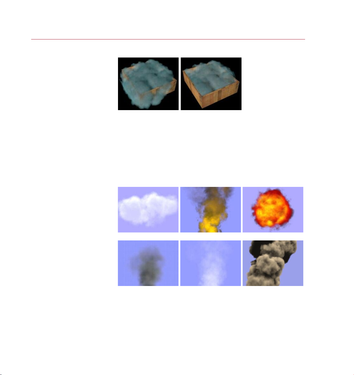
A woode n box lle d
with sm oke, with Use
Inter sect ion disabled ( left )
and ena bled (r ight) . The
enabl ed opti on keeps the
smoke in the box.
Six of the most commonly u sed
effe cts ar e availa ble as pr esets
on the Se ttings drop -down list.
Use Intersection, Ray Bias
Intersection tests are normally used to detect collisions in dynamic simulations.
However, intersection testing also helps to constrain gas or smoke, so enable this
option if you want to, for example, send a gas stream through a pipe. As you might
expect, intersections can take quite some time to calculate for gaseous objects and
a fast processor is recommended.
The Ray Bias value enables you to move the intersection point along the intersection
ray to ne-tune the result. A value of 0 represents the originally calculated point of
intersection; higher values will move the point away from there.
Settings
Cloud. Fire. Fireb all.
Smoke. Steam. Volcano.
Here you’ll nd six common set-ups for PyroCluster; select one of these presets and
ne-tune it to create the effect you’re looking for. The User entry will be automatically
selected when you edit a preset.
Page 37
PYRO CLUST ER
REFERENCE 29
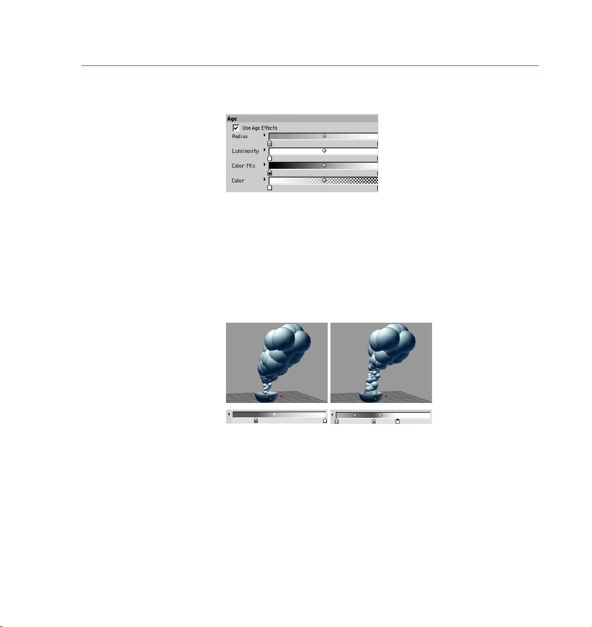
On this page you can enable and
disab le age ef fects and adjust
the animation p roper ties of
various attr ibutes.
In the Ag e Radius gradie nt,
white creates the radi us set on
the Shape page, while a bl ack
or a dark color creates a zero or
small vo lume radius respectively.
So, on the l eft, particles s tart
small and grow evenly ove r their
lifetime whil e, on the r ight, t he
particles a re larg er to start with,
shrink a littl e and the n grow to
their f ull size .
Age page
For details on using gradients, look up ‘Using gradients’ in the index.
With these settings, you can have puffs change their color, radius and luminosity
depending on how far away they are from the emitter. This is useful for effects where
the color, shape and luminosity changes over distance, such as the ames of rocket
boosters, for example.
Use Age Effects
Enable this option to switch on the age effects.
Radius
For details on using gradients, look up ‘Using gradients’ in the index.
The Radius gradient controls the puff’s radius over the particle’s lifetime; each
grayscale represents a radius value.
On the Shape page you can set the basic volume radius for the selected PyroCluster
material; without any other effects turned on, PyroCluster will use this radius to render
the cloud or smoke effects. However, if you enable Age Effects, it’s different.
A plain white color in the Age Radius gradient represents the radius dened on the
Shape page and a plain black color represents a radius of 0 (i.e. a dot). The left and
right edges of the Age Radius gradient correspond to the time of the particle’s birth
and death respectively.
Page 38
30 REFER ENCE
PYRO CLUST ER
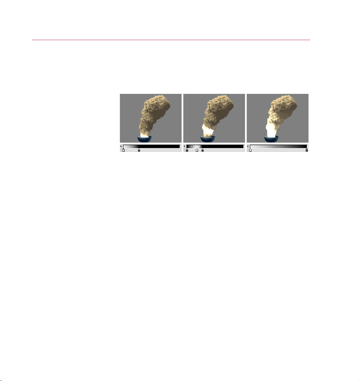
You can eas ily adjust the
lumino sity of the par ticles
over the ir life time. T his
is a power ful effec t that
allows y ou to cre ate roc ket
exhau sts or any type of
glowin g re.
A white color on the gradient means the puffs will stay the same size or luminosity.
A black color means zero radius or no luminosity, while gray values are intermediate
values. High variation in the gradient will create random volume sizes.
Luminosity
For details on using gradients, look up ‘Using gradients’ in the index.
The Luminosity gradient controls the amount of additive pixel blending over the
particle’s lifetime. A white color gives the luminosity value you dened on the Globals
page; a black color returns no luminosity effect at all; and grays give intermediate
values.
The left and right edges of the gradient correspond to the time of the particle’s birth
and death respectively.
Color Mix, Color
For details on using gradients, look up ‘Using gradients’ in the index.
This gradient controls the color mixing, over the particle’s lifetime, between the puff
color set on the Globals page and the color calculated by the Age Color gradient.
So it is the combination of the Globals Color, Age Color and Age Color Mix gradients
that gives the result. Each gray value represents a mixing amount between the base
color (set on the Globals page) and the color generated by the Age Color gradient.
A pure black means that 100% of the base color set on the Globals page is used to
draw the puffs; none of the Age Color is mixed into the particle color. A pure white
will color the puff with 100% of the Age Color gradient; the base color set on the
Globals page isn’t mixed into the Age Color at all. All intermediate gray values will
create a mixing of both color values.
For the Color gradient, the left edge of the gradient controls the color at the puff’s
birth, while the right edge controls the color of the puff when it dies.
Page 39

PYRO CLUST ER
REFERENCE 31
With these set tings, you can
have puf fs change the ir color,
radius a nd luminosit y according
to how far away they ar e from
Distance ef fect s can be
calcu lated either from the
emitter plane (lef t) or from the
position of the e mitter itse lf
the emi tter.
(right).
Distance page
To preview the puffs, on the Shape page enable the Preview option.
Here you can change the color, radius and luminosity of puffs depending on how far
away they are from the emitter. This is useful for effects where the color, shape and
luminosit y changes over distance such as seen in the ames of rocket boosters.
Use Distance Effects, Use Emitter Plane
The par t of the sphere i nside
which distan ce eff ects t ake
place is dene d by the Near
Range a nd Far Ran ge values.
If the Use Emitter Plane option is enabled, the distance of puffs will be measured
from the emitter’s plane rather than from the emitter’s origin.
Near Range, Far Range
Near Ra nge
Emitt er
Far Rang e
These two parameters dene the radii of two concentric spheres placed around
the emitter; together they dene a ‘cavity’ within which distance ef fects can be
applied. Puffs in this cavity between the inner and outer spheres may have their color,
radius and luminosity adjusted according to how far away they are from the inner
sphere. If you want the gradients to control puffs the moment they are emitted, set
Near Range to 0.
Page 40
32 REFERENCE
PYRO CLUST ER
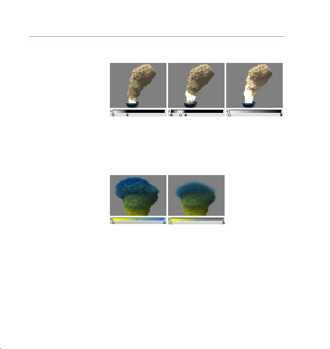
The Lum inosit y gradient con trols
the luminosit y of puf fs within
With the Color gradien t you
have two g radie nts in one. A
gradie nt controls the color
(lef t) whil e another contr ols the
transp arency (rig ht) of puffs in
the cavity.
the cavity.
Radius, Luminosity
For details on using gradients, look up ‘Using gradients’ in the index.
These gradients control the radius and luminosity of puffs depending on their distance
from the cavity’s inner wall (see ‘Near Range, Far Range’ above). The left edge of the
gradient represents the Near Range value, the right the Far Range value. A white color
on the gradient means the puffs will remain the same size or luminosity. Black means
zero radius or no luminosity, while gray values are intermediate values.
Color Mix, Color
For details on using gradients, look up ‘Using gradients’ in the index.
With the Color Mix and Color gradients you can control how the color of puffs in
the cavity should change. As with the Radius and Luminosity gradients, the left
edge of the gradient represents the Near Range value, the right edge represents the
Far Range value.
The color dened by the Color gradient is mixed with the base color of puffs, as dened
on the Globals page. The Color Mix gradient controls how these two colors are mixed.
White means only the color of the puffs inside the cavity is used, while black means
only the base color is used; with gray values, these two colors are mixed.
In addition, the Color gradient includes an alpha gradient that enables you to control
the opacity of puffs in the cavity.
Page 41
PYRO CLUST ER
REFERENCE 33
These s etti ngs are a lmost
identical to th ose on th e
Distance pag e. To switc h on the
cylindrica l effe ct, e nable the
Use Cyl.Dist ance Ef fect s optio n.
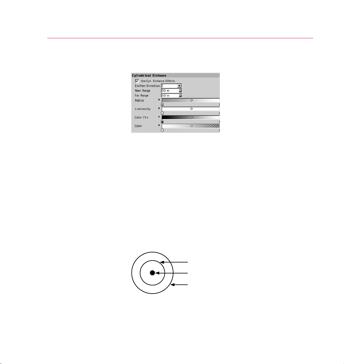
Cylindrical Distance page
If you want to preview puffs while making changes to parameters, enable
the Preview option on the Shape page.
With these settings, two invisible concentric cylinders are notionally positioned on
top of the emitter, facing in the direction that particles are being emitted. Puffs in
the cavity between the inner and outer cylinders may have their color, radius and
luminosity adjusted according to how far away they are from the inner cylinder.
This enables you to create effects that are more or less cylindrical in shape, such as
smoke forming around a column of re. This is contrast to the sphere used on the
Distance page.
Use Cyl. Distance Effects
If you want puffs that are in the cavity to change in color, radius or luminosity
depending on how far away they are from the inner cylinder wall, enable this option
and set the parameters on this page as desired.
The cy lindri cal cav ity inside
which distan ce eff ects t ake
place is dene d by the Near
Range a nd Far Ran ge values.
Emitter Direction
Set this option to the direction in which the emitter emits particles.
Near Range, Far Range
Near Ra nge
Emitt er
Far Rang e
These two values dene the size of the cylindrical cavity in which puffs will be
inuenced. Puffs in this cavity may have their color, radius and luminosity adjusted
using the gradients on this page. If you want the gradients to control puffs the
moment they are emitted, set Near Range to 0.
Page 42

34 REFER ENCE
PYRO CLUST ER
Radius, Luminosity
For details on using gradients, look up ‘Using gradients’ in the index.
These gradients control the radius and luminosity of puffs depending on their distance
from the inner cylinder wall. The left edge of the gradient represents the Near Range
value, the right edge represents the Far Range value. A white color on the gradient
means the puffs will stay the same size or luminosit y. A black color means zero radius
or no luminosity, while gray values are intermediate values.
Color Mix, Color
For details on using gradients, look up ‘Using gradients’ in the index.
With the Color Mix and Color gradients you can control how the color of puffs in
the cavity should change. As with the Radius and Luminosity gradients, the left
edge of the gradient represents the Near Range value, the right edge represents the
Far Range value.
The color dened by the Color gradient is mixed with the base color of puffs, as dened
on the Globals page. The Color Mix gradient controls how these two colors are mixed.
White means only the color of the puffs inside the cavity is used, while black means
only the base color is used; with gray values, these two colors are mixed.
In addition, the Color gradient includes an alpha gradient that enables you to control
the opacity of puffs in the cavity.
Page 43
PYRO CLUST ER
REFERENCE 35
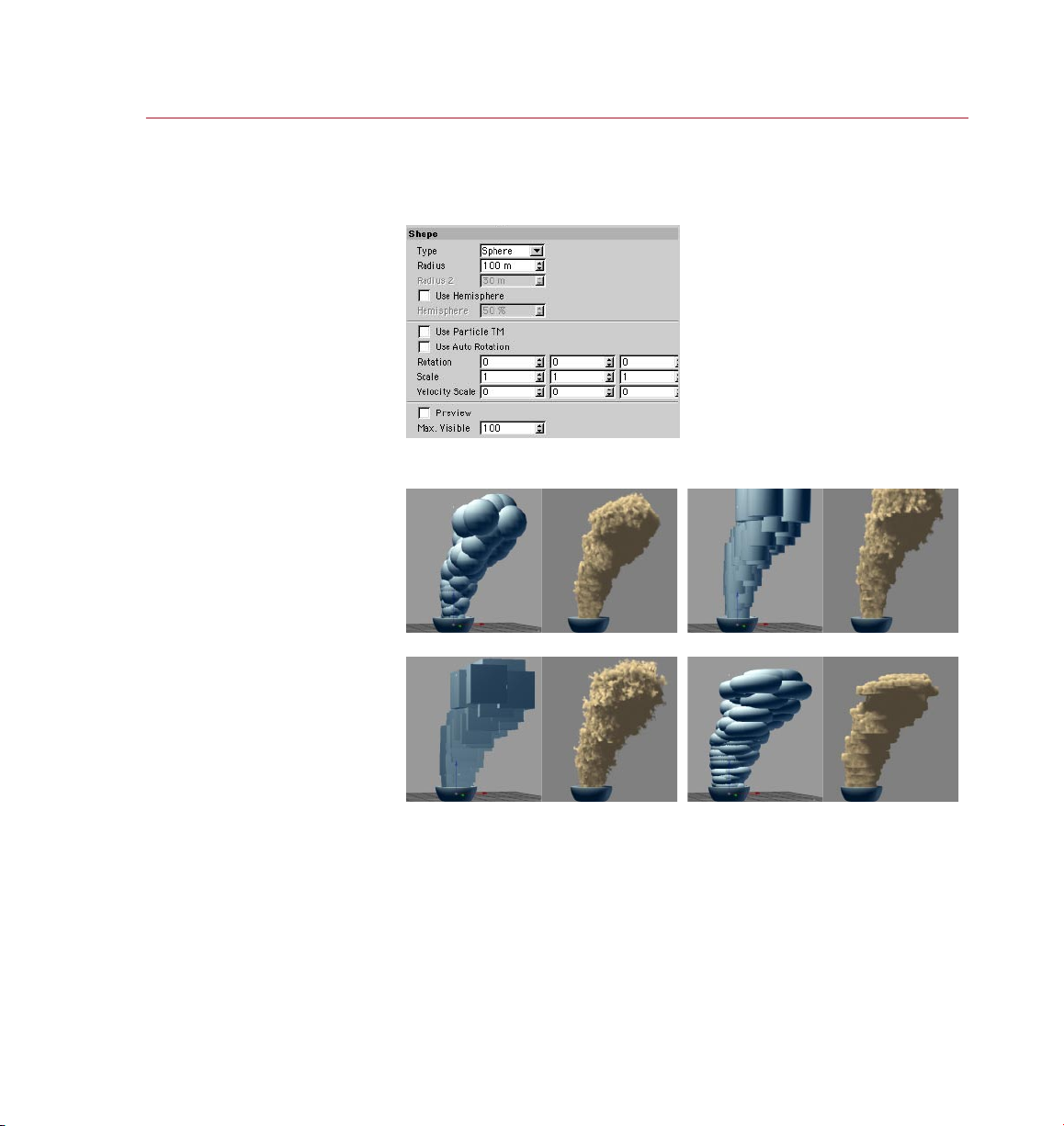
Pyro Clust er puf fs don’t have
to be spherica l. They c an
also be c ylindrical , cuboid or
shape d like don uts.
Puff s may have on e of four
shape s: Sph ere, Cy linde r, Box
or Torus Th e shape you choose
will have a signi cant effec t
on the re ndered result, as
demon strate d here.
Shape page
If you want to preview puffs while making changes to parameters, enable
the Preview option on the Shape page.
Type
Spher ical volume in viewport and render ed. Cylindrical v olume in viewport and rende red.
Box volu me in vie wpor t and ren dere d. Torus volume in vie wpor t and rendere d.
Choose the shape of the puffs from Sphere, Cylinder, Box or Torus. Note that the
preview in the viewport shows the maximum volume that the rendered effect will
occupy. Often, the rendered effect will be smaller than the preview owing to the
nature of the fractal noise that is applied during rendering.
Page 44
36 REFER ENCE
PYRO CLUST ER
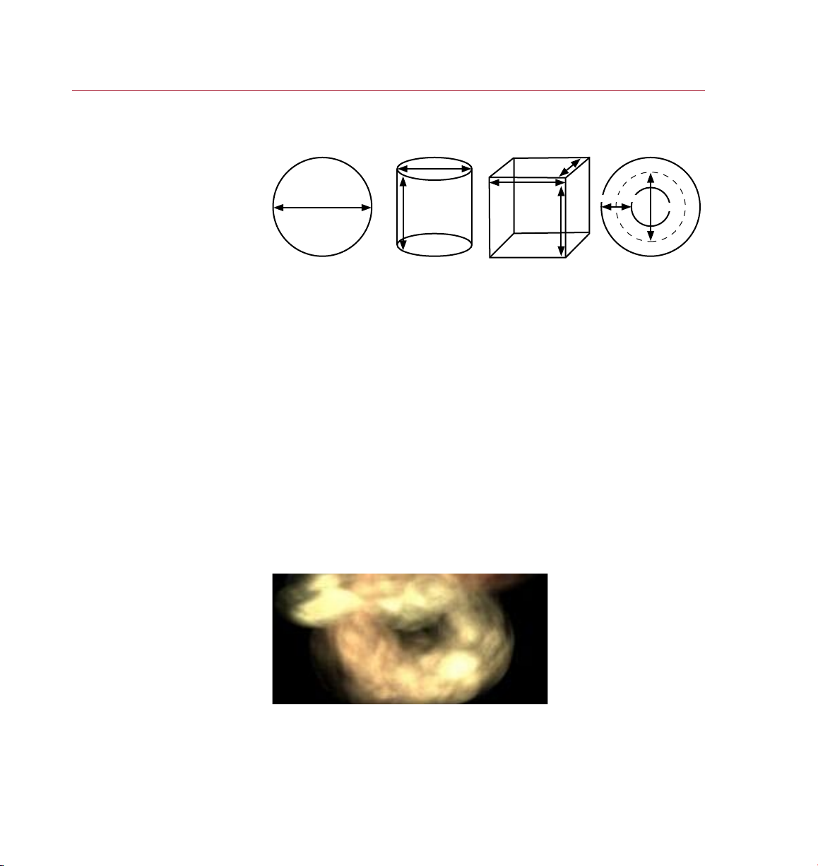
Radius and Radius 2 dene the
size of th e puff s. Their exac t
meani ng depe nds on th e shape
of the puffs.
Radius, Radius 2
The Radius 2 parameter is only available when Type is set to Torus.
Radius
Radius
Spher e Cy linde r Box Torus
Radius
Radius
Radius
Radius
Radius 2
Radius
These parameters set the maximum size of the puffs. The meaning of the values
depends on the shape chosen using the Type drop-down list. The puffs will usually be
smaller than this size when rendered because fractal noise is applied during rendering
that removes parts of the puffs to literally car ve out a realistic, complex shape.
Use Hemisphere, Hemisphere
The Hemisphere parameters are only available when Type is set to Sphere.
If you have chosen a spherical shape for the puffs and you don’t want to use a
whole sphere, enable the Use Hemisphere option and t ype the percentage of the
sphere that you want removed into the Hemisphere box.
Use Particle TM
For this function to work, the particles must be rotating, i.e. have a non-zero
Rotation value on the emitter’s Particle page.
If you enable this option, PyroCluster will use the particle’s transformation matrix to
calculate the rotation of any puff or atmospheric effect.
Here, all informatio n is base d on
the vel ocity vecto r only. A par ticl e
spinning in one p lace (no moveme nt)
will still res ult in a st atic, s pheri cal
puff. To match the PyroCl uster p uffs
to the particle movement or rotation
or both, ensur e that the p arti cles
truly m ove thro ugh space. Rotation
witho ut movem ent make s no sense
for clo ud syst ems.
Use Auto Rotation
If you enable this option PyroCluster will analyze every particle and the velocity vector
of every particle. The puffs will acquire the rotational change of every single particle
in the attached particle system.
Page 45
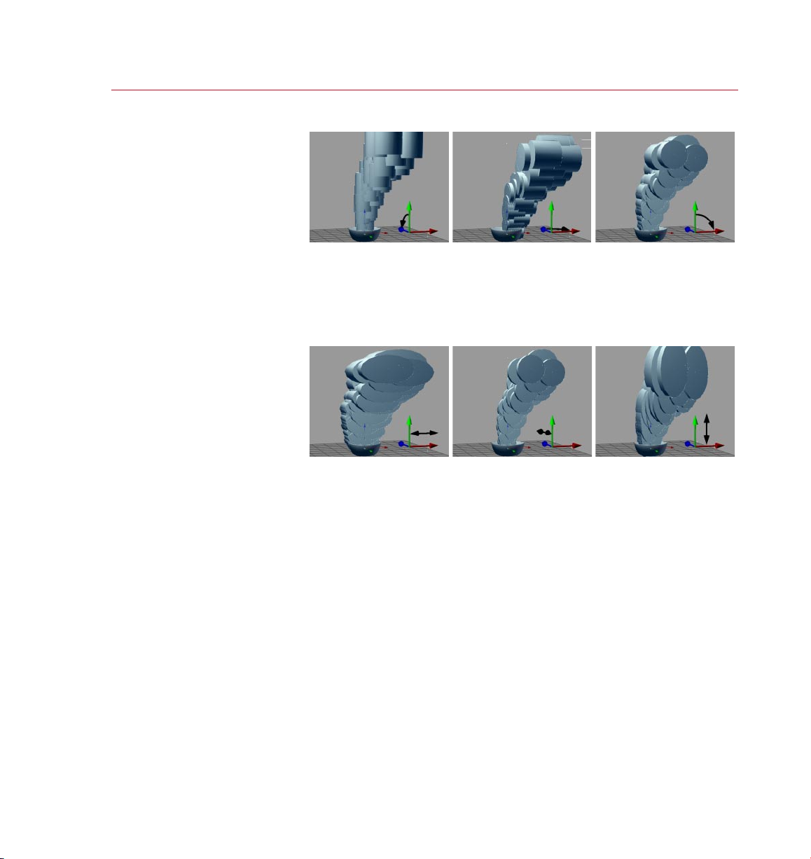
PYRO CLUST ER
REFERENCE 37
You can rot ate puf fs
about any axis.
Puff s can be sc aled
along any axis.
Rotation
Rotate X = -90. Rotate Y = 90. R otate Z = 9 0.
These input boxes enable you to rotate puffs about any axis. If you are using spherical
shapes for puffs, rotation will make no difference to them.
Scale
Animate each of the scale values to create dramatic moving clouds.
Scaling along the X-axis. Scaling along the Y-axi s. Sca ling al ong the Z-axis.
These input boxes enable you to scale puffs along any axis. A value of 1 represents
the normal size without any scaling applied to it.
Velocity Scale
See also ‘Use Auto Rotation’ above.
This option will stretch puffs in relation to their velocities. For example, a starship going
into warp drive might visibly stretch just before it disappears into hyperspace.
Preview, Max. Visible
Enable this option if you are previewing the puffs in the viewport while you are
making changes to parameters. The Max. Visible value controls the maximum number
of puffs previewed on-screen at any one time.
Page 46
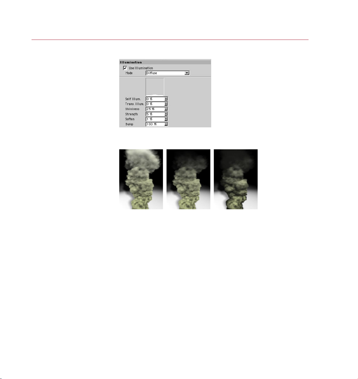
38 REFER ENCE
PYRO CLUST ER
Pyro Clust er effects can be
lit in sev eral ways using the
The ty pe of illumination used
can dram atica lly change the look
of a Pyr oClus ter ef fect .
Illumination page
options on this p age.
The illumination of atmospheric effects is one of the keys to successful and believable
animation. Without light, there’s nothing to see.
Use Illumination off. Diffuse l ightin g. Ray Ang le light ing.
Use Illumination
Enable the Use Illumination option to activate Illumination effects.
Mode
Diffuse
Use Diffuse lighting for clouds and smoke effects.
Use this option if you want to employ a diffuse lighting method. The examples
above show the difference between the different illumination models. Diffuse
lighting spreads the light within the puff itself.
Ray Angle
Use Ray Angle lighting for re and smoke effects.
Enable this option if you want to use the Ray Angle lighting method. The example
on the right, above, shows how Ray Angle illuminates according to the line of sight
to the light source.
Page 47
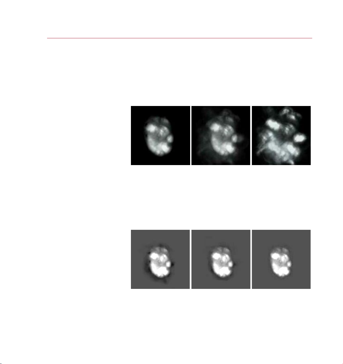
PYRO CLUST ER
REFERENCE 39
Self Il lum. se t to 0% (left),
10% (center) and 100% (right).
Bump
Choose Bump to set the Volume Tracer engine into a special volumetric bump
shading mode (also known as voxel rendering). This method uses true phong
shading algorithms (adopted for volume tracing) to render the 3D volume.
To create a specular highlight only (without any bump structure), set the Bump value
at the bottom of the page to 0% or use Ray Angle only. See also ‘Bump’ below.
Self Illum.
If you increase the Self Illum. value above 0, PyroCluster will add light to each rendered
puff even when the cloud is completely in shadow. A value of 100 means that the puff
color set on the Globals tab is drawn regardless of the inuence of any other light
on the puff. If you set this value to 50, only half of the puff’s color intensity is taken
into account, while the other half of the brightness is generated by the light source.
This feature is useful when you are working with attenuated lights. If you leave this
value at 0, cloud areas with no light will be drawn as pure black.
Trans. Ill um. set t o 0% (le ft),
50% (ce nter) and 100% (r ight) .
Trans. Illum.
Many rendering systems interpret a surface that receives no light as a pure black
surface. This makes sense for 3D geometry and in some cases it is also good for gas
or cloud effects. But if you take a close look at the images above, you’ll see that there
are situations when it looks wrong if that rendering method is used.
Page 48
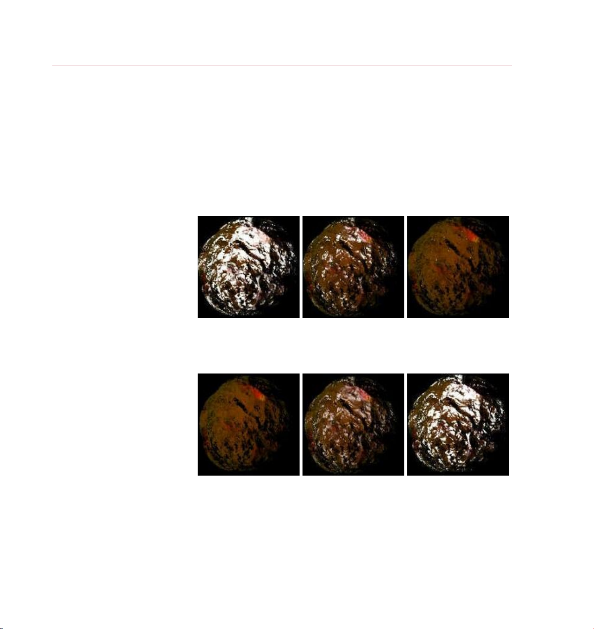
40 REFERENCE
PYRO CLUST ER
Shinin ess set to 0% (le ft),
33% (cen ter) and 100% (ri ght).
In the examples above, a smoke cloud is rendered on a grey background; there is
one spotlight that illuminates the smoke. As you can see in the left-hand image, the
edges of the cloud are, by default, pure black. Trans. Illum. helps you to soften areas
in the volume that do not receive light, such as these edges.
A value of 0 will render all areas, regardless of their illumination level. Set Trans. Illum.
to its maximum value of 100 and it will only render those areas that are totally in the
hot spot of the light cone.
Shininess
If you use very transparent effects, strange highlights may appear due to the
volumetric nature of the volume tracer.
The Shininess value controls the amount of ‘glaze’ on the volume’s surface. Increasing
the Shininess value will reduce the size of the specular highlights.
Streng th set to 0 % (lef t),
33% (cen ter) and 100% (ri ght).
Strength
Strength controls the intensit y of the specular highlight. Higher values will result in
brighter (whiter) specular highlights.
Page 49

PYRO CLUST ER
REFERENCE 41
Soften set to 0 % (lef t),
50% (ce nter) and 100% (r ight) .
Bump se t to 0% (left) ,
33% (cen ter) and 100% (ri ght).
Soften
This effect will be visible only when using more than one light.
When Strength is high and Shininess is low you might see harsh backlight ef fects.
Increasing the Soften value will smooth out the regions affected.
Bump
The Bump value has the most impact on the overall look of the nal effect. Higher
values will result in more surface deformation. This value can also be set negative
to invert the effect.
Page 50
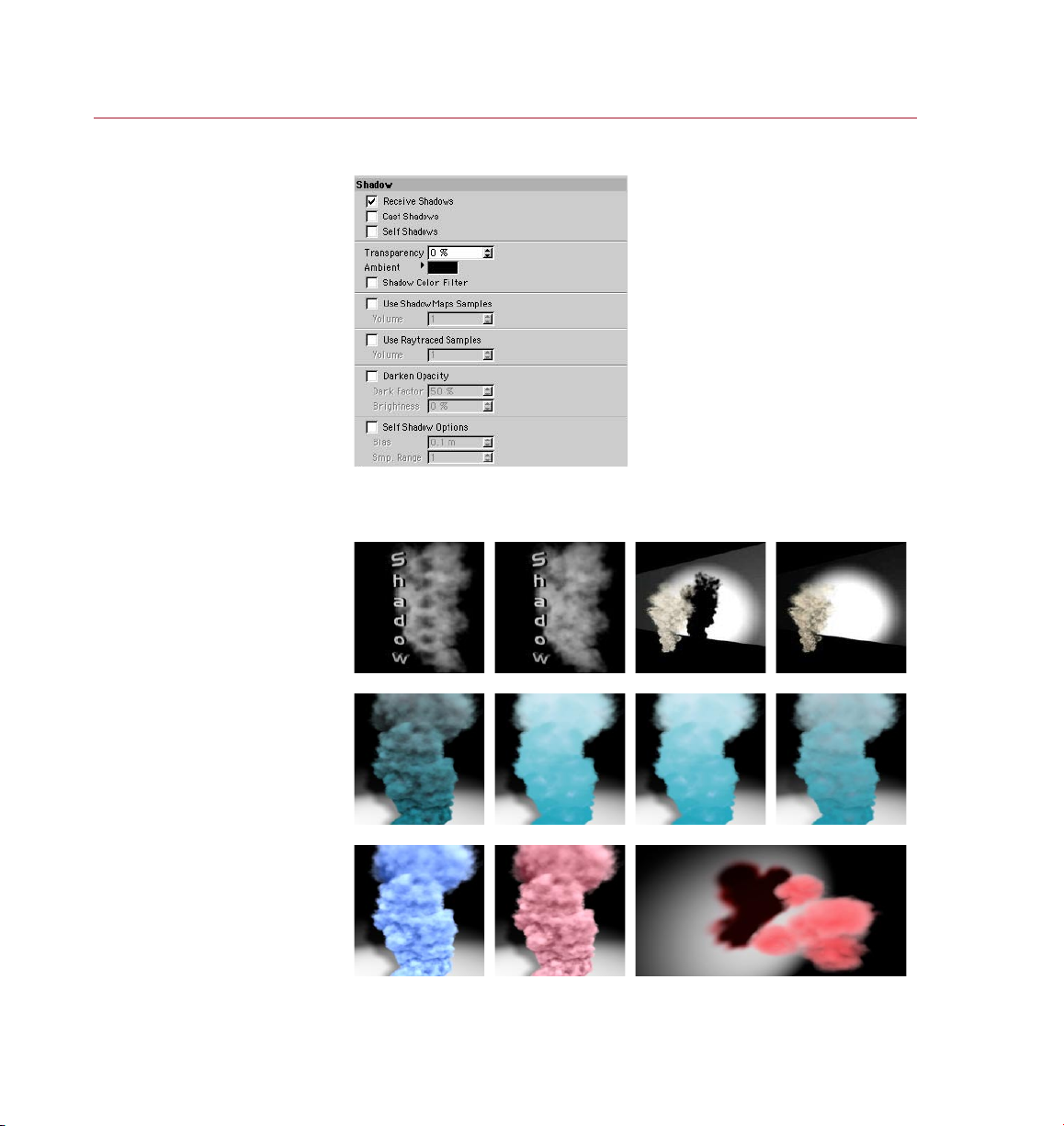
42 REFER ENCE
PYRO CLUST ER
they can also have self shadows
Pyro Clust er effects have a
unique range of o ptions to
provide contr ol over shadows .
Pyro Clust er puf fs can no t only
receive and ca st shad ows, but
of any col or and tra nspar ency,
and even cast colored s hadows.
Shadow page
PyroCluster creates 3D volumetric effects using both shadow casting and transparency
information. PyroCluster effects can receive shadows, can cast shadows of any color,
can have self shadows and shadows that have their own ambience.
Recei ve Shadows on. Recei ve Shadows off. Cast Sh adows on . Cast sh adows off.
Self Sh adows on . Self Sh adows of f. Transpar ency = 0 %. Transpar ency = 70 %.
Ambie nt colo r blue. A mbient color red. Shadow C olor Filter enabled.
Page 51
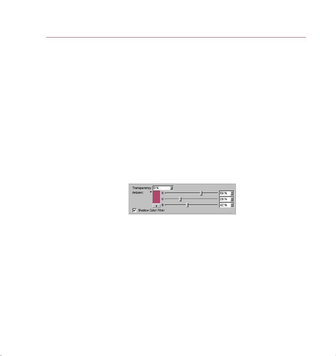
PYRO CLUST ER
REFERENCE 43
Click the small t riangle to open
and clo se the ambient options .
Receive Shadows
Enable this option if you want other objects in the scene to be able to cast shadows
onto PyroCluster puffs.
Cast Shadows
Enable this option if you want puffs to cast shadows onto other objects.
Self Shadows
Enable this option if you want the PyroCluster effect to cast shadows onto itself.
Raytraced Samples (see below) create the most realistic effects, but keep in mind
that they also take the longest time to render.
Transparency
Normally the base color for shadows is black. Sometimes, depending on global
illumination or other diffuse lighting effects, these shadows may look too dark for
your scene. The Transparency value allows you to adjust the intensity of shadows,
where 0% is opaque and 100% is completely transparent (i.e. invisible shadows).
Ambient
Self Shadows must be enabled for this option to have an effect.
The appearance of a shadow is decided by three things: rstly, the color and intensity
of the light sources; secondly, the opacity, color and texture of the object the light
is shining onto; thirdly, the opacity, color and texture of the object that receives the
shadow. This Ambient option enables you to add a fourth element to the equation:
a color for the shadow itself.
Because this is a property of the puff itself, it affects only shadows cast onto the puff
(i.e. self shadows). When rendered, this ambient color can look like a glow.
Page 52
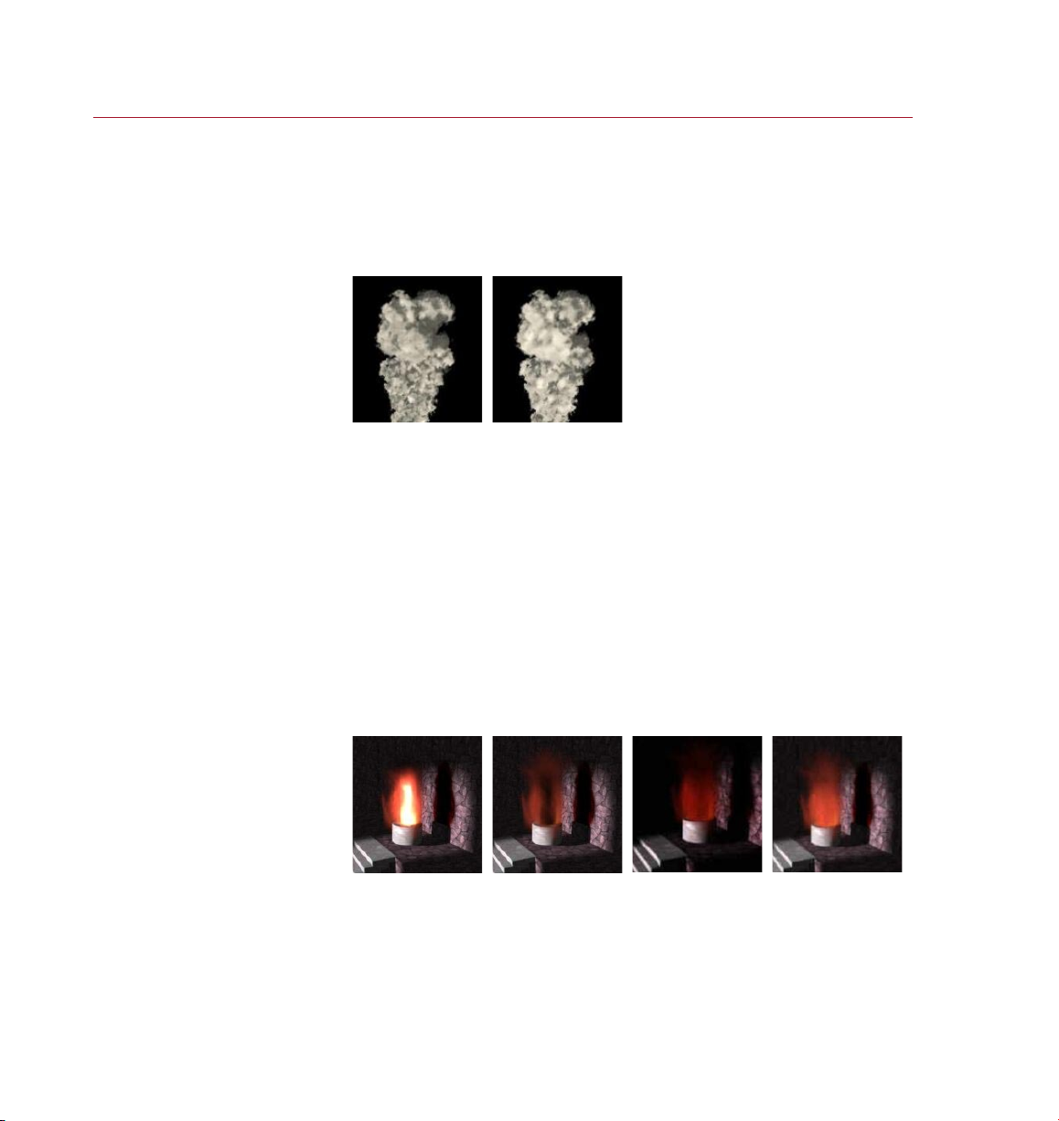
44 REFERENCE
PYRO CLUST ER
Shadow Color Filter
Enable this option if you want to use colored shadows. The color of the shadow is
taken from the color and intensity of the volume effect of the puff — for example, a
green puff will cast a green shadow.
Use ShadowMaps Samples, Volume
Volume se t to 0.8 (l eft)
Darken O pacit y off ers ano ther
way to brighten or d arken puffs.
and 1 (ri ght).
Enable the Use ShadowMaps Samples option if you want to limit the amount of volume
sub-sampling for shadow maps in order to speed up rendering. A Volume value of 1
means that the entire volume is analyzed to generate self shadows and cast shadows.
Use lower values to reduce sub-sampling for shadows that need less detail.
Use Raytraced Samples, Volume
Raytraced shadows don’t use shadow maps and hence are more accurate and produce
better results. However, the downside is that they take much longer to render.
Use the Volume value to limit the amount of volume sub-sampling used for raytraced
shadows, and also to speed up rendering. A Volume value of 1 means that the entire
volume is analyzed to generate self shadows and cast shadows. Use lower values to
reduce sub-sampling for shadows that need less detail.
Darken Opacity
Dark Fac tor -4 0%
Brightness 0 %.
Dark Fac tor 30%
Brightness 0 %.
Dark Fac tor 30%
Brightness 50%.
Dark Fac tor 30%
Brightness 100 %.
If this option is enabled, PyroCluster will use a different method to shade the puff.
Light will be added or subtracted based on the puff’s current opacity. Denser areas
can be made darker or brighter with the Dark Factor and Brightness values.
Page 53
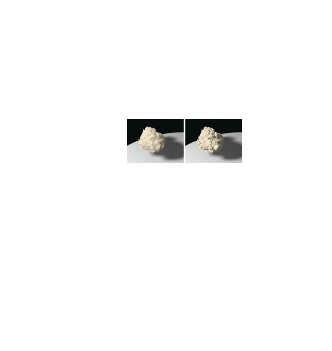
PYRO CLUST ER
REFERENCE 45
Self Sh adow Opt ions
disab led (le ft) an d enabl ed
(right) with Bias set to 1.0
and Smp. R ange se t to 1.0.
Dark Factor
This value controls the amount of light that is added or subtracted based on the
transparency of different areas of the puffs. Higher, positive values will darken areas of
low transparency; negative values will brighten areas of low transparency.
Brightness
This value controls how dark the areas should become when you use a Dark Factor.
A Brightness value of 0% will add no extra light to the dark areas created by the
Darken Opacity option, while higher values will add light to these darker areas.
Self Shadow Options
A soft shadow map always creates a soft self shadow. Sometimes you may not want
this, hence PyroCluster provides control over a volume effect’s shadow map. Enable
Self Shadow Options to make available the Bias and Smp. Range controls. These
controls af fect self shadows only, i.e. they don’t affect cast shadows.
Bias
Controls the distance between the shadow and the object.
Smp. Range
Denes the softness of the shadow, from 0 (hardest and quickest to render) to 20
(softest and longest to render).
Page 54
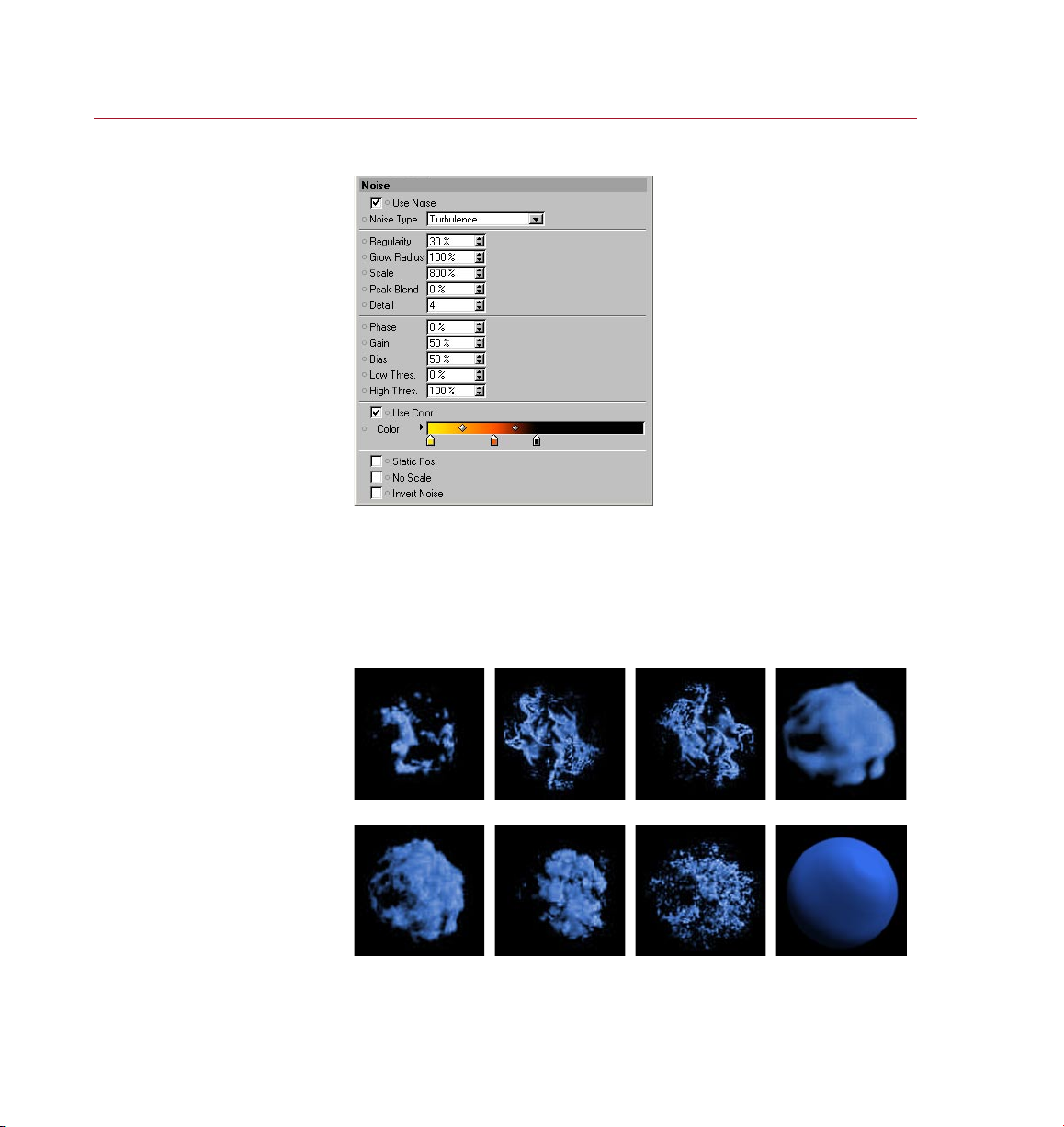
46 REFERENCE
PYRO CLUST ER
On this page you can crea te
true volumetric nois e
effe cts — effec ts that w ill
chang e as a came ra moves
throu gh a volum e.
Noise page
Here you can create real 3D volumetric noise effects where the effect will change as
you move into the volume.
Use Noise
This switches the noise engine on and off.
Eight no ise ef fect s provi de
plent y of ver satility.
Noise Type
Gaseo us. Fire. Electric. Regula r.
Fract al. Turbulence. fBm Frac tal. fBm Turbulence.
Page 55
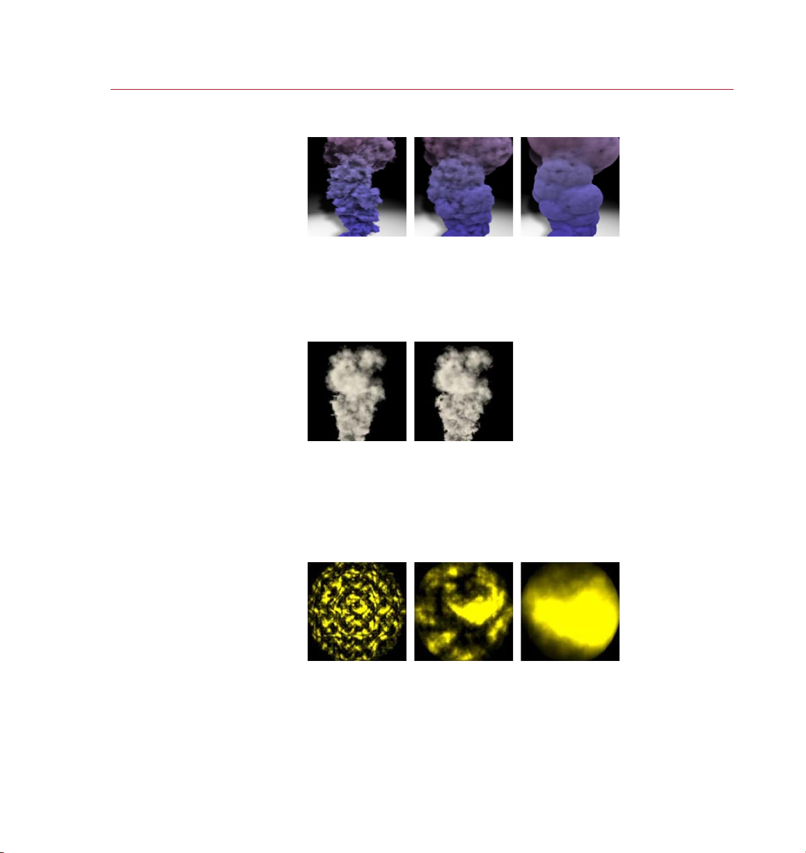
PYRO CLUST ER
REFERENCE 47
Regul arity set to 0% (left),
50% (ce nter) and 100% (r ight) .
Regularity
Regularity controls the feathering of the rendered puffs. By default PyroCluster uses
primitive volumes to render the smoke or cloud effect. To remove visible edges, use
the Regularity value. A value of 100% will create sharp volume edges while a value
of 0% will create feathered volumes.
Grow Radius
Grow Radius set to 0% (le ft)
200% (center) and 1000 % (right).
and 100% ( right).
Scale s et to 50% (lef t),
Most of the time you’ll probably want the noise to grow with the volume — tiny little
wisps just wouldn’t do for a huge volcano cloud. Grow Radius controls the amount
of scaling used for the effect. A value of 100% means that the noise structure grows
at about the same rate as the volume itself. For best results, and for a more turbulent
life, use values between 65% and 80% .
Scale
The Scale value controls the size of the noise pattern. Smaller values result in ner
patterns. Experiment with each scene to nd the best value for Scale, which could be
anything ranging from 0% to 10,000,000%! It just depends on the scene.
Page 56
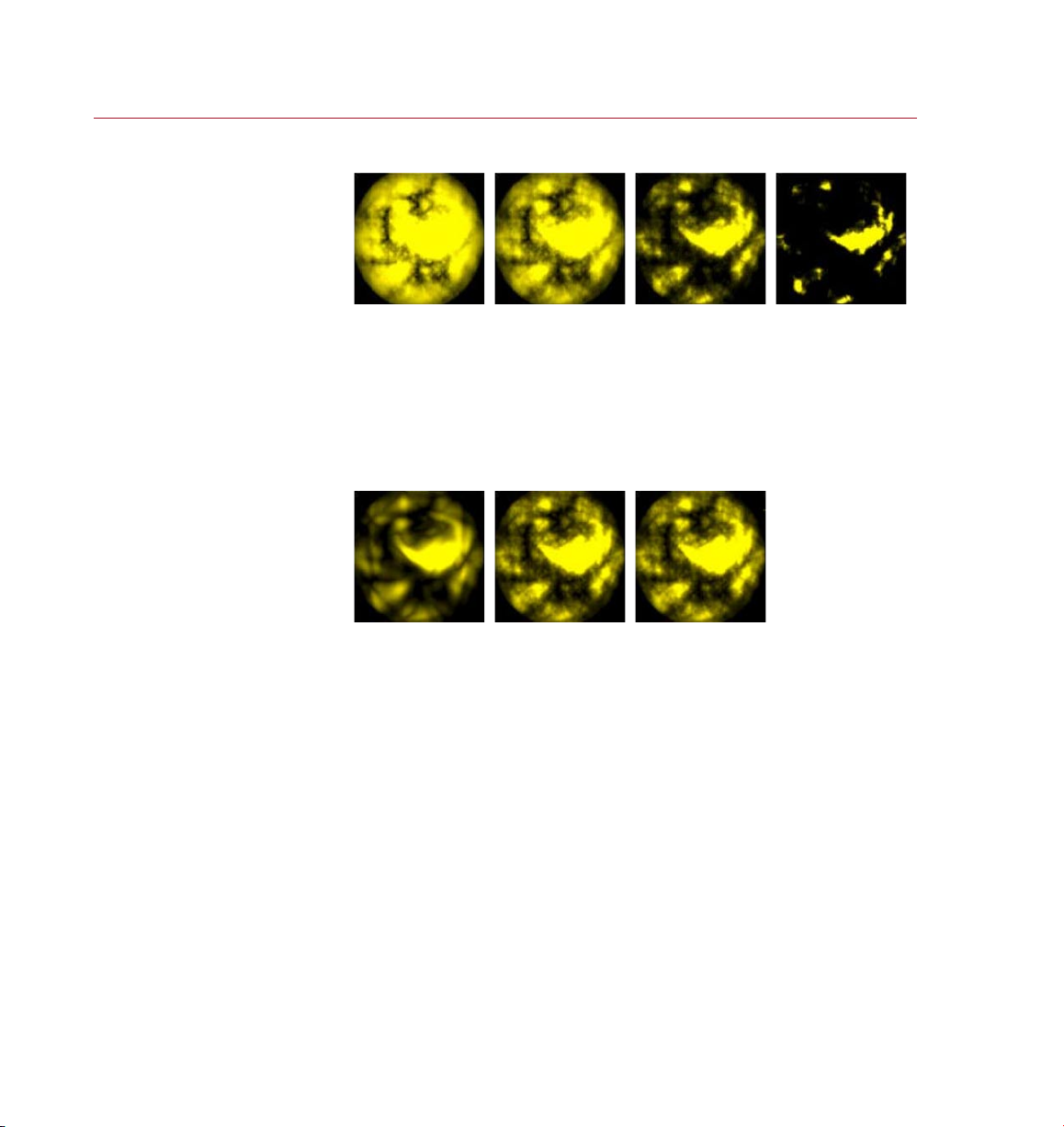
48 REFE RENCE
PYRO CLUST ER
From left to right: Pe ak Blend set
to -60 %, 0 %, 20 0% and 100 0% .
Detail set to 1.0 (l eft) ,
4.0 (center) and 10 (right) .
Peak Blend
The Peak Blend value controls the size of the hot spots in the effect. Increasing values
will shrink the effect and produce denser hot spots. Negative values will widen the
effect, creating an inverted effect where the hot core grows to the outside. With fBm
Fractal noise, Peak Blend controls the smoothness of the fractal noise edges.
Detail
In general, avoid using values above 10 because this will tend to slow down
rendering without adding much detail.
Detail controls the number of samples per effect. Increasing this value will create more
subdivisions, resulting in more detail. Lower values will render considerably faster.
Phase
Phase controls the angular change of the effect. Animate this value to get internal
cloud movement — the faster this value changes, the faster the movements of the
effect. For a gas-like effect, go for a slow phase change per frame; for re, make the
change more dramatic.
Page 57
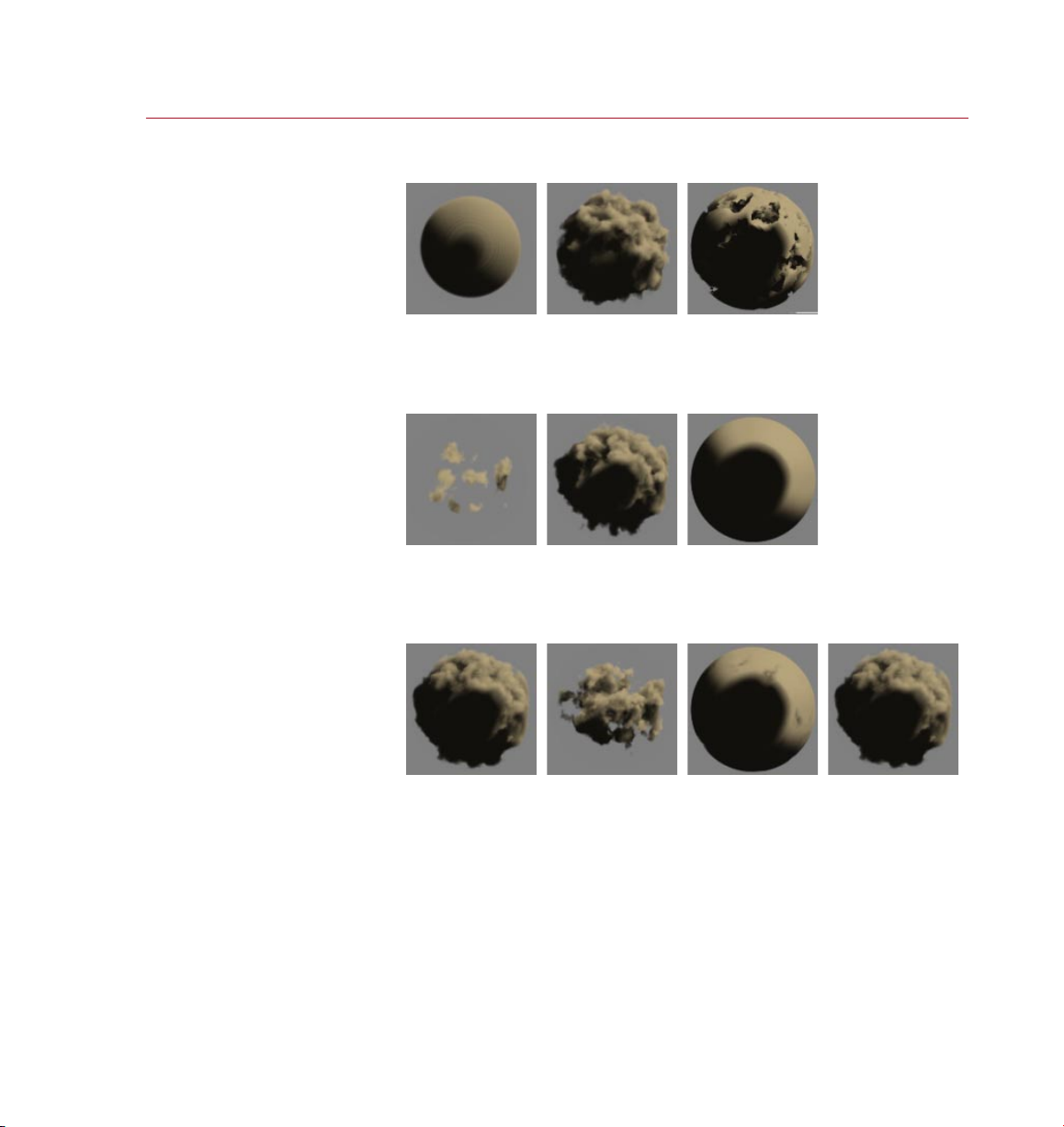
PYRO CLUST ER
REFERENCE 49
Gain
50% (ce nter) and 100% (r ight) .
50% (ce nter) and 100% (r ight) .
From left to right: Low Thres . set
to 0% and 5 0%, High Thres. se t
Gain se t to 0% (left),
Bias se t to 10% (le ft),
to 50% an d 100% .
Gain controls the noise intensity on the inside of the effect. A setting of 50% is used
as the center of intensity (the same number of bright and dark pixels).
Bias
Bias controls the noise intensity on the outside of the effect. A setting of 50% is used
as the center of intensity (the same number of bright and dark pixels).
Low Thres., High Thres.
These values set the low and high clipping limits of the noise range. The clipped
noise range between Low Thres. and High Thres. is stretched to ll the entire range
(0% –100%). Mainly you would increase Low Thres. to create more holes in the noise
and decrease High Thres. to create fewer holes.
Page 58
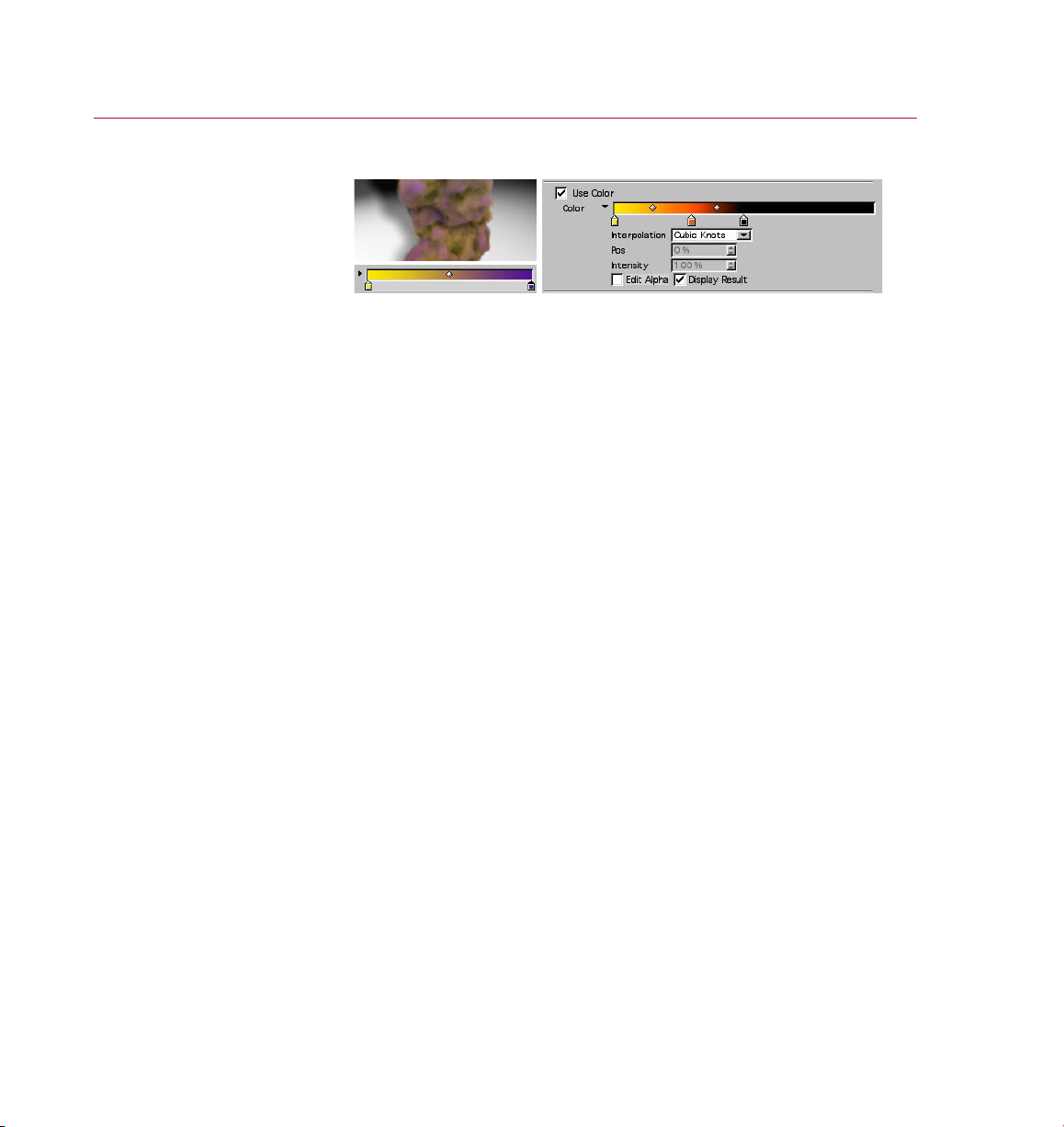
50 REFER ENCE
PYRO CLUST ER
With Use Color enable d, the
color s used in t he frac tal
effe cts ca n be controlle d
direc tly from the Noise page,
overriding th e same se ttings
on the Globals page.
Use Color
If you enable this option the color for the ef fect is taken from the gradient here on
the Noise page rather than from the one on the Globals page.
This gradient controls the coloring of the puff based on the result of the noise render
engine, enabling you to make effects based on the noise itself. When Use Color is
enabled, the left edge of the color gradient is used for all noise values equal to zero
(i.e. transparent) while the right edge of the color gradient is used for all noise values
equal to one (i.e. opaque).
The Noise gradient differs from the Globals gradient in the use of the Edit Alpha option.
Here, the alpha gradient does NOT control the transparency of the noise; rather, it
controls which color is taken to draw the puff. Plain white in the gradient means that
the Noise color only is used, plain black means use the Globals color only — so if the
alpha gradient is completely black and the Use Color option is enabled, this would
produce the same result as if the Use Color option were disabled.
So Use Color enabled, the Noise Color gradient controls the look of the puff — just
the puff; all other color information (Gradient Mode, for example) is taken from the
Globals Color settings.
Static Pos
This option changes the way in which the effect is calculated. Usually the effect eats
into the local space of the individual volumetric pixel (called a ‘voxel’) with the result
that each voxel creates its own puff. However, in some cases you may want to x the
position of the effect and move the puffs through the noise. If this option is enabled,
the effect for all voxels is controlled by screen coordinates.
Page 59
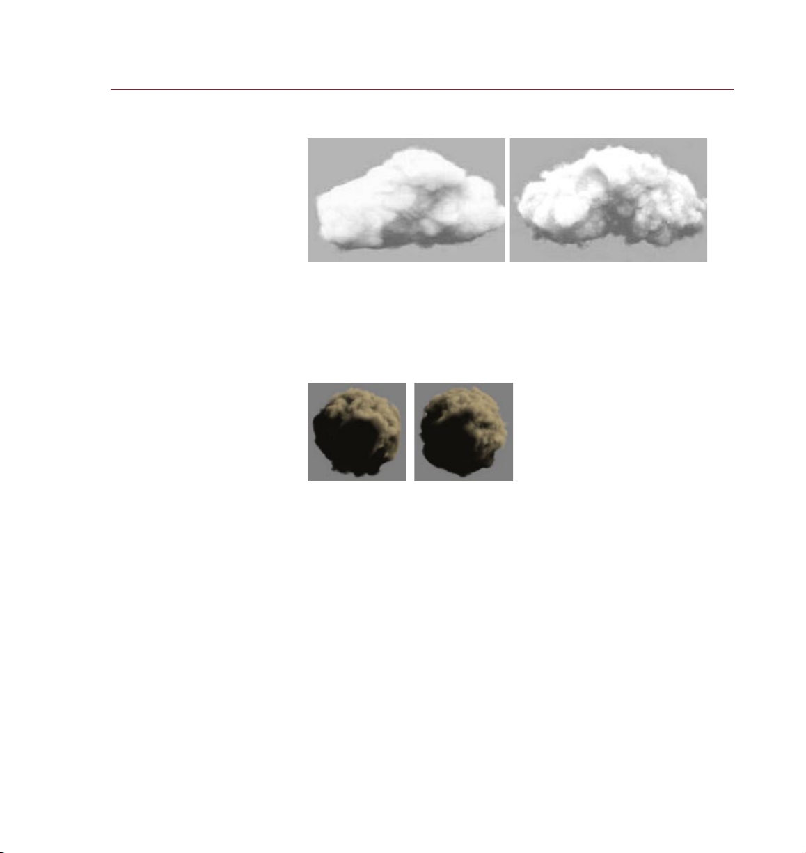
PYRO CLUST ER
REFERENCE 51
No Scal e disab led (le ft)
and ena bled (r ight) .
Norma l noise ( left ) and
inver ted noi se (rig ht).
No Scale
When you scale a puff (using ‘Scale’ on the Shape page) you may want to leave
the scale of the noise function itself unchanged. By default, when scaling a puff,
PyroCluster also stretches the noise volume function according to the Scale values
set on the Shape page. Enable No Scale here to leave the scale of the noise function
unchanged.
Invert Noise
Enable the Invert Noise option to invert all noise values.
Page 60

52 REFERENCE
PYRO CLUST ER
Animating PyroCluster parameters
You can animate any P yroCluster parameter that has a circle next to its name in the
Attribute manager or Material Editor.
To animate a parameter:
- In the Attribute manager or Material Editor, Ctrl-click on the parameter’s circle.
- Repeat the above at a different point in time, using another value, and the
parameter is animated.
For more details on how to animate in the Attribute manager and Material Editor,
please refer to your CINEMA 4D reference manual.
Page 61
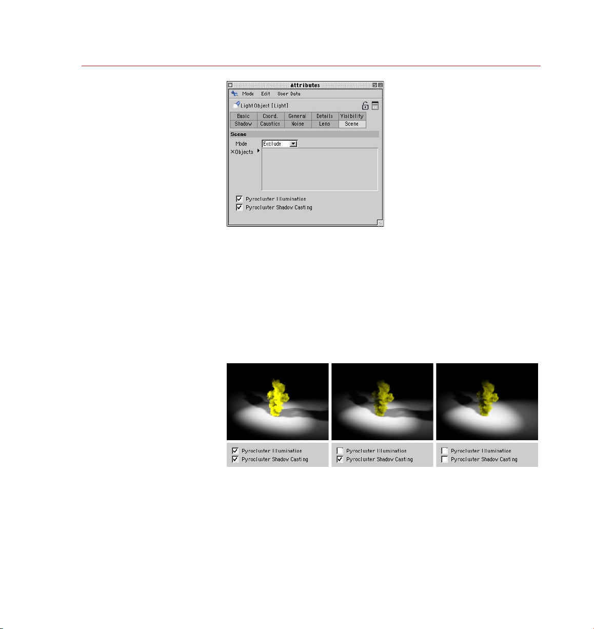
PYRO CLUST ER
REFERENCE 53
Choosing
Light
Sources
For even greater control
over both render times and
the appearance of effects,
each light source in your
scene can be congured to
either inuence or ignore
PyroCluster puffs.
PyroC luste r is a re al volume tracer that use s adv anced volu me calculati ons.
Unfortunately, atmospheric effects usually take a while to render. You must take
care when using several light sources in a PyroCluster scene. On the one hand, one
or two lights are all that you need to light the effect. On the other hand, it is virtually
impossible to light an entire scene using just two lights.
So that you can choose which lights in your scene will inuence any PyroCluster
effects, in the Attribute manager each light source has two options on the Scene
page: P yroCluster Illumination and PyroCluster Shadow Casting.
These are global settings; all PyroCluster ef fects in a scene will be inuenced;
other objects in the scene are not affected by these settings.
You can cho ose how
each li ght source will
affe ct PyroCluster puffs.
To describe the effect of light exclusion, we’ll use the simple scene above. The scene
contains two light sources both pointing towards the Pyrocluster effect, and both set
to cast shadows. Disabling PyroCluster Illumination is useful when you’re trying to
control just the lighting of the PyroCluster effect, leaving shadows as they are. With
both options disabled we see the effects of other light sources.
Page 62

Page 63

2 Tutorials
Page 64

Page 65
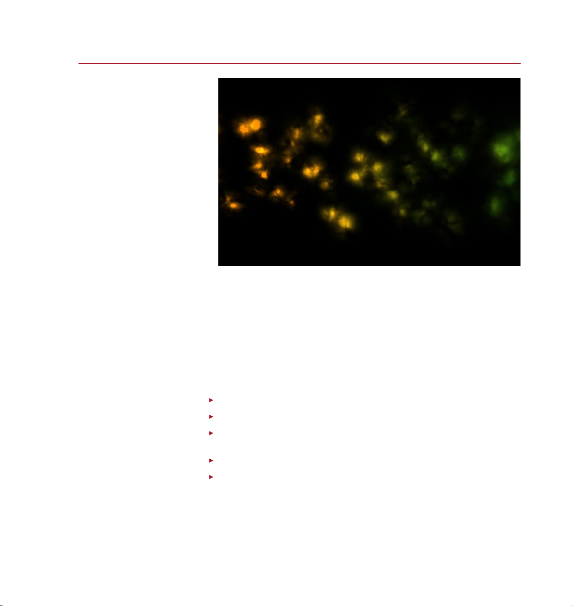
PYRO CLUST ER
Gradient Animation
In this tutorial we’ll learn
how to use PyroCluster’s
gradient sliders to
change the color of
puffs depending on their
distance from the emitter.
TUTOR IAL S 57
PyroCluster features a unique and intuitive way to animate puffs; by ‘puffs’ we mean
particles that have had a PyroCluster material applied to them. While puffs and their
parameters can be animated in the regular way using key frames, PyroCluster also
enables you to animate them using special gradients.
The ‘Gradients’ section (look up ‘using gradients’ in the index) contains all the details
of how these gradients are used to produce a wide range of special effects. Here
we will illustrate how a single parameter (color) can be changed depending upon a
puff’s distance from its emitter. Once you’ve mastered this, creating more complex
special effects is merely a matter of applying these principles to several parameters
at once.
From the main menu, choose Objects > Particle > Emitter.
In the Material manager, choose File > PyroCluster > PyroCluster.
Drag the PyroCluster material from the Material manager and drop it onto the
Emitter in the Object manager.
From the main menu, choose Objects > Scene > Environment.
In the Ma terial ma n ager, choos e File > PyroC l u s ter > PyroCl u s ter -
VolumeTracer.
Page 66
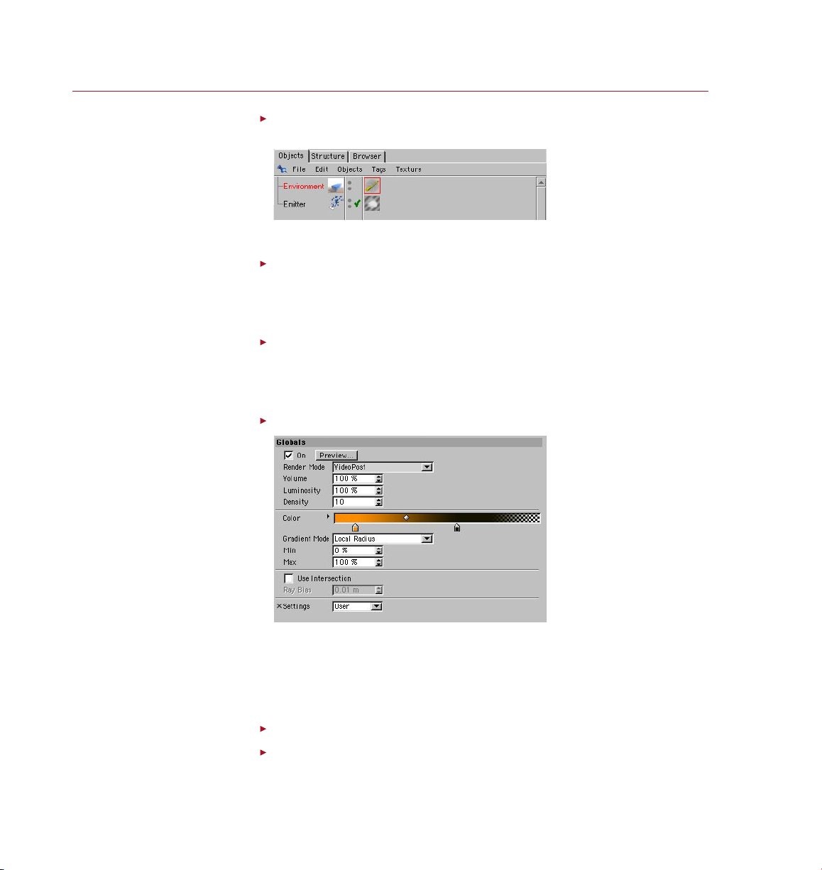
58 TUTO RIAL S
PYRO CLUST ER
As an Env ironm ent obj ect
encom passe s the ent ire sce ne,
apply ing a Volum eTracer to
it mean s that all P yroCluste r
effe cts in t he scen e are
controlled by t his Volum eTracer.
The Glo bals page for a
Pyro Clust er mate rial includes
usefu l preset effects o n the
Settings drop-d own list. Here is
also wh ere you s et the render
mode fo r this PyroCluster
material.
Drag the VolumeTracer material from the Material manager and drop it onto
the Environment object in the Object manager.
We have now completed the basic, minimum set-up for a PyroCluster effect.
In the Material manager, select the PyroCluster material by clicking on it once.
This displays the PyroCluster material settings in the Attribute manager, where we’ll
edit the parameters in a moment. You can alternatively edit the parameters in the
Material Editor instead if you wish. The choice is yours.
In the Attribute manager or Material Editor, on the Globals page, set Settings
to Fire and conrm the dialog that checks if you really want to convert the
parameters.
We will use one of the PyroCluster preset effects for the purposes of this tutorial.
Still on the Globals page, set Render Mode to VideoPost.
The VideoPost mode will render our PyroCluster puffs as a post effect, which will give
us results more quickly. When we create PyroCluster effects we will always need to
decide whether we want the highest quality results produced by the Atmospheric
mode, which takes much longer to render, or whether we can get away with the
much faster VideoPost mode.
On the Distance page, enable Use Distance Effects.
Set Near Range to 100 and Far Range to 500.
Page 67
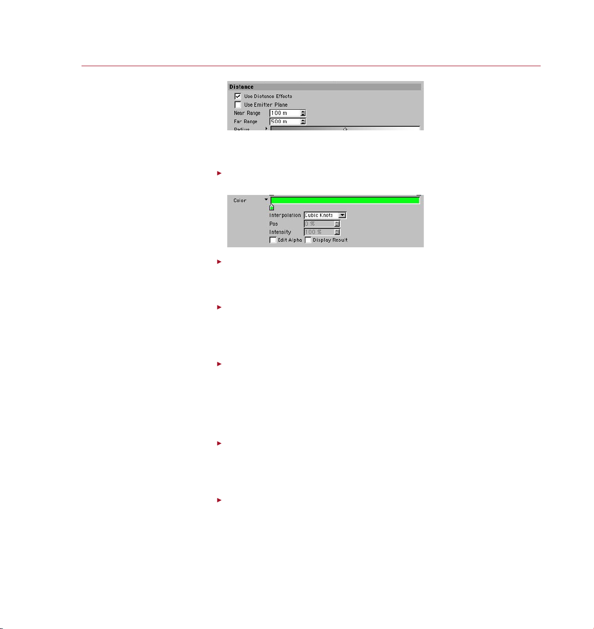
PYRO CLUST ER
TUTOR IAL S 59
The set tings on the Distanc e
page en able us to change the
appea rance of p uffs d epen ding
on how far aw ay they ar e from
On the Di stance page, t he lef t
edge of g radients determines
what happens at the Near Range,
the right edge w hat happ ens at
the emi tter.
the Far Ra nge.
Here we are saying that we want our puffs to begin changing 100 units from the
Emitter and that they should be completely changed when they reach 500 units.
Still on the Distance page, click the small triangle to the left of the Color gradient
to open the Color gradient options.
Disable the Display result option if it is enabled.
We are doing this simply to give us a clearer display in the Color settings, without
the transparency effect of the alpha distracting us.
Double-click on the left-hand color knot below the gradient and use the color
selector to change its color to green.
Here we are saying that the change we want to link to the distance the puffs are from
the emitter is the color of the puffs.
Drag the right-hand knot away from the gradient to delete it.
For simplicity we just want the puffs to turn green, so there is no need for the gradient
to change color here. The left-hand side of the gradient decides what happens at
the Near Range distance, the right-hand side decides what happens at the Far Range.
With this setting, as puffs get further away from the emitter, the more green they will
become, until they hit the Far Range distance when they will be completely green.
In the Object manager, select the Emitter and in the Attribute manager, on the
Particle page, set Birthrate Renderer to 30.
The default birth rate of particles is a bit low; here we are simply increasing the birth
rate so that there will be more particles and we can see the results more clearly.
Render the animation.
Three or four seconds of the animation at a low resolution should be enough for us
to see the results of what we have done. Note that because there is a default alpha
gradient mixed with the Color gradient, the particles not only change color over time
but also fade out gradually.
Page 68

60 TUTO RIALS
PYRO CLUST ER
Summary
There are many, many parameters of a PyroCluster material that can be animated using
gradient sliders on the various parameter pages in the Attribute manager or Material
Editor. Although most of them do very specic and different things, all of them use
gradients to animate changes over time in a similar way to the technique described
here. While we have used VideoPost rendering here for speed, you should be aware
that Atmospheric mode won’t just produce higher quality and slower results, it will
also produce very different results.
Page 69
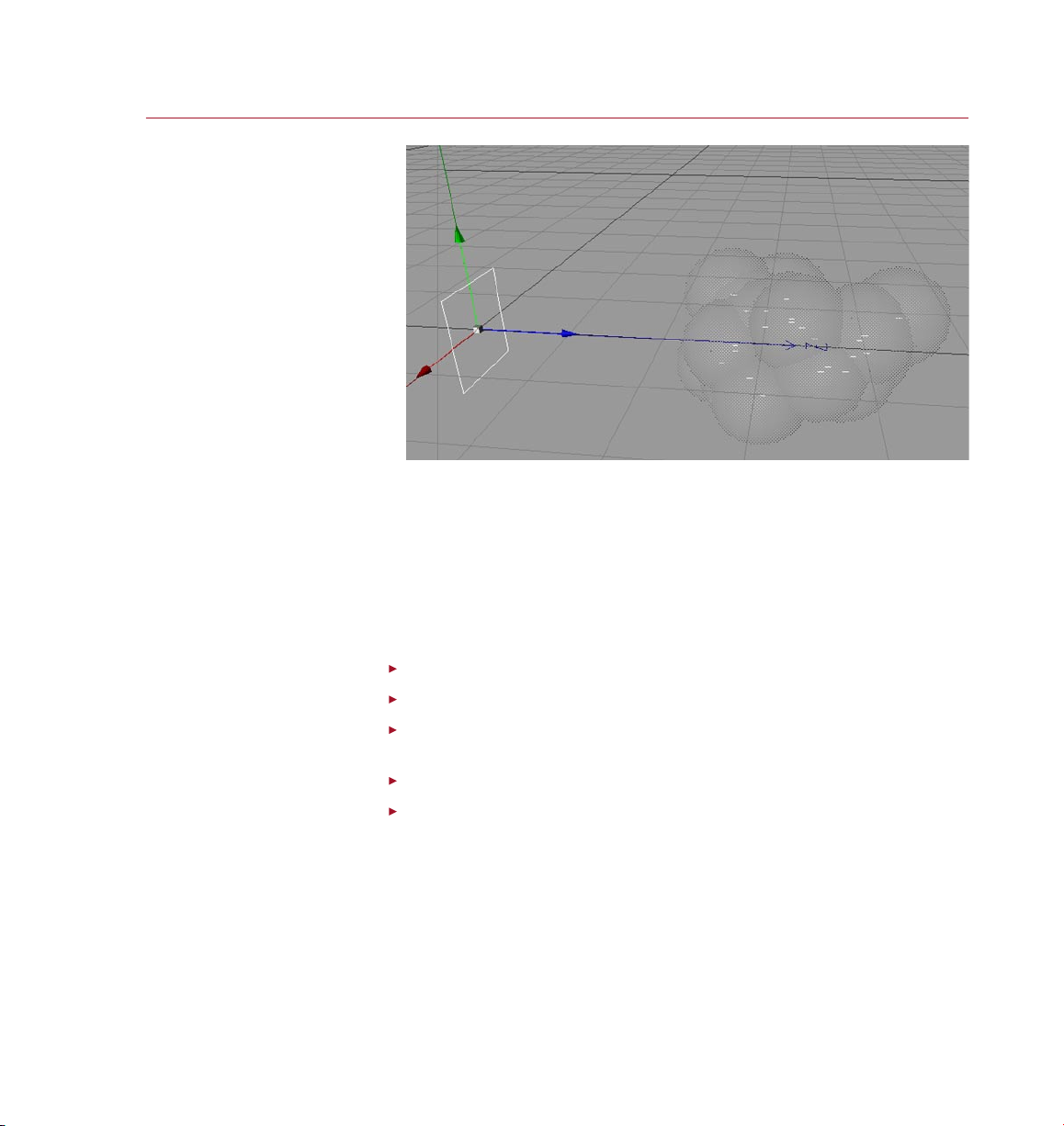
PYRO CLUST ER
TUTOR IAL S 61
Keyframe Animation
The vast majority of a
PyroCluster material’s
parameters can be
animated using keyframes
in exactly the same way as
regular CINEMA 4D objects
and materials.
Keyframe animation is the cornerstone of animation in CINEMA 4D. Just like any
normal CINEMA 4D object or material, we can animate PyroCluster puffs and their
parameters quickly and easily by recording keyframes.
Here we will learn how to animate a single parameter (Radius) using key frames.
Complex animations can be achieved by combining the animation of lots of different
parameters. Almost all the parameters of a PyroCluster material can be animated using
keyframes, which means PyroCluster will never restrict creativity and can of course
interact and be combined with regular CINEMA 4D keyframe animation.
From the main menu, choose Objects > Particle > Emitter.
In the Material manager, choose File > PyroCluster > PyroCluster.
Drag the PyroCluster material from the Material manager and drop it onto the
Emitter in the Object manager.
From the main menu, choose Objects > Scene > Environment.
In the Ma t e rial ma n ager, choo s e File > P yroCl u s ter > PyroCl u s ter -
VolumeTracer.
Page 70
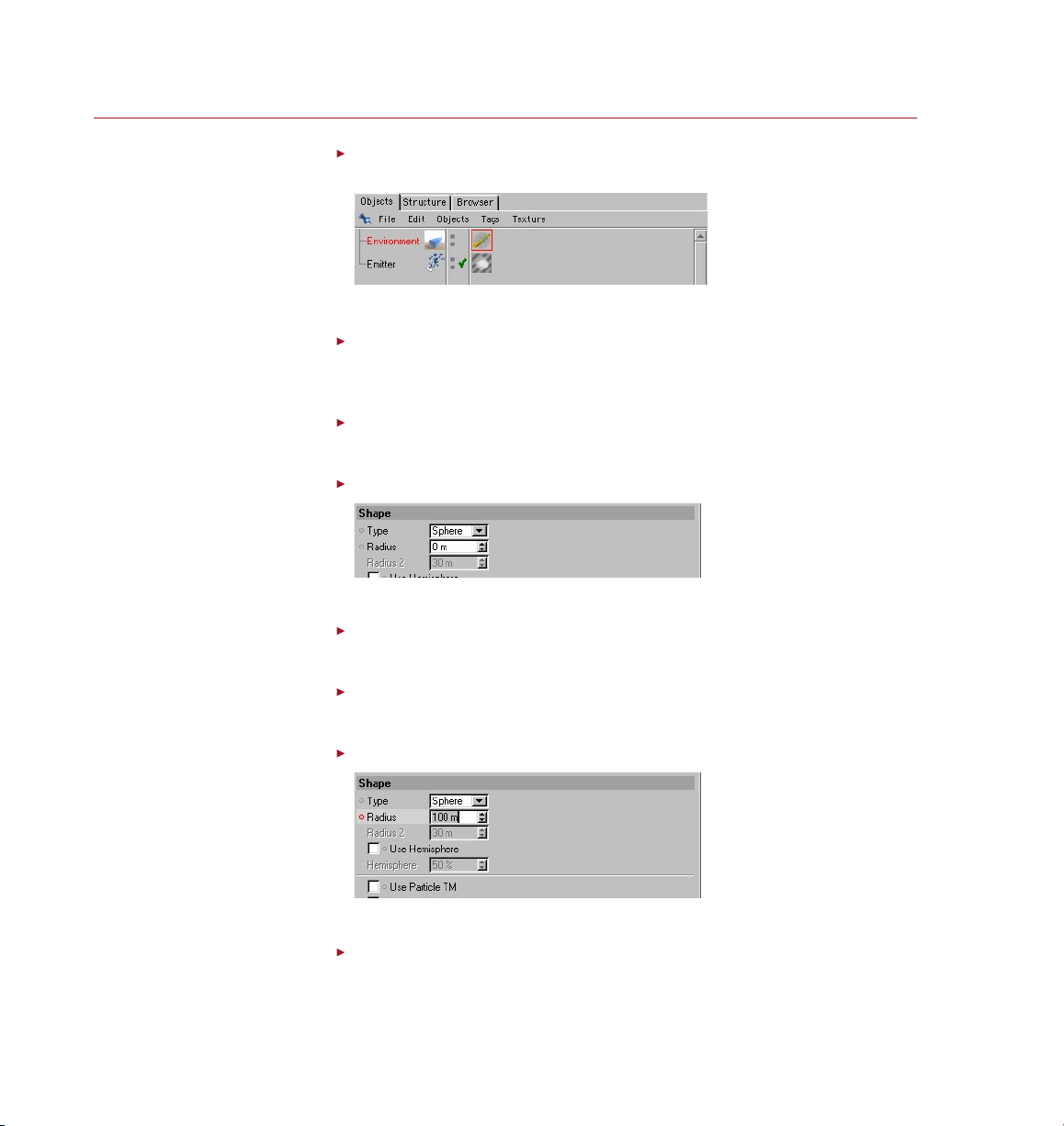
62 TUTO RIAL S
PYRO CLUST ER
As an Env ironm ent obj ect
encom passe s the ent ire sce ne,
apply ing a Volum eTracer to
it mean s that all P yroCluste r
effe cts in t he scen e are
controlled by t his Volum eTracer.
Here we a re dening our p uffs
to have no vo lume at all.
Drag the VolumeTracer material from the Material manager and drop it onto
the Environment object in the Object manager.
We have now completed the basic, minimum set-up for a PyroCluster effect.
In the Material manager, select the PyroCluster material by clicking on it
once.
This displays the PyroCluster material settings in the Attribute manager.
In the animation toolbar, ensure the time slider is at frame 0.
Our animation will begin at frame 0.
In the Attribute manager, on the Shape page, set Radius to 0.
Our PyroCluster puffs will begin life with no volume at all.
Ctrl-click on the circle next to Radius.
This records the current value of the Radius parameter in a keyframe at frame 0.
In the animation toolbar, drag the time slider to frame 90.
Our animation will end at frame 90.
In the Attribute manager, on the Shapes page, set Radius to 100.
A red cir cle to th e left o f a
parame ter name means that a
keyframe has been recorde d
for this parame ter but at some
frame ot her tha n the cur rent
one. A re d dot mea ns that a
keyframe has been recorde d at
the current frame.
Our PyroCluster puffs will grow to this size.
Ctrl-click on the Radius parameter name.
This records the current value of the Radius parameter in a keyframe at frame 90.
Page 71

PYRO CLUST ER
TUTOR IAL S 63
To make puffs visible in the
viewp ort, enable the Preview
option.
Still on the Shapes page, enable the Preview option.
This enables us to preview the animation of PyroCluster puffs in the viewport.
In the animation toolbar, press Play.
We can see that the particles start off small and become larger over time.
Summary
The vast majority of parameters for a P yroCluster material can be animated in this
way. You can animate any parameter that has a circle next to its name in the Attribute
manager or Material Editor. As this is regular CINEMA 4D keyframe animation,
anything you can do with a regular CINEMA 4D object can be done in exactly the
same way with PyroCluster puffs.
Page 72

Page 73

Index
Page 74

Page 75

PYRO CLUST ER
INDE X 67
A
Animating parameters 52
Attribute manager
Age page 29
Cylindrical Distance page 33
Distance page 31
Globals page 22
Illumination page 38
Noise page 46
Shadow page 42
Shape page 35
Auto rotation 36
B
Bias 49
Bump shading 39
C
Color
Age page 30
Cylindrical Distance page 34
Distance page 32
Globals page 25
Color Mix
Age page 30
Cylindrical Distance page 34
Distance page 32
D
Density 25, 27
gradient mode 27
Diffuse lighting 38
Display Result 17
E
Edit Alpha 17, 18, 21, 50
Emitter Direction 33
Emitter plane 31
F
Far Range
Cylindrical Distance page 33
Distance page 31
Flat Radius 23, 26, 27
G
Gain 49
Gradients
alpha channel 17
animating colors 19
birth and death of particles 18
contex t menu 17
interpolation 16
setting color s 18
using gradients 15
working with gradients 17
Gradient Mode 23, 26, 50
Grow Radius 47
H
Hidden Objects
rendering 11
High Thres. 49
I
Illumination 38, 39, 53
Installation 2
L
Lighting
bump shading 39
diffuse 38
including and excluding 53
ray angle 38
self illumination 39
Local Radius 26
Low Thres. 49
Luminosity 24, 30, 32, 34
M
Multiple use iii
N
Near Range
Cylindrical Distance page 33
Distance page 31
Network operation iii
Noise 46
color of 50
Detail 48
invert 51
types of 46
P
Parameters. See Attribute man-
ager
Parameter animation 52
Particle settings 18
Peak Blend 48
Phase 48
post ef fect. See VideoPost
Presets 28
Preview 23
in the viewport 37
R
RayTrans. Correction 13
Ray Angle lighting 38
Ray Bias 28
Ray Trans. Limit 10, 13
Registration 1
Regularity 47
Render Mode
in the Volume Tracer 12
on the Globals page 23
Rotate shapes 37
S
Scale
noise 47, 51
Scale shapes 37
in relation to velocity 37
Secrecy v
Shadows 42
including and excluding 53
Shadow Color Filter 14, 42, 44
Shape type 35
Shininess 40, 41
Speculars
shininess 40
soften 41
strength 40
Static Pos 50
Suppor t 2
T
Technical suppor t 2
Transfer iv
U
Using gradients 15
Page 76

68 INDEX
PYRO CLUST ER
V
VideoPost 23
Visible light. See Volume light
effects
Volume light effects 14
Volume Tracer 7, 8, 9, 11, 13, 39
W
World Radius 27
World Step Size 9, 10, 12
 Loading...