

MODEL NO. ______________
SERIAL NO. ______________
GENERAL INSTRUCTIONS
For the
INSTALLATION,
OPERATION and MAINTENANCE
of
DURAWATT EXR
WATER HEATERS
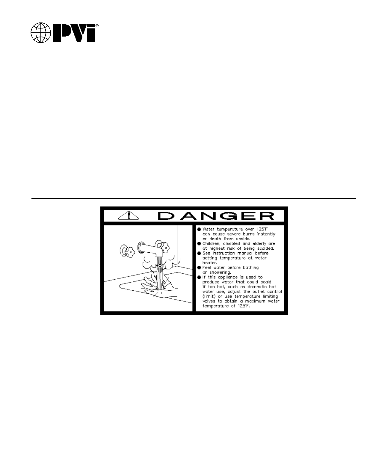
This water heater is equipped with an
adjustable thermostat to control water
temperature. Hot water temperatures
required for automatic dishwasher and
laundry use could cause scald burns
resulting in serious personal injury and/or
death. The temperature at which injury
occurs varies with the person’s age and
time of exposure. The slower response time
of disabled persons increases the hazards
to them. Never allow small children to use a
hot water tap or to draw their own bath
water. Never leave a child or disabled
person unattended in a bathtub or shower.
PV500-33 05-2002 1 Section 33
Since the thermostat temperature setting
could be set too high, adjust the thermostat
temperature setting to 125°F or lower.
Lower settings help reduce risk of scald
injury. Remember, no water heater system
will provide exact temperature at all times.
Allow a few days of operation at this setting
to determine the correct temperature
setting consistent with your needs and
remember, “Hotter water increases the risk
of scald injury.” Also, the water heater
should be located in an area where the
general public does not have access to set
temperatures.
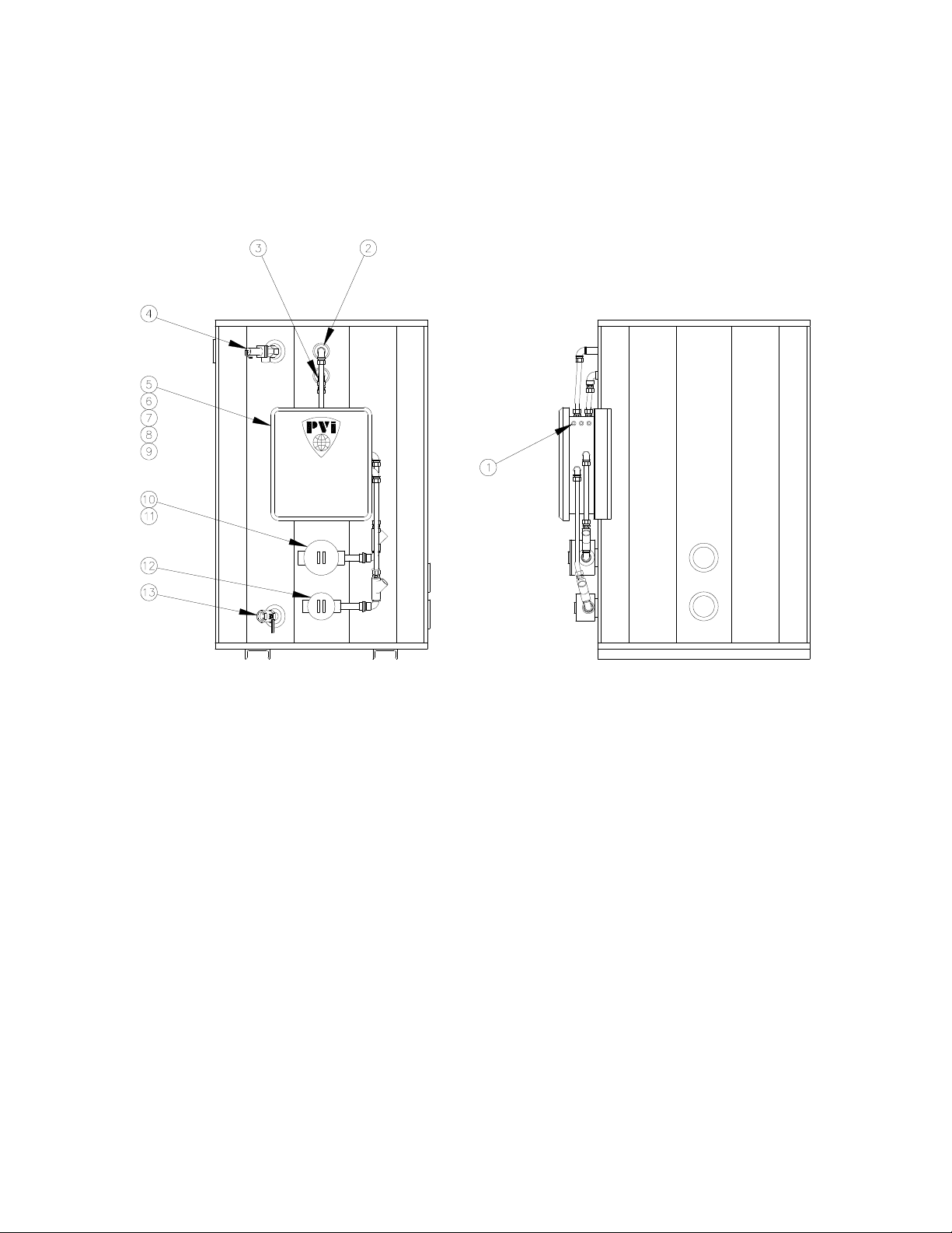
DURAWATT EXR WATER HEATER
TYPICAL CONSTRUCTION
Figure 33-1
1. Status lights 7. Fuses
(GRN-Power on; YEL-Elements on; 8. Contactors
RED-Over temp or low water 9. Step-down transformer (optional)
2. Float low water cutoff 10. Primary heating element (NEMA 7)
3. Temperature limiting device 11. Operating thermostat
(Set at 190°F) (Set at 120°F, adjustable from 80°F to 185°F)
4. Temperature & pressure relief valve 12. Secondary heating element (NEMA 7)
5. Control enclosure 13. Drain
6. Supply & remote signal connections
PV500-33 05-2002 2 Section 33

DURAWATT EXR WATER HEATER
ELECTRICAL CONNECTIONS
1. Check rating plate on water heater for correct voltage, phase and amperage. Refer to wiring
diagram for control component identification.
2. Use a proper wire size and branch circuit protection as required by the National Electrical Code
and state/local codes. PVI electric water heater specification sheets show number and size of
power connectors furnished with the heater for a minimum 90°C copper connecting wire.
3. Use correct size ground wire; attach to pressure connector marked “GR” inside the control
enclosure.
4. Connect supply feeders to distribution block inside the control enclosure. Conduit openings
have been provided for electrical connection and remote alarm circuitry as required. All holes
should be sealed with appropriate threaded hole plug if not used.
5. A float type low water cut-off switch has been provided to de-energize the heating circuit when
a low water volume is present.
STARTUP
1. Secure and lock-out electrical feed power circuit to water heater.
2. Check components to assure secure fit during transport and installation. Check wiring
connections in junction box for full contact and tight connection.
3. Inspect conduit seals between the control enclosure and heating element junction boxes to
ensure that they have been sealed.
4. Plumb water connections with appropriate shutoff valves, expansion tanks and check valves per
local plumbing codes.
5. With water outlet valve closed, open relief valve and water inlet valve, and fill tank with water
before turning on electricity. Dry energizing water heater immersion elements will burn out
elements rapidly and void the element warranty. When water exits relief valve, close relief valve
and continue to fill until tank is full.
6. Energize the main power circuit. Check power distribution to circuits with electrical meter to
assure proper power supply and operation. If improper readings are indicated, de-energize the
unit, disconnect the power lines to the unit and review wiring diagram for proper connection.
Check fuses to assure tight connection or any signs of failure.
7. To set the operating thermostat, remove the heating element junction box screw cover. (The
thermostat is located in one element housing only - check upper element first for thermostat
location.) A dial type thermostat has been selected for ease of use. Align desired temperature
(°F) with element temperature indicator mark and secure cover.
NOTE: The mercury displacement contactors are activated by a magnetic field and will make
some noise and vibration. This is normal.
PV500-33 05-2002 3 Section 33

DURAWATT EXR WATER HEATER
8. Open water outlet valve. Water heater is ready for operation. Heat up time will be dependent on
input and tank capacity.
9. After startup and with the water heater operating, allow the water in the tank to reach desired
temperature and the heating elements shut off. Draw hot water from a nearby outlet valve until
the heating elements energize. This will assure proper operation of the heating elements,
thermostat and other operating controls.
MAINTENANCE
1. A preventative maintenance program should be established to assure a long, trouble free life of
the water heater.
2. Flushing of the tank is recommended every two or three months, depending on water
conditions. To flush, disconnect (lockout) power to the unit. Open the drain valve and allow
water to flow through the tank until it runs clear. Close the drain valve. Draining two or three
gallons of water from the bottom of the tank on a weekly basis will also help prevent the
accumulation of sediment. A scale of lime will normally form on the heating elements and the
surface of the tank during heating cycles. The more hot water used, the more fresh water
containing the scale-forming elements are brought into the tank. As the temperature increases,
the rate of scale deposited will also increase. Sediment and scale accumulations in the tank will
greatly reduce the heating ability of the heater by reducing the effectiveness of the heat transfer
surfaces and can result in element failure.
3. Since PVI cannot control the use of the water heater, the water conditions or maintenance, the
warranty on the heating elements does not cover poor performance, structural failure or leaking
due to an excessive accumulation of scale.
4. The temperature and pressure relief valve should be checked at regular intervals. Open and
close the valve to insure proper operation. If the valve does not open or close properly when
tested, it must be replaced. Replace the relief valve with a like kind or one meeting the
requirements stated on the rating decal located on the valve.
WARNING: THE RELIEF VALVE IS A SAFETY DEVICE. DO NOT PLUG VALVE.
5. All electrical connections must be checked two weeks after startup to assure tightness. Heating
and cooling from operation can loosen connections. Every month, connections should be
inspected for any discoloration of wire terminal points.
6. The contactors are sealed and require no periodic maintenance other than checking wire
connections. These contactors contain MERCURY and must be returned directly to the
manufacturer for proper disposal. To return contactors, please call WATLOW CUSTOMER
SERVICE @507-454-5300 for a “Return Material Authorization” number. Mail the contactor
directly to the address provided by WATLOW CUSTOMER SERVICE for proper disposal.
Contact PVI @800-433-5654 to purchase the new contactor. Please have the water heater serial
number when ordering replacement contactors and the printed rating of the contactor to be
replaced.
7. Fuses for the load circuits are fast acting to prevent the contactor from rupturing in the event of
a heater short circuit. Replace with same type and rating.
PV500-33 05-2002 4 Section 33
 Loading...