


INSTALLATION & MAINTENANCE MANUAL
TURBOPOWER® 99 GAS WATER HEATER
MODELS: (742, 1485, 2228, 2971) N, P, L, SS (330, 425, 600, 950, 1200) A-TP
Installation and service must be performed by a qualified service installer, service agency or the gas supplier.
IMPORTANT: THIS MANUAL CONTAINS INFORMATION REQUIRED FOR INSTALLATION, OPERATION AND MAINTENANCE OF THIS EQUIPMENT. READ AND FOLLOW THE INFORMATION IN THIS MANUAL AND ALL OTHER PROVIDED INSTRUCTIONS, LABELS AND MARKINGS BEFORE INSTALLING, OPERATING OR SERVICING THIS UNIT.
TO THE INSTALLER: After installation, these instructions must be given to the equipment user or left near the appliance.
SPECIAL INSTRUCTIONS TO THE OWNER: Retain this manual for future reference. These instructions contain important information that will help you in maintaining and operating this appliance.
PVI INDUSTRIES, LLC - Fort Worth, Texas 76111 - www.pvi.com - Phone 1-800-433-5654
1 |
PV500-12 08/12 |
TURBOPOWER 99 WATER HEATER
TABLE OF CONTENTS
1.Safety Considerations
2.Product Descriptions
3.Standard Features and Equipment
3.1Warranty
4.Water Heater Installation
4.1Checking Equipment Before You Install
4.2Codes
4.3Electrical Requirements
4.4Location
4.5Installation
4.6Service Clearances
4.7Clearances to Combustible Surfaces
5.Condensate Neutralization & Disposal
6.Combustion and Ventilation Air
7.Vertical and Horizontal Remote Air
7.1Vertical or Horizontal Remote Air Option
7.2Remote Air Piping Design
7.3Maximum Allowed Combustion Air Vent Length (Equivalent Length)
7.4Remote Air Piping of Multiple Units
8.Venting Products of Combustion
8.1Vent System Design
8.2Venting of Multiple Units
8.3Maximum Allowed Vent Length (Equivalent Length)
8.4Vent Construction and Assembly
8.5Horizontal and Vertical Venting Through a Wall or Roof
9.Gas Supply and Piping
9.1Inlet Pressure
9.2Manifold Pressure
9.3Gas Piping Size
9.4Appliance Isolation during Gas Supply Piping Pressure Test
9.5Gas Connection
9.6Gas Train and Controls Certification
9.7Gas Control Trains
10.General Information
10.1Temperature and Pressure Relief Valve(s)
10.2Upper LED Readout
10.3High Water Temperature Limit Control
10.4Cathodic Protection
10.5Thermal Expansion
11.TempTrac Electronic Controller Panel
11.1Principle of Operation
11.2Lower LED Readout
11.3Upper LED Readout
11.4Control Buttons
11.5To View the Setpoint
11.6To Change the Setpoint
11.7To Change Other Parameters
11.8LED Display Alarm Messages
12.Remote Connections – Terminal Strip
13.Start-up Procedure
14.Periodic Maintenance
15.Diagrams
Warranty forms ship separately with each product.
2 |
PV500-12 08/12 |

TURBOPOWER 99 WATER HEATER
1 SAFETY CONSIDERATIONS
WARNING: If the information in the supplied manual(s) is not followed exactly, a fire, explosion or exposure to hazardous materials may result, causing property damage, personal injury or loss of life.
FOR YOUR SAFETY
Do not store or use gasoline or other flammable vapors or liquids in the vicinity of this or any other appliance.
WHAT TO DO IF YOU SMELL GAS
Do not try to light any appliance.
Do not touch any electric switch; do not use any phone in your building.
Immediately call your gas supplier from a location away from your building and the smell of gas. Follow the gas supplier's instructions.
If you cannot reach your gas supplier, call the fire department.
Installation and service must be performed by a qualified installer, service agency or the gas supplier.
This product contains, or may come to contain materials that have been identified as carcinogenic, or possibly carcinogenic to humans. Before installing, servicing or removing this product, read and follow the supplied instructions
WARNING: Installation and service must be performed by a qualified installer, service agency or the gas supplier, who must read and follow the supplied instructions before installing, servicing or removing this appliance. Refer to the information contained in this manual. Improper installation, adjustment, alteration, service or maintenance can cause property damage, personal injury, exposure to hazardous materials or loss of life.
WARNING: Do not use this appliance if any part has been under water. Immediately call a qualified service technician to inspect the unit and to replace any part of the control system, all gas controls and all other items affecting safe appliance operation and which has been under water.
WARNING: In an emergency shut the main gas supply valve to the appliance from a location safely away from the emergency. Failure to follow these instructions can cause property damage, personal injury, and exposure to hazardous materials or loss of life.
PRODUCT SAFETY INFORMATION
REFRACTORY CERAMIC FIBER PRODUCT WITH CRYSTALLINE SILICA
WARNING: This product contains or may come to contain crystalline silica, which has been identified by the International Agency for Research on Cancer (IARC) as carcinogenic to humans. This product also contains refractory ceramic fibers, which have been identified by the IARC as possibly carcinogenic to humans. Avoid breathing fiber particulates and dust.
RISKS:
Air borne fibrous insulation is a possible cancer hazard by inhalation.
Airborne crystalline silica may cause silicosis (lung disease) by inhalation.
May cause temporary irritation to eyes, skin, and respiratory tract.
PRECAUTIONARY MEASURES:
Minimize airborne fibers with engineering controls.
Use NIOSH/MSHA approved respirators as required (see MSDS).
Wear long sleeved, loose-fitting clothing, eye protection and gloves.
FIRST AID MEASURES: (If any of the irritations listed persists, seek medical attention)
|
Eyes: |
Flush with water. |
|
Skin: |
Wash with soap and warm water. |
Ingestion: Do not induce vomiting. Get medical attention if gastrointestinal symptoms develop.
Inhalation: Remove to fresh clean air.
WARNING: If you are unfamiliar with the safe handling of refractory ceramic fiber products, or if you wish additional information prior to beginning any disassembly of the water heater or boiler that might expose refractory ceramic fiber materials, contact: Unifrax Corporation, 2351 Whirlpool Street, Niagara Falls, NY 14305-2413, 1-800-322-2293.
IDENTIFICATION OF REFRACTORY CERAMIC FIBER MATERIALS (RCF):
The burner, lower tank and upper and lower flue collector assemblies utilize RCF material. (The RFC materials are located within the product and not generally exposed except during service, disassembly or assembly.)
3 |
PV500-12 08/12 |
TURBOPOWER 99 WATER HEATER
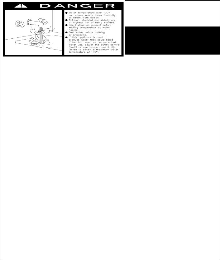
IMPORTANT SAFETY NOTE
It takes only 5 seconds of skin contact with 140°F water to cause a second degree burn! You must protect against high water temperatures at all
lavatories, tubs, showers and other points of hot water contact.
Accidental scalding from high water temperatures is a greater risk in some types of installations. Some examples are:
HOMES FOR THE MENTALLY HANDICAPPED
HOMES FOR THE PHYSICALLY HANDICAPPED
HOSPITALS AND NURSING HOMES
ELDER CARE FACILITIES AND REST HOMES
ORPHANAGES AND CHILD CARE FACILITIES
OTHER INSTALLATIONS - WHERE RESPONSE TO CONTACT WITH HOT WATER MAY BE SLOWER OR WHERE THE DANGER OF HOT WATER CONTACT IS GREATER
Thermostatically controlled mixing valves
must be used in the design of the potable hot water system.
Potable hot water should be tempered to no more than 110°F when used for bathing or other personal uses.
Good engineering practice mandates the use of thermostatically controlled mixing valves set at 120°F or less to keep the delivered water temperature below scalding temperatures.
4 |
PV500-12 08/12 |

TURBOPOWER 99 WATER HEATER
2 PRODUCT DESCRIPTION
1. |
Flue stack * |
9. |
Burner |
2. |
Fixed temperature high limit device |
10. |
Upper flue collector |
3. |
Adjustable temperature limit device |
11. |
Lower flue collector |
4. |
Digital operating temperature control |
12. |
Rear module access (optional on some models) |
5. |
Control switch(s) and fuse(s) |
13. |
Condensate neutralization system |
6. |
Gas valve |
14. |
Condensate drain (must be plumbed to floor drain) * |
7. |
Gas inlet |
|
|
8. |
Drip leg |
|
(* Not furnished by PVI) |
5 |
PV500-12 08/12 |
TURBOPOWER 99 WATER HEATER
3 STANDARD FEATURES AND EQUIPMENT
3.1Warranty
Factory warranty does not cover improper installation or operation. (See warranty for complete details). Warranty exclusions include but are not limited to failure or malfunctions resulting from:
1.Failures to properly apply, install, operate, or maintain the appliance in accordance to printed instructions.
2.Abuse, alteration, accident, fire, flood and the like.
3.Sediment or lime buildup, freezing or any other conditions causing inadequate circulation.
4.Corrosive or contaminated atmosphere.
4 WATER HEATER INSTALLATION
4.1Checking Equipment Before You Install
Inspect the unit completely upon receipt from the freight carrier before signing the bill of lading. Inspect the appliance and all accompanying parts for signs of impact or mishandling. Verify the total number of pieces shown on packing slips with those actually received. Contact the freight carrier immediately if any damage or shortage is detected.
4.2Codes
The equipment shall be installed in accordance with those installation regulations in force in the local area where the installation is to be made. These shall be carefully followed in all cases. Authorities having jurisdiction shall be consulted before installation is made. In the absence of such requirements, the installation shall conform to the latest edition of the National Fuel Gas Code, ANSI Z223.1. Where required by the authority having jurisdiction, the installation must conform to American Society of Mechanical Engineers Safety Code for Controls and Safety Devices for Automatically Fired Boilers, No. (CSD-1). All appliances conform to the applicable sections of the latest edition of ASME Boiler and Pressure Vessel Code, Section IV. Where required by the Canadian authority having jurisdiction, the installation must comply with CAN/CSA B149 and/or B149.2 and/or provincial regulations.
4.3Electrical Requirements
WARNING: Turn off all electrical service to the appliance when accessing the controls located inside the control cabinet. The cabinet contains high voltage wiring and terminals. If the electrical service is not turned off and these wires or terminals are touched, a dangerous shock causing personal injury or loss of life could occur. Close the control cabinet before restoring electrical service to the appliance.
See product specification sheets and/or appliance labeling for branch service requirements. The appliance, when installed, must be electrically grounded in accordance with the requirements of the authority having jurisdiction or in the absence of such requirements, with the latest edition of the National Electrical Code ANSI/NFPA No. 70. When the unit is installed in Canada, it must conform to the CSA C22.1, Canadian Electrical Code, Part 1 and/or Local Electrical Codes.
1.All wiring between the unit and field installed devices must be made with type T wire.
2.Line voltage wire exterior to the appliance must be enclosed in approved conduit or approved metal clad cable.
3.To avoid serious damage, DO NOT energize the unit until the system and appliance is full of water.
4.4Location
These units are suitable for indoor installation only.
1.Locate the unit so that if water connections should leak, water damage will not occur. When such locations are unavoidable, install a suitable drain pan, and plumb pan to ensure adequate drainage in the event of a leak. Under no circumstances is the manufacturer responsible for water damage in connection with this unit, or any of its components. The manufacturer’s warranty does not cover water damage.
2.Protect associated electrical components and electrical connections from water (dripping, spraying, rain, etc.) during appliance operation and service.
6 |
PV500-12 08/12 |
TURBOPOWER 99 WATER HEATER
3.Place the appliance on a level, non-combustible floor. Concrete over wood is not considered noncombustible.
4.Do not install on carpet or other combustible floor coverings.
5.Installation over a combustible floor: Units installed over a combustible floor MUST be provided with a base of hollow clay tile or concrete blocks from 8" to 12" thick and extending 24" beyond the sides. Place the blocks in line so that the holes line up horizontally to provide a clear passage through the blocks. Install 1/2” fireproof millboard with a 20-gage sheet metal cover over the block base. Center the unit on the base. Also follow this procedure if electrical conduit runs through the floor, and beneath the appliance. A field-installed base must meet all local fire and safety code requirements.
4.5Installation
WARNING: Use industry standard safe rigging methods when attempting to lift or move this product. Failure to follow these instructions could result in property damage, serious injury or death. One common method includes the use of straps and spreader bars, lifting from the water heater base skid assembly.
1.Check the data decal on the appliance. Be sure the electrical, water, oil, or gas supply is adequate for the installation.
2.Carefully remove all shipping supports and bracing.
3.Use only non-ferrous water piping and fittings. Do not use galvanized pipe or fittings. Use of ferrous or galvanized pipe or fittings can cause rust to form.
4.Install shut-off valves and unions on the inlet and outlet water piping for servicing. Use caution when threading pipe nipples into tank connections to prevent cross threading, or over-tightening. Always use a back-up wrench on tank nipples when tightening unions, valves, etc.
5.Insulate hot water and return circulation lines. Insulate cold water supply lines if subject to freezing during shutdown periods. IMPORTANT: Do not use the plumbing connected to the appliance as a ground for welding or any other purpose.
6.Pipe the drain valve to a suitable open drain.
4.6Service Clearances
Allow sufficient space to provide adequate clearances on all sides for service and inspection. Recommended clearance is 24” at the top and front, 18” at left and right sides of the appliance. Optional equipment may increase the clearance requirements. Allow sufficient space for installing and servicing connections such as water, gas, vent, combustion air, electrical, pump and other auxiliary equipment.
4.7Clearances to Combustible Surfaces
The appliance must not be installed on a combustible floor, on carpet, on other combustible floor coverings or on a non-combustible floor covering combustible material. The minimum clearance to unprotected combustible material is 6” from the front, top, left and right sides of the burner and flue collector. Combustible materials are allowed to contact the tank sides and top, however service clearances are recommended.
7 |
PV500-12 08/12 |
TURBOPOWER 99 WATER HEATER
5CONDENSATION NEUTRALIZATION AND DISPOSAL
The TURBOPOWER® 99 condensing water heater will produce significant amounts of condensate because of its high efficiency. Condensate occurs naturally when water vapor in combustion gases is cooled below the dew point. Although only slightly acidic, the condensate is routed through a condensate neutralization system to become lower the pH, allowing for disposal into a drain or sewer system.
The supplied condensate neutralization system contains a crushed limestone neutralization bath. Condensate slowly flows through a crushed limestone bed and is neutralized, thus avoiding chemical treatment or dilution using substantial quantities of tap water. Over time the limestone is consumed by this process and must be replaced. Periodically test the condensate with a pH meter or pH paper and if lower than 5, the crushed limestone must be replaced. If no condensate is observed, the main pipe containing the crushed limestone should be inspected for blockage.
If the heater is not installed on a housekeeping pad to ensure gravity drainage, a means of removing condensate, such as a pump, will be required. The neutralization bath and condensate trap are filled with condensate (water), even when the heater is not running. Therefore, protection must be provided to the neutralization bath, the condensate trap and to the condensate drain path, so that condensate does not freeze and damage parts or block condensate flow.
6COMBUSTION AND VENTILATION AIR
Provisions for adequate combustion and ventilation air to the mechanical room must be in accordance with the “Air for Combustion and Ventilation” section in the latest edition of the National Fuel Gas Code, ANSI Z223.1 and/or CAN/CSA B149, Installation Codes or applicable provisions of the local building codes.
Equipment located in confined spaces requires two openings installed within 12” (300 m) from the top and bottom of the room to assure adequate combustion air and proper ventilation. The total input of all gas utilization equipment installed in the room must be used to determine the required minimum air volume needed for combustion, ventilation and dilution of flue gasses.
1.All Air From Outdoors:
a.Each opening requires a minimum free area of 1 square inch per 4000 Btu/hr input if directly communicating with the outdoors or communicating to the outdoors through vertical ducts.
b.Each opening requires a minimum free area of 1 square inch per 2000 Btu/hr input if communicating with the outdoors through horizontal ducts.
2.All Air From Inside The Building:
Each opening requires a minimum free area of 1 square inch per 1000 Btu/hr input, but not less than 100 square inches (0.06 m2).
3.Combination Of Air From The Indoors And From The Outdoors:
Refer to National Fuel Gas Code, ANSI Z223.1 and/or CAN/CSA B149, Installation Codes or applicable provisions of the local building codes.
NOTE: This unit may be installed with an optional remote air intake system which uses a make-up air duct to draw combustion air directly from outdoors. (See Vertical and Horizontal Remote Air Section.)
WARNING: Adequate clean combustion air must be provided to the appliance. Under no circumstances should the appliance ever be under a negative pressure. Particular care should be taken when exhaust fans, compressors, air handling units, etc. may rob air from the appliance. The combustion air supply must be completely free of any chemical or fumes, which may be corrosive to the appliance. Some common chemical fumes to avoid are fluorocarbons and other halogenated compounds, most commonly present as refrigerants or solvents, such as Freon, trichloroethylene, perchlorethylene, chlorine, etc. These chemicals, when in contact with the equipment or when burned, form acids which quickly attack the tubes, flue collector, stack and other appliance and auxiliary equipment. The result of inadequate clean combustion air or negative pressure can be premature unwarranted product failure or unsafe operation producing carbon monoxide that could escape into the building. Exposure to carbon monoxide can lead to injury or death.
8 |
PV500-12 08/12 |
 Loading...