

Page 1
INSTALLATION & MAINTENANCE MANUAL FOR
QuickDraw
INSTANTANEOUS
ENERGY: WATER TO WATER
U-TUBE SINGLE-WALL & DOUBLE-WALL HEAT EXCHANGERS
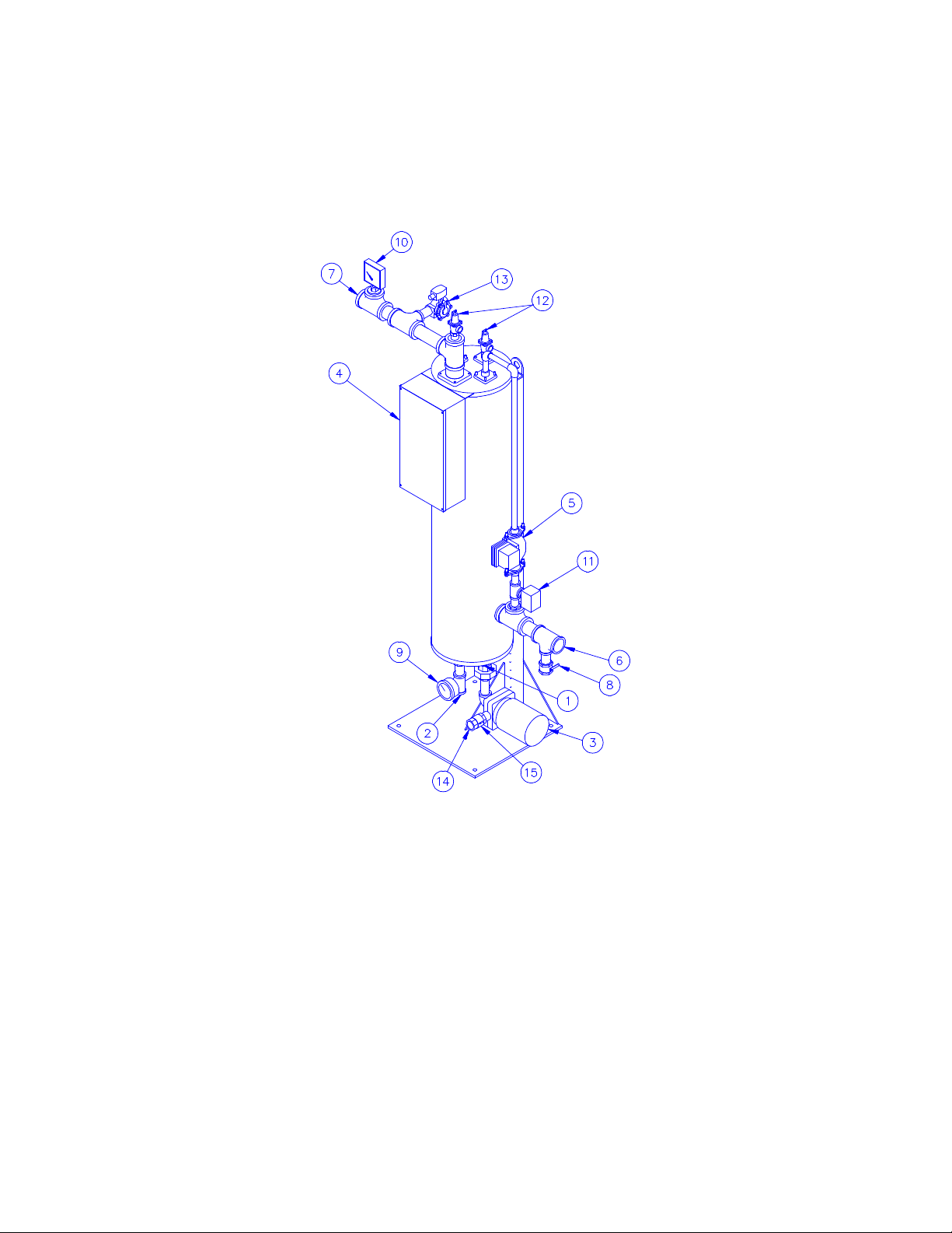
TYPICAL CONSTRUCTION
FIGURE 24-1
1. U-tube Heat Exchanger 9. Boiler Water Temperature Gauge *
2. Boiler Water Inlet 10. Tridicator *
3. Boiler Water Pump 11. Flow Switch *
4. Control Enclosure 12. Relief Valve (AGA optional)
5. Intratank Circulator 13. Tank Purge Valve *
6. Potable Water Inlet 14. Boiler Water Outlet
7. Potable Water Outlet 15. Check Valve
8. Tank Drain * Optional
CAUTION: TEMPERATURES HIGHER THAN 125°F. INCREASE THE RISK OF SCALD INJURY!
IMPORTANT: Clearances for servicing and inspection are 18” at top, sides and rear and a
minimum of one tank diameter in front.
PV500-24 03-99 Section 24 1
Page 2

QuickDraw
WATER WITH SINGLE-WALL / DOUBLE-WALL
START-UP OPERATION
1. The boiler water circulating pump has
been selected to provide optimum flow
through the heat exchanger tubes to
meet demand with the available boiler
water. The pump is controlled by the
thermostat and draws from the
operating boiler water loop. When the
demand is satisfied, the pump stops,
causing the boiler water to bypass the
CAUTION: Temperatures higher than 125°F. increase the risk of scald injury.
unit. In addition, the water heater maybe
equipped with a continuous operation
tank circulation pump. The boiler water
circulation pump is sized to satisfy all of
the head resistance of the heat
exchanger, therefore no pressure drop
need be considered for this unit in sizing
primary loop pumps.
START-UP PROCEDURE
1. Fill the tank with water; open the relief
valve or a nearby hot water outlet to
purge air from the top of tank. Check for
plumbing leaks.
2. Push the control switch to “on” position.
Check boiler water pump operation. The
tank circulating pump should also
operate. Check thermostats for proper
setting. The thermostats are labeled as
to their function. The temperature
limiting device is set at 200°F.
Temperature Setting: The thermostats
are set at the factory to 120°F on the
operating control. Upon startup, the
factory preset operating temperature is
visible on the LED indicator of the digital
controller. Adjust the temperature using
the appropriate up and down arrow keys
on the face of the controller. A slight
variance in temperature control may be
noticed as the digital control tunes,
allow time for the temperature to
stabilize.
3. Open nearby hot water tap to maintain a
flow of water through the tank when
starting up units. Regulate flow of water
through the tank to allow the boiler
water pump to cycle off and on, and
check operation of unit.
PV500-24 03-99 Section 24 2
Page 3

QuickDraw
WATER WITH SINGLE-WALL / DOUBLE-WALL (con't)
ELECTRICAL
The heater is wired for 120 volts and must be electrically grounded in accordance with local
codes, or in the absence of local codes, with the latest edition of the National Electrical Code
ANSI/NFPA. When unit is installed in Canada, it must conform to the CSA C22.1, Canadian
Electrical Code, Part 1 and/or local electrical codes.
1. Water must be pumped continuously
through the boiler when it is being fired.
2. Do not energize water heater or pumps
until tank is full of water. Serious
damage may result.
NOTE: Use only copper wire of proper sizing for incoming service. Damage
resulting from use of aluminum wiring will be excluded from coverage under
the warranty of this unit.
RELIEF VALVE PIPING
The water heater is supplied with a
pressure and temperature relief valve, sized
in accordance with ASME requirements.
Each relief valve should be piped to a
MAINTENANCE
1. A preventive maintenance program
should be established to assure a long,
trouble-free life for the water heater.
2. Scale will normally form in the tank
during operation and will accumulate on
the bottom of the tank. The scale is
formed from the natural chemicals in the
water that precipitate out during the
heating cycles. Some water supplies
contain more of these chemicals than
others, and the scale buildup will occur
3. All wiring must be in accordance with all
local, state, or federal codes.
4. Provide proper overload protection for
the system's circulating pumps.
suitable floor drain. No reducing coupling or
other restriction can be installed in the
discharge line.
more rapidly. Other factors affecting the
scale buildup are the amount of hot
water used and the temperature of the
water. The more hot water used, the
more fresh water containing the scaleforming chemicals is brought into the
tank. As the temperature of the water
increases, the rate of scale deposited
will be increased. The unit should be
inspected and cleaned as required by
local water conditions.
PV500-24 03-99 Section 24 3
Page 4

QuickDraw
WATER WITH SINGLE-WALL / DOUBLE-WALL (con't)
WARNING: Make sure valve is piped to a
proper drain per instructions. Scalding
injury and/or water damage can occur
from either the manual lifting of the lever
or the normal operation of valve if it is
not piped to a proper drain. Insure that
the safety relief valve piping is of the
proper material and rating for the
temperature and pressure of the system
and that it is secured to prevent possible
injury. If valve fails to flow water or
reseat, consult the factory.
CAUTION: The relief valve is a primary
safety device.
Since PVI cannot control the use of the water heater, water conditions, or maintenance,
the warranty on the water heater does not cover poor performance, structural failure, or
leaking due to an excessive accumulation of scale.
3. The temperature limiting device and
thermostat sensors that extend into the
water in the tank may become coated
with scale, depending on the type of
water in your area. This coating will
affect the accuracy of the sensors and
can allow the water temperature to
exceed the desired limits. They should
be removed from the tank and inspected
at intervals. Remove scale if present.
CAUTION: On control systems using 120
volt external power, be certain switch
is off, and power disconnected to
avoid electrical shock before work is
performed on this heater.
PV500-24 03-99 Section 24 4
 Loading...