

Page 1
C280 / S280
C310 / ST310
OWNER’S MANUAL
FISHING BOATS
3901 St. Lucie Blvd.
Ft. Pierce, Florida 34946
© 2010 S2 Yachts, Inc.
Part Number 9213007
May 2011
C280 / S280 / C310 / ST310
Page 2

Safety Information
Your Owner’s Manual was written to include
safety instructions to ensure safe operation
and maintenance of your boat. Safety alerts
symbols are used to alert potential personal
injury hazards.
! DANGER
Indicates a hazardous situation which, if
not avoided, will result in death or serious injury.
! WARNING
Indicates a hazardous situation which, if
not avoided, could result in death or
serious injury.
All instructions are viewed from the stern looking toward the bow, with starboard (to your
right) and port (to your left). A glossary of boating terms is included.
Your boat produces carbon monoxide (CO)
and uses flammable fuel. CO will cause
BRAIN DAMAGE or DEATH. Carbon monoxide gas (CO) is colorless, odorless and
extremely dangerous.
Every precaution has been taken by Pursuit
Fishing Boats to reduce the risks associated
with death, possible injury and damage from
fire or explosion. Your own precaution and
good maintenance procedures are necessary
in order to enjoy safe operation of your boat.
! DANGER
Exposure to carbon monoxide will
cause death or serious injury. Avoid
direct and prolonged exposure to CO.
! CAUTION
Indicates a hazardous situation which, if
not avoided, could result in minor or
moderate injury.
! NOTICE
Indicates a potentially hazardous situation which, if not avoided, may result in
property damage.
Gasoline and other fuels are extremely
flammable and highly explosive under
certain conditions.
• DO NOT smoke or allow open flame
or sparks nearby when fueling.
• DO NOT block fuel vents.
• DO NOT store fuel in any containers
or compartments which are not designated for storing fuel.
Page 3

Table of Contents
Safety Information
Specifications ............................ 1-18
Boat Information ........................... 19
Warranty and Warranty
Registration Cards ....................... 20
Federal Boat Safety Act ............... 20
Product Changes ......................... 20
Transferring the Warranty .......... 20
Owner/Operator Responsibilities 20
Propulsion Systems
1.1 General ........................................ .... ... ... 1-1
1.2 Saltwater Application ........................... 1-1
1.3 Engine Lubrication ............................... 1-2
1.4 Engine Cooling System ....................... 1-2
1.5 Propellers ................................. ... .... ... ... 1-2
1.6 Engine Instrumentation ....................... 1-3
Helm Systems
Electrical Systems
4.1 General .................................................. 4-1
4.2 DC System ............................................. 4-1
4.3 Main Breakers ...................................... 4-3
4.4 12-Volt DC Panels Helm ....................... 4-4
4.5 AC System ............................................ 4-6
4.6 AC Main Distribution ............................ 4-6
4.7 Battery Charger Operation ................... 4-7
4.8 Shore Power Connection ..................... 4-7
4.9 Electrical System Maintenance ........... 4-8
4.10 General Precautions .......................... 4-9
Plumbing System
5.1 Fresh Water System ............................. 5-1
5.2 Raw Water Washdown .......................... 5-1
5.3 Livewell .................................................. 5-2
5.4 Drainage ................................................ 5-3
5.5 Plumbing System Maintenance ........... 5-4
2.1 General .. ... ... ... ... .... ................................ 2-1
2.2 Engine Throttle and Shift Controls ..... 2-1
2.3 Neutral Safety Switch .......................... 2-1
2.4 Engine Power Tilt and Trim ................. 2-2
2.5 Engine Stop Switch .............................. 2-2
2.6 Steering System ... ... ... ... .... ... ... ... .... ... ... 2-3
2.7 Trim Tabs .... ... ... .... ... ... ... .... ... ... ... .......... 2-3
2.8 Compass ........ ... .... ... ... ... .... ... ... ... .... ...... 2-4
2.9 Spotlight (Optional) ........................... ... 2-4
2.10 Control Systems Maintenance .......... 2-4
Fuel Systems
3.1 General .. ... ... ... ... .... ................................ 3-1
3.2 Fuel System ............ ... ... .... ................... 3-1
3.3 Fuel Management . ... ... ... .... ... ... ... .... ... ... 3-2
3.4 Fueling Instructions .. ... .... ...... ... .... ... ... 3-4
Ventilation System
6.1 Head Compartment Ventilation ........... 6-1
6.2 Carbon Monoxide and Proper
Ventilation ............................................. 6-1
6.3 Bilge Compartment Ventilation ........... 6-1
6.4 Maintenance .......................................... 6-1
Exterior Equipment
7.1 Deck ....................................................... 7-1
7.2 Cockpit ................................................... 7-2
7.3 Tower (Dealer Installed) ....................... 7-5
Interior Equipment
8.1 Head Compartment .............................. 8-1
8.2 Audio and Video Systems ................... 8-1
C280 / S280 / C310 / ST310
Page 4

Table of Contents
Safety Equipment
9.1 General ........................................ ... ... .... 9-1
9.2 Engine Alarms .. ... ... .............................. 9-1
9.3 Neutral Safety Switch ........................... 9-1
9.4 Engine Stop Switch .............................. 9-1
9.5 Automatic Fire Extinguishing System
(with Optional Generator) ................... 9-2
9.6 Carbon Monoxide Hazards ................. 9-2
9.7 First Aid ................................................. 9-5
9.8 Required Safety Equipment ................. 9-5
9.9 Additional Safety Equipment ............... 9-8
Operation
10.1 General .............................................. 10-1
10.2 Homeland Security Restrictions ..... 10-1
10.3 Rules of the Road ............................. 10-2
10.4 Pre-Cruise Check .............................. 10-3
10.5 Operating your Boat ......................... 10-4
10.6 Fishing ............................................... 10-6
10.7 Tower Operation (Dealer
Installation) ....................................... 10-6
10.8 Docking, Anchoring and Mooring ... 10-7
10.9 Controls, Steering or Propulsion
System Failure ..... .... ........................ 10-8
10.10 Collision ......................................... 10-9
10.11 Grounding, Towing and
Rendering Assistance .................. 10-9
10.12 Flooding or Capsizing ................... 10-9
10.13 Transporting your Boat ............... 10-10
10.14 Trailering your Boat .................... 10-10
10.15 Water Skiing ................................. 10-11
10.16 Man Overboard ............................ 10-12
10.17 Trash Disposal ............................. 10-12
Routine Maintenance
11.1 General ............................................. 11-1
11.2 Exterior Hull and Deck .................... 11-1
11.3 Seats, Upholstery, Canvas and
Enclosures ....................................... 11-5
11.4 Cabin Interior ................................... 11-6
11.5 Bilge .................................................. 11-6
11.6 Generator (Optional) ....................... 11-6
Seasonal Maintenance
12.1 Storage and Lay-up ......................... 12-1
12.2 Winterizing ....................................... 12-2
12.3 Recommissioning ........................... 12-4
Apendixes
Glossary of Terms ........................ A-1
Maintenance Schedule ................. B-1
Maintenance Log .......................... B-2
Boating Accident Report .............. C-1
Float Plan ....................................... D-1
Troubleshooting Guide ................ E-1
Schematics ..................................... F-1
C280 / S280 / C310 / ST310
Page 5
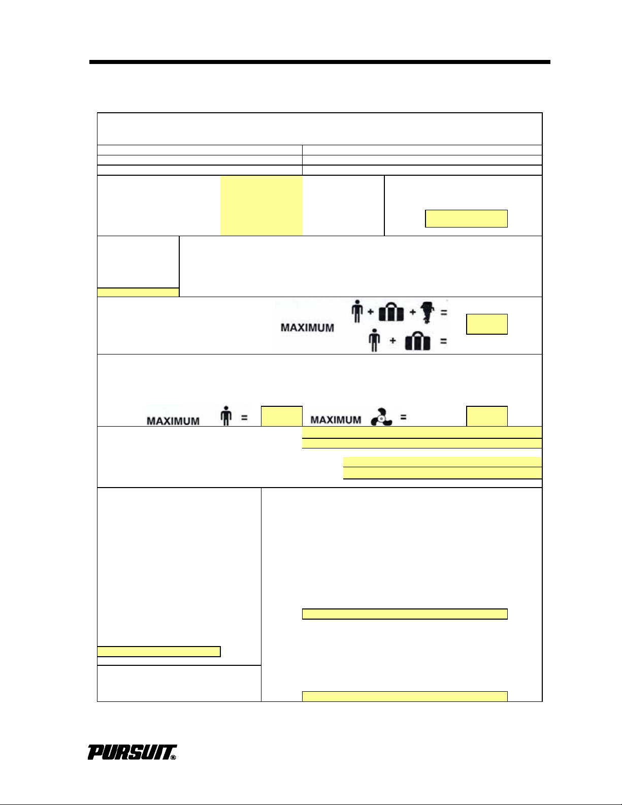
Specifications
C-Inshore Propulsion Type: Tipo di propulsione:
C-
à proximité de la côte
A
ntriebsart: Tipo de propulsión:
C-Costera Type de propulsion: Tipo propulsão:
C-Küstennane
Gewässer
C-Costeira
C-Perto da Costa
Intended Use:
Verwendungszweck: Hull Identification Number:
Usage prévu: Rumpfunner:
Utilizzo previsto: Nemero d'identification de coque:
Uso previsto: Nemero identificazione scafo:
Utilização: Numero de Identificacion del Casco:
Número de Identificação do Casco:
Maximum Recommended Load:
Charge maximale recommandée:
Carga Máxima recomendada:
Empfohiene Beladung Maximum:
Carico massimo ammesso:
Carga Máxima Recomendada:
Recommended Number of Persons: Maximum Rated Engine Power:
Nombre de personnes recommandé: Puissance nominale maximale du moteur:
Número recomendado de personas: Potencia máxima del motor:
Empfohlene Personenanzahl: Maximale Motorleistung:
Omologazione al trasporto di n. persone: Massima potenza nominale motore:
Número de Pessoas Recomendado: Máxima potência nominal do motor:
Engine Installed, Manufacturer, Model and Number(s):
Moteur installé, Fabricant, modèle et numéros(s):
Motor instalado, Fabricante, modelo y numero(s):
Motor instaliert, Hersteller, modell, nummer(en):
1.
Motore istallato, Costruttore, modello e numero(s): 2.
Motor Instalado, Fabricante, Modelo e Número(s):
Mass of Craft (Approximate) With Largest Equipped Engine and permanently attached items,
Masses de Navire (Approximatives) plus full water and fuel, plus maximum recommended load:
Peso de la embarcación (aproximado) Avec le plus grand moteur équipé et systèmes en liaison
Gewicht des Bootes (Nährungswert) permanente, plus pleine charge d'eau et de carburant, plus
Massa dell'imbarcazione (approssimativa) charge maximale recommandée:
Massa da Embarcação (Aproximada) Con el mayor motor equipado y elementos permanentemente
With Largest Equipped Engine and instalados, más combustible y aqua, más la carga máxima recomendada:
permanently attached items: Mit größter Motorausführung und fest installiertem Inventar sowie
Avec le plus grand moteur équipé et vollen Wasser- und Kraftstofftanks und empfohlener Maximalbeladung:
systèmes en liaison permanente: Con il motore di maggiore cilindrata, attrezzature permanenti, più
Con el mayor motor equipado y elementos rifornimento di axqua e carburante e carco massimo ammesso:
permanentemente instalados: Com o maior motor instalado e os equipamentos permanentes, mais a
Mit größter Mororausführung und fest capacidade máxima de água e combustível, mais a carga máxima
installiert em Inventar: recomendada:
Con il motore di maggiore cilindrata e
attrezzature permanenti: Trailerable Weight (engine, fuel and water, batteries and options):
Cim o maior motor instaldo e os Masse pour remorquage (moteur, carburant et eau, batteries et options):
epuipamentos permanentes: Peso remolcable (motor, combustible y agua, baterías y opciones):
Auf Anhänger verladbares Gewicht (Motor, Kraftstoff und Wasser, Batterien
und Sonderausstattung):
Peso rimorchiabile su strada (motore, combustible e acgua, batterie ed
accessori):
Peso Rebocável (motor, combustível e água, baterieas e opções):
Constructeur/Modèle du bateau: C280 or S280 Fabricante/Modelo do Barco: C280 or S280
10
373 kw.
500 hp.
1388 kg.
3060 lbs.
Categoria de Diseño:
Konstruktionskategorie:
5322 kg./ 11733 lbs.
4472 kg./ 9859 lbs.
Note:Information obtained from 2009 CE
Certificate and/or Specification Sheet
1/22/09 rev. G
Recreation
Categoria di progetto:
Categoria de Design:
3616 kg./ 7975 lbs.
Specifications
1/22/2009
Boat Manufacturer/Model: C280 or S280
Boothersteller/Model: C280 or S280
Costruttore/modello della barca: C280 or S280
Modelo/Fabricante de la Embarcación: C280 or S280
Design Category:
Categorie de conception:
HIN Label
Outboard
0B
Specifications
C280 / S280 / C310 / ST310
1
Page 6
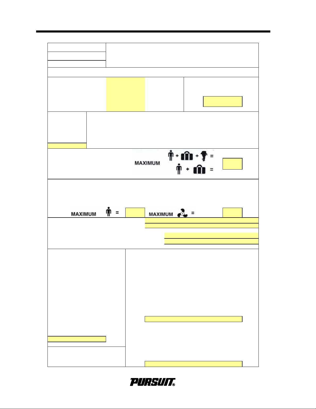
Specifications
C-Inshore Propulsion Type: Tipo di propulsione:
C-
à proximité de la côte
Antriebsart: Tipo de propulsión:
C-Costera Type de propulsion: Tipo propulsão:
C-Küstennane
Gewässer
C-Costeira
C-Perto da Costa
Intended Use:
Verwendungszweck: Hull Identification Number:
Usage prévu: Rumpfunner:
Utilizzo previsto: Nemero d'identification de coque:
Uso previsto: Nemero identificazione scafo:
Utilização: Numero de Identificacion del Casco:
Número de Identificação do Casco:
Maximum Recommended Load:
Charge maximale recommandée:
Carga Máxima recomendada:
Empfohiene Beladung Maximum:
Carico massimo ammesso:
Carga Máxima Recomendada:
Recommended Number of Persons: Maximum Rated Engine Power:
Nombre de personnes recommandé: Puissance nominale maximale du moteur:
Número recomendado de personas: Potencia máxima del motor:
Empfohlene Personenanzahl: Maximale Motorleistung:
Omologazione al trasporto di n. persone: Massima potenza nominale motore:
Número de Pessoas Recomendado: Máxima potência nominal do motor:
500 HP
Engine Installed, Manufacturer, Model and Number(s):
Moteur installé, Fabricant, modèle et numéros(s):
Motor instalado, Fabricante, modelo y numero(s):
Motor instaliert, Hersteller, modell, nummer(en):
1.
Motore istallato, Costruttore, modello e numero(s): 2.
Motor Instalado, Fabricante, Modelo e Número(s):
Mass of Craft (Approximate) With Largest Equipped Engine and permanently attached items,
Masses de Navire (Approximatives) plus full water and fuel, plus maximum recommended load:
Peso de la embarcación (aproximado) Avec le plus grand moteur équipé et systèmes en liaison
Gewicht des Bootes (Nährungswert) permanente, plus pleine charge d'eau et de carburant, plus
Massa dell'imbarcazione (approssimativa) charge maximale recommandée:
Massa da Embarcação (Aproximada) Con el mayor motor equipado y elementos permanentemente
With Largest Equipped Engine and instalados, más combustible y aqua, más la carga máxima recomendada:
permanently attached items: Mit größter Motorausführung und fest installiertem Inventar sowie
Avec le plus grand moteur équipé et vollen Wasser- und Kraftstofftanks und empfohlener Maximalbeladung:
systèmes en liaison permanente: Con il motore di maggiore cilindrata, attrezzature permanenti, più
Con el mayor motor equipado y elementos rifornimento di axqua e carburante e carco massimo ammesso:
permanentemente instalados: Com o maior motor instalado e os equipamentos permanentes, mais a
Mit größter Mororausführung und fest capacidade máxima de água e combustível, mais a carga máxima
installiert em Inventar: recomendada:
Con il motore di maggiore cilindrata e
kg.
attrezzature permanenti: Trailerable Weight (engine, fuel and water, batteries and options):
Cim o maior motor instaldo e os Masse pour remorquage (moteur, carburant et eau, batteries et options):
epuipamentos permanentes: Peso remolcable (motor, combustible y agua, baterías y opciones):
kg.
Auf Anhänger verladbares Gewicht (Motor, Kraftstoff und Wasser, Batterien
und Sonderausstattung):
Peso rimorchiabile su strada (motore, combustible e acgua, batterie ed
accessori):
Peso Rebocável (motor, combustível e água, baterieas e opções):
kg.
Small Craft Owner's Manual
Supplement
Pursuit SS 310
Rev: 6/10/2008
Pursuit C 310
Outboard
Categoria di progetto:
Boat Manufacturer/Model: Constructeur/Modèle du bateau: Modelo/Fabricante de la Embarcación:
Boothersteller/Model: Costruttore/modello della barca: Fabricante/Modelo do Barco:
Design Category:
Categorie de conception:
Categoria de Diseño:
Konstruktionskategorie:
kg.
10 373 kw.
5400
3740
Categoria de Design:
HIN Label
Recreation
1388
Note:Information obtained from 2008 CE
Certificate and/or Specification Sheet
REDUCED 3/28/08
4553
2
C280 / S280 / C310 / ST310
Page 7
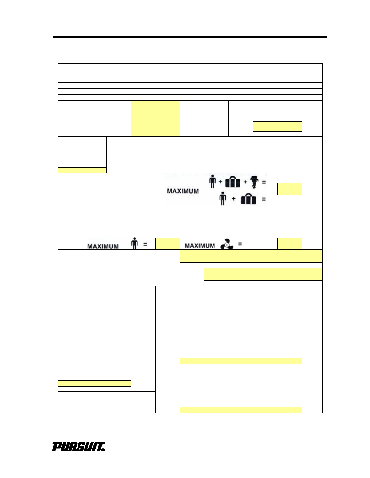
Specifications
C-Inshore Propulsion Type: Tipo di propulsione:
C-
à proximité de la côte
A
ntriebsart: Tipo de propulsión:
C-Costera Type de propulsion: Tipo propulsão:
C-Küstennane
Gewässer
C-Costeira
C-Perto da Costa
Intended Use:
Verwendungszweck: Hull Identification Number:
Usage prévu: Rumpfunner:
Utilizzo previsto: Nemero d'identification de coque:
Uso previsto: Nemero identificazione scafo:
Utilização: Numero de Identificacion del Casco:
Número de Identificação do Casco:
Maximum Recommended Load:
Charge maximale recommandée:
Carga Máxima recomendada:
Empfohiene Beladung Maximum:
Carico massimo ammesso:
Carga Máxima Recomendada:
Recommended Number of Persons: Maximum Rated Engine Power:
Nombre de personnes recommandé: Puissance nominale maximale du moteur:
Número recomendado de personas: Potencia máxima del motor:
Empfohlene Personenanzahl: Maximale Motorleistung:
Omologazione al trasporto di n. persone: Massima potenza nominale motore:
Número de Pessoas Recomendado: Máxima potência nominal do motor:
Engine Installed, Manufacturer, Model and Number(s):
Moteur installé, Fabricant, modèle et numéros(s):
Motor instalado, Fabricante, modelo y numero(s):
Motor instaliert, Hersteller, modell, nummer(en):
1.
Motore istallato, Costruttore, modello e numero(s): 2.
Motor Instalado, Fabricante, Modelo e Número(s):
Mass of Craft (Approximate) With Largest Equipped Engine and permanently attached items,
Masses de Navire (Approximatives) plus full water and fuel, plus maximum recommended load:
Peso de la embarcación (aproximado) Avec le plus grand moteur équipé et systèmes en liaison
Gewicht des Bootes (Nährungswert) permanente, plus pleine charge d'eau et de carburant, plus
Massa dell'imbarcazione (approssimativa) charge maximale recommandée:
Massa da Embarcação (Aproximada) Con el mayor motor equipado y elementos permanentemente
With Largest Equipped Engine and instalados, más combustible y aqua, más la carga máxima recomendada:
permanently attached items: Mit größter Motorausführung und fest installiertem Inventar sowie
Avec le plus grand moteur équipé et vollen Wasser- und Kraftstofftanks und empfohlener Maximalbeladung:
systèmes en liaison permanente: Con il motore di maggiore cilindrata, attrezzature permanenti, più
Con el mayor motor equipado y elementos rifornimento di axqua e carburante e carco massimo ammesso:
permanentemente instalados: Com o maior motor instalado e os equipamentos permanentes, mais a
Mit größter Mororausführung und fest capacidade máxima de água e combustível, mais a carga máxima
installiert em Inventar: recomendada:
Con il motore di maggiore cilindrata e
attrezzature permanenti: Trailerable Weight (engine, fuel and water, batteries and options):
Cim o maior motor instaldo e os Masse pour remorquage (moteur, carburant et eau, batteries et options):
epuipamentos permanentes: Peso remolcable (motor, combustible y agua, baterías y opciones):
Auf Anhänger verladbares Gewicht (Motor, Kraftstoff und Wasser, Batterien
und Sonderausstattung):
Peso rimorchiabile su strada (motore, combustible e acgua, batterie ed
accessori):
Peso Rebocável (motor, combustível e água, baterieas e opções):
Constructeur/Modèle du bateau: C310 or SS310 Fabricante/Modelo do Barco: C310 or SS310
10
373 kw.
500 hp.
1388 kg.
3060 lbs.
Categoria de Diseño:
Konstruktionskategorie:
5400 kg. 11905 lbs.
4553 kg./ 10038 lbs.
Note:Information obtained from 200 CE
Certificate and/or Specification Sheet
1/22/09 rev. G
Recreation
Categoria di progetto:
Categoria de Design:
3740 kg./ 8245 lbs.
Specifications
6/10/2008
Boat Manufacturer/Model: C310 or SS310
Boothersteller/Model: C310 or SS310
Costruttore/modello della barca: C310 or SS310
Modelo/Fabricante de la Embarcación: C310 or SS310
Design Category:
Categorie de conception:
HIN Label
Outboard
0B
C280 / S280 / C310 / ST310
3
Page 8
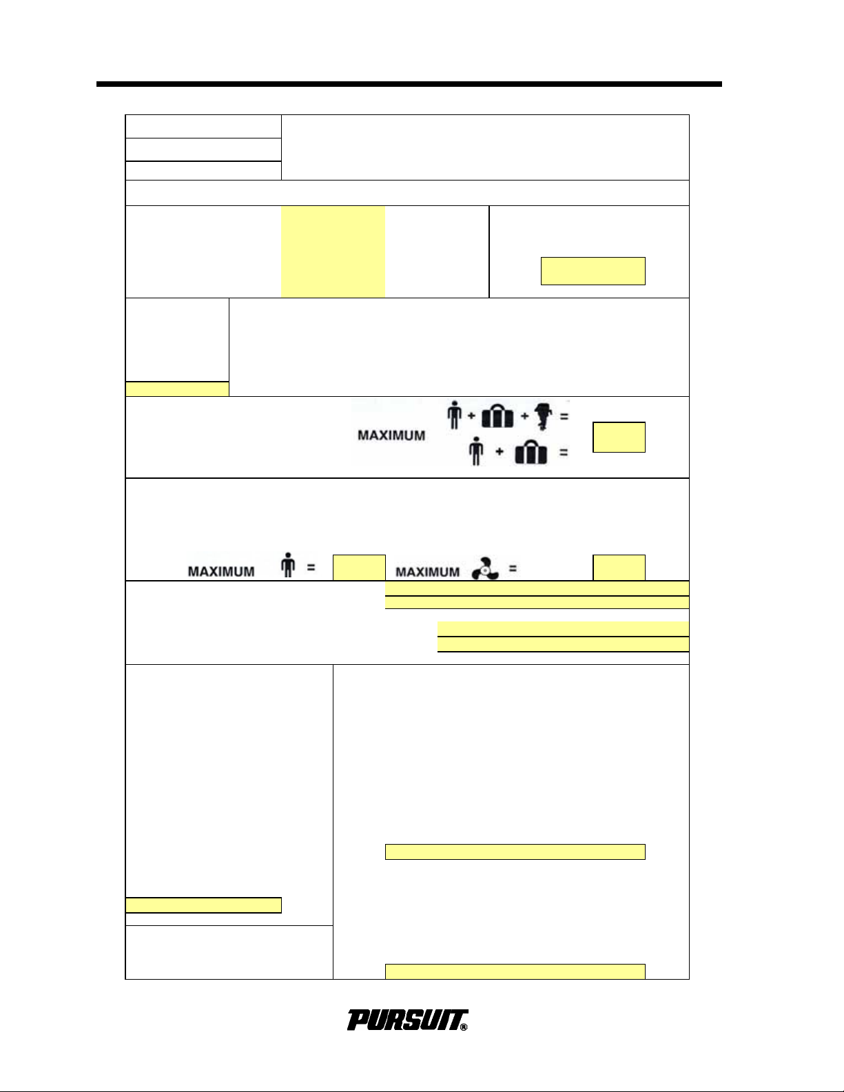
Specifications
C-Inshore Propulsion Type: Tipo di propulsione:
C-
à proximité de la côte
Antriebsart: Tipo de propulsión:
C-Costera Type de propulsion: Tipo propulsão:
C-Küstennane
Gewässer
C-Costeira
C-Perto da Costa
Intended Use:
Verwendungszweck: Hull Identification Number:
Usage prévu: Rumpfunner:
Utilizzo previsto: Nemero d'identification de coque:
Uso previsto: Nemero identificazione scafo:
Utilização: Numero de Identificacion del Casco:
Número de Identificação do Casco:
Maximum Recommended Load:
Charge maximale recommandée:
Carga Máxima recomendada:
Empfohiene Beladung Maximum:
Carico massimo ammesso:
Carga Máxima Recomendada:
Recommended Number of Persons: Maximum Rated Engine Power:
Nombre de personnes recommandé: Puissance nominale maximale du moteur:
Número recomendado de personas: Potencia máxima del motor:
Empfohlene Personenanzahl: Maximale Motorleistung:
Omologazione al trasporto di n. persone: Massima potenza nominale motore:
Número de Pessoas Recomendado: Máxima potência nominal do motor:
500 HP
Engine Installed, Manufacturer, Model and Number(s):
Moteur installé, Fabricant, modèle et numéros(s):
Motor instalado, Fabricante, modelo y numero(s):
Motor instaliert, Hersteller, modell, nummer(en):
1.
Motore istallato, Costruttore, modello e numero(s): 2.
Motor Instalado, Fabricante, Modelo e Número(s):
Mass of Craft (Approximate) With Largest Equipped Engine and permanently attached items,
Masses de Navire (Approximatives) plus full water and fuel, plus maximum recommended load:
Peso de la embarcación (aproximado) Avec le plus grand moteur équipé et systèmes en liaison
Gewicht des Bootes (Nährungswert) permanente, plus pleine charge d'eau et de carburant, plus
Massa dell'imbarcazione (approssimativa) charge maximale recommandée:
Massa da Embarcação (Aproximada) Con el mayor motor equipado y elementos permanentemente
With Largest Equipped Engine and instalados, más combustible y aqua, más la carga máxima recomendada:
permanently attached items: Mit größter Motorausführung und fest installiertem Inventar sowie
Avec le plus grand moteur équipé et vollen Wasser- und Kraftstofftanks und empfohlener Maximalbeladung:
systèmes en liaison permanente: Con il motore di maggiore cilindrata, attrezzature permanenti, più
Con el mayor motor equipado y elementos rifornimento di axqua e carburante e carco massimo ammesso:
permanentemente instalados: Com o maior motor instalado e os equipamentos permanentes, mais a
Mit größter Mororausführung und fest capacidade máxima de água e combustível, mais a carga máxima
installiert em Inventar: recomendada:
Con il motore di maggiore cilindrata e
kg.
attrezzature permanenti: Trailerable Weight (engine, fuel and water, batteries and options):
Cim o maior motor instaldo e os Masse pour remorquage (moteur, carburant et eau, batteries et options):
epuipamentos permanentes: Peso remolcable (motor, combustible y agua, baterías y opciones):
kg.
Auf Anhänger verladbares Gewicht (Motor, Kraftstoff und Wasser, Batterien
und Sonderausstattung):
Peso rimorchiabile su strada (motore, combustible e acgua, batterie ed
accessori):
Peso Rebocável (motor, combustível e água, baterieas e opções):
kg.
Small Craft Owner's Manual
Supplement
Pursuit SS 310
Rev: 6/10/2008
Pursuit C 310
Outboard
Categoria di progetto:
Boat Manufacturer/Model: Constructeur/Modèle du bateau: Modelo/Fabricante de la Embarcación:
Boothersteller/Model: Costruttore/modello della barca: Fabricante/Modelo do Barco:
Design Category:
Categorie de conception:
Categoria de Diseño:
Konstruktionskategorie:
kg.
10 373 kw.
5400
3740
Categoria de Design:
HIN Label
Recreation
1388
Note:Information obtained from 2008 CE
Certificate and/or Specification Sheet
REDUCED 3/28/08
4553
4
C280 / S280 / C310 / ST310
Page 9
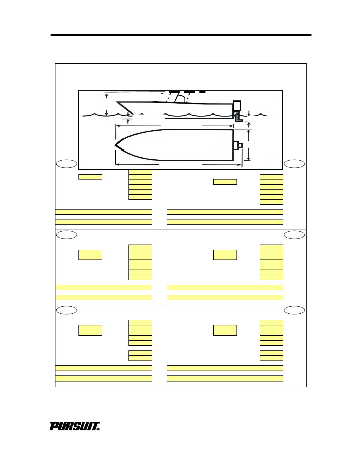
Specifications
Fuel Tank Capacity (0.73kg/Liter): 832L/ 220G
Kraftstofftankkapazität
Fuel Type:
9
Gasoline N/A Diesel 832 Liter
Oil Tank Capacity: N/A Liters Kraftstoffart:
9
Benzin N/A Diesel
Oil Type: 10-40
Öltankkapazität:
N/A Liter
Water Tank Capacity (1kg/Liter): 76L/ 20 Gal
Ölsorte:
10-40
Holding Tank Capacity: 76L/ 20 Gal Wassertankkapazität (1kg/Liter): 76 Liter
Number and Type of Fire Extinguishers: Speichertankkapazität: 76 Liter
Feuerlöscheranzahl und -typ:
Number and Type of CO Detectors: Rauchdetektoranzahl und -typ
N/A = Not Applicable n.z. = nicht zuttrefend
Contenance réservoir carburant
Capacità serbatoio carburante
(0,73kg/litre): 832 litres (0,73kg/l): 832 litri
Type de
carburant:
9
gasoil
N/A
diesel Tipo carburante:
9
Benzina
N/A
Diesel
Contenance réservoir d'huile: N/A litres
Capacità serbatoio olio:
N/A litri
Type d'huile: 10-40 Tipo oilio: 10-40
Contenance réservoir de'eau (kg/litre) 76 litres
Capacità serbatoio acqua (1kg/l):
76 litri
Contenance réservoir de rétention: 76
Capacità cassa di zavorra:
76 litri
Nombre et type d'extincteurs: Numbero e tipo di estintori:
Nombre et type de détecteurs de fumée: Nummero e tipo di rivelatori di esalazioni:
N/A = non applicable N/A = non pertinente
Capacidad del Depósito de Combustible Capacidade do Depósito de Combust
vel:
(73Kg/Litro): 832 Litros (0,73kg/Litro): 832 Litros
Tipo de
Combustible
9
Gasolina
N/A
Diesel Tipo de Combustível:
9
Gasolina
N/A
Gasóleo
Capacidad del Depósito de Aceite: N/A Litros
Capacidade do Depósito de Óleo:
N/A Litros
Tipo de Aceite: 10-40
Tipo de
Ó
leo:
10-40
Capacidad del Depósito de Agua
Capacidade do Depósito de Água:
(1Kg/Litro): 76 Litros (1kg/Litro): 76 Litros
Capacidad del Tanque de Retención:
76 Litros
Capacidade do Depósito Provisório:
76 Litros
Número y Tipo de Extintores de Incendios:
Número e Tipo de Extintores de Incêndio:
Número y Tipo de Detedtores de Humos:
Número e Tipo de Detectores de Fumo:
N/A = no aplicable N/A = Não Aplicàvel
Note:Information obtained from 2009 CE Certificate and/or Specification Sheet 1/22/09 rev. G
(3) A,B,C
Specifications
1/22/2009
Model: C280 or S280
EN
(3) A,B,C(3) A,B,C
(0,73 kg/Liter):
00
(3) A,B,C
0 0
(3) A,B,C
00
(3) A,B,C
FR IT
ES PT
DE
2.9 m/ 9.5ft
9.1 m/ 28 ft
.81 m/ 3.1 ft
2.51 m
8.23 ft
10.16 m/ 30 ft
0B
í
C280 / S280 / C310 / ST310
5
Page 10
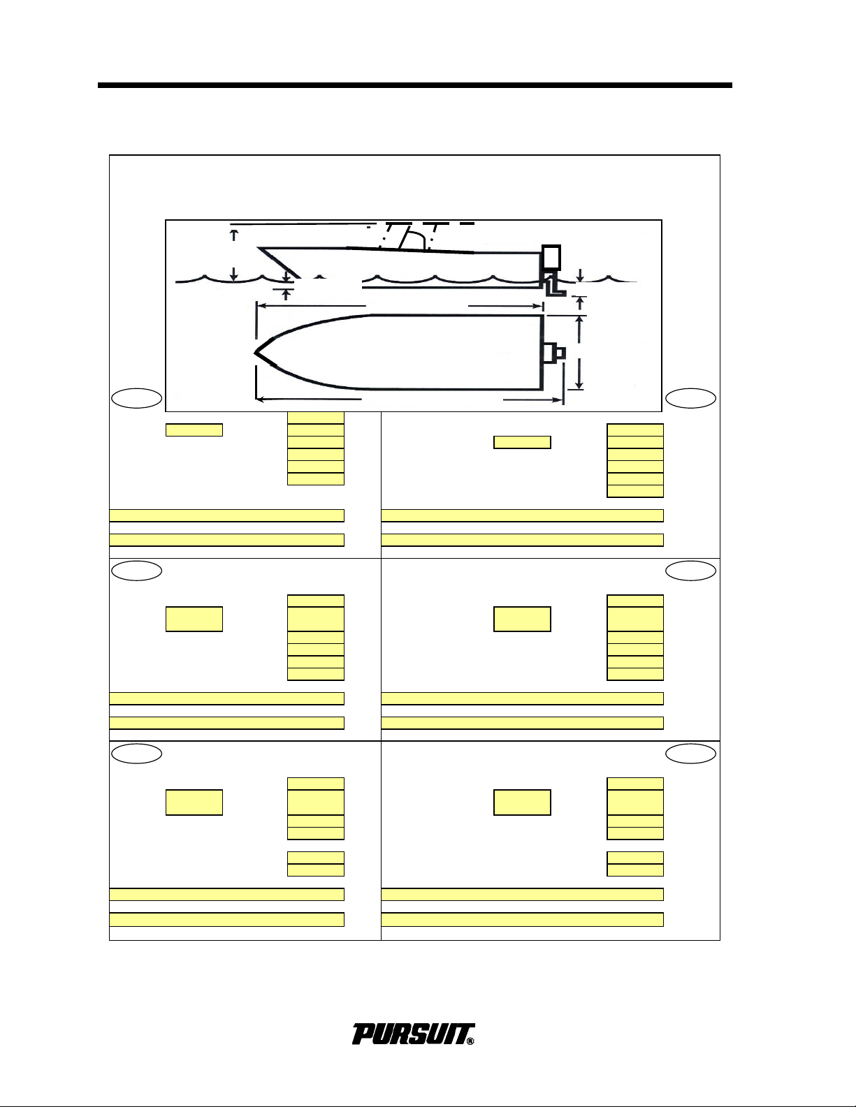
Specifications
Fuel Tank Capacity (0.73kg/Liter): 984L/ 260G
Kraftstofftankkapazität
Fuel Type:
9
Gasoline N/A Diesel 984 Liter
Oil Tank Capacity: N/A Liters Kraftstoffart:
9
Benzin N/A Diesel
Oil Type: 10-40
Öltankkapazität:
N/A Liter
Water Tank Capacity (1kg/Liter): 76L/ 20 Gal Liters
Ölsorte:
10-40
Holding Tank Capacity: 76L/ 20 Gal Liters Wassertankkapazität (1kg/Liter): 76 Liter
Number and Type of Fire Extinguishers: Speichertankkapazität: 76 Liter
Feuerlöscheranzahl und -typ:
Number and Type of CO Detectors: Rauchdetektoranzahl und -typ
N/A = Not Applicable n.z. = nicht zuttrefend
Contenance réservoir carburant
Capacità serbatoio carburante
(0,73kg/litre): 984 litres (0,73kg/l): 984 litri
Type de
carburant:
9
gasoil
N/A
diesel Tipo carburante:
9
Benzina
N/A
Diesel
Contenance réservoir d'huile: N/A litres
Capacità serbatoio olio:
N/A litri
Type d'huile: 10-40 Tipo oilio: 10-40
Contenance réservoir de'eau (kg/litre) 76 litres
Capacità serbatoio acqua (1kg/l):
76 litri
Contenance réservoir de rétention: 76
Capacità cassa di zavorra:
76 litri
Nombre et type d'extincteurs: Numbero e tipo di estintori:
Nombre et type de détecteurs de fumée: Nummero e tipo di rivelatori di esalazioni:
N/A = non applicable N/A = non pertinente
Capacidad del Depósito de Combustible Capacidade do Depósito de Combust
vel:
(73Kg/Litro): 984 Litros (0,73kg/Litro): 984 Litros
Tipo de
Combustible
9
Gasolina
N/A
Diesel Tipo de Combustível:
9
Gasolina
N/A
Gasóleo
Capacidad del Depósito de Aceite: N/A Litros
Capacidade do Depósito de Óleo:
N/A Litros
Tipo de Aceite: 10-40
Tipo de
Ó
leo:
10-40
Capacidad del Depósito de Agua
Capacidade do Depósito de Água:
(1Kg/Litro): 76 Litros (1kg/Litro): 76 Litros
Capacidad del Tanque de Retención:
76 Litros
Capacidade do Depósito Provisório:
76 Litros
Número y Tipo de Extintores de Incendios:
Número e Tipo de Extintores de Incêndio:
Número y Tipo de Detedtores de Humos:
Número e Tipo de Detectores de Fumo:
N/A = no aplicable N/A = Não Aplicàvel
Note:Information obtained from 2009 CE Certificate and/or Specification Sheet 1/22/09 rev. G
0
(3) A,B,C
EN
(3) A,B,C
(3) A,B,C
0
(3) A,B,C
(0,73 kg/Liter):
(3) A,B,C
00
00
(3) A,B,C
Specifications
6/10/2008
Model: C310 or S310
FR IT
ES PT
DE
.56 m/1.8 ft
2.90 m/ 9.5 ft
9.50 m/ 31 ft
.81 m 2.7 ft
2.51m
8.23 ft
10.16 m/ 33.3 ft
0B
í
6
C280 / S280 / C310 / ST310
Page 11
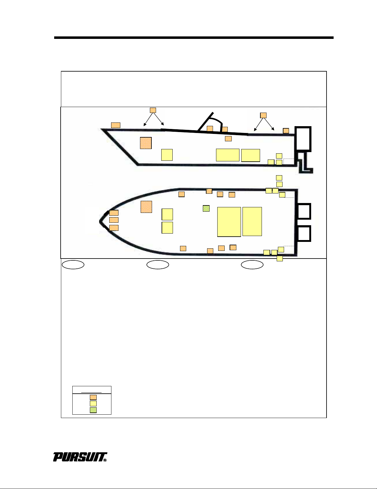
Specifications
Locate and Identify: Localizar e identificar: Localizzazione e identificazione de
i
A
) Fuel Tank
A
) Depósito de Combustible componenti:
B) Fuel Tank Filling Poin
t
B) Punto de Carga del Depósito de
A
) Serbatoio carburante
C) O
il Tank (N/A
)
Combustible B) Bocchettone di riempimento
D
)O
il Tank Filling Point (N/A
)
C)
Depósito de Aceite (N/A
)
serbatoio carburante
E
)O
il Tank Emptying Point (N/A
)
D) Punto de Carga del Depósito de
C) S
erbatoio olio (N/A
)
F) Water Tank
Aceite
(N/A)
D) Bocchettone di riempimento
G) Water Tank Filling Point
E
)
Punto de Descarga del Depósito (N/A) serbatoio olio (N/A
)
H) Holding Tank de Aceite
E
)S
carico serbatoio olio (N/A
)
I) Holding Tank Emptying Point F) Depósito de Agua F) Serbatoio acqua
J) Seacocks G) Punto de Carga del Depósito de G) Bocchettone di riempimento
K) Through-Hull Fittings Agua serbatoio acqua
L) Fire Extinguishe
r
H) Tanque de Tetención H) Cassa zavorra
M
)C
arbon Monoxide Detector (N/A
)
I) Punto de Descarga del
I) S
caric cassa zavorra
N
)
Escape Hatch (N/A
)
Tanque de Tetención J) Valvole di presa acqua dal mare
O)
Fire Escapes (N/A
)
J) Válvula de Toma de Agua de Ma
r
K) Raccorderia passante nello scafo
P) Life Raft Stowage K) Accesorios Pasantes del Casco L) Estintore
Q) Safety Equipmen
t
L) Extintor de Incendios M) Rivelatore monossido di carbonio
R) Anchor Strong Points M) Detector de Monóxido de
carbonio
(N/A)
S) Mooring Strong Points
C
arbono(N/A
)
N) Boccaporto di sfuggita(N/A
)
T) Towing Strong Points (N/A
)
N) Escotilla de Seguridad(N/A
)
O)
Uscite di sicurezza (N/A
)
O)
Escalera de Incendios (N/A
)
P) Stivaggio zattera di salvataggi
o
P) Almacenamiento de balsas Q) Dotazioni di sicurezz
a
salvavidas R) Punti di attaco per l'ancoraggio
Q) Equipos de seguridad S) Punti di attacco per l'ormeggio
R) Puntos fuertes de anclaje
T
)
Punti di attacco per il traino (N/A
)
S) Puntos fuertes de amarre
T
)
Puntos fuertes de remolque (N/A
)
Specifications
1/22/2009
Model: C280 or S280 or C310 or
S310
A
A
H
F
Q
A
F
Q
A
EN ES ITEN ES IT
LEGEND
Deck Hull Head -
0B
C280 / S280 / C310 / ST310
7
Page 12
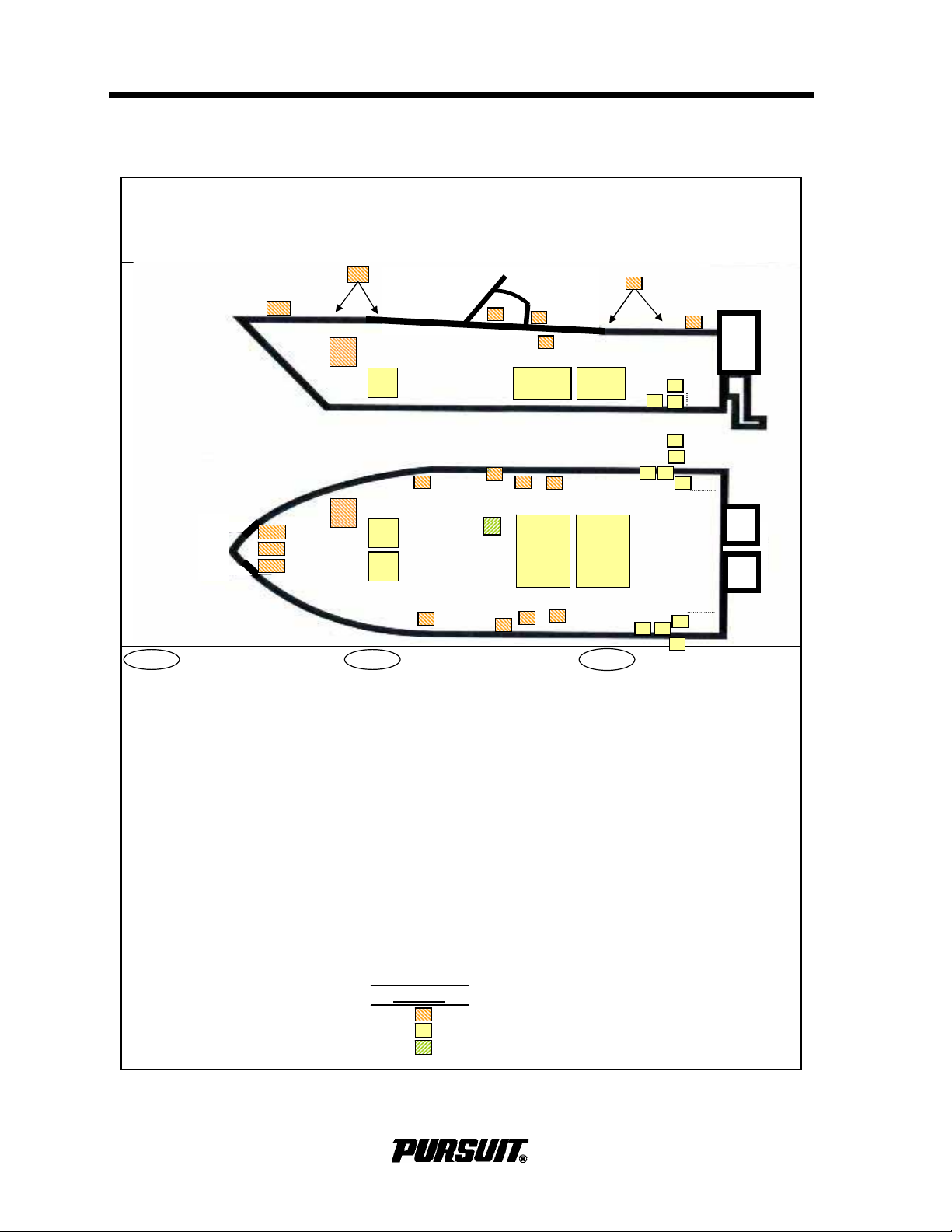
Specifications
Repèrez et identifiez: Position and Beschreibung: Localizar e Identificar:
A
) Réservoir de carburant
A
) Kraftstofftank
A
) Depósito de Conbustível
B) Point de remplissage réservoir B) Kraftstofftankfüllpunkt B) Ponto de Enchimento do Depósito de
de carburant
C)
Ö
ltank (n.z.)
Combustível
C) Réservoir d'huile (N/A)
D)
Ö
ltankfüllpunkt (n.z.) C) Depósito de Óleo (N/A)
D) Point de remplissage réservoir
E)
Ö
ltankablasspunkt (n.z.)
D) Ponto de Enchimento do Depósito de
d'huile (N/A)
F) Wassertank
Ó
leo (N/A)
E) Point de vindage réservoir G) Wassertankablasspunkt E) Ponto de Esvaziamento do Depósito
d'huile (N/A)
H) Speichertank
de
Ó
leo (N/A)
F) Réservoir d'eau I) Speichertankablaßpunkt F) Depósito de
Á
gua
G) Point de remplissage réservoir J) Flutventile G) Ponto de Enchimento do Depósito de
d'eau K) Rumpfdurchgangsanbauten
Á
gua
H) Réservoir de rétention L) Feuerlöscher H) Depósito Provisório
I) Point de vidange résevoir de
M) Kohlenmonoxiddetektor (n.z.)
I) Ponto de Esvaziamento do Depósito
rétention
N) Notausstieg (n.z.)
Provisório
J) Prises d'eau à la mer
O) Reuerrettungswege (n.z.)
J) Torneiras de tomada de àgua do mar
K) Raccords traversant la coque P) Rettungsfloßunterbringung K) Acessórios de Todo o Casco
L) Extincteur Q) Sicherheitsausrüstung L) Extintor de Incêndios
M) Détecteur de monoxyde de R) Ankerpunkte M) Detector de Monóxide de
carbone (N/A)
S) Vertäuungspunkte
Carbono (N/A)
N) Ecoutille d'évacuation (N/A) T) Abschlepppunkte (n.z.) N) Escotilha de Fuga (N/A)
O) Echelles de sauvetage N/A) O) Saídas de Incêndio (N/A)
P) Arrimage du radeau de P) Acondicionamento do Barco
sauvetage Salva-vidas
Q) Equipement de sécurité Q) Equipamento de Segurança
R) Points d'ancrage R) Pontos Fortes da Ancoragem
S) Points d'amarrage S) Pontos Fortes da Amaragem
T) Points de remorquage (N/A) T) Pontos Fortes da Rebocagem (N/A)
Specifications
1/22/2009
Model: C280 or S280 or C310 or
S310
FR DE
PT
AA
H
F
Q
A
F
Q
A
P
LEGEND
Deck Hull Head -
L
0B
8
C280 / S280 / C310 / ST310
Page 13
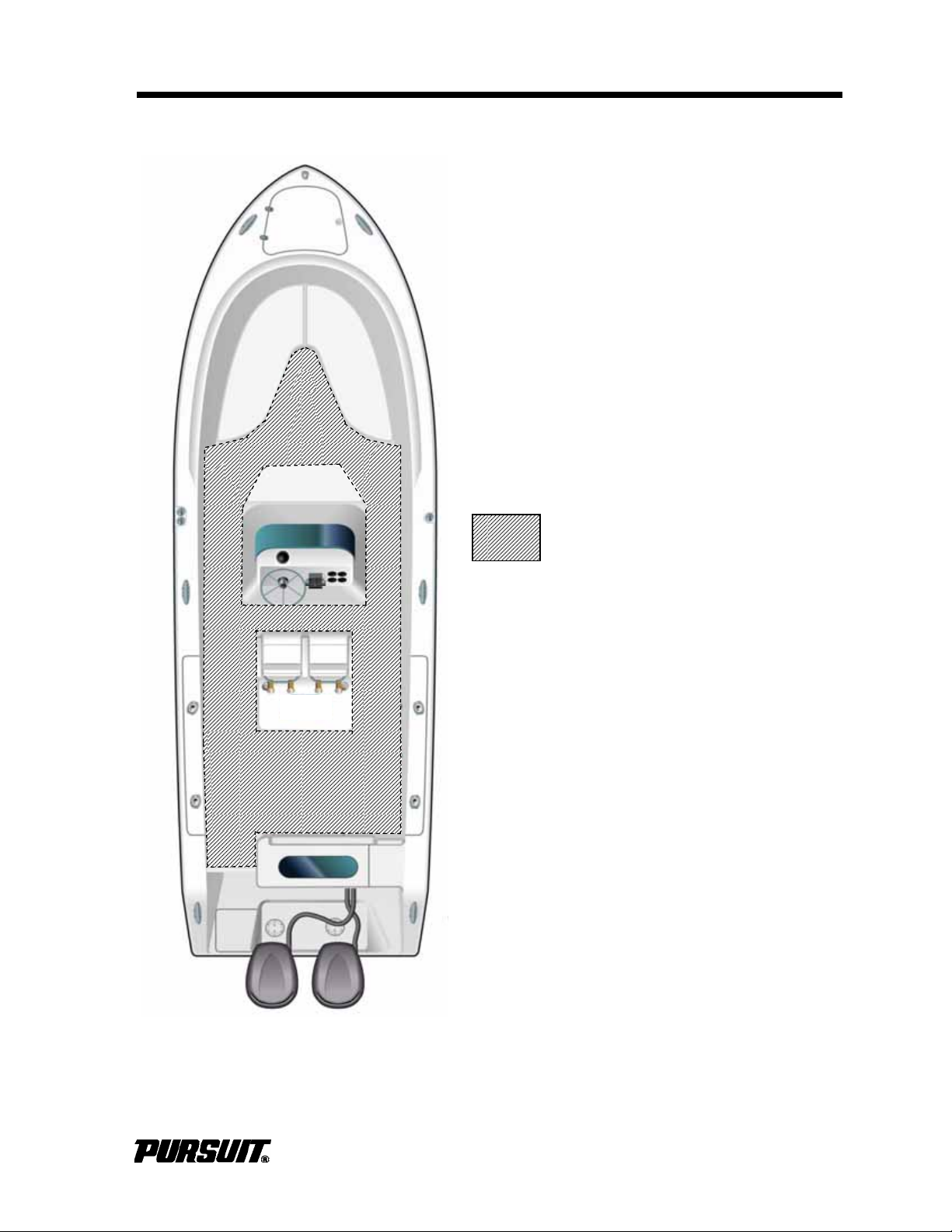
Specifications
Working Deck
Sunlounger option not intended
to be used as a working deck.
WARNING:
Areas for occupation during normal
operation of the boat
Working Deck Area
1/22/2009
Model: C280 or S280 or C310 or S310
C280 / S280 / C310 / ST310
9
Page 14
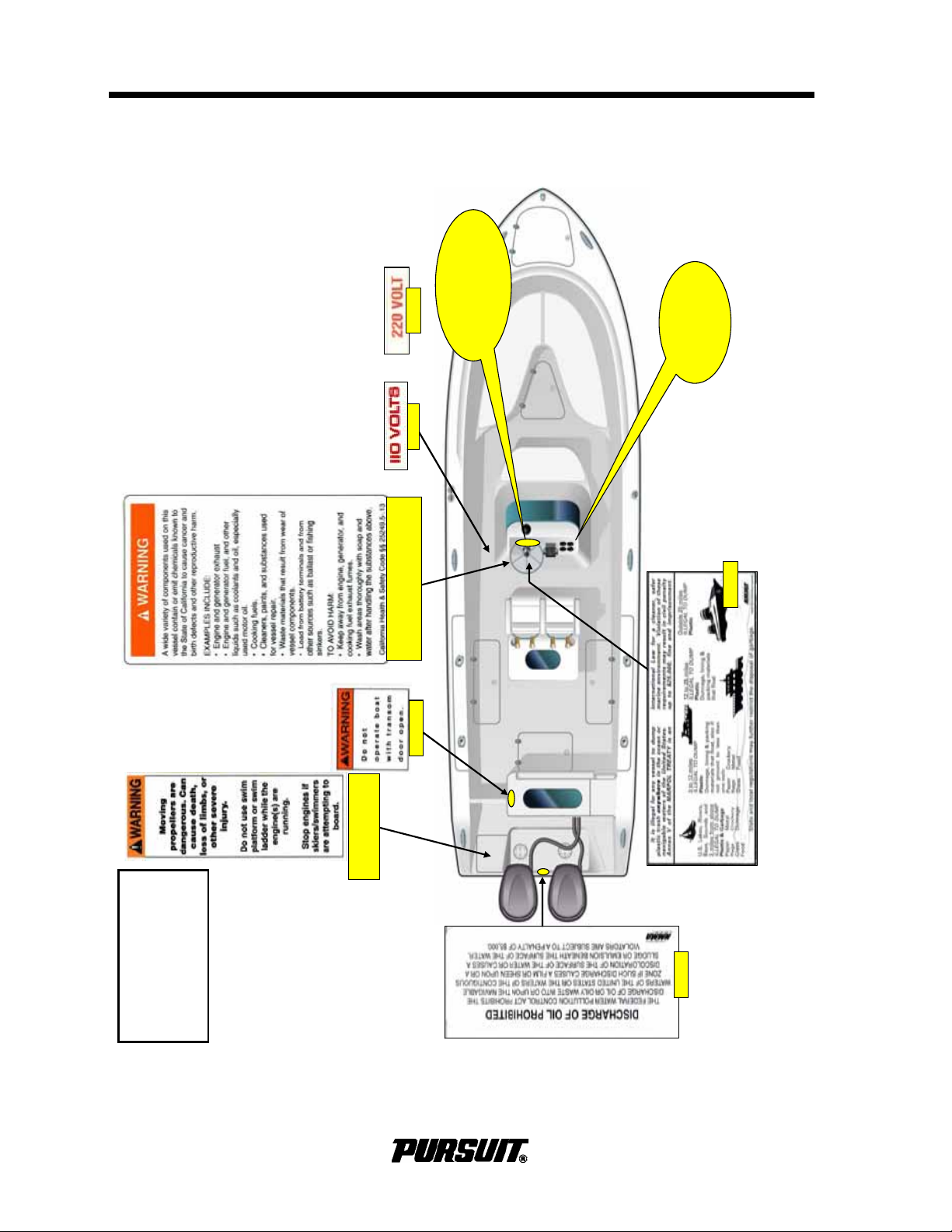
Specifications
Warning Label
Locations
C280 / S280
C310 / S310
545055
545011
Next to the cabin floor drain
545355
Attached to the steering wheel
Detail A
Inside Stbd
Helm Wing
Detail B
Forward of the
Steering wheel
o
r
545175 Attached
to the ladder
0B
10
C280 / S280 / C310 / ST310
Page 15
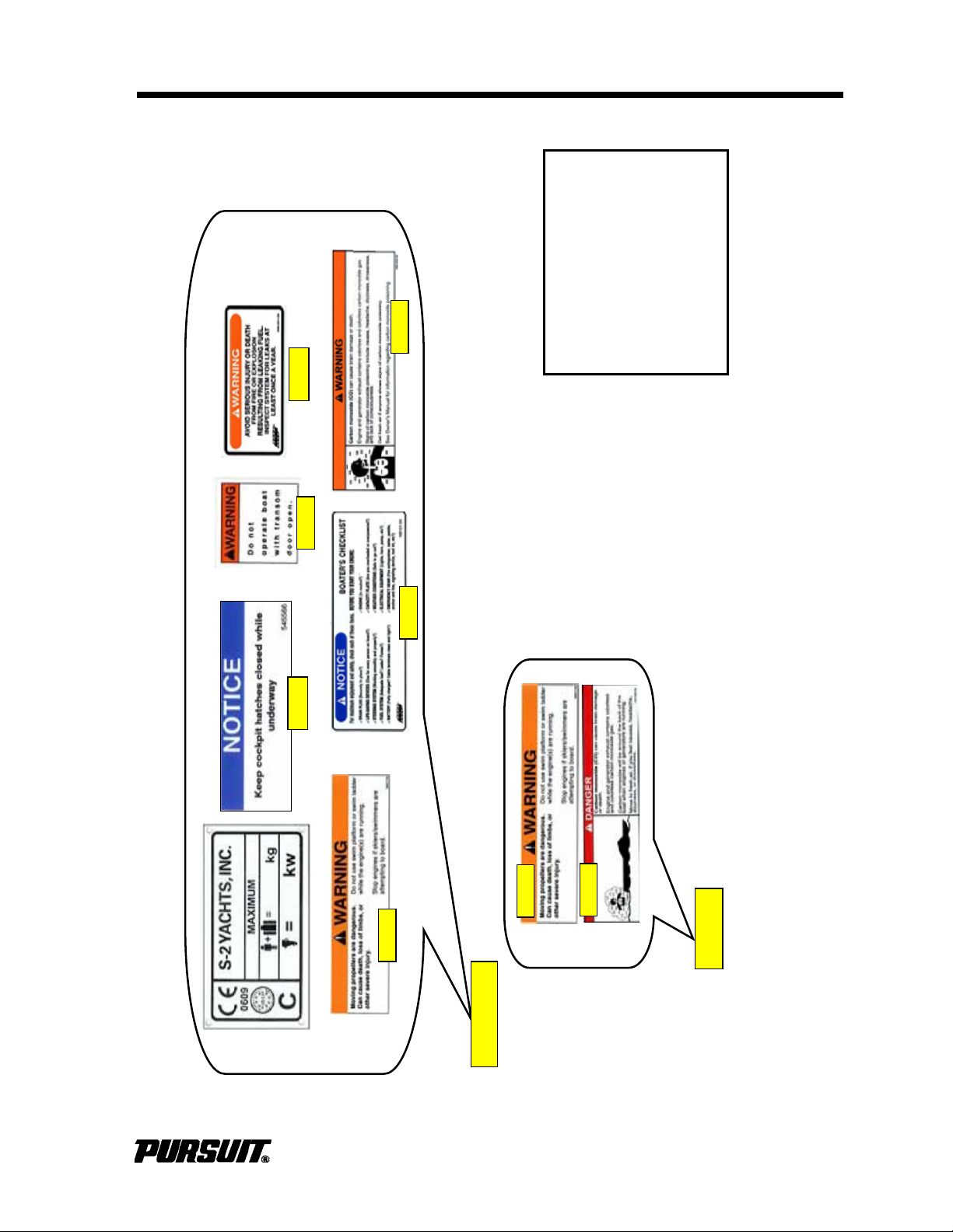
Specifications
1/22/200
9
545006
545012
545369
545118
545365
Detail B
545118
Detail A
545055
Warning Label
Locations
C280 / S280
C310 / S310
545566
C280 / S280 / C310 / ST310
11
Page 16
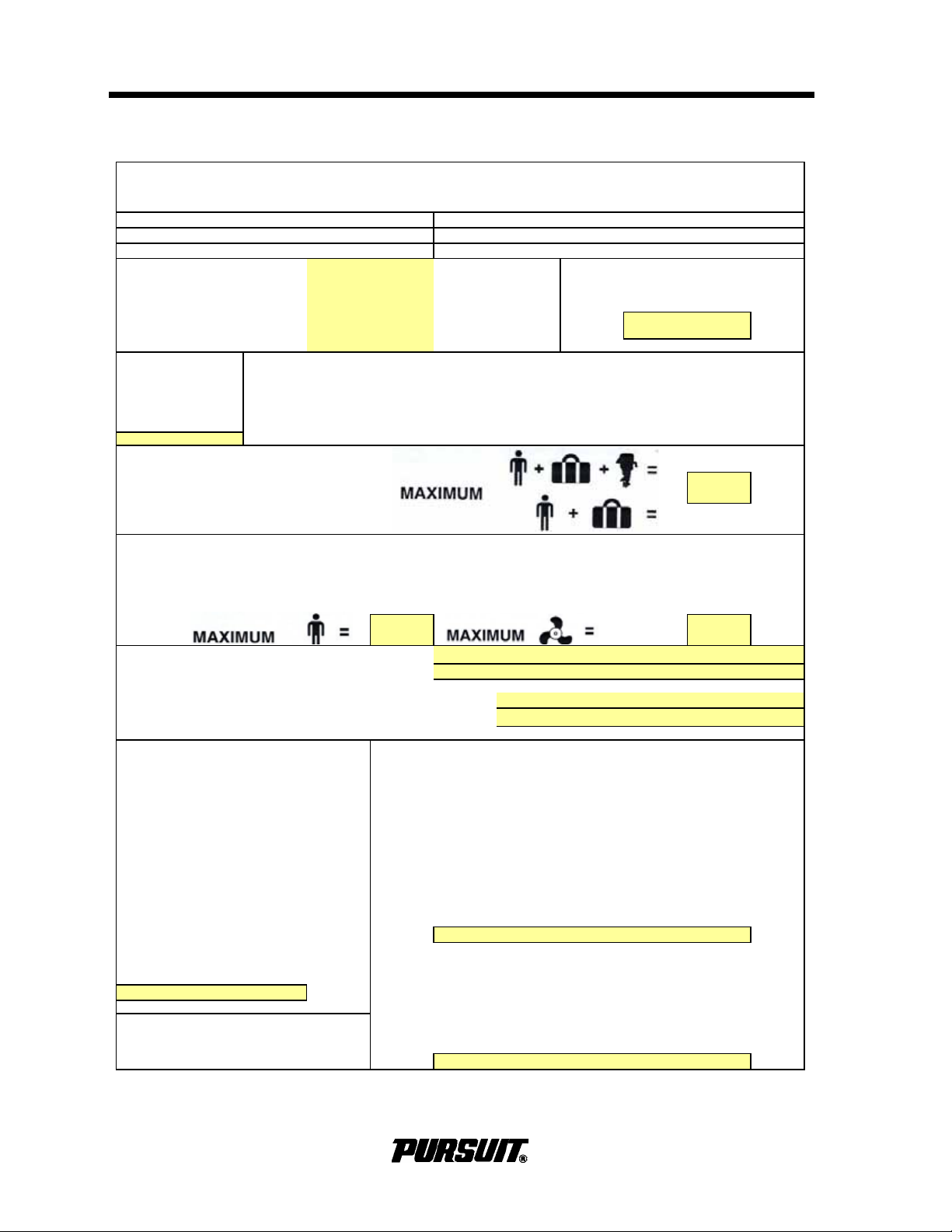
C-Inshore Propulsion Type: Tipo di propulsione:
C-
à proximité de la côte
A
ntriebsart: Tipo de propulsión:
C-Costera
T
y
pe de propulsion
:
Tipo propulsão:
C-Küstennan
e
Gewässe
r
C-Costeira
C-Perto da Cost
a
Intended Use:
Verwendun
g
szweck:Hull Identification Number:
Usa
g
e prévu: Rumpfunner:
Utilizzo previsto:
Nemero d'identification de coque
:
Uso previsto: Nemero identificazione scafo:
Utilização:
Numero de Identificacion del Casco
:
Número de Identificação do Casco
:
Maximum Recommended Load
:
Charge maximale recommandée
:
Carga Máxima recomendada:
Empfohiene Beladung Maximum:
Carico massimo ammesso:
Carga Máxima Recomendada:
Recommended Number of Persons:
Maximum Rated En
g
ine Power
:
Nombre de personnes recommandé
:
Puissance nominale maximale du moteur
:
Número recomendado de personas
:
Potencia máxima del motor
Empfohlene Personenanzahl
:
Maximale Motorleistun
g:
Omologazione al trasporto di n. persone
:
Massima potenza nominale motore
:
Número de Pessoas Recomendado
:
Máxima potência nominal do motor
:
Engine Installed, Manufacturer, Model and Number(s):
Moteur installé, Fabricant, modèle et numéros(s):
Motor instalado, Fabricante, modelo
y
numero(s
):
Motor instaliert, Hersteller, modell, nummer(en): 1.
Motore istallato, Costruttore, modello e numero(s): 2.
Motor Instalado, Fabricante, Modelo e Número(s
):
Mass of Craft (Approximate
)
With Largest Equipped Engine and permanently attached items
Masses de Navire
(
Approximatives
)
plus full water and fuel, plus maximum recommended load
Peso de la embarcación
(
aproximado
)
Avec le plus grand moteur équipé et systèmes en liaiso
n
Gewicht des Bootes (Nährungswert
)
permanente, plus pleine charge d'eau et de carburant, plu
s
Massa dell'imbarcazione (approssimativa
)
charge maximale recommandée
:
Massa da Embarcação (Aproximada
)
Con el mayor motor equipado y elementos permanentement
e
With Largest Equipped Engine and instalados, más combustible y aqua, más la carga máxima recomendada
permanentl
y
attached items
:
Mit größter Motorausführung und fest installiertem Inventar sowi
e
Avec le plus grand moteur équipé e
t
vollen Wasser- und Kraftstofftanks und empfohlener Maximalbeladun
g:
systèmes en liaison permanente
:
Con il motore di maggiore cilindrata, attrezzature permanenti, pi
ù
Con el mayor motor equipado y elemento
s
rifornimento di axqua e carburante e carco massimo ammesso
:
permanentemente instalados
:
Com o maior motor instalado e os equipamentos permanentes, mais
a
Mit größter Mororausführung und fes
t
capacidade máxima de água e combustível, mais a carga máxim
a
installiert em Inventar: recomendada:
Con il motore di maggiore cilindrata e
attrezzature permanenti
:
Trailerable Weight(engine, fuel and water, batteries and options
)
Cim o maior motor instaldo e o
s
Masse pour remorquage(moteur, carburant et eau, batteries et options
)
epuipamentos permanentes: Peso remolcable (motor, combustible y agua, baterías y opciones):
Auf Anhänger verladbares Gewicht (Motor, Kraftstoff und Wasser, Batterien
und Sonderausstattun
g):
Peso rimorchiabile su strada (motore, combustible e acgua, batterie ed
accessori
)
:
Peso Rebocável
(
motor, combustível e água, baterieas e opções
)
Specifications
1/18/11
Boat Manufacturer/Model: ST310
Boothersteller/Model: ST310
Costruttore/modello della barca: ST310
Modelo/Fabricante de la Embarcación: ST310
448 kw.
600 hp.
1617 kg.
3565 lbs.
Recreation
Categoria di progetto:
5133 kg./ 11316 lbs.
4032 kg./ 8890 lbs.
Categoria de Diseño:
Konstruktionskate
g
orie:
6110 kg. 13470 lbs.
Note:Information obtained from 200 CE
Certificate and/or Specification Sheet
11/10/09 rev. H
Outboard
Constructeur/Modèle du bateau: ST310 Fabricante/Modelo do Barco: ST310
12
Categoria de Design:
Desi
g
n Category:
Cate
g
orie de conception
:
HIN Label
0B
12
:
C280 / S280 / C310 / ST310
Specifications
Page 17
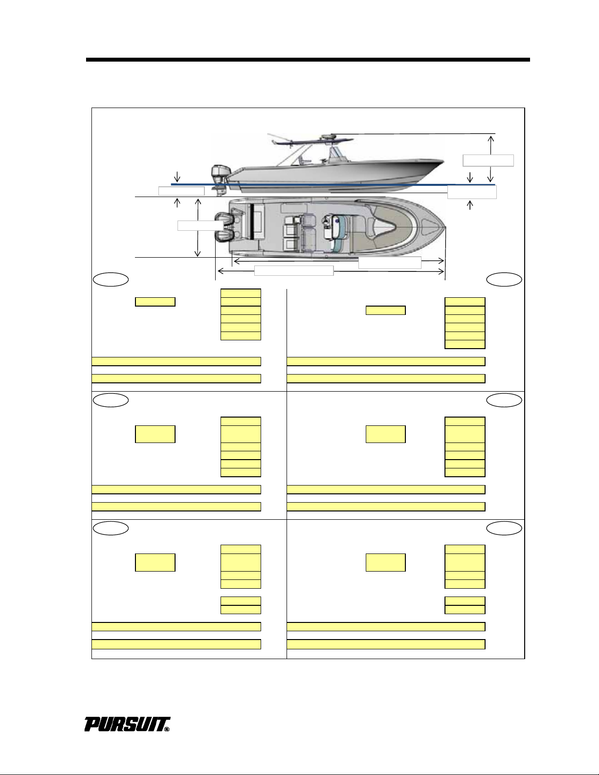
Specifications
2/1/2011
Fuel Tank Capacity (0.73kg/Liter): 984L/ 260G
Kraftstofftankkapazität
Fuel Type: 9 Gasoline N/A Diesel 984 Liter
Oil Tank Capacity: N/A Liters Kraftstoffart: 9 Benzin N/A Diesel
Oil Type: 10-40
Öltankkapazi
:ät
N/A Liter
Water Tank Capacity (1kg/Liter): 76L/ 20 Gal Liters
Ölsorte:
10-40
Holding Tank Capacity: 76L/ 20 Gal Liters Wassertankkapazität (1kg/Liter): 76 Liter
Number and Type of Fire Extinguishers: Speichertankkapazität: 76 Liter
Feuerlöscheranzahl und -typ:
Number and Type of CO Detectors: Rauchdetektoranzahl und -typ
N/A = Not Applicable n.z. = nicht zuttrefend
Contenance réservoir carburant
Capacità serbatoio carburante
(0,73kg/litre): 984 litres (0,73kg/l): 984 litri
Type de
carburant:
9
gasoil
N/A
diesel Tipo carburante:
9
Benzina
N/A
Diesel
Contenance réservoir d'huile: N/A litres
Capacità serbatoio olio:
N/A litri
Type d'huile: 10-40 Tipo oilio: 10-40
Contenance réservoir de'eau (kg/litre) 76 litres
Capacità serbatoio acqua (1kg/l):
76 litri
Contenance réservoir de rétention: 76
Capacità cassa di zavorra:
76 litri
Nombre et type d'extincteurs: Numbero e tipo di estintori:
Nombre et type de détecteurs de fumée: Nummero e tipo di rivelatori di esalazioni:
N/A = non applicable N/A = non pertinente
Capacidad del Depósito de Combustible Capacidade do Dep ósito de Combustível:
(73Kg/Litro): 984 Litros (0,73kg/Litro): 984 Litros
Tipo de
Combustible
9
Gasolina
N/A
Diesel Tipo de Combustível:
9
Gasolina
N/A
Gasóleo
Capacidad del Depósito de Aceite: N/A Litros Capacidade do Depósito de Óleo: N/A Litros
Tipo de Aceite: 10-40
Tipo de
Ó
leo:
10-40
Capacidad del Depósito de Agua Capacidade do Depósito de Água:
(1Kg/Litro): 76 Litros (1kg/Litro): 76 Litros
Capacidad del Tanque de Retención:
76 Litros Capacidade do Depósito Provisório: 76 Litros
Número y Tipo de Extintores de Incendios:
Número e Tipo de Extintores de Incêndio:
Número y Tipo de Detedtores de Humos:
Número e Tipo de Detectores de Fumo:
N/A = no aplicable N/A = Não Aplicàvel
Note:Information obtained from 2009 CE Certificate and/or Specification Sheet 11/10/09 rev. H
(0,73 kg/Liter):
00
(3) A,B,C
0 0
(3) A,B,C(3) A,B,C
ST310
Specifications
(3) A,B,C
00
EN
(3) A,B,C(3) A,B,C
Model:
FR IT
ES PT
DE
10.16 m/ 33.3 ft.
9.5 m/ 31 ft.
2.9m/ 9.5 ft.
.81m/ 2.7 ft.
2.92m/ 9.6 ft.
.56m/ 1.8 ft.
0B
t
C280 / S280 / C310 / ST310
13
Page 18
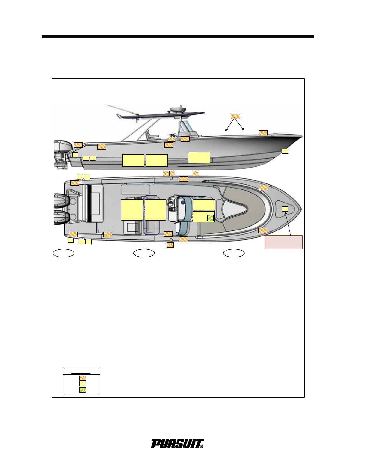
Specifications
Locate and Identify: identificar:Localizar e Localizzazione e identificazione dei
A
) Fuel Tank
A
) Depósito de Combustible componenti:
B) Fuel Tank Filling Point B) Punto de Carga del Depósito de
A
) Serbatoio carburante
C) Oil Tank (N/A) Combustible B) Bocchettone di riempimento
D) Oil Tank Filling Point (N/A) C) Depósito de Aceite (N/A) serbatoio carburante
E) Oil Tank Emptying Point (N/A) D) Punto de Carga del Depósito de C) Serbatoio olio (N/A)
F) Water Tank Aceite (N/A) D) Bocchettone di riempimento
G) Water Tank Filling Point E) Punto de Descarga del Depósito (N/A) serbatoio olio (N/A)
H) Holding Tank de Aceite E) Scarico serbatoio olio (N/A)
I) Holding Tank Emptying Point F) Depósito de Agua F) Serbatoio acqua
J) Seacocks G) Punto de Carga del Depósito de G) Bocchettone di riempimento
K) Through-Hull Fittings Agua serbatoio acqua
L) Fire Extinguisher H) Tanque de Tetención H) Cassa zavorra
M) Carbon Monoxide Detector (N/A) I) Punto de Descarga del
I) Scaric cassa zavorra
N) Escape Hatch (N/A) Tanque de Tetención J) Valvole di presa acqua dal mare
O) Fire Escapes (N/A) J) Válvula de Toma de Agua de Mar K) Raccorderia passante nello scafo
P) Life Raft Stowage K) Accesorios Pasantes del Casco L) Estintore
Q) Safety Equipment L) Extintor de Incendios M) Rivelatore monossido di carbonio
R) Anchor Strong Points M) Detector de Monóxido de carbonio (N/A)
S) Mooring Strong Points Carbono (N/A) N) Boccaporto di sfuggita (N/A)
T) Towing Strong Points (ST310) N) Escotilla de Seguridad (N/A) O) Uscite di sicurezza (N/A)
O) Escalera de Incendios (N/A) P) Stivaggio zattera di salvataggio
P) Almacenamiento de balsas Q) Dotazioni di sicurezza
salvavidas R) Punti di attaco per l'ancoraggio
Q) Equipos de seguridad S) Punti di attacco per l'ormeggio
R) Puntos fuertes de anclaje T) Punti di attacco per il traino (N/A)
S) Puntos fuertes de amarre
T) Puntos fuertes de remolque (N/A)
Specifications
1/22/2011
Model: ST310
EN ES ITEN ES IT
LEGEND
Deck Hull Head -
AA
AA
F
H
H
Cleat on windlass
beam
0B
14
C280 / S280 / C310 / ST310
Page 19
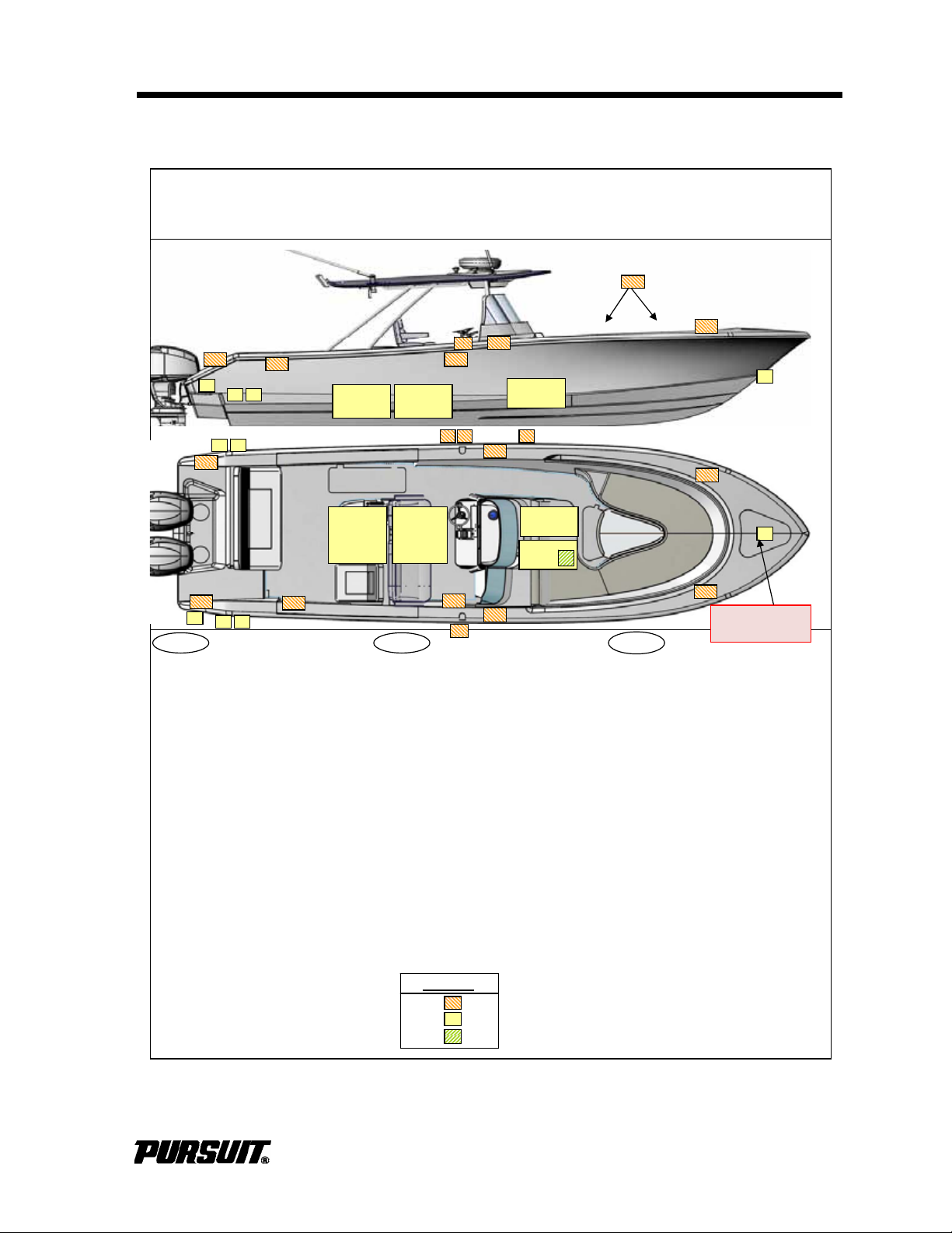
Specifications
Repèrez et identifiez: Position and Beschreibung: Localizar e Identificar:
A
) Réservoir de carburant
A
) Kraftstofftank
A
) Depósito de Conbustível
B) Point de remplissage réservoir B) Kraftstofftankfüllpunkt B) Ponto de Enchimento do Depósito de
de carburant
C)Öltank (n.z.)
Combustível
C) Réservoir d'huile (N/A
)
D)Öltankfüllpunkt (n.z.) C) Depósito de Óleo (N/A
)
D) Point de remplissage réservoir
E)
Ö
ltankablasspunkt (n.z.)
D) Ponto de Enchimento do Depósito de
d'huile (N/A
)
F) Wassertank
Ó
leo (N/A
)
E) Point de vindage réservoir G) Wassertankablasspunkt E) Ponto de Esvaziamento do Depósito
d'huile (N/A
)
H) Speichertank
de
Ó
leo (N/A
)
F) Réservoir d'eau I) Speichertankablaßpunkt F) Depósito de Água
G) Point de remplissage réservoir J) Flutventile G) Ponto de Enchimento do Depósito de
d'eau K) Rumpfdurchgangsanbauten
Á
gua
H) Réservoir de rétention L) Feuerlöscher H) Depósito Provisório
I) Point de vidange résevoir de
M) Kohlenmonoxiddetektor (n.z.)
I) Ponto de Esvaziamento do Depósito
rétention
N) Notausstieg (n.z.)
Provisório
J) Prises d'eau à la mer
O) Reuerrettungswege (n.z.)
J) Torneiras de tomada de àgua do mar
K) Raccords traversant la coque P) Rettungsfloßunterbringung K) Acessórios de Todo o Casco
L) Extincteu
r
Q) Sicherheitsausrüstung L) Extintor de Incêndios
M) Détecteur de monoxyde de R) Ankerpunkte M) Detector de Monóxide de
carbone (N/A
)
S) Vertäuungspunkte
Carbono (N/A
)
N) Ecoutille d'évacuation (N/A
)
T) Abschlepppunkte (n.z.) N) Escotilha de Fuga (N/A
)
O) Echelles de sauvetage N/A
)
O) Saídas de Incêndio (N/A
)
P) Arrimage du radeau de P) Acondicionamento do Barco
sauvetage Salva-vidas
Q) Equipement de sécurité Q) Equipamento de Segurança
R) Points d'ancrage R) Pontos Fortes da Ancoragem
S) Points d'amarrage S) Pontos Fortes da Amaragem
T) Points de remorquage (N/A
)
T) Pontos Fortes da Rebocagem (N/A
)
Specifications
1/22/2011
Model: ST310
FR DE
PT
LEGEND
Deck Hull Head -
AA
AA
F
H
H
Cleat on windlass
beam
0B
C280 / S280 / C310 / ST310
15
Page 20
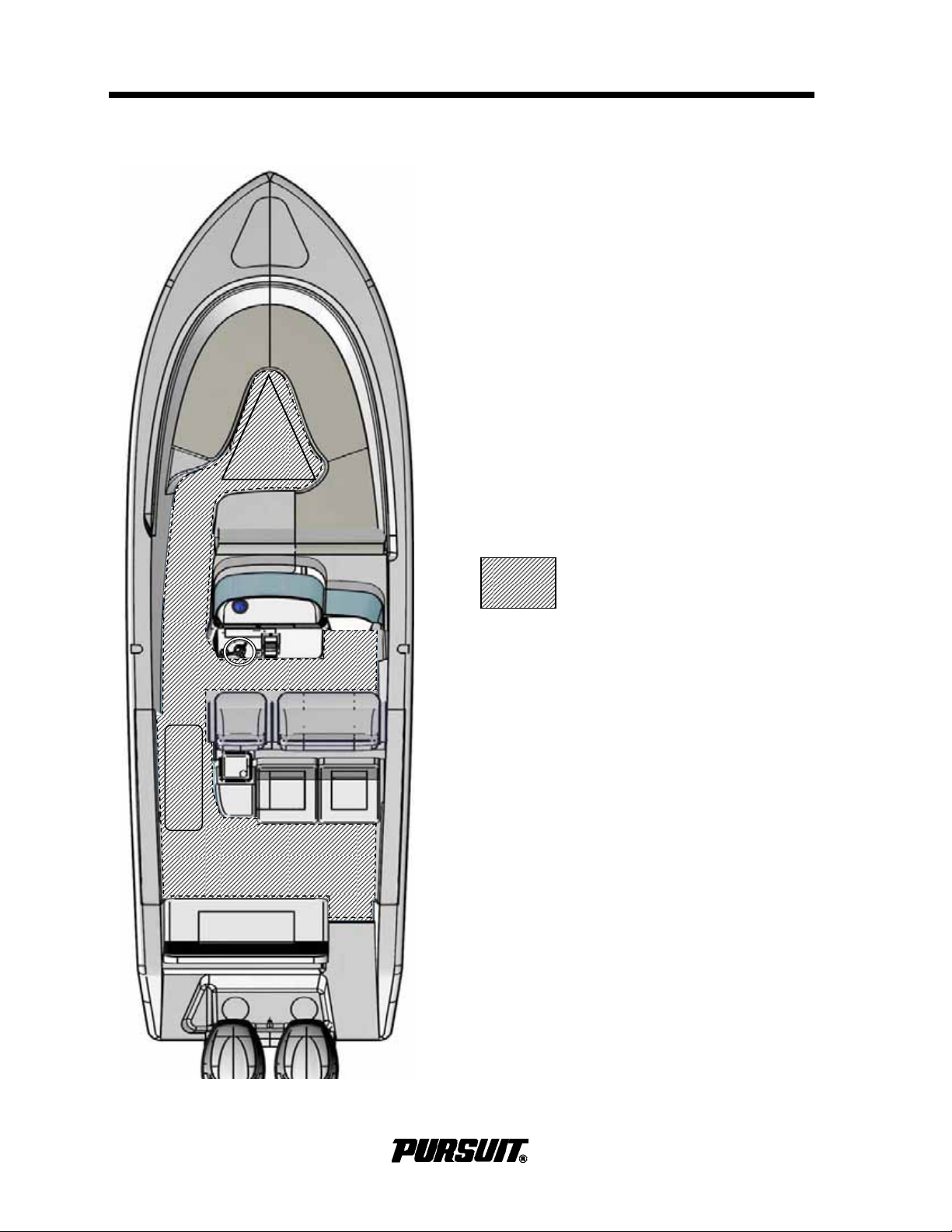
Specifications
Working Deck
Areas for occupation during normal
operation of the boat
Working Deck Area
1/22/2011
Model: ST 310
16
C280 / S280 / C310 / ST310
Page 21
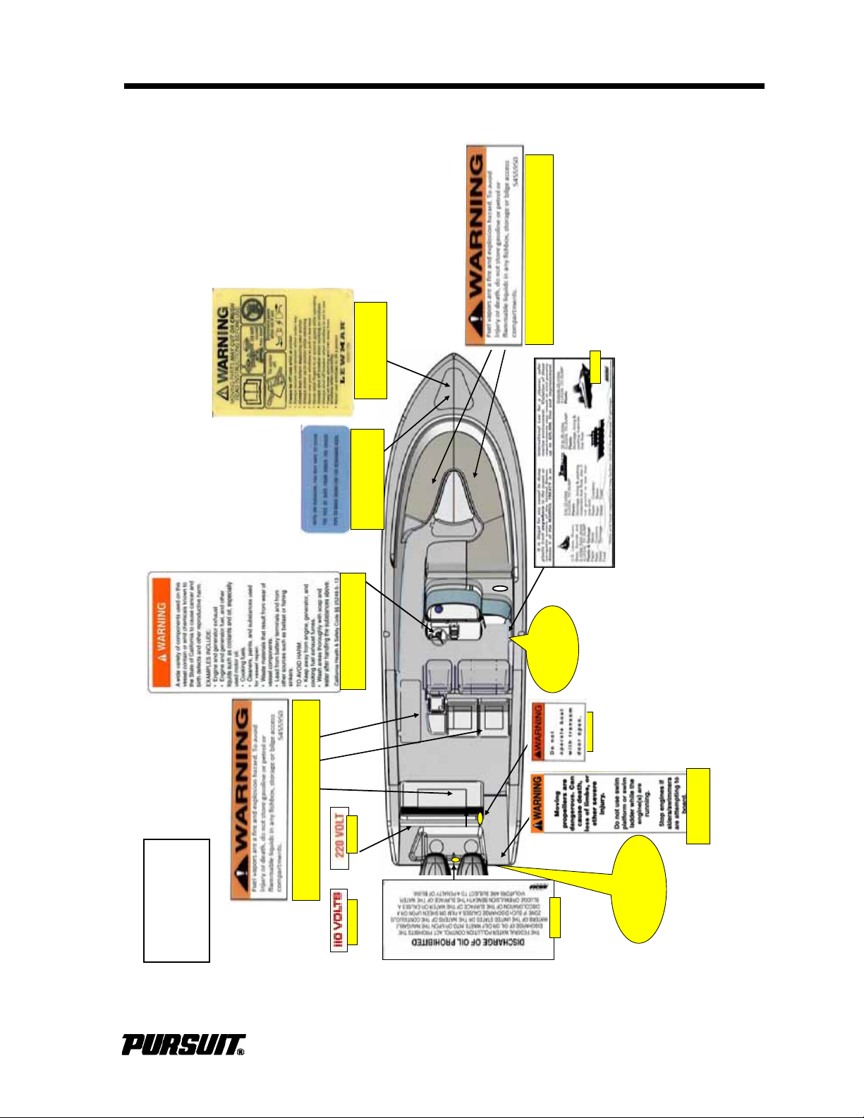
Specifications
Warning Label
Locations
ST310
5454490
5453550
Attached to the steering wheel
Detail A
Inside Stbd
Helm Wing
545450
5450170
o
r
5451750
A
ttached to the ladder
5450550
Detail B
Starboard Aft
Transom
5455970
Attached to the underside of
the anchor hatch
5455960
Attached to the underside of
the anchor hatch
5455950
Attached to the underside of the forward storage hatches
5455950
Attached to the underside of the aft storage hatches & fishbox
0B
C280 / S280 / C310 / ST310
17
Page 22
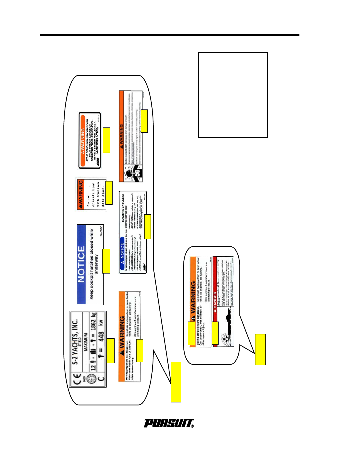
2/21/2011
5455990
5450060
5450120
5453690
5451180
Detail B
Detail A
Warning Label
Locations
ST310
5455660
Specifications
18
C280 / S280 / C310 / ST310
Page 23
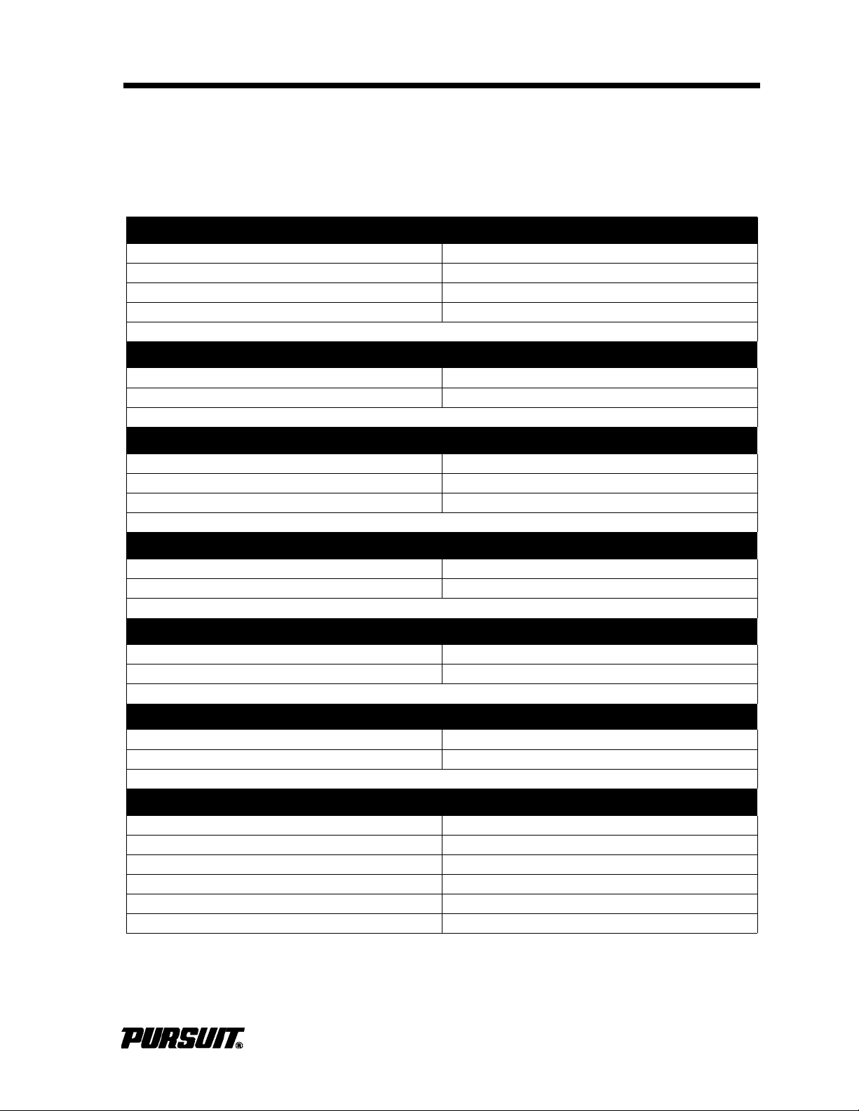
General Information
Boat Information
Fill out the following information and leave it in your PURSUIT Owner’s Manual. This
information will be important for you and PURSUIT service personnel to know, if and
when you may need to call PURSUIT for technical assistance or service.
Boat
Model: Hull Serial #:
Purchase Date: Delivery Date:
Ignition Keys # Registration #:
Draft: Weight:
Engine(s)
Make: Model:
Port Serial #: Starboard Serial #:
Transmission(s) (Inboard)
Make: Model:
Port Serial #: Starboard Serial #:
Ratio:
Outdrive(s) (Inboard/Outboard)
Make: Model:
Port Serial #: Starboard Serial #:
Propeller(s)
Make: Blades:
Diameter/Pitch: Other:
Generator
Make: Model:
Serial #: kW
Dealer Pursuit
Name: Phone:
Dealer/Phone: Representative:
Salesman: Address:
Service Manager:
Address:
PURSUIT Fishing Boats reserves the right to make changes and improvements in
equipment, design and vendor supplied equipment at any time without notification.
C280 / S280 / C310 / ST310
19
Page 24

General Information
Warranty and Warranty
Registration Cards
The PURSUIT Limited Warranty Statement
is included with your boat. It has been written to be clearly stated and easily understood. If you have any questions after
reading the warranty, please contact PURSUIT Customer Relations.
PURSUIT, engine manufacturers, and the
suppliers of major components maintain
their own manufacturer's warranty and service facilities. It is important that you properly complete the warranty registration cards
included with your boat and engine(s) and
mail them back to the manufacturers to register your ownership. This should be done
within 15 days of the date of purchase and
before the boat is put into service. A form for
recording this information is provided at the
beginning of this manual. This information
will be important for you and service personnel to know, if and when you may need service or technical information.
The boat warranty registration requires the
Hull Identification Number “HIN” which is
located on the starboard side of the transom,
just below the rub rail. The engine warranty
registration requires the engine serial number(s). Please refer to the engine owner's
manual for the location of the serial number(s).
Federal Boat Safety Act
All boat manufacturers are required by the
Federal Boat Safety Act of 1971 to notify first
time owners in the event any defect is discovered “which creates a substantial risk of
personal injury to the public.” It is essential
that we have your warranty registration card
complete with your name and mailing
address in our files so that we can comply
with the law if it should become necessary.
Product Changes
PURSUIT is committed to the continuous
improvement of our boats. As a result, some
of the equipment described in this manual or
pictured in the catalog may change or no
longer be available.
PURSUIT reserves the right to change
standard equipment, optional equipment
and specifications without notice or obligation. If you have questions about the
equipment on your PURSUIT, please contact PURSUIT Customer Relations.
Transferring the Warranty
For a Transfer fee, S2 Yachts will extend
warranty coverage to subsequent owners of
PURSUIT models for the duration of the
original warranty period. Please refer to the
PURSUIT Limited Warranty Statement for
the procedure to transfer the warranty. To
take advantage of this program, notification
of the change of ownership, including the
new owner's name, address and telephone
number together with the appropriate fee,
must be sent to PURSUIT Fishing Boats,
Customer Relations Department, 3901 St.
Lucie Boulevard, Ft. Pierce, Florida 34946,
within 30 days of the date of resale.
S2 Yachts will confirm, in writing, that the
transfer of the warranty has taken place.
After which, the transferee will be treated as
the original purchaser as outlined in the
PURSUIT Limited Warranty Statement.
Owner/Operator
Responsibilities
Registration and Documentation
Federal law requires all undocumented vessels equipped with propulsion machinery be
registered in the state of principal use. A certificate of documentation will be issued upon
registration. These registration numbers
must be displayed on your boat. The owner/
operator of a boat must carry a valid certificate of registration whenever the boat is in
use. When moved to a new state of principal
use, the certificate is valid for 60 days.
In order to be valid, the numbers must be
installed to the proper specifications. Check
with your dealer or state boating authority for
numbering requirements. The Coast Guard
issues the certificate of number in Alaska; all
others are issued by the state.
20 C280 / S280 / C310 / ST310
Page 25

General Information
Insurance
In most states the boat owner is legally
responsible for damages or injuries the boat
causes. Responsible boaters carry adequate liability and property damage insurance for their boat. You should also protect
the boat against physical damage and theft.
Some states have laws requiring minimum
insurance coverage. Contact your dealer or
state boating authority for information on the
insurance requirements in your boating
area.
Reporting Boating Accidents
All boating accidents must be reported by
the owner or operator of the boat to the
proper marine law enforcement authority for
the state in which the accident occurred.
Immediate notification is required if a person
dies or disappears as a result of a recreational boating accident.
If a person dies or there are injuries requiring more than first aid, a formal report must
be filed within 48 hours.
A formal report must be made within 10 days
for accidents involving more than $500.00
damage or the complete loss of a boat.
A "Boating Accident Report" form is located
near the back of this manual to assist you in
reporting an accident. If you need additional
information regarding accident reporting,
please call the Boating Safety Hotline, 800368-5647 or uscgboating.org.
ing Safety Hotline, 800-368-5647 or uscgboating.org for further information on boating
safety courses.
Required Equipment
U.S. Coast Guard regulations require certain
equipment on each boat. The Coast Guard
also sets minimum safety standards for vessels and associated equipment. To meet
these standards some of the equipment
must be Coast Guard approved. “Coast
Guard Approved Equipment” has been
determined to be in compliance with USCG
specifications and regulations relating to
performance, construction or materials. The
equipment requirements vary according to
the length, type of boat, and the propulsion
system. Some of the Coast Guard equipment is described in the Safety Equipment
Section of this manual. For a more detailed
description, obtain “Federal Requirements
and Safety Tips for Recreational Boats” by
contacting the Boating Safety Hotline 800368-5647, uscgboating.org or your local
marine dealer or retailer.
Some state and local agencies go beyond
USCG regulations or impose similar equipment requirements on waters that do not fall
under Coast Guard jurisdiction. Contact your
dealer or local boating authority, they can
provide you with additional information for
the equipment requirements for that boating
area.
Education
If you are not an experienced boater, we recommend the boat operator and other people
that normally accompany the operator, enroll
in a boating safety course. Organizations
such as the U.S. Power Squadrons, United
States Coast Guard Auxiliary, State Boating
Authorities and the American Red Cross
offer excellent boating educational programs. These courses are worthwhile even
for experienced boaters to sharpen your
skills or bring you up to date on current rules
and regulations. They can also help in providing local navigational information when
moving to a new boating area. Contact your
dealer, State Boating Authority or the Boat-
C280 / S280 / C310 / ST310
21
Page 26

Operator Notes
22 C280 / S280 / C310 / ST310
Page 27

Propulsion Systems
Section 1
Propulsion Systems
1.1 General
Your Pursuit boat is designed to be powered
with twin 2-cycle or 4-cycle outboard
engines.
Each manufacturer of the various outboard
engines provides an owner’s information
manual which includes its limited warranty
statement with its product. It is imp ort ant you
read and understand the information and
become familiar with the warranty, operation
and maintenance of the engines and drive
systems.
! NOTICE
DO NOT attempt to service any part of
the outboard or boat systems unless
you are familiar or qualified to do so.
Do not use parts which are not
designed for a marine application.
! WARNING
MOVING PARTS HAZARD.
Contact with moving parts can entangle, cut and cause death or serious
injury. DO NOT get close enough to
make contact with any running
machinery moving parts, i.e., engine
or propeller. Contact can result in loss
of body parts, strangulation, burns
and/or severe loss of blood resulting
in death or serious injury.
! NOTICE
Use only the fuel recommended by the
engine manufacturer. Use of old, contaminated fuel can cause the engine to
malfunction or severe damage.
1.2 Saltwater Application
Each outboard engine is a complete drive
system with the gear case (transmission)
forward of the propeller and connected to
the power head with a vertical drive shaft.
Other than the routine maintenance outlined
in the engine owner’s manual, there is little
to be concerned with unless the boat is to be
kept in saltwater for extended periods.
Marine growth will occur when components
are left in the water for extended periods and
can cause poor performance or permanent
damage to the exposed components. The
type of growth and how quickly it occurs is
relative to the water conditions in your boating area. Water temperature, pollution, current, etc. can have an effect on marine
growth.
Galvanic corrosion is the corrosion process
occurring when different metals are submerged in an electrolyte. Sea water is an
electrolyte and submerged engine components must be properly protected. Outboard
engines are equipped with sacrificial anodes
to help prevent galvanic corrosion problems.
The anodes must be monitored and
replaced as necessary. For locations and
maintenance, refer to the engine owner’s
manual.
When leaving the boat in the water, tilt the
motors as high as possible to decrease the
risk of marine growth around the cooling
inlets, propeller and exhaust ports and damage from galvanic corrosion.
C280 / S280 / C310 / ST310
1-1
Page 28

Section 1 Propulsion Systems
1.4 Engine Cooling System
! CAUTION
DO NOT use copper-based coatings
or any coatings not approved for use
with aluminum. Some paint manufacturers claim their paints are safe for
aluminum. Copper components and
copper-based paint s can cause severe
corrosion to aluminum. DO NOT use
copper-based paints.
cury-based compounds that come
into contact with aluminum will result
in severe corrosion.
Mercury or mer-
1.3 Engine Lubrication
Outboard engines are raw water (sea water)
cooled. Water is pumped through the water
inlets, circulated through the engine block,
and expelled with the exhaust through
exhaust port, water port and the propeller
hub. The water pump uses a small impeller
made of synthetic rubber. The impeller and
water pump cannot run dry for more than a
few seconds. In most outboard engines,
some cooling water is diverted through ports
below the engine cowling. This allows the
operator to visually check the operation of
the cooling system. When the engine is
started, make sure a steady stream of water
is present.
4-cycle engines have an oil sump in the
crankcase. The oil type, grade and level
must be followed in accordance with the
engine manufacturer’s recommendation. It is
normal for 4-cycle engines to consume a
small amount of oil. Check the oil level
before each use and change it following the
engine manufacturer’s recommendation.
2-cycle outboard engines are lubricated by
an oil injection system. Check the oil level
before each use and use only type specified
by the engine manufacturer. Also monitor
the oil level by checking the gauge in the
helm or visually checking the oil level in the
tank by using the reference marks on the
tanks. Refer to the engine owner’s manual
for oil specifications and additional information on the oil injection system. Refer to the
Fuel System Section.
! NOTICE
Use only the oil recommended by the
engine manufacturer, and monitor the
oil level. Use of any other type of oil
can cause the engine to malfunction
or severe damage.
! CAUTION
DO NOT operate an engine out of the
water, even momentarily. Water must
be supplied to the cooling system of
the power head and water pump, or
serious damage will result. If it is necessary to run the engine out of the
water, connect it to a engine flush
attachment design for your specific
engine.
If the boat is used in salt or badly polluted
water, flush the engines after each use to
reduce corrosion. Refer to the engine
owner’s manual for the proper engine flushing procedure.
1.5 Propellers
The propellers convert the power of the
engines into thrust. Propellers vary in style,
diameters and pitch. The best set for your
needs will depend on your application and
expected average load. Propeller sizes are
identified by two numbers stamped on the
prop in sequence; the first is the diameter
and the second is the pitch (example 14 x
21). Pitch is the theoretical distance the propeller will travel in one rotation. Repair or
replace a propeller immediately if it has been
damaged. A damaged propeller can cause
1-2
C280 / S280 / C310 / ST310
Page 29

Propulsion Systems
Section 1
vibration that can be felt in the boat and can
damage the engine gear case. Refer to the
engine owner’s manual for information on
propeller removal and installation.
1.6 Engine Instrumentation
The helm station is equipped with a set of
engine instruments and alarms. The instruments allow the operator to monitor the
operational conditions of the engines. Monitoring the instrumentation allows the operator to operate the engines most efficiently
and prevent serious costly damage. The
instrumentation is unique to the type of outboard engines installed on your Pursuit.
Your boat may not be equipped with all of
the following gauges.
Some models may be equipped with
Yamaha Command Link Integrated Information System®. Refer to the Yamaha
manuals for information on the operation
of this system.
Tachometer
Temperature Warning
The temperature warning indicates the temperature of the engine. A sudden increase in
the temperature could indicate an obstructed
water inlet or an impeller failure.
! NOTICE
Continued operation of an overheated
engine will cause severe engine damage. If the engine overheats, shut off
the engine, investigate the problem
and correct it.
Fuel Gauge
The fuel gauge indicates the approximate
fuel level in the fuel tanks. This gauge is a
relative indication of the fuel supply available; it is not a calibrated instrument. On
Yamaha equipped boats, fuel level is displayed in the speedometer.
The tachometer displays the speed of the
engine in revolutions per minute (RPM). This
speed is not the boat speed or the speed of
the propeller. The tachometer may not register zero with the key in the “OFF” position.
! NOTICE
DO NOT exceed maximum recommended engine RPM. Exceeding,
maintaining or close to maintaining
maximum can reduce engine life.
Speedometer
The speedometer indicates the speed of the
boat in miles per hour (MPH). Most speedometers measure the water pressure
against a small hole in a pick-up tube
located in the engine lower unit or from GPS
in a Yamaha® installation.
Voltmeter
The voltmeter displays the voltage for the
battery and the charging system. The normal voltage for a full charged battery is 12.6
volts with the engine(s) off and 13 to 14.5
volts with the engine(s) running.
Hourmeter
The hourmeter keeps a running total of
engine hours while operating.
Tilt/Trim Gauge
The tilt/trim gauge monitors the position of
the outboard engine. The upper range of the
gauge indicates the tilt, which is used for
shallow water operation, trailering and to
keep the gear case out of the water. The
lower range indicates the trim position. Trim
is used to adjust the hull angle while operating your boat on plane. Refer to the engine
owner’s manual for more information on the
operation of the outboard power tilt and trim.
C280 / S280 / C310 / ST310
1-3
Page 30

Section 1 Propulsion Systems
Engine Alarms
Most outboards are equipped with an audible alarm system mounted in the helm area
to monitor selected critical engine systems
and functions. The alarm will sound if one of
these systems begins to fail. Refer to the
engine owner’s manual for information on
the alarms installed with your engines.
! CAUTION
If an engine alarm sounds, shut off the
engine, investigate the problem and
correct it.
Fuel Management
Fuel management systems are standard
equipment with some outboard engines. On
Yamaha® engines, the fuel management
gauge is a multifunction gauge used to monitor fuel consumption of the engines. If your
boat is equipped with this system, refer to
the engine or fuel management manual.
Instrument Maintenance
Electrical system, instruments and ignition
circuitry are protected by a circuit breaker or
fuse located on the engine. The ignition
switches and all instruments, controls, etc.
must be protected from the weather when
not in use. Excessive exposure can lead to
gauge and ignition switch failures.
Moisture may fog the inside of the gauge
lens. Turning the gauge lights on will help
dry the lenses. Fogging will normally not
harm the gauges, but if the fogging continues and moisture accumulates, the excess
water can damage the gauges. The gauges
are designed with drain holes to reduce the
accumulation of moisture. Make sure that if
a gauge is removed, it is reinstalled with the
drain holes in the proper position.
1-4
C280 / S280 / C310 / ST310
Page 31

Helm Systems
Section 2
Helm Systems
2.1 General
The helm controls consist of engine throttle
and shift controls, steering system, trim tab
control switches and the optional spotlight
control.
Each manufacturer of the control components provides an owner’s manual with its
product. It is important that you read, understand and become familiar with the proper
care and operation of all control systems.
! WARNING
LOSS OF CONTROL AND UNSAFE
BOAT HAZARD
Hazard from improper securing of
helm is hazardous and can cause
death or serious injury from sudden
loss of control. Make sure the helm is
secure before getting underway and
during transporting the boat.
2.2 Engine Throttle and Shift Controls
The handles of dual lever controls may not
always align with each other at all RPM settings because of variations in the routing of
control cables, cable length and adjustments
at the engine. Usually the alignment of the
handles can be optimized at a chosen RPM,
but may vary at other settings.
! CAUTION
Avoid possible injury or engine damage when shifting:
• Pause in neutral before shifting
from FORWARD to REVERSE, or
REVERSE to NEUTRAL.
• DO NOT shift into reverse while
the boat is traveling forward at
speed.
• Keep area around shifter control
clear of obstructions.
See your Pursuit dealer for necessary control and cable adjustments. If the starter for
either engine engages with the shift controls
in any position other than neutral, the neutral
safety switch is not functioning properly and
must be repaired before using your boat.
2.3 Neutral Safety Switch
The shift and throttle controls on your boat
may vary depending on the engines. The following control description is typical to most
outboard remote controls. Refer to the
engine or control manuals for specific information on the controls installed on your Pursuit.
The helm on your Pursuit is designed for a
binnacle style control with a single gear shift
and a throttle lever for each engine; a position for neutral (straight up and down), forward position (first detent forward of neutral)
and reverse position (the first detent aft of
neutral). Advancing the control lever beyond
the shift range will advance throttle, forward
or reverse. Each control is equipped to allow
the engine to be operated above idle RPM
while in neutral for cold starting or warming
up.
Every control has a neutral safety switch to
prevent the engine from being started while
in gear. Control or cable adjustments must
be performed if the engine will start in forward or reverse.
Test the neutral safety switches periodically
to ensure they are operating. To test the
neutral safety switches; tilt the engines down
and move the shift levers to the forward
position, past first detent. DO NOT advance
past the idle position. Tu rn the ignitio n key to
the start position. The starter should not
engage for either engine. Repeat test with
the shift levers in reverse and the engine
throttles at idle, the starter should not
engage for either engine. If an engine starts
in gear during this test, immediately move
the control levers to the neutral position and
turn the engine off. Ejection or sudden loss
of control can occur if an engine can start in
gear and neutral safety switch system does
not function properly.
C280 / S280 / C310 / ST310
2-1
Page 32

Section 2 Helm Systems
! WARNING
Test the neutral safety switch periodically. If the switch is not operating
properly, DO NOT use the boat. Contact your Pursuit Dealer and have it
repaired. An inoperable neutral safety
switch can allow the engine to start in
FORWARD or REVERSE causing sudden boat movement, throwing the
operator and passengers off balance
and possibly overboard.
! WARNING
LOSS OF CONTROL AND UNSAFE
BOAT HAZARD
A neutral safety switch that does not
function properly can cause death or
serious injury. DO NOT operate the
boat if the switch does not function
properly.
2.4 Engine Power Tilt and Trim
All outboard engines used on your boat have
a tilt and trim feature. The tilt and trim
switches are usually built into the engine
shift and throttle controls and allow the operator to control the position of the outboards
from the helm. Moving the gear cases closer
to the boat transom is called trimming “in” or
“down.” Moving the gear cases away from
the boat transom is called trimming “out” or
“up.” In most cases, the boat will perform
best with the outboards adjusted so the hull
will run at a three to five degree angle to the
water.
The term “trim” generally refers to the adjustment of the outboards within the first 20
degree range of travel. This is the range
used while operating your boat on plane.
The term “tilt” refers to adjusting the outboards further up for shallow water operation, trailering or “tilting” the outboards out of
the water. Refer to the engine owner’s manual for information on the proper use and
maintenance of the power tilt and trim.
! CAUTION
The outboard hoses and cables or the
transom gel coat can be damaged if
the engine(s) are tilted to full up position or turned in the wrong direction.
Turn the steering wheel completely to
one direction or the other before tilting up to determined which direction
is best for your boat.
2.5 Engine Stop Switch
Your Pursuit is equipped with an engine stop
switch and lanyard. When the lanyard is
pulled away, it will shut off the engines.
! WARNING
LOSS OF CONTROL AND UNSAFE
BOAT HAZARD
An engine stop switch system that
does not function properly or is not
used can cause death or serious
injury. DO NOT operate the boat if the
emergency stop switch system does
not function properly.
Attach the engine stop switch lanyard to a
strong piece of clothing on the operator. The
engines will not start if the clip is not inserted
into the stop switch. Make sure the lanyard
is properly attached to the engine stop
switch before attempting to start the engine.
DO NOT use the switch to stop the boat
under normal operation. Test the switch periodically, if the switch is not operating properly, DO NOT use the boat. Contact your
Pursuit Dealer and have it repaired.
Refer to the engine owner's manual for more
information on the engine stop switch.
2-2
C280 / S280 / C310 / ST310
Page 33
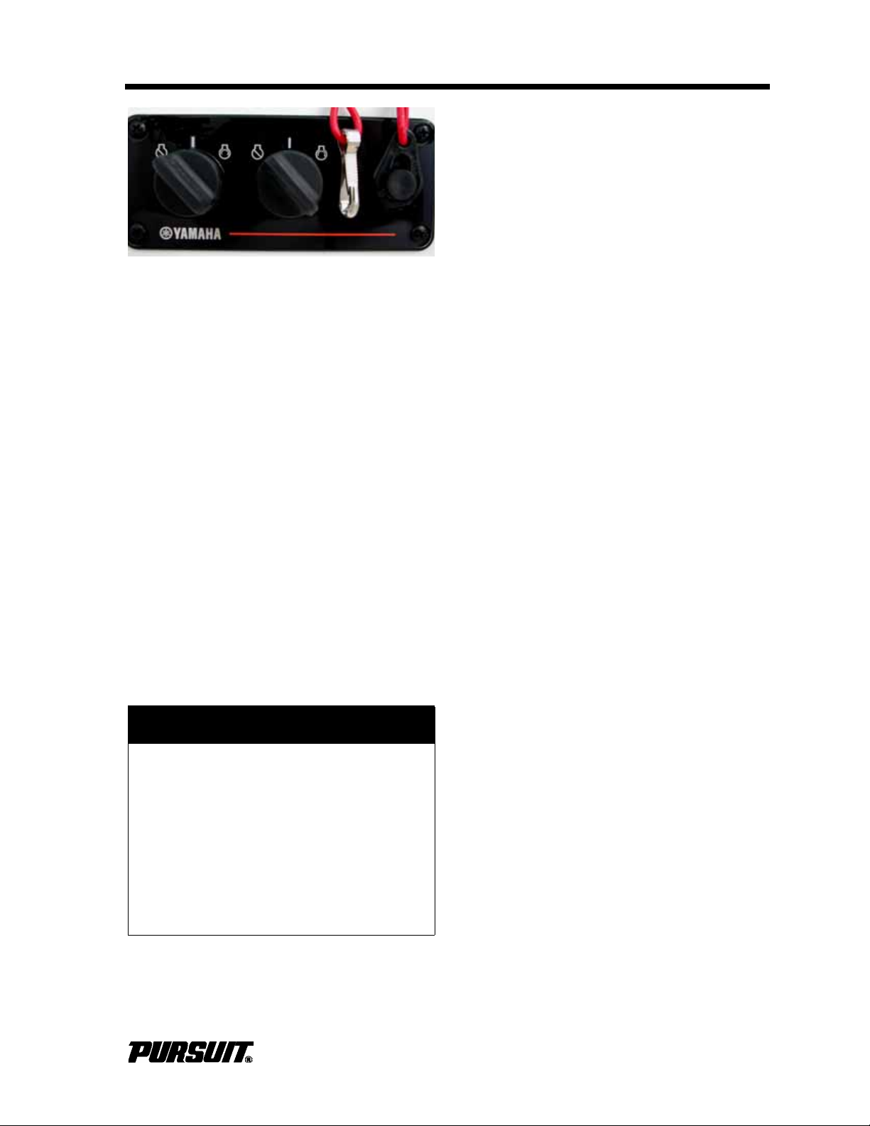
Helm Systems
Engine Stop Switch (Typical)
2.6 Steering System
The steering system is hydraulic and made
of two main components: the helm assembly
and the hydraulic cylinder. The helm unit
acts as both a fluid reservoir and pump.
Turning of the helm, or steering wheel,
pumps the fluid in the hydraulic hoses and
activates the hydraulic cylinder causing the
motors to turn. A slight clicking sound may
be heard as the wheel is turned. This sound
is the opening and closing of valves in the
helm unit and is normal. Refer to the steering manufacturer owner’s manual for specific information on the steering system.
Section 2
Power Steering (Optional)
The power steering system uses an electrically controlled hydraulic pump to provide
power to the standard hydraulic steering
system. Additional components are a helm
mounted power steering switch and a
hydraulic pump. The switch activates the
power steering feature. Manual steering is
always available regardless of the switch
position. To reduce the sensitivity of the
steering, turn off the power steering at low
speeds. To conserve battery power, because
of limited engine charging output during
extended periods of slow speed operation,
the power steering should be turned off.
Refer to the Teleflex® Power Assist manual
for more information.
Tilt Helm
A tilt helm, steering wheel may be installed
on your boat. To tilt the helm, depress the
lever located in the base of the helm and
lock into position. DO NOT adjust when the
boat is underway.
2.7 Trim Tabs
Dual engine outboards are coupled at the tiller arms by a tie bar. The outboards must be
aligned with each other to provide maximum
stability on straight ahead runs and proper
tracking through corners. If damage has
ever occurred with the outboards or steering
system, the outboards may have to be
realigned.
! CAUTION
Some autopilot systems have engine
position sensors mounted to the
hydraulic steering cylinder. The sensor bracket can contact the transom
when the engines are fully tilted up
and damage the autopilot, engine rigging or transom. Monitor the bracket
and rigging while engines are tilting to
determine the best position for your
application.
The trim tabs are recessed into the hull on
the transom. Switches are used to control
the trim tabs. The switches are labeled and
control bow up and down movements. They
also control starboard and port up and down
movements. Bow up and bow down will control the hull planning attitude, while port and
starboard up and down provide control for
the hull trim side to side.
Before leaving the dock, make sure that the
tabs are in the full “UP” position by holding
the control in the bow "UP" position for ten
seconds. Do not continue to operate the
switch when the tabs are fully up or down.
Establish the intended heading and cruise
speed before attempting to adjust the hull
attitude with the trim tabs. Always make
slight adjustments to reduce over adjustments. After stabilizing speed and direction,
move the trim tabs to achieve a level side to
side running attitude being careful not to
over trim.
After depressing a trim tab switch, always
wait a few seconds for the change in the trim
plane to take effect.
C280 / S280 / C310 / ST310
2-3
Page 34
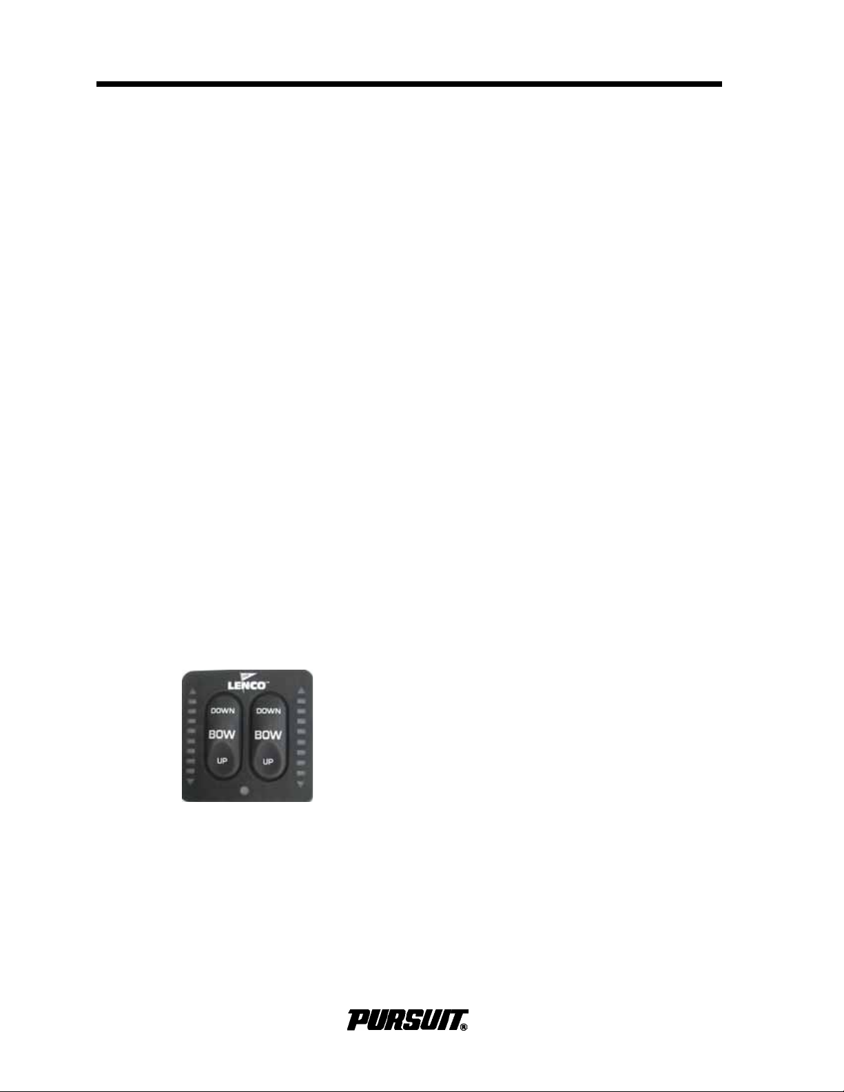
Section 2 Helm Systems
Trim Tab Switches
Avoid depressing the switch while awaiting
the trim plane reaction. By the time the effect
is noticeable the trim tab plane will have
moved too far and the boat will be in an
overcompensated position.
When running at a speed that will result in
the boat falling off plane, lowering the tabs
slightly, bow down, will improve the running
angle and operating efficiency. Too much
bow down tabs can reduce operating efficiency and cause difficult steering and handling.
When running at high speeds, make sure
the tabs are in the full “UP” position. Only
enough trim plane action should be used to
compensate for any listing. Trim tabs are
more sensitive at higher speeds. Adjust for
this and be prepared to slow down if difficulties arise.
Be extremely careful when operating in a following sea. The effect of trim tabs is amplified under these conditions. Difficulty in
steering and handling can result from
improper trim tab usage, especially in a following sea; raise the tabs to the full bow
"UP" position.
2.8 Compass
The compass is located at the helm. To
adjust the compass, read the instructions on
“Compass Compensation” included in the literature packet. The compass cannot be
adjusted accurately at the factory as it must
be compensated for the influence of the
electrical equipment and electronics unique
to your boat. The compass should be
adjusted by a professional after the electronics and additional electrical accessories are
installed and before operating the boat.
2.9 Spotlight (Optional)
The spotlight is controlled by a panel on the
helm and a microprocessor located under
the deck in the vicinity of the port hardtop
leg. Refer to the spotlight manufacturers
owner’s manual for an explanation of the
features and operation.
2.10 Control Systems Maintenance
When running into a chop, a slight bow
down attitude will improve the ride. Be careful not to over trim, difficulty in handling can
result.
Trim Tab Indicator
The switches are labeled to indicate the
reaction of the bow of the boat. The L.E.D.
displays indicate the position of the trim
tabs. When adjusting the starboard bow up
or down, the L.E.D. indicator on the right
side of the panel will activate, indicating the
movement of the port tab. Refer to the trim
tab operation manual.
Control Maintenance
Periodic inspection of the control systems
and all connections should be made. Signs
of rust, corrosion, wear, or other deterioration must immediately be serviced. Periodic
lubrication of all moving parts and connections with light waterproof grease is
required.
Control system adjustments may become
necessary. If adjustments are necessary,
see your Pursuit Dealer.
Steering System Maintenance
Periodically inspect all steering hoses, linkages and helm assemblies. Signs of corrosion, cracking, loosening of fastenings,
excessive wear, or deterioration must be
corrected immediately. Check the hydraulic
steering fluid level frequently and maintain
the proper level. Periodic lubrication of all
moving parts and connections with light
waterproof grease is required. Failure to do
so can lead to steering system failure and
result in loss of control.
2-4
C280 / S280 / C310 / ST310
Page 35

Helm Systems
When new, or after repairs, hydraulic steering systems may need to be purged of air.
Refer to the information provided with the
steering system for specifications and service information. Check steering operation
and visually inspect for loose or missing
hardware before operating the boat. If you
suspect the steering system is damaged,
see your Pursuit dealer. DO NOT operate
the boat if you suspect the steering system
is malfunctioning.
! WARNING
LOSS OF CONTROL AND UNSAFE
BOAT HAZARD
Improper maintenance of steering
system is hazardous and can cause
death or serious injury from sudden
loss of control. Make sure all steering
hardware, cables and fluid levels are
regularly inspected and maintained.
DO NOT attempt to service any part of
the steering system unless you are
familiar or qualified to do so. Follow
all instructions regarding maintenance procedures in the steering system owner’s manual.
Section 2
Trim Tab Maintenance
Marine growth can affect the operation of the
trim tab planes and actuators. To help
reduce marine growth, return the trim tabs to
the full “UP” position after operating the
boat. Inspect and clean the actuators and
planes regularly.
The trim tabs also include a zinc anode to
help prevent galvanic corrosion. Galvanic
corrosion occurs when different metals are
submerged in an electrolyte. Sea water is an
electrolyte and submerged metal components must be protected. Anodes were factory installed and need to be replaced when
they are 75% of their original size.
Refer to Routine Maintenance for information regarding zinc anodes and the trim tab
owner’s manual for additional maintenance
information, fluid specifications and operating instructions.
C280 / S280 / C310 / ST310
2-5
Page 36

Operator Notes
2-6 C280 / S280 / C310 / ST310
Page 37
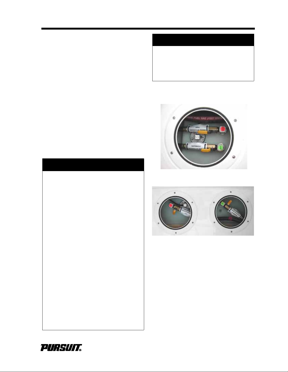
Fuel System
Fuel Valves Forward Tank
Fuel Valves Aft Tank
Section 3
Fuel Systems
3.1 General
The fuel system of your Pursuit boat is
designed to meet the requirements of the
U.S. Coast Guard, National Marine Manufacturers Association (NMMA), and American Boat and Yacht Council (ABYC) in effect
at the time of manufacture.
The fuel system was factory inspected and
pressure tested in accordance with regulations in effect at the time of manufacture. It is
the responsibility of the boat owner to maintain the safe condition of the system.
Inspect the system frequently to ensure no
deterioration or loosening of connections
has occurred.
! DANGER
! NOTICE
Certain bulkhead areas are sealed following U.S. Coast Guard regulations
at the date of manufacture. Any modifications must be in accordance with
the regulations.
3.2 Fuel System
FIRE/EXPLOSION HAZARD
Fuel and their vapors are highly explosive when exposed to open flame or
spark, resulting in death or serious
injury.
• Make sure no vapors are present
before turning on electrical equipment or starting engines.
• Make sure fuel is added to the fuel
tank only. DO NOT confuse other
deck fills with fuel fills.
• DO NOT remove anti-siphon
valves from the system.
• Turn off all electrical switches
before servicing the fuel system.
• DO NOT drain any fuel in the bilge.
• Check all fuel lines and fittings for
leaks before and after starting the
engines and after any fuel system
service.
• Prime fuel system and check all fit-
tings for leaks before and after
starting the engines.
• DO NOT block fuel vents.
• DO NOT store fuel in any contain-
ers or compartments not designated for fuel storage.
The fuel system on your Pursuit boat has
two fuel tanks and four manual “ON/OFF”
fuel valves. Refer to the Schematics section.
The fuel valves for the aft tank are located
through the hatch in the cockpit floor and the
fuel valves for the forward tank are located
through a deck plate forward of the leaning
post. The valves are off when the handle is
perpendicular to the fuel flow. The fuel
valves allow the operator to run the engines
from both tanks or from the aft tank or forward tank.
C280 / S280 / C310 / ST310
3-1
Page 38

Section 3 Fuel System
Operating the boat with all four, fuel valves
open, is not recommended and should be
avoided. The engines will not draw fuel
equally from the fuel tanks when both
engines are operating from both tanks The
fuel delivery lines are equipped with antisiphon valves where the lines attach to the
fuel tanks. These valves help prevent gasoline from siphoning out of the fuel tank
should a line rupture.
All boats equipped with gasoline engines are
required to have anti-siphon valves by the
U.S. Coast Guard. DO NOT remove antisiphon valves from system. Anti-siphon
valves prevent fuel from flowing into bilge
should a fuel hose or fitting leak. If the valve
becomes clogged, clean and reinstall or
replace it.
3.3 Fuel Management
C 280 and S 280
The port fuel fill, feeds the forward tank. The
starboard fuel fill, feeds the aft tank. During
normal operation, the port engine fuel supply
is from the forward tank and the starboard
engine fuel supply is from the aft tank. The
fuel valves on each tank are labeled port
(red) and starboard (green). The labels refer
to the engine the valves supply. If a fuel supply problem should occur, both engines can
be operated from either fuel tank by opening
both valves on that tank. In the event a fuel
supply problem should occur, resolve the
problem immediately. Operating the engines
on one tank should be done temporarily,
since the engines will consume from the
selected fuel tank only.
C 310 and S 310
On the C310 the port fuel fill, feeds the aft
tank and the starboard fuel fill, feeds the forward tank. On the ST310 both fills are on
the port side and match the orientation of the
fore and aft tanks. During normal operation,
the port engine fuel supply is from the aft
tank and the starboard engine fuel supply is
from the forward tank. The fuel valves on
each tank are labeled port (red) and starboard (green). The labels refer to the engine
the valves supply. If a fuel supply problem
should occur, both engines can be operated
from either fuel tank by opening both valves
on that tank. In the event a fuel supply problem should occur, resolve the problem
immediately. Operating the engines on one
tank should be done temporarily, since the
engines will consume from the selected fuel
tank only.
ST310
The fuel fills are on the starboard gunwale.
Their orientation matches that of the tanks,
i.e. the forward fill feeds the forward tank
and the aft fill feeds the aft tank.
Fuel Tanks
The fuel pick-up tubes are positioned in the
tanks to achieve optimum fuel usage, fuel
line routing, etc. At certain speeds and hull
trim angles, the fuel supply at the withdrawal
tube can increase or decrease accordingly.
Be extremely careful when attempting to
operate the boat when low on fuel. Though
some fuel may be in the tank, the trim angle
of the boat may cause the fuel to flow away
from the pickup tubes.
3-2
Fuel Gauge Senders
The fuel gauge senders are more accurate
when the boat is stationary and level.
Because of the change in attitude when the
boat is underway, variations in gauge readings can occur. Th is system is a relative indication of the available fuel supply and not a
calibrated instrument.
C280 / S280 / C310 / ST310
Page 39
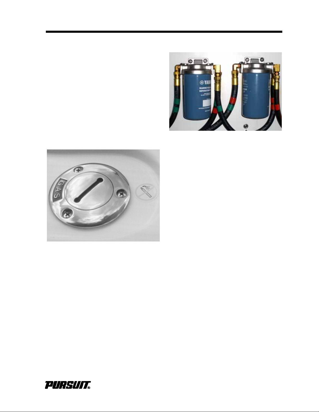
Fuel System
Fuel Fill
Section 3
Fuel Fills
A fuel fill deck plate is located on each gunwale and is marked “GAS.” The fuel fill is
opened by turning it counterclockwise with a
special key. After fueling, install the fuel cap
and tighten with the key; DO NOT over
tighten. Use only the fuel recommended by
the outboard manufacturer; refer to the
engine owner’s manual for additional information.
If fuel is added to any other tank, DO NOT
attempt to pump fuel out; these systems are
not designed to pump fuel. Fuel must be
removed by qualified personal only. Fuel in
other systems will also require replacement
of that system and/or many components.
Fuel Filters
Fuel Filters
Fuel filters are located in the machinery
space. The filters are the water separator
type and there is one filter for each engine
fuel line. Check both filters for water frequently to ensure an adequate supply of
clean, dry fuel to the engines. The filter elements should be changed once a season.
Fuel primers are also built into the top of
each fuel filter.
Fuel Vents
There are two fuel vents for the fuel tanks,
one on each side of the hull. While the tank
is being filled, air displaced by the fuel will
escape from the vents. Do not allow fuel to
be expelled from the vents and pollute our
environment. Fill the fuel tanks slowly and
monitor the fuel gauges while filling. Spilled
fuel can be dangerous.
Wash the areas around the fuel fill plates
and below the fuel vents to help reduce discoloration of fiberglass or striping.
Turn off all electrical switches before servicing the fuel system and DO NOT drain any
fuel into the bilge. Check all fuel lines and fittings for leaks before and after starting the
engines and after any fuel system service.
Prime fuel system and check all fittings for
leaks before starting the engines.
C280 / S280 / C310 / ST310
3-3
Page 40

Section 3 Fuel System
3.4 Fueling Instructions
! DANGER
FIRE/EXPLOSION HAZARD
Gasoline vapors are highly explosive
when exposed to open flame or spark,
resulting in death or serious injury.
• Stop engines before fueling.
• DO NOT smoke or allow open
flames or sparks nearby, within 50
ft (15 m) of the fueling area.
• Maintain contact between fuel noz-
zle and fuel tank fill to prevent
electrostatic spark. DO NOT use a
plastic funnel.
• Fill in an open area.
BURN HAZARD
Fuel floating on water which is ignited
can cause death or serious injury.
Fuel will float on top of water and can
burn. If the boat is abandoned, swim
upwind, far enough to avoid fuel that
can spread over the surface of the
water.
Try not to spill fuel. If fuel is spilled, wipe up
all traces with dry rags and immediately dispose of the rags properly onshore. DO NOT
allow fuel to stay on the finish of the boat,
discolor and damage to trim can occur.
Avoid fueling at night, except under welllighted conditions. Also, monitor fuel level
gauge to avoid overfilling.
To fill fuel:
• Turn all switches to "OFF."
• Secure boat.
• Remove passengers from boat.
• Extinguish all flame producing items.
• Open fuel fills with fuel fill key, counterclockwise.
• Put nozzle in the fuel fill opening.
• Fill the fuel tanks slightly less than
rated capacity to allow for expansion.
• Remove the nozzle.
• Install and tighten fuel cap. Do not to
overtighten.
Check the fuel compartment and below the
deck for fuel odors. If you smell fuel, DO
NOT start engines.
! DANGER
FIRE / EXPLOSION HAZARD
Fuels are extremely flammable and
highly explosive under certain conditions. DO NOT smoke or allow open
flames or sparks nearby when
inspecting the fuel system.
Frequently check fuel lines and all
system components (filters, primer
bulbs, clamps and connections) for
leaks, damage or deterioration, or if
you suspect damage, replace as necessary. Surface cracking on a hose
indicates wear. Replace it.
! CAUTION
Use only the fuel recommended by the
engine manufacturer. Use of old, contaminated fuel can cause the engine to
malfunction or severe damage. Do not
use fuel that contains more than 10%
ethanol, harsh additives or methanol;
damage to the engines and fuel system will result. Fuel system damage,
related to use of alcohol-blended
fuels, is not covered by the Pursuit
Limited Warranty. Refer to the engine
owner's manual for specific fuel
requirements for your engines.
3-4
Spray the valves, fuel tank gauge sender
and ground connections with a metal protector.
Inspect the fuel fill cap o-ring seals frequently and lubricate with petroleum jelly or
silicone grease. The o-ring seal prevents
water from entering the fuel system through
the fuel fill cap. If the o-ring is damaged, or
you suspect it is damaged, replace it.
C280 / S280 / C310 / ST310
Page 41

Fuel System
Old, degraded gasoline can affect engine
performance and damage the engine and
boat fuel system. Chemical changes occur
as gasoline ages, reducing octane and can
cause deposits and varnish in the fuel system.
If your boat is not operated enough to
require at least one full tank of fresh fuel a
month, a fuel stabilizer should be added to
the gasoline to protect the fuel from degrading. Do not allow the boat to sit unused for
an extended period with the fuel tanks less
than 3/4 full. Changes in temperature and
weather conditions can cause condensation
in fuel tanks. Your Pursuit dealer or the
engine manufacturer can provide additional
information on fuel degrading and fuel stabilizers recommended for your engine.
Improper storage of fuel at marinas, limited
boat usage, etc. can cause the fuel to
become contaminated. Periodically, it may
be necessary to pump accumulating water
and contaminated fuel from the bottom of
the fuel tanks. If the fuel system on your boat
becomes contaminated, contact your dealer
or marina for assistance.
Section 3
Avoid using fuels with alcohol additives.
Alcohol blend gasoline will absorb moisture
from the air which can reach such concentrations that "phase separation" can occur
where the water and alcohol mixture
becomes heavy enough to settle out of the
gasoline to the bottom of the tank. Since the
fuel pickup tubes are near the bottom of the
tank, phase separation can cause the
engine to run very poorly or not at all. Phase
separation is more severe with methyl alcohol and will increase as the alcohol content
increases. Water or a jelly like substance in
the fuel filters is an indication of phase separation from the use of alcohol blended fuels.
Diesel engine operation requires a good
supply of clean, water-free diesel fuel. Algae
can grow in the accumulated water in the
diesel fuel tank. This will normally occur in
warm climates. Adding a high quality diesel
fuel additive containing an algaecide periodically may be required to control algae in
your diesel system, depending on your boating area. Contact your Pursuit Dealer or
engine manufacturer for additional information regarding fuels and additives.
C280 / S280 / C310 / ST310
3-5
Page 42

Operator Notes
3-6
C280 / S280 / C310 / ST310
Page 43

Electrical System
Section 4
Electrical Systems
4.1 General
Your Pursuit boat is equipped with DC and
an optional AC electrical systems. The DC
system draws current from onboard batteries. The AC system can draw current from
either shore power outlets at dockside or the
optional generator.
Electrical schematics are included in this
manual to assist technicians in the servicing
the electrical systems. Pursuit recommends
you take your boat to an authorized Pursuit
dealer for service or installation of additional
electrical equipment. Pursuit reserves the
right to modify or update the electrical system at any time without notice to the consumer or obligation to make updates to
boats built prior to the change.
Some compartments on your boat may be
lighted. Lights bulbs produce heat and can
ignite combustible products. T u rn of f a ll lighting before you leave the boat.
! WARNING
FIRE OR EXPLOSION HAZARD
Ignited combustible products can
cause fire or explosion, resulting in
death or serious injury. DO NOT store
combustibles near lights and turn off
all lighting before leaving the boat.
4.2 DC System
Batteries
The 12-volt batteries have been selected to
provide optimum performance for engine
starting, and house and electronics loads.
There are three, Group 31, lead acid batteries; one for the starboard engine, one for the
port engine, and a house battery. These batteries require similar maintenance to automobile batteries. The batteries are located in
the aft bilge. A circuit breaker on each
engine protects the engine ignition systems
and gauges. Refer to the engine owner's
manual for information on the circuit breakers installed on your engines.
DC Distribution
The 12-volt DC system batteries are
charged by the engine charging system or
the battery charger when connected to the
optional shore power. The 12-volt DC power
is distributed to the battery switches and the
circuit breakers on the Main Distribution Panel
(MDP), located in the aft, starboard cockpit.
These circuit breakers protect the switch panels that are located on the helm and in the
head enclosure.
The circuit breaker on each engine protects
the engine ignition systems and gauges.
Refer to the engine owner's manual for information on your engines.
C280 / S280 / C310 / ST310
4-1
Page 44
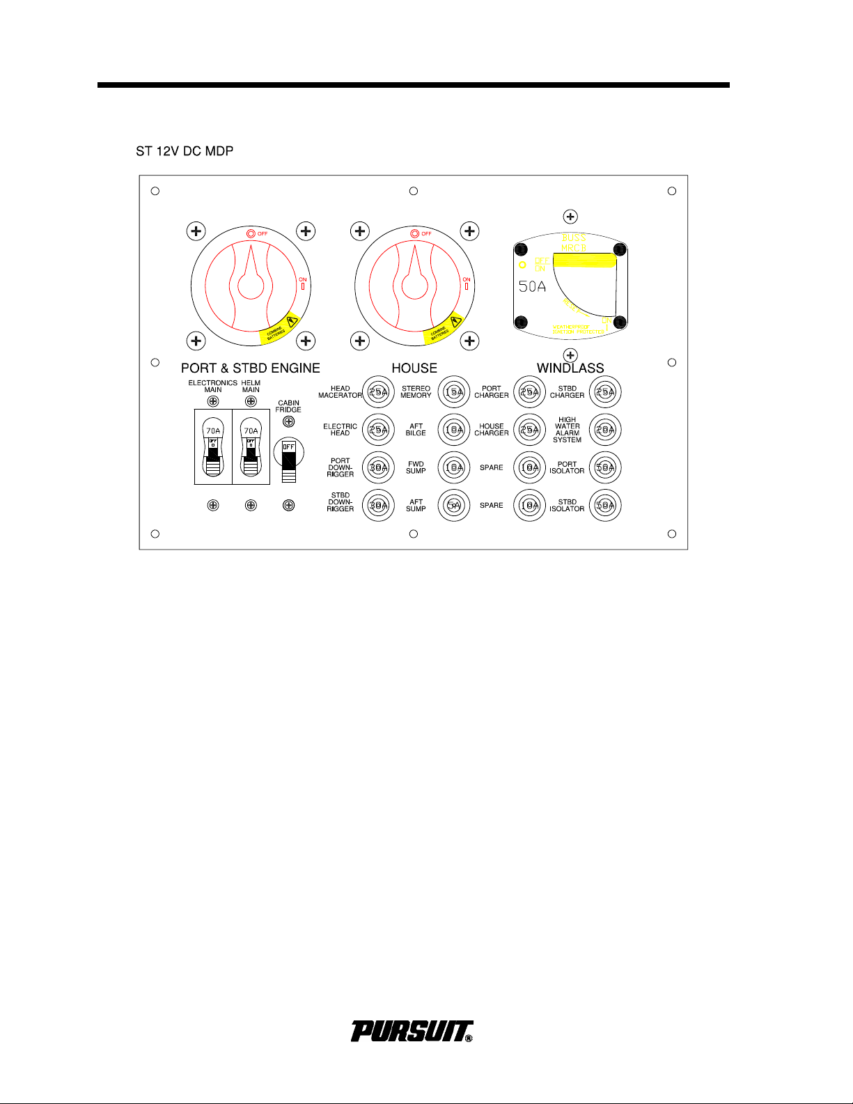
Section 4 Electrical System
Main Distribution Panel (MDP) Typical
Main Distribution Panel (MDP)
4-2
C280 / S280 / C310 / ST310
Page 45

Electrical System
Section 4
Battery Switches
There are two battery switches to manage
the 12-volt power distribution. One battery
switch controls both engine batteries. The
other battery switch controls the house battery. The port and starboard batteries can be
paralleled by switching the engine battery
switch to "combine batteries." It is possible
to parallel the engine batteries with the
house battery by placing both battery
switches in the “combine batteries” position.
Make sure the house and the battery
switches for the engines are in the "ON"
position whenever the engines are running
to ensure ALL 12-volt accessories will operate when they are needed. Current is supplied to the CO detector, the automatic float
switches for the bilge pumps, and the stereo
memory, when the batteries are connected
and the battery switches are "OFF".
! CAUTION
DO NOT operate the boat with the
engine battery switch in the combine
batteries position.
4.3 Main Breakers
S 280 and S 310 only – Refrigerator
The refrigerator is controlled by a toggle
style breaker, it can be turned ON or OFF
when selected.
Other Breakers
All remaining devices and circuits are protected by '' ‘PUSH to reset’ breakers that are
in the normally in the ON position. If a
breaker trips, reset by pressing the plunger.
Each breaker is labeled with the name of the
device it protects.
The stereo memory and aft bilge pump float
switch are always ON.
Bilge pumps and bilge pumping systems are
not designed for damage control. Make sure
all bilge pumps are functioning at regular
intervals. Debris can also prevent the pumps
from functioning or operate continuously.
Make sure no debris is blocking the bilge
pump float(s). Continuous operation of the
bilge pumps can mean a leak or a drain plug
is installed incorrectly, make sure all drain
plugs are installed.
Power to the stereo is supplied by the stereo
breaker located on the helm panel. The forward and aft sump breakers are not used.
Electronics Main
These are reserved for electronic accessories installation. An electronic bus is located
behind the helm.
Helm Main
Supplies the 12-volt current to helm panel.
Windlass (Optional)
The windlass breaker is located on the MDP.
Push the red button to open the circuit
breaker. To reset or turn the circuit breaker
on, rotate the black lever to "ON." Turn off
this breaker when the windlass is not in use
to reduce the possibility of accidentally activating the windlass.
C280 / S280 / C310 / ST310
Breakers also protect the battery charger
wiring, engine charging isolator wiring, the
electric head and the holding tank macerator. If you experience a battery-charging
problem, check the charger and engine isolator breakers and reset as necessary.
Downrigger circuits, are protected by a 30
Amp breaker. For aftermarket installation,
wiring is provided and routed to the port and
starboard gunwales, just aft of the gunwale
boards. The proper and correct terminals,
must be provided by the installer for the
equipment selected for installation,
4-3
Page 46
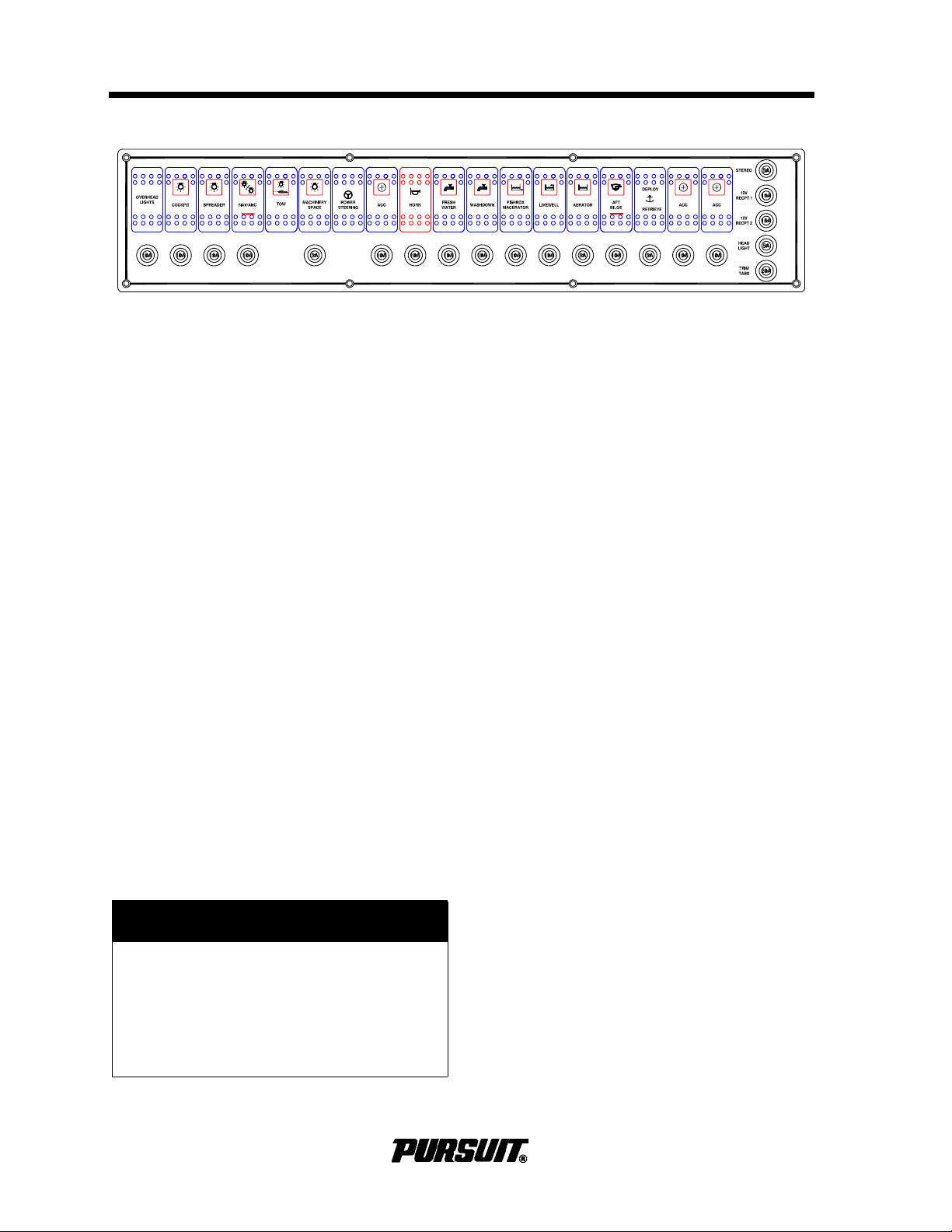
Section 4 Electrical System
Helm Panel
4.4 12-Volt DC Panels Helm
Helm Panel
The helm panel is equipped with switches and
circuit breakers. The breakers are in the normally "ON" position. Should any of the breakers trip, reset by pressing the plunger. If the
breakers continue to trip,
authorized Pursuit dealer to investigate the
problem.
components controlled by the helm switches:
The following are descriptions of the
take your boat to an
Overhead Lights
Press to activate the lights mounted underneath the hardtop. Press once and the lights
are red; press again and the lights are bright
white; press a third time and the lights are
dim white. If lights get out of sequence,
press the switch and hold for two seconds.
Cockpit
Press to activate the lights that illuminate the
cockpit area.
Spreader
Press to activate the flood lights located on
the hardtop.
Nav/Anc
Press the top of the rocker switch to activate
the navigation lights. Press the bottom of the
rocker switch to activate the anchor light.
Panel
Press to activate the instrument lights. The
compass light is also controlled with this
switch.
Machinery Space
Press to activate the light in the machinery
space.
Power Steering
Press to activate the power steering feature.
Tow Lights
Operates the required lighting for a boat
under tow. The Tow Lights should be operated when a boat is under tow. This lighting
arrangement meets the International Rules
of the Road standard. The indicator light on
the Nav/Anc will light but this switch must
remain off while the boat is under tow.
! CAUTION
Halogen lighting contains a filament
bulb that generates intense heat, is
pressurized and could shatter if
scratched or damaged. Protect glass
halogen-cycle bulbs from contact with
liquids when operating.
4-4
Underwater Lights (Optional)
Press to activate the underwater lights. DO
NOT use these lights out of the water. Water
is necessary for cooling.
Horn
Press to activate the horn.
C280 / S280 / C310 / ST310
Page 47

Electrical System
Section 4
Fresh Water
Press to activate the fresh water pump.
Washdown
Press to activate the raw water washdown
pump. The pump is a pressure demand type
and is protected by a circuit breaker on the
helm panel and an automatic reset breaker
in the pump motor.
Refer to the Plumbing Systems Chapter for
more information on the livewell and washdown systems.
Fishbox Macerator
The fishbox macerator switch activates the
overboard macerator discharge system for
the fishbox. The pump is protected by a circuit breaker on the MDP.
Livewell
Deploy Retrieve
Pressing the rocker switch deploys and
retrieves the anchor. Refer to the Windlass
in the Exterior Equipment.
Trim Tabs Panel
Bow Down/Up
This switch controls the trim tab planes
located on the transom of the boat. Refer to
the Helm Systems Chapter for detailed information on the operation of the trim tab controls.
Head Compartment Switch
Panel
These switches are protected by breakers
on the MDP.
Electric Head (Optional)
C 280, C 310 – standard, S 310
(optional)
Press to activate the livewell circulation
pump to supply water to the livewell. The
pump is protected by a circuit breaker on the
helm panel and an automatic reset breaker
in the pump motor.
Aerator
C 310 standard and S 310 – standard
with optional Livewell
If the livewell option is chosen, press this
switch to operate the aerator pump. Refer to
the Livewell Section of the Plumbing Systems Chapter.
Aft Bilge
Press to activate the manual pump. If the
automatic pump activates, the automatic
bilge pump indicator on the switch will light.
See Section 5.4, Bilge Drainage, for information on bilge pump operation.
Operates the electric head. Refer to the
head owner's manual for operating instructions.
Head Macerator
Press to activate the macerator for the holding tank, overboard discharge system. Refer
to the Interior Equipment Section of this
manual for additional information. This
breaker should be in the "OFF" position
except when pumping out the holding tank.
C280 / S280 / C310 / ST310
4-5
Page 48
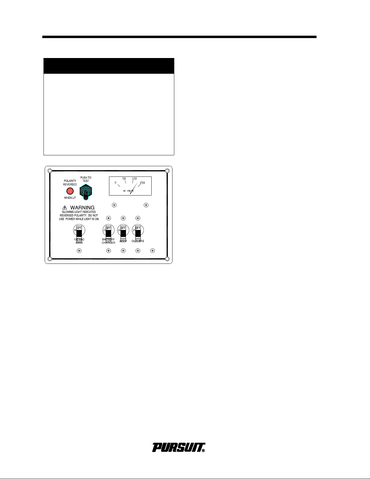
Section 4 Electrical System
AC Breaker Panel (Typical)
4.5 AC System
! DANGER
ELECTROCUTION, FIRE OR
EXPLOSION HAZARD
Contact with live wires or working on
an energized electrical system can
cause electrocution. It can also cause
sparks, resulting in fire and/or explosion. Both cases will result in death or
serious injury. DO NOT work on an
energized system or allow unqualified
personnel to work on the system.
Make sure the AC ground system is functioning properly and a proper connection
exists between the shore power cord and
power inlet, the boat bonding system and
the outlet ground circuits. If there is any
doubt about the integrity of the ground circuit, disconnect the AC, contact a qualified
marine electrician and repair.
To reduce the risk of electrical shock, avoid
making contact with the shore cable or making a connection to a live shore outlet, especially in wet conditions. DO NOT spray water
on electrical cables while washing down
decks.
4.6 AC Main Distribution
The AC panel is located in the console. The
following are descriptions of the AC panel
equipment and the breakers that protect the
accessories:
AC Volt Meter
The AC System is standard on the S 280
and S 310 and optional on the C 280 and
C 310. The AC system is fed by the shore
power connection and is equipped with onboard galvanic isolation.
The AC current is distributed to the AC
accessories through individual circuit breakers located in the AC panel. The main
breaker in the panel protects the system
from an overload and the reverse polarity
light indicates problems due to an improper
shore power supply. AC outlets are protected by ground fault circuit interrupters
(GFCI) to protect against electrical shock. A
cord set is provided to supply power from
the shore power outlet to the AC shore
power inlet of the boat.
Indicates the voltage supplied to the panel.
Galvanic Isolator
The purpose of the galvanic Isolator is to
allow the boat’s bonding system to be isolated electrically from the dock and other
vessels at low voltages but to maintain the
connection to the shore ground at high voltage. This low voltage isolation will prevent
the boat and engine zincs from protecting
the underwater fittings on another boat sharing the common marina AC ground wire, so
that your anodes are protecting your boat
only. The Galvanic Isolator is of the “fail
safe” design meaning that if a failure of the
device were to occur, it will fail in a safe condition that maintains the electrical path
through the green ground wire. In the “fail
safe” mode galvanic isolation will be lost to
the boat’s underwater metal fittings. Refer to
the galvanic isolator monitor owner's manual.
4-6
C280 / S280 / C310 / ST310
Page 49

Electrical System
Section 4
Reverse Polarity Light
The red light indicates reverse polarity current supplied to the panel. This situation will
cause the red light to illuminate. Additionally,
a relay attached to the main breaker will
automatically turn the main breaker off
whenever reverse polarity occurs. If reverse
polarity occurs, immediately turn off all cabin
AC breakers and dockside outlet breakers.
Disconnect the power cable from the dockside outlet and notify a qualified electrician
to check the dock side wiring.
AC Main Breaker
Protects the general distribution network.
This breaker is very sensitive. The resulting
power surge that occurs when connecting
the dockside cord may cause the main
breaker to trip. To avoid this surge, turn the
main breaker to "OFF" position before plugging or unplugging the shore power cord.
Battery Charger
Supplies AC directly to the battery charger.
Outlets
Supplies AC to the outlet(s). AC electrical
outlets are provided with (GFCI’s) to help
protect against electric shock. Test outlets
periodically by pressing the test/reset buttons in the center of the faceplate to ensure
proper operation. GFCI outlets do not protect against short circuits and overloads.
This protection is done by the outlet breakers on the AC panel.
GFCI outlets do not provide 100% protection
from electric shock. Even though GFCI outlets protect by reducing exposure time from
line to ground shock hazards, it is still possible to receive an electric shock from defective appliances, power tools or misused
electrical equipment.
4.7 Battery Charger Operation
The battery charger charges and maintains
the 12-volt batteries simultaneously when
activated. The battery charger is located on
the aft wall of the center console on C280,
S280 and C310 and under the aft seat on
the ST310. It is automatic and is equipped
with an ammeter to monitor charging. At
dockside, when the boat is connected to
shore power, the battery charger maintains
the charge on the house and engine batteries. Refer to the battery charger manual for
more information.
The wires that supply DC charging current to
the batteries are protected by an internal
fuse in the battery charger and three circuit
breakers, one for each battery bank output
wire. The breakers protect the DC charging
circuit from the batteries to the charger . They
are located on the DC Main Distribution
Panel. Push to reset the breakers. The internal fuses in the charger protect the DC
charging circuit from the charger to the batteries.
4.8 Shore Power Connection
Connecting Shore Power
! DANGER
ELECTROCUTION HAZARD
Exposure to high voltage will cause
death or serious injury. DO NOT
attempt to correct wiring yourself. DO
NOT swim in marinas or near boats
connected to shore power. Keep children away from any electrical cables
or equipment and use grounded appliances onboard only.
If you suspect the shore power connection
system is faulty or damaged, have a qualified marine electrician check the system.
Accessory
Reserved for additional AC equipment.
C280 / S280 / C310 / ST310
Turn the AC main breaker to "OFF" position.
If the dockside outlet includes a disconnect
switch, turn it to "OFF."
4-7
Page 50

Section 4 Electrical System
To avoid strain on the cable make sure it has
more slack than the mooring lines. Protect
the cable so it cannot be damaged by chafing between the boat and the dock. Keep the
cable from making contact with the water.
Then connect the cable to the boat connection plug and the dockside outlet. Make sure
the dockside connection plug includes a
three-prong plug with a ground wire. Tighten
the lock rings on both the shore and the boat
connector plugs. Turn the dockside disconnect switch or circuit breaker to "ON."
Disconnecting Shore Power
Turn the main breaker on the AC panel and
the disconnect switch on the dockside outlet
to "OFF".
Disconnect the cable from the dockside outlet and replace the outlet caps. Disconnect
the cable from the boat, close inlet cap and
stow cable.
4.9 Electrical System Maintenance
12-Volt DC Electrical System
Maintenance
Semi-annually spray all exposed electrical
components behind the helm and in the
plugs with a protector specific for electrical
connections. Exterior light fixture bulbs
should be removed and the metal contact
areas coated with a non-water soluble
lubricant like petroleum jelly or silicone
grease. The sockets should be sprayed with
a protector. DO NOT get any oil or
petroleum jelly on the glass portion of the
bulbs, this will cause the bulb to overheat
and burn out.
! CAUTION
Use exact replacement light bulb; a
different bulb can cause fixture to
overheat, melt or short circuit.
terminals. Clean any corroded terminals
thoroughly with sandpaper, or replace them.
Tighten securely and spray with a metal and
electrical protector. Inspect all engine wiring.
Check the electrolyte level in the batteries
regularly and add distilled water as necessary. If the batteries are frequently charged
by a battery charger, check the electrolyte
level more often. The correct fluid level in the
cells is approximately ¼ to ½ inch above the
plates. If fluid is needed, fill to the proper
level with distilled water ONLY. DO NOT
overfill. Some batteries are sealed and cannot be filled.
Keep the tops of any battery clean and dry.
Dirt and water can conduct electricity from
one post to the other and can cause battery
discharge or cause errant engine warnings.
Keep the battery posts free of corrosion. DO
NOT use wing nuts to attach battery cables.
Remove the cables and clean the posts and
cable clamps with a battery post cleaner or
sandpaper as required. Coating the battery
posts and cable clamps with petroleum jelly
or silicone grease will help protect and
reduce corrosion. Battery cables, both positive and ground must be replaced when they
show signs of corrosion or fraying. Deteriorated cables cause a considerable voltage
loss when high currents are drawn, as for
starting the engine.
! DANGER
FIRE OR EXPLOSION HAZARD
Explosion or fire from hydrogen gases
produced by lead acid batteries will
cause death or serious injury. DO NOT
smoke or bring a flame near battery
storage area. If ignited by a spark or
flame, gas may explode violently,
causing spraying of battery acid or
fragmentation of the battery.
Make sure to check that all below deck wiring is properly supported, the insulation is
sound and there are no loose or corroded
4-8
C280 / S280 / C310 / ST310
Page 51

Electrical System
Section 4
AC Electrical System Maintenance
Inspect all wiring insulation for nicks, chafing, brittleness, improper support, etc. periodically. Also, inspect portable appliance
cords and plugs.
Examine the shore power cord for cracks in
the insulation and corrosion in electrical connectors. Spraying receptacles and electrical
connections with an electrical contact
cleaner or a metal and electrical protector
will help reduce corrosion and improve electrical continuity.
! DANGER
ELECTROCUTION, FIRE OR
EXPLOSION HAZARD
Contact with live wires or working on
an energized electrical system will
cause electrocution. It can also cause
sparks, resulting in fire and/or explosion. Both cases will result in death or
serious injury. DO NOT work on an
energized system or allow unqualified
personnel to work on the system.
Inspect all terminals and make sure they are
tight.
Have the entire AC circuitry tested every
season by an experienced marine electrician, especially the shore power cord and
the galvanic isolator. This will detect any
shorts, open wires or ground faults. Also,
have the polarity indicator system inspected
for proper operation.
Test outlets periodically by pressing the test/
reset buttons in the center of the faceplate to
ensure proper operation.
The engine maintenance required on the
generator is similar to the main engines. The
most important factors to the generator's
longevity are proper ventilation, maintenance of the fuel, ignition, cooling and lubrication systems, and the AC alternator.
Maintenance schedules and procedures are
outlined in your generator owner’s manual,
follow them exactly.
4.10 General Precautions
• DO NOT work on an energized system;
make sure all power sources are off.
• DO NOT allow unqualified personnel to
perform electrical maintenance; only a
qualified marine electrician should work
on the electrical system.
• DO NOT work in a wet area.
• Use caution when connecting wires to
avoid reversing polarity.
• DO NOT alter wires, connectors or use
inferior parts; use OEM replacement
parts only.
Corrosion on the electrical connectors can
cause poor connections, shorts and ground
faults, and/or poor ground connections.
Check at least annually and clean as
required. DO NOT allow corrosion to build
on connections.
C280 / S280 / C310 / ST310
4-9
Page 52

Operator Notes
4-10
C280 / S280 / C310 / ST310
Page 53

Plumbing System
Section 5
Plumbing System
5.1 Fresh Water System
General
The fresh water system consists of a potable
water tank, distribution lines and a distribution pump. The pump is equipped with an
automatic pressure switch and is located
uder the sink in the head compartment on
the C280,S280 and C310 and in the bow
floor storage compartment on the ST 310.
An in-line strainer located near the pump
protects the system from debris. The tank is
filled through a labeled deck fill located on
the gunwale.
DO NOT confuse other deck fill with fresh
water fill. If toxic fluids or fuel is added to
fresh water tank, the system will be contaminated. DO NOT attempt to pump fuel out;
this system is not designed to pump fuel.
Fuel must be removed by qualified personnel only. Fuel in the fresh water systems will
also require replacement of that system and/
or many components.
When properly primed and activated, the
water system will operate like the water system in a home. An automatic pressure sensor keeps the system pressurized. If the
system has been recently filled or has not
been used for an extended period, air may
accumulate at the pump and the system
may have to be re-primed.
Whenever the boat is left unattended, turn
the fresh water system switch "OFF."
! CAUTION
DO NOT allow the fresh water pump to
run dry; damage to the pump can
occur. The fre sh water pump works on
demand and WILL NOT shut off when
the tank is empty. Turn the water
pump switch "OFF" when the system
is not in use. Operating any pump
from a low-charged battery can lead to
a pump failure. Keep the batteries
properly charged. The fresh water
system must be properly winterized
prior to winter lay-up. Refer to Winterizing.
! DANGER
FIRE OR EXPLOSION HAZARD
Fuel and their vapors are highly explosive when exposed to open flame or
spark, resulting in death or serious
injury. Do not confuse deck fills.
Operation
Fill the water supply tank slowly through the
FRESH WATER FILL deck plate. After filling
tank, partially open all faucets. Turn on
“Fresh Water System” switch at the helm.
Allow the pump to run until all of the air is
purged from the system and a steady stream
of water is flowing from each outlet. Next,
turn off the faucets one by one. As the pressure builds, the pump will automatically shut
off.
5.2 Raw Water Washdown
The raw water washdown system pump is
supplied by hoses connected to a ball valve
and a thru-hull fitting located in the bilge.
Operation
Make sure the ball valve is open before
attempting to operate the raw water washdown system. The pump is activated by the
washdown switch located on the helm.
When activated, the pressure switch will
automatically control the pump. As pressure
builds in the washdown hose, the pump will
shut off. When the washdown hose is in use
and the pressure drops, the pump will turn
on. Turn the switch off when the washdown
is not in use. The raw water washdown is
equipped with a sea strainer on the intake
side of the pump, located in the aft bilge;
check it frequently and clean as necessary.
C280 / S280 / C310 / ST310
5-1
Page 54
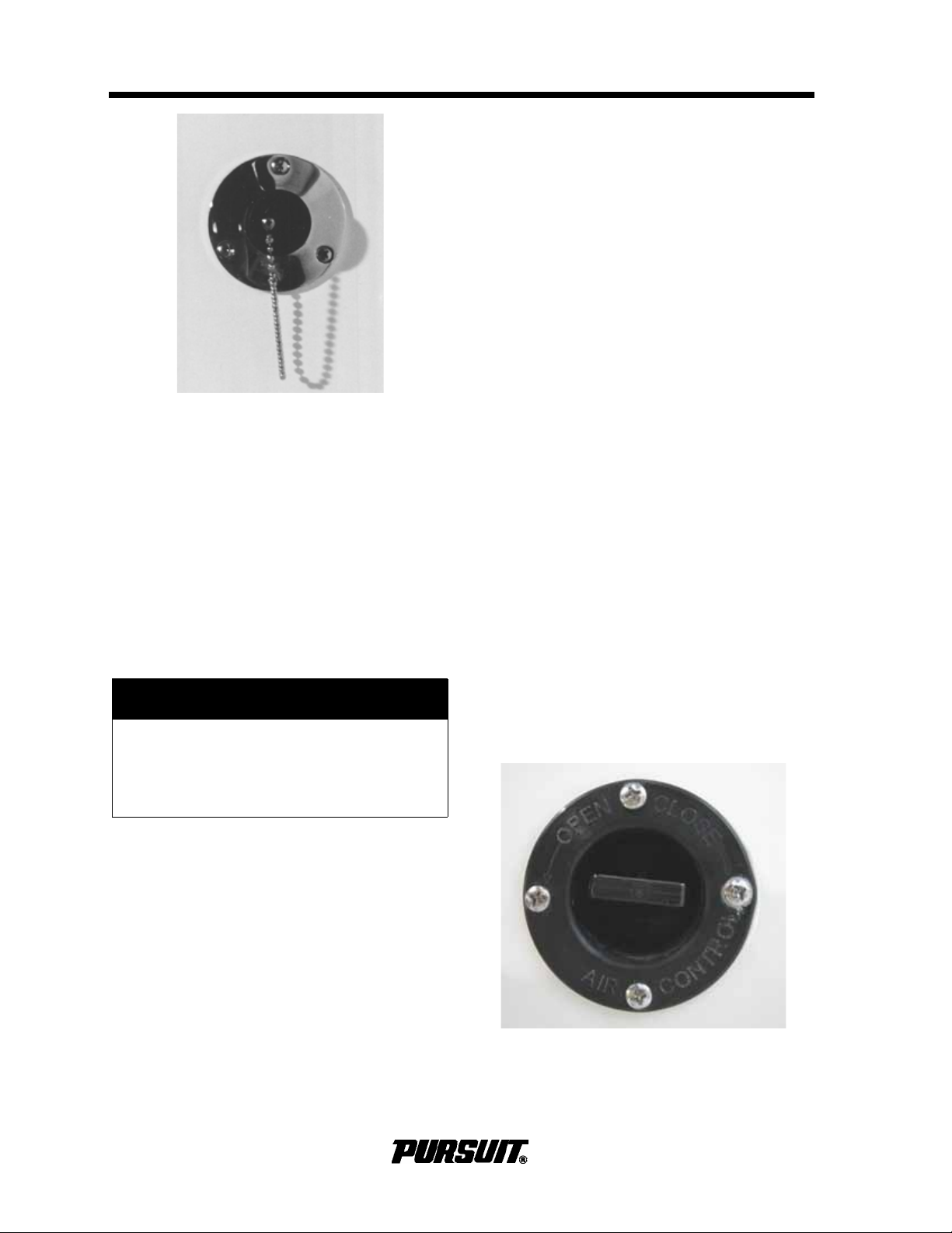
Section 5 Plumbing System
Aerator Valve (if equipped)
To fill the livewell, insert the plug into the
drain fitting at the bottom of the livewell.
Make sure the ball valve at the intake thruhull fitting is open and turn on livewell pump.
When water level reaches the overflow , it will
begin to circulate.
To drain, turn off pump and remove plug.
When the livewell has drained, use the
washdown hose to flush livewell and drain
debris.
Close the livewell thru-hull ball valve whenever livewell is not in use to prevent water
from entering the livewell while the boat is
cruising. The livewell pump on center con-
Washdown Hose Connector (Typical)
Priming the System
sole models is equipped with a sea strainer
on the intake side of the pump located in the
aft bilge. Check it frequently and clean as
necessary.
Open the ball valve and hose connector, and
activate the pressure pump. Run the pump
until all air is purged from the system. Close
the thru-hull ball valve before the boat is
hauled from the water to eliminate an air
lock in the system. It may be necessary to
re-prime the raw water system if the system
is not used for an extended period.
! CAUTION
DO NOT operate high-pressure pump
dry, damage to pump will result. Turn
the raw water pump switch "OFF"
when leaving the boat unattended.
5.3 Livewell
The livewell is standard on the C 280, C 310
and ST 310. The C 310 livewell is equipped
with an aerator.
Do not use livewell for stowage. Seawater
can enter livewell when it is not in use and
damage stowed equipment.
The livewell may be equipped with an aerator pump. The pump re-circulates the water
in the livewell. The livewell pump must be
operating, or the livewell full of water, with
the drain plug in place for the aerator pump
to function. The amount of aeration provided
by the pump, is controlled by a valve,
located on the forward side of the leaning
post.
Seawater is provided to the livewell by a 12volt circulating pump. This pump is designed
to carry a constant flow of water to the
livewell. The pump is activated by the
livewell switch on the helm. An overflow built
into the livewell automatically controls
livewell water level. Always turn livewell
pump off at the switch panel when not in
use.
5-2
C280 / S280 / C310 / ST310
Page 55
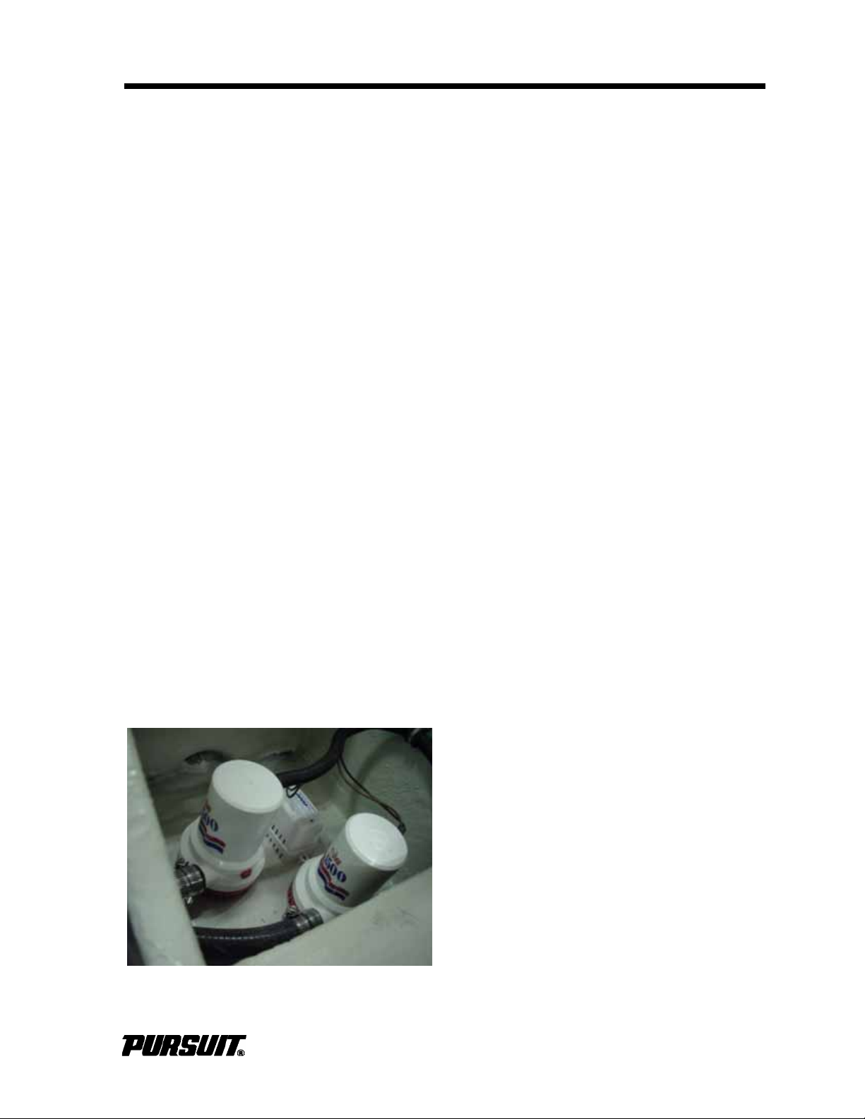
Plumbing System
Bilge Pump (Typical)
Section 5
5.4 Drainage
General
Some drain thru-hull fittings are equipped
with ball valves that are always open under
normal operating conditions. In the event of
an emergency, close the valves to prevent
sea water from entering the boat through the
drainage system. Check and operate the
drain valves at least once a month to make
sure they are in good condition and operating properly. Also, check the drain system to
ensure it is free flowing and hoses on the
thru-hull fittings are secure and not leaking.
Review and become familiar with the drainage schematic and location of the thru-hull
drain valves.
A situation requiring one or more drain
valves to be closed can be dangerous to
boat and all onboard. If this occurs, distribute PFD’s and take all necessary safety precautions, including notifying the Coast
Guard or local agency, until the problem is
determined and corrected.
Bilge Drainage
The bilge pumps are located in the stern
bilge. All bilge pumps pump water out of
thru-hulls located above the waterline in the
hull. See Electrical Systems for additional
information on bilge pump operation.
The aft bilge pump system consists of two
pumps and an automatic float switch. The
float switch activates one pump that is fully
automatic. The other pump is the manual
pump and is controlled by the switch at the
helm.
Current is supplied to the automatic float
switches whenever the batteries are connected. The bilge pump switches in the helm
are supplied current when the house battery
switch is in the "ON" position. The breaker
for the manual pump is on the helm switch
panel and the breaker for the automatic
function is located on the MDP.
ST 310 only
The bilge pump system on the ST310 has
been specifically designed for boats under
tow. The automatic operates as previously
described. The manual pump is connected
to a high bilge water alarm and operates
from the starboard engine battery. Should
the house battery become discharged and/
or the water level in the bilge activate the
high water alarm the manual bilge pump will
be activated and the boat's horn will sound.
Activate the manual bilge pump briefly each
time the boat is used to ensure pumps are
operating properly. Activate the automatic
switch manually to verify operation.
Inspect the bilge area frequently for evidence of excessive water. Continuous operation of the bilge pump can mean there is
excess water in the bilge. Debris can also
prevent the pump from operating or make it
operate continuously. Make sure no debris is
blocking the bilge pump float.
Bilge pumps and bilge pumping systems are
not designed for damage control. Continuous operation of the bilge can mean a leak
or a drain plug is installed incorrectly; make
sure all drain plugs are installed.
Excess water in the bilge area will adversely
affect the handling and maneuverability of
the boat and can cause personal injury. DO
NOT allow the bilge pump to operate after all
the water has been cleared from the bilge
area. Damage to the pump will occur.
C280 / S280 / C310 / ST310
5-3
Page 56

Section 5 Plumbing System
A loose drain plug will allow sea water to
enter the bilge and cause the boat to sink.
Check the drain plug frequently to make
sure it is secure. When the boat is out of the
water, the bilge can be drained by a thru-hull
drain located in the transom, near the bottom of the hull.
Any oil spilled in the bilge must be thoroughly removed and properly disposed of
before operating the bilge pump. The discharge of oil from the bilge is illegal and subject to fine.
! NOTICE
The federal water pollution control act
prohibits the discharge of oil or oily
waste into or upon the navigable
waters of the United States or the
waters of the contiguous zone if such
discharge causes a film or sheen
upon, or a discoloration of the surface
of the water, or causes a sludge or
emulsion beneath the surface of the
water. Violators are subject to a penalty of $10,000.
The rope locker drains overboard through a
special drain fitting located in the hull side at
the bottom of the rope locker. Inspect the
drain frequently to remove any accumulated
debris.
5.5 Plumbing System Maintenance
Information supplied with water system components, by the equipment manufacturers, is
included with this manual. Refer to the information for additional operation and service
information.
Fresh Water System
! CAUTION
Turn the fresh water system switch
"OFF" when leaving the boat unattended or when the fresh water system is not in use.
Perform these routine maintenance procedures to maintain your fresh water system:
Exterior Drains
Your Pursuit boat has two scupper drains
located in the rear of the cockpit. The drain
rails for the fishboxes and the mechanical
space drain overboard by gravity.
The below floor fishboxes are equipped with
a macerator pump and supplied with drain
plugs. Removing the drain plugs in the fishboxes will allow the fishboxes to be pumped
overboard. Insert the drain plug in the fishbox that empties first to completely drain the
other box. The fishboxes should be flushed
out and cleaned after each use.
All exterior sinks and livewells, provided with
fresh or raw water, drain by gravity to overboard thru-hulls.
The console cooler and the storage compartments, located in the bow, drain overboard.
• Remove filter screens from faucet spouts
and eliminate any accumulation of
debris. A debris build-up can cause the
pump to cycle excessively.
• Check and clean the fresh water system
strainer located on the intake line near
the pump at least annually.
• Remove the lid on the shower sump
assembly located under the mid-berth,
clean debris from the sump and flush
with clean water, activate the float switch
to test the pump and spray the pumps
and metal components with a metal protector periodically.
! CAUTION
Maintain a proper charge on the batteries, operating the pressure pump
from a battery with a low charge could
lead to pump failure.
5-4
C280 / S280 / C310 / ST310
Page 57

Plumbing System
Section 5
• Add a commercially available potable
water conditioner to the water tank to
keep it fresh.
• Make sure the fresh water system switch
is "OFF" when leaving the boat unattended or when not in use.
Raw Water System
! CAUTION
If a hose ruptures, turn pump off
immediately. Close the thru-hull valve
before performing maintenance on
sea water pump. Operating any pump
from a low-charged battery can lead to
a pump failure. Keep the batteries
properly charged. The raw water system must be properly winterized prior
to winter lay-up. Refer to Winterizing.
Perform these routine maintenance procedures to maintain your raw water system:
• Check hoses for signs of deterioration,
especially the sea water hoses.
• Remove and clean livewell, air conditioner and washdown pump sea water
strainers, as needed. Spray pumps and
thru-hull valves with a metal protector
periodically.
• Drain and clean the fishboxes and
livewells after each use.
• Operate all thru-hull valves at least once
a month to keep them operating properly.
If a hose ruptures or leaks, turn off pump
immediately. Keep the thru-hull valve closed
when performing service on a sea water system.
The fresh and raw water systems must be
winterized properly before storage. Refer to
Winterizing.
Drainage Systems
Perform these routine maintenance procedures to maintain your drainage system:
• Clean the cockpit drain rails with a hose
and water to remove all debris.
• Clean the hardtop leg drain holes, especially before winter storage.
• Clean the bilge pump and automatic float
switch strainers of any debris. Check the
bilge for debris that can block the function of automatic switch.
• Test rear automatic bilge pump switch
each time the boat is used, for proper
operation. Operate the knob or lever on
the side of the switch until the pump is
activated, or add water to the bilge until
the water level is high enough to activate
the pump.
• Flush all gravity drains with fresh water
to keep them clean and free flowing.
• Clean and inspect the shower and sink
drain sump system. Remove accumulated debris and flush with fresh water.
Test the automatic sump pump switch for
proper operation, frequently.
• Clean and flush the fishbox and cooler/
storage boxes with a mild soap or a bilge
cleaner and fresh water after each use to
keep them clean and fresh.
• Operate the thru-hull valves once a
month and service as required.
• Check the drain system regularly to
ensure it is free flowing and hoses on the
thru-hull fittings are secure and not leaking.
! CAUTION
Maintain a proper charge on the batteries; operating the pressure pump
from a battery with a low charge could
lead to pump failure.
C280 / S280 / C310 / ST310
! CAUTION
DO NOT use harsh chemical drain
cleaners in drain systems; permanent
damage to the hoses, fittings and system can result. Also, drains and
pumps must be properly winterized
before winter lay-up.
5-5
Page 58

Operator Notes
5-6
C280 / S280 / C310 / ST310
Page 59

Ventilation System
Section 6
Ventilation System
6.1 Head Compartment Ventilation
Ventilation is supplied by an opening port
lite.
Port Lites
The port lites are secured by adjustable
dogs. The dogs should be adjusted so they
are tight enough to seal the window in the
closed position, but not so tight that they are
difficult to latch. The dogs are adjusted by
turning a screw. The screw increases or
decreases the pressure on each dog. The
screen must be removed prior to closing the
port light to ensure a water resistant seal
except on the ST310 where is fixed in place.
6.2 Carbon Monoxide and Proper Ventilation
6.4 Maintenance
• Periodically lubricate all hinges and latch
assemblies with a light oil. And, clean
and coat gasket materials with silicone to
help keep them pliable.
• The opening cabin deck hatches and
port windows are made of acrylic plastic.
Acrylic can scratch easily. DO NOT use
a dry cloth or glass cleaning solutions;
use a soft cloth, mild soap, and water for
routine cleaning. Solvents and products
containing ammonia can permanently
damage acrylic. Refer to Routine Maintenance for more information on the
proper maintenance for acrylic.
Read "Carbon Monoxide" in the Safety Section. It contains important information on carbon monoxide and the carbon monoxide
detector.
6.3 Bilge Compartment Ventilation
Air flow into the bilge compartment is supplied by four vents on either side of the cockpit, under the gunwale boards.
C280 / S280 / C310 / ST310
6-1
Page 60

Operator Notes
6-2
C280 / S280 / C310 / ST310
Page 61
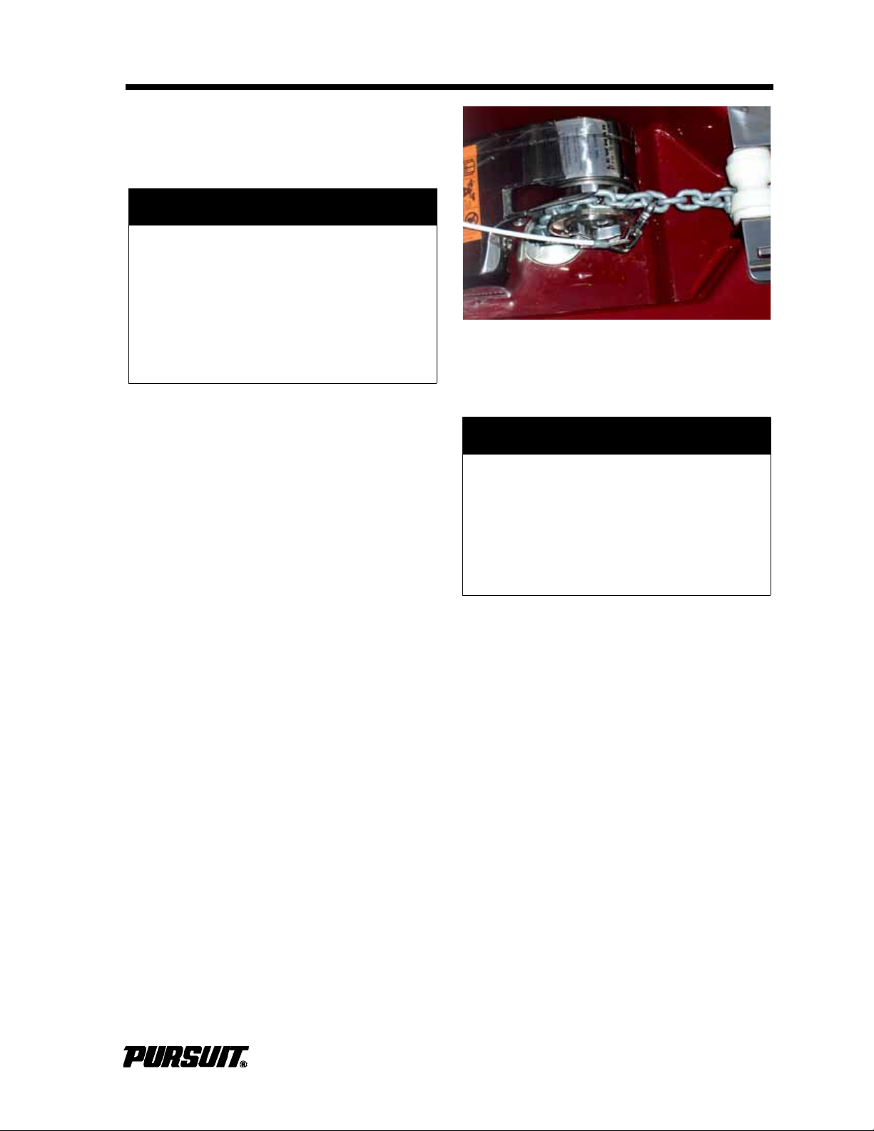
Exterior Equipment
Anchor Chain Secured
Exterior Equipment
7.1 Deck
! CAUTION
Unsecured open exterior doors and/or
hatches can slam closed and cause
injury or damage the boat. Most doors
and hatches are equipped with fasteners, hatch lifters, snaps and/or straps
to secure them open make sure they
are properly secured while they are
open.
Rails and Deck Hardware
Rails and deck hardware perform specific
functions. Do not use for securing fenders or
mooring lines; these must be secured to the
cleats. Make sure mooring lines are clear of
rails or stanchion, or damage can result.
Some cleats are flush mount and must be
raised prior to use.
Section 7
Secure anchor chain when trailering or while
underway.
! CAUTION
Secure anchor when it is stored in its
locker and make sure it does not rest
against the hull sides. If the anchor is
loose, it will bounce and damage the
boat. Damage from anchor bouncing
in the locker is not covered by the
Pursuit warranty.
DO NOT use cleats or any other hardware
for the purpose of towing or being towed.
Inspect all hardware periodically for loosening, wear or damage. Repair or replace
immediately.
Anchor/Rope Locker
The anchor locker at the bow of the boat can
be accessed through the deck hatch. A
bracket is provided to secure a Danforth®
type anchor.
The anchor locker is drained by a thru-hull
fitting in the hull side near the bottom of the
locker. Check it frequently and keep it clean
and free flowing.
Windlass (Optional)
The windlass is standard on the C 310 and S
310 and optional on the C 280 and S 280.
The windlass is located under the forward
deck hatch above the rope locker. The
anchor line is stored in the rope locker and
routed out through the windlass to the
anchor chain.
Become familiar with the safe operation of
the windless before using it. Refer to the
windlass owner's manual for use of the
windlass and remote control.
C280 / S280 / C310 / ST310
7-1
Page 62
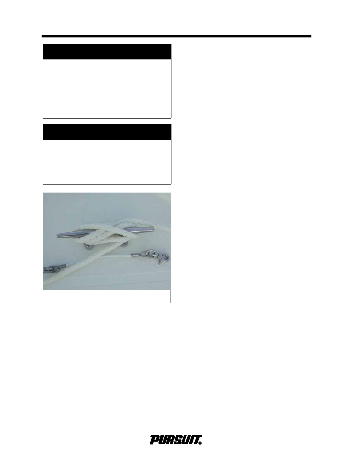
Section 7 Exterior Equipment
Anchor Line Secured to Cleat
! WARNING
MOVING PARTS OR
ENTANGLEMENT HAZARD
Contact with moving parts can entangle, cut, resulting in loss of body
parts, strangulation and/or severe
loss of blood, causing serious injury
or death. Stay clear of moving parts.
! CAUTION
DO NOT use windlass as the only
method of securing anchor in bow
pulpit. Secure anchor line to a cleat or
chain snubber before operating your
boat.
stowed correctly, plow/flukes down so the
anchor will not contact the hull. Once the
anchor is stowed, secure the anchor to the
chain snubber or bow cleat to prevent it from
being released while underway.
Boats at anchor in high swell conditions will
snub on the anchor line. This can cause slippage or apply excessive loads to the windlass.
DO NOT use the windlass as a winch to
move the boat over the anchor. Move the
boat under its own power to the anchor and
to break the anchor loose.
Downriggers (Dealer Installed)
Downriggers must be installed on the deck
area aft of the gunwale board. Your boat is
reinforced in this area for the installation of
downriggers. DO NOT install or insert downriggers in the rod holders mounted in the
gunwale boards; damage can occur.
The anchor is lowered by releasing the
anchor from the cleat or chain snubber on
the pulpit and activating the “Deploy” switch
at the helm. After the anchor is set, do not
allow the windlass to take the force from the
anchor line; secure line to the anchor line
cleat.
The anchor is retrieved by releasing the line
from the bow cleat and activating the
“Retrieve” switch at the helm. When the
chain begins to enter the windlass gypsy,
release the switch. Jog the switch to start
and stop the windlass, to allow the anchor to
properly seat for stowage in the anchor
roller. Inspect the anchor to ensure it is
7.2 Cockpit
Swim Platform
Your Pursuit boat is equipped with an integral swim platform. Inspection deck plates
are located in the splashwell to provide
access to the stern bilge and engine mounting bolts. On C280, S280 and C310 models
an access panel on the port side of the platform, provides access to the port rear bilge
and the port trim tab line. On the ST 310,
access to these component is through the
aft seat. Make sure these plates and
hatches are secure before operating your
boat. A self storing boarding ladder is
located under the hatch on the swim platform.
DO NOT use swim platform or ladder while
an engine is running. The engines must be
“OFF” before allowing anyone to enter or
exit the boat or when they are in the water.
Stow ladder before starting an engine.
7-2
C280 /S280 / C310 /ST310
Page 63

Exterior Equipment
Section 7
! DANGER
CARBON MONOXIDE POISONING
AND/OR ROTATING PARTS HAZARD
Poisonous CO gases are present at
the rear of the boat when an engine is
running. A rotating propeller can cut
or entangle swimmers. Both of these
hazards will cause death or serious
injury. DO NOT use the swim/boarding
platform when the engine is running.
Transom Door
Do not use the transom door when the boat
is in motion. DO NOT leave the transom
door unlatched. Latch it in the full “OPEN” or
full “CLOSED” position.
! WARNING
UNSAFE BOAT HAZARD
Failure to close and secure transom
door/gate while underway can expose
passengers to rotating propellers,
throw them overboard or swamp the
boat which can cause death or serious injury. Close and secure door/
gate before getting underway.
The sink is equipped with a fresh water
Sprayer and drains overboard. The cooler is
insulated and drains overboard. When the
livewell option is selected, the cooler is
replaced with the livewell. The tackle locker
below the sink provides access to the stern
bilge area.
Below Deck Fishbox
The fishboxe(s) located in the cockpit are
drained by a macerator pump located in the
bilge. Pump out and clean the fishboxe(s)
after each use. Refer to Drainage Systems
for more information on the fishbox drainage.
Refrigerator (S 280 and S 310)
The leaning post is equipped with a DC
refrigerator. While operating on 12-volt
power without the engines running, the
refrigerator may drain the battery severely,
with extended use. When at dockside make
sure the battery charger is ON. Refer to the
refrigerator owner's manual for additional
operating and maintenance instructions. The
"Fridge" breaker in the MDP provides circuit
protection for the refrigerator. Refer to the
Electrical System Chapter.
Aft Seats
! CAUTION
Inspect transom door/gate fittings
periodically for wear, damage or loose
fit. Repair or replace before using your
boat.
Stern Bait and Tackle Rigging Station
(C 280 and C 310)
The sink is equipped with a fresh water
sprayer and drains overboard. The cooler is
insulated and drains overboard. The tackle
locker below the sink provides access to the
stern bilge area.
C280 / S280 / C310 / ST310
C280, S280, C310. To open the aft seat, lift
the bolster and carefully lower the cushion to
the full lowered position. To close, lift the bolster and carefully raise the cushion to the full
closed position.
Keep hands away from the seat mechanism when opening and closing.
ST310
The stern bench seat is hinged and opens to
access the removable cooler. The engines
must be tilted to the full "DOWN" position,
the transom door open, and the latches
released to open the bench seat. A hatch
lifter will hold seat in the open position and
prevents it from opening too far. Remove the
cooler to access the bilge. Refer to Drainage
in the Plumbing Systems section.
7-3
Page 64

Section 7 Exterior Equipment
Forward Table and Sunpad Filler
! WARNING
(Optional on the S 310)
Damage to the engine cowlings, stern
seat and transom door can occur if
the stern seat is not opened properly.
The engines must be tilted to the full
down position, the transom door
opened and the latches at the front of
the seat released before the bench
seat can be opened.
Bow Seating and Storage
There are three storage compartments
located in the bow. The port and starboard
compartments are equipped with cushions
and locks for secure storage. Secure all
cushions snaps before using the seats or
getting underway. Racks are provided to
secure three rods. Make sure the rods are
secured properly in the storage rack before
getting underway. The rod racks can be
folded out of the way to provide more room
for storage.
The third compartment is located in the
cockpit sole and provides access to the
water and holding tanks.
The forward table is provided with a protective cover and long and short supports.
Secure the forward hatch before using the
table. The long support places the table at a
comfortable seating height. The shorter support places the table at the correct height to
use the sunpad filler. To prevent damage to
the table's finish whenever the table is not in
use, place the cover over the table. To complete the sunpad area, place the sunpad
filler cushion on top of the table. stores in
the head compartment, the table supports
are stored in the bow floor storage compartment.
! CAUTION
PERSONAL INJURY OR DAMAGE TO
EQUIPMENT.
Lock the forward hatch in the fully
locked position to prevent personal
injury or damage to the table. To prevent injury to persons or damage to
the table, the forward hatch must be
secured in the fully locked position.
Casting Platform/Sun Lounge
(Optional on the S 280)
The casting platform/sun lounge is hinged at
the bow and locks onto the console cooler.
Secure the locks before using the casting
platform/sun lounge or before getting underway. The platform is equipped with gas
springs to support it in the "UP" position and
to allow access to the forward deck hatch.
Secure all cushion snaps before getting
underway or before using the sun lounge.
T o prevent injury to persons, do not allow
passengers to stand on the casting platform/sun lounge when the boat in underway.
! WARNING
Serious injury can result from sitting
on, leaning on the table. DO NOT sit or
lean on the table when it is in the
upper seating position.
T-TOP.
The fiberglass T-top frame is white powder
coated aluminum and is designed to accommodate radio antennas, radar antennas and
navigation lights. It is equipped with an overhead storage compartment for life jackets, an
enclosed storage compartment and overhead
red and white lights and can be
optional outriggers and/or rod holders.
equipped with
7-4
C280 /S280 / C310 /ST310
Page 65

Exterior Equipment
! CAUTION
Care should be exercised to prevent
damage to powder coated surfaces. if
the surface is scratched, chipped or
worn exposing the aluminum, it
should be resealed to prevent corrosion from forming. If corrosion is
allowed to form, it could cause the
powder coating to bubble and lift
away. Contact your dealer for repair
service.
Section 7
If you have an optional drop curtain, slide it
into the slide track on the back of the T-top
and attach it to the rear of the side curtains.
Snap the drop curtain to the deck and cockpit.
Cold weather can make the clear vinyl material on the curtains stiff and difficult to stretch
to the snaps. This can be particularly difficult
with new canvas that has been stored off the
boat. Lay the curtains in the sun for 30 minutes during the heat of the day to make
installation easier in cold weather.
The T-top is not designed to support the
additional weight of items like an instrument
locker or a life raft. Radar and electronics
antennas must be mounted to the top
between the front and rear legs. Do not
mount any antennas or equipment to the
brow area. The hardtop frame is not
designed to support the weight of accessories in this area and can be damaged. The
starboard rear leg provides the chase for
components mounted to the top.
The T-Top warranty will be voided if the top
is modified in any way or heavy accessories
are mounted to the top. Also, if items like
radar antennas, spotlights and other accessories are mounted in the wrong location,
the warranty can be voided. If you intend to
add equipment or make modifications to the
hardtop, contact Pursuit Customer Relations
to make sure the equipment you would like
to add or the intended modification will not
void the warranty on the top.
Hardtop Canvas
Because the aluminum frames vary slightly,
the side curtains and front curtain are custom made to each boat at the factory. Slide
the front and side curtains into the slide
tracks on top of the windshield wings. Start
the zippers, but DO NOT zip closed. Snap
the front curtain first, then the side curtains
to the deck and then the T-Top legs. The
side curtains will have to be stretched
slightly to pull out the wrinkles and reach the
snaps. Once the curtains are snapped in
place, close the zippers.
There is a hole drilled in one of the leg bases
to prevent water from being trapped within
the leg and provide wire routing for accessories. A smaller hole is drilled in the tubing at
the base of the other legs is to allow water to
drain only. Keep the hardtop leg drains
clean, especially before winter lay-up.
7.3 Tower (Dealer Installed)
Your boat could be equipped with a dealer
installed aluminum tower. Towers are normally equipped with full engine controls,
compass, engine alarms, restart buttons and
tachometers. This allows for complete operation of the boat from the tower.
! NOTICE
To prevent gel coat, gunwales or deck
damage, supporting extension to the
stringers may be required. Damage
resulting from installation of a tower is
not covered by the Pursuit Limited
Warranty. Also, equipping a boat with
a tower may require lower pitched
propellers to compensate for the wind
resistance and weight of the tower.
C280 / S280 / C310 / ST310
7-5
Page 66

Section 7 Exterior Equipment
7.4 Bow Towing Eye (Optional)
The boat may be equipped with a Bow Towing Eye. Use of this option will require the
use of a Pennant that is attached to the Towing eye with a clevis secured with a bolt and
nut. Attached to the Pennant will be a Hawser of the correct length to match sea conditions and towing speed. The Hawser is
attached to a Bridle that is attached to the
towing boat. This gear should be designed
and assembled by a professional who specializes in marine towing systems.
It is the captain's responsibility to properly
specify , install and maintain the towing gear
to prevent injury to the towing boat's occupants or damage to the towed boat, other
boats.
! WARNING
Towing or being under tow is a hazardous operation that places high
stress on the boats' hardware and tow
lines. Never stand directly in line of
the tow line. Failure of any of these
parts can cas ue serious injury or damage.
7-6
C280 /S280 / C310 /ST310
Page 67

Interior Equipment
Section 8
Interior Equipment
8.1 Head Compartment
The head compartment is in the center console. The optional AC breaker panel, and
the electronics access panel are located in
head compartment. There are bilge access
doors in the compartment. The areas
accessed through these doors are part of
the bilge and are not intended for storage.
Marine Head System
This system is provided as standard equipment. The water for flushing water is supplied by a thru-hull fitting, located through an
access door next to the sink, and a raw
water line. Before using, open the inlet valve
on the head and pump to wet the inside of
the bowl. After use, close the valve and
pump to discharge the waste to the holding
tank. An electric head is optional. The electric head is flushed by using the switch,
mounted next to the head.
The holding tank is under the deck, forward
of the console. To access; open the bow
floor storage hatch. When the tank is full it
must either be pumped out by an approved
waste dumping station through the waste
deck fitting or be pumped overboard with the
macerator discharge pump, following the
proper overboard dumping regulations.when
legal to do so.
To operate the macerator discharge pump,
open the discharge ball valve, located
behind the hatch above the step. Then activate the macerator switch, located on the
switch panel in the head. When the tank is
emptied, and release the switch.
Maintenance
Clean and inspect the head for leaks regularly. Periodically add chemical to the head
to help control odor and to chemically break
down the waste. Refer to the head owner’s
manual for additional operating and maintenance information.
! NOTICE
DO NOT operate the macerator dry;
damage to the pump can occur.
In some waters it is illegal to discharge waste overboard. Remove the
seacock handle or use another
method to prevent accidental discharge.
Holding Tank and Macerator Discharge
Pump
Waste is pumped into the holding tank
where it remains until it is pumped out at a
waste dumping station or the overboard
macerator discharge system.
! NOTICE
The head and macerator systems
must be winterized before winter layup; refer to Winterizing.
8.2 Audio and Video Systems
Stereo
The stereo is located inside the console
head compartment. An iPod®/MP3 USB
input jack is included with the stereo system.
An optional satellite radio system is available. The antenna is installed on the T-top.
The satellite receiver is located behind the
electronics access panel located on the aft
. Refer to the stereo owner's manual.
wall
C280 / S280 / C310 / ST310
8-1
Page 68

Operator Notes
8-2
C280 / S280 / C310 / ST310
Page 69

Safety Equipment
Section 9
Safety Equipment
9.1 General
Your boat and outboard engines have been
equipped with safety equipment designed to
enhance the safe operation of the boat and
to meet U.S. Coast Guard safety standards.
The Coast Guard or state, county, and
municipal law enforcement agencies require
certain additional accessory safety equipment on each boat. This equipment varies
according to length and type of boat and
type of propulsion. Most of the accessory
equipment required by the Coast Guard is
described in this Section. Some local laws
require additional equipment. It is important
to obtain “Federal Requirements And Safety
Tips for Recreational Boats,” published by
the Coast Guard, and copies of state and
local laws, to make sure you have the
required equipment for your boating area.
You should also read the book entitled
"Sportfish, Cruisers, Yachts - Owner's Manual" included with this manual.
If the alarms sounds:
• throttle the engines back to idle immediately.
• shift to neutral.
• monitor the engine gauges to determine
the cause of the problem.
• if necessary, shut off the engines and
investigate until the cause of the problem
is found.
• if the boat is equipped with water sensors in the fuel filters, make sure to
check them for excessive water.
9.3 Neutral Safety Switch
Every throttle/shift control system has a neutral safety switch. The switch allows the
engines to be started in NEUTRAL only. If
engines will not start, make sure controls are
in NEUTRAL. Control or cable adjustments
may be required to correct this condition
should it persist. See your Pursuit Dealer for
necessary control and cable adjustments.
Refer to the Helm Systems for more information on the neutral safety switch.
Your Pursuit boat could be equipped with
engine alarms and cabin monitoring equipment. These systems are designed to
increase your boating safety by alerting you
to potentially serious problems in the primary power systems, the engine compartment and the cabin. Alarm systems are not
intended to lessen or replace good maintenance and “Pre-Cruise System Check."
This Section also describes safety related
equipment that could be installed on your
boat. This equipment will vary depending on
the type of engines and other options
installed by you or your dealer.
9.2 Engine Alarms
Most outboards are equipped with an audible alarm system mounted in the helm area
that monitors selected critical engine systems. The alarm will sound if one of these
systems begins to fail. Refer to the engine
owner’s manual for information on the
alarms installed with your engines and additional operating and maintenance information.
9.4 Engine Stop Switch
Your Pursuit boat is equipped with an engine
stop switch, clip and lanyard. When the lanyard is pulled, it will shut off the engines.
! WARNING
LOSS OF CONTROL AND UNSAFE
BOAT HAZARD
An engine stop switch system that is
not used or does not function correctly can cause death or serious
injury. DO NOT operate the boat if the
stop switch system does not function
properly.
The stop switch will stop an engine whenever the lanyard is pulled far enough to disconnect the clip from the switch. Attach the
lanyard to the boat operator whenever an
engine is running, but be aware of loss of
engine power if the switch is activated.
C280 / S280 / C310 /ST310
9-1
Page 70

Section 9 Safety Equipment
If the operator is thrown from the seat, or
moves too far from the helm, the lanyard will
disconnect the clip from the switch, shutting
off the engine.
To attach a lanyard, connect the clip to the
emergency stop switch and the hook to a
strong piece of clothing on the operator,
such as a belt loop.
If the engines will not start, the clip may not
be inserted into the engine stop switch properly or the control is not in neutral. Make
sure the clip is properly attached to the
engine stop switch before attempting to start
the engine.
Always carry a spare stop switch clip and
lanyard and instruct at least one other person onboard the operation of the stop switch
and location of the spare.
9.5 Automatic Fire Extinguishing System (with Optional Generator)
cient time has elapsed for the fire to be
extinguished and a flashback is no longer
possible, find and fix the problem, then the
override switch on the control panel can be
moved to the "OVERRIDE" position and the
engines can be restarted. Refer to the Automatic Fire Extinguisher System in the Helm
Systems.
If the extinguisher system is activated, shut
down all engines immediately. Turn off all
electrical systems, powered ventilation and
extinguish all smoking materials. DO NOT
open the engine compartment hatch, this will
feed oxygen to the fire and a flashback can
occur. Allow the extinguishing agent to soak
the generator compartment for at least 15
minutes and wait for hot metals or fuels to
cool before inspecting for cause or damage.
Have an approved portable fire extinguisher
at hand and ready for use and DO NOT
breathe fumes or vapors caused by the fire.
It is extremely important that you read,
understand and know how this system
works, refer to the manufacturer’s literature.
! WARNING
FIRE/EXPLOSION HAZARD
The gas of the fire extinguisher system displaces oxygen to “smother”
the fire. DO NOT open the hatch. Oxygen can feed a fire and flashback can
occur which can cause death or serious injury. If the onboard fire system
discharges, wait at least 15 minutes
before opening engine hatch.
The generator is equipped with an automatic
fire extinguishing system. The extinguisher
has been chosen and located to provide sufficient coverage of the generator compartment. While the system helps ensure bilge
fire protection, it does not eliminate the U.S.
Coast Guard requirement for hand held fire
extinguishers.
The system is equipped with an engine shutdown circuit to automatically shut down the
generator. The red light on the fire extinguisher control panel will light and an alarm
will sound if this should occur. When suffi-
9.6 Carbon Monoxide Hazards
! DANGER
CARBON MONOXIDE HAZARD
Exposure to CO will cause death or
serious injury. CO is colorless, odorless and extremely dangerous. Avoid
CO exposure and make sure the CO
detector is working properly.
Carbon monoxide (CO) poisoning is lethal
and should not be confused with seasickness, intoxication or heat exhaustion. If
someone complains of irritated eyes, headache, nausea, weakness or dizziness, or
you suspect carbon monoxide poisoning,
immediately move the person to fresh air,
investigate the cause, and take corrective
action. Seek medical attention if necessary.
All engines and fuel burning appliances produce CO as exhaust. Direct and prolonged
exposure to CO will cause BRAIN DAMAGE
or DEATH.
9-2
C280 / S280 / C310 /ST310
Page 71

Safety Equipment
Section 9
Other symptoms that may signal exposure
to CO: dizziness, flushed face, ears ringing,
headaches, tightness of chest or hyperventilation, drowsiness, fatigue or weakness,
inattention or confusion, lack of normal coordination, nausea and unconsciousness. The
victim’s skin also may turn red. A slight
buildup of CO in the human body over several hours causes headache, nausea and
other symptoms similar to food poisoning,
motion sickness or the flu. Anyone with
these symptoms should immediately be
moved to an area of fresh air. Have the victim breath deeply and seek immediate medical attention. To learn more about CO
poisoning, contact your local health authorities.
Carbon Monoxide Detector
If the carbon monoxide detector is activated,
this indicates the presence of CO, which can
be fatal. Evacuate the cabin immediately.
Make sure all passengers are accounted for.
DO NOT enter the cabin until you know it is
safe and the problem found and corrected.
CO detectors warn occupants of dangerous
accumulation of CO gas. It is automatically
activated whenever the house battery switch
panel feed breaker is "ON." When powered,
the green indicator will flash for ten to fifteen
minutes, indicating the unit is in its warm-up
stage. The green power indicator will stop
flashing when the sensor has reached optimum operating temperature. The indicator
will then switch from flashing green to solid
green, indicating the detector is activate.
Make sure the battery switch is on and the
power light is lit whenever the cabin is occupied.
This device uses a micro controller to continuously measure and accumulate CO levels.
Should a very high level of CO exist, the
alarm will sound within a few minutes. If
small quantities are present or high levels
are short-lived, the detector will accumulate
the information and determine when an
alarm level has been reached.
While a CO detector enhances your protection from CO poisoning, it does not guaran-
tee it will not occur. Do not use CO detectors
as a replacement for ordinary precautions or
periodic inspections of equipment. Never
rely on alarm systems to save lives; common sense is still the best form of protection.
Remember, the boat operator carries the
ultimate responsibility to make sure the boat
is properly ventilated and passengers are
not exposed to dangerous levels of CO. Be
alert to the symptoms and early warning
signs of carbon monoxide.
CO detectors are very reliable and rarely
sound false alarms. If the alarm sounds, DO
NOT think it is false. If anyone has been
exposed to CO, move them into fresh air
immediately. Never disable the CO detector
because you think the alarm may be false.
Carbon Monoxide Poisoning
Carbon monoxide (CO) is a by-product of
combustion, is invisible, tasteless, odorless
and is produced by all engines and most
heating and cooking appliances. It exists
wherever fuels are burned to generate
power or heat. The most common sources of
CO on boats are combustion engines, auxiliary generators and propane or butane
stoves.
These produce large amounts of CO and
should never be operated while sleeping.
High concentrations of CO can be fatal
within minutes. Many cases of CO poisoning
indicate that while victims are aware they
are not well, they become so disoriented
they are unable to save themselves by either
exiting the area or calling for help. Also,
young children, elderly persons and pets
may be the first affected. Drug or alcohol use
increases the effect of CO exposure. Individuals with cardiac or respiratory conditions
are very susceptible to the dangers of CO.
CO poisoning is especially dangerous during
sleep while victims are unaware of any side
effects.
Low levels of CO over an extended period of
time can be just as lethal as high doses over
a short period. Therefore, low levels of CO
can cause the alarm to sound before persons notice any symptoms.
C280 / S280 / C310 /ST310
9-3
Page 72
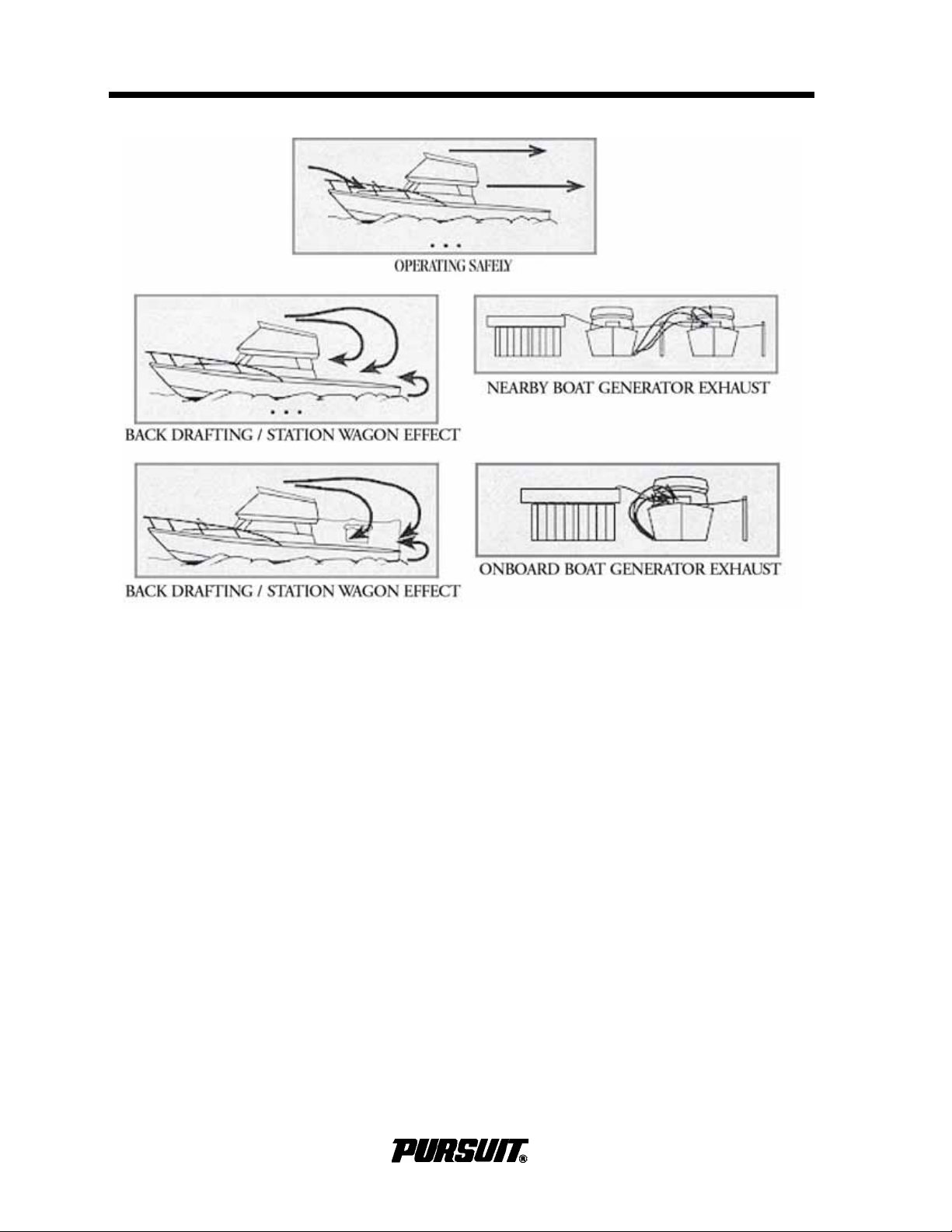
Section 9 Safety Equipment
Contact the detector manufacturer, the Pursuit Customer Relations Department or your
local fire department for assistance in finding
and correcting the situation.
In certain situations, boats can have a problem due to the “station wagon effect” where
engine exhaust fumes are captured in the
vessel by the vacuum or low pressure area,
usually the cockpit, bridge deck and cabin,
that can be created by the forward speed of
the boat. Boats that are underway should
close all aft facing portholes, hatches and
doors. The forward facing deck hatches
should be open whenever possible to help
pressurize living spaces of the boat. Sleeping, particularly in aft cabins, should not be
permitted while underway. Proper ventilation
must be maintained on the bridge deck by
opening a forward window or windshield to
drive fumes away from the occupants. The
canvas drop or aft curtain must be removed
and side curtains should be opened or
removed to increase airflow and maintain
proper ventilation whenever the engines are
running.
DO NOT operate the engines with side curtains closed and the aft or drop curtain
installed.
Use extreme caution while anchored or in a
slip and an auxiliary power generator is
operating. Calm wind nights can easily allow
fumes to enter the boat. Inspect the exhaust
systems of propulsion and the auxiliary generators, if equipped, frequently for possible
leaks. High concentrations of CO in your
boat can originate from an adjacent boat
through open hatches or windows.
Failure to properly ventilate the boat while
the engines are running can cause CO to
accumulate within the cabin. Make sure to
ventilate the boat and to avoid CO from
accumulating in the boat whenever an
engine is running.
9-4 C280 / S280 / C310 /ST310
Page 73
Safety Equipment
Section 9
Read the book entitled, "Sportfish, Cruisers,
Yachts - Owner's Manual" and the owner's
manual supplied by the CO detector manufacturer for additional information regarding
the hazards and symptoms of CO gas, CO
poisoning and operation instructions. If you
did not receive these manuals, contact the
Pursuit Customer Relations Department.
Many manufacturers of carbon monoxide
detectors offer a testing and recertification
program. We recommend that you contact
the manufacturer of your CO detector and
have it tested and recertified periodically.
Certain electronic equipment have a limited
life span, follow the CO detectors manufacturers recommendations on when the detector must be replaced.
9.7 First Aid
It is the boat operator's responsibility to be
familiar with proper first-aid procedures and
be able to care for minor injuries or illnesses
of your passengers. In an emergency, you
could be far from professional medical assistance, so be prepared. We recommend you
be prepared by receiving training in basic
first aid and CPR, through classes given by
the Red Cross or your local hospital.
Ask a medical professional about the supplies you should carry and the safe shelf life
of prescription drugs or other medical supplies you carry. Replace old supplies
whether they have been used or not.
In many emergency situations, the Coast
Guard can provide assistance in obtaining
medical advice for treatment of serious injuries or illness. If you are within VHF range of
a Coast Guard Station, make the initial contact on channel 16 and follow their instructions.
9.8 Required Safety Equipment
In addition to items installed by Pursuit, certain other equipment is required by the U.S.
Coast Guard to help ensure passenger
safety. Items like a sea anchor, working
anchor, extra dock lines, flare pistol, life
vests, a line permanently secured to your
ring buoy, etc., could at some time save your
passengers’ lives, or save your boat from
damage. Refer to the “Federal Requirements and Safety Tips for Recreational
Boats” pamphlet for a more detailed description of the required equipment. You can also
contact the U.S. Coast Guard Boating
Safety Hot line, 800-368-5647, for information on boat safety courses and brochures
listing the Federal equipment requirements.
Also, check your local and state regulations.
Equip your boat with at least a simple
marine first-aid kit and a first-aid manual.
The marine first-aid kit should be designed
for the marine environment and be well supplied. Keep it accessible so each person
onboard knows where it is located. As supplies are used, replace them. Some common drugs and antiseptics can lose their
strength or become unstable as they age.
C280 / S280 / C310 /ST310
The Coast Guard Auxiliary offers a “Courtesy Examination.” This inspection will help
ensure your boat is equipped with all of the
necessary safety equipment.
The following is a list of the accessory equipment required on your boat by the U.S.
Coast Guard:
Personal Flotation Devices (PFD's)
PFD's must be Coast Guard approved, in
good and serviceable condition, and of
appropriate size for the intended user . We arable PFD's must be readily accessible,
meaning you must be able to put them on in
a reasonable amount of time in an emergency. Though not required, the Coast
Guard emphasizes that PFD's should be
9-5
Page 74

Section 9 Safety Equipment
worn at all times when the vessel is underway. Throwable devices must be immediately available for use. All Pursuit boats
must be equipped with at least one Type I, II
or III PFD for each person onboard, plus one
throwable device (Type IV).
Visual Distress Signals
All Pursuit boats used on coastal waters, the
Great Lakes, territorial seas, and those
waters connected directly to them, must be
equipped with Coast Guard approved visual
distress signals. These signals are either
Pyrotechnic or Non-Pyrotechnic devices.
Pyrotechnic Visual Distress Signals
Pyrotechnic visual distress signals must be
Coast Guard approved, in serviceable condition and readily accessible. They are
marked with a date showing the service life,
which must not have expired. A minimum of
three are required. Some pyrotechnic signals meet both day and night use requirements. They should be stored in a cool, dry
location. They include;
• pyrotechnic red flares, hand held or aerial.
• pyrotechnic orange smoke, hand-held or
floating.
• launchers for aerial red meteors or parachute flares.
Pyrotechnics are universally recognized as
excellent distress signals. However, there is
potential for injury and property damage if
not handled properly. These devices produce a very hot flame and the residue can
cause burns and ignite flammable material.
Pistol launched and hand-held parachute
flares and meteors have many characteristics of a firearm and must be handled with
caution. In some states they are considered
a firearm and prohibited from use. Make
sure you are careful and follow the manufacturer's instructions when using pyrotechnic
distress signals.
Pyrotechnic signaling devices can
cause fire and/or explosion, death,
serious injury and property damage if
misused. Follow the manufacturer’s
directions in the use of these signaling devices.
Non-Pyrotechnic Devices
Non-Pyrotechnic visual distress signals
must be in serviceable condition, readily
accessible, and certified by the manufacturer as complying with U.S. Coast Guard
requirements. They include:
Orange Distress Flag, day use only.
The distress flag is a day signal only. It must
be at least 3 x 3 feet with a black square and
ball on an orange background. It is most distinctive when attached and waved from a
paddle or boat hook.
Electric Distress Light, night use only.
The electric distress light is accepted for
night use only and must automatically flash
the international SOS distress signal. Under
Inland Navigation Rules, a high intensity
white light flashing at regular intervals from
50-70 times per minute is considered a distress signal.
Sound Signaling Devices
The navigation rules require sound signals
to be made under certain circumstances.
Recreational vessels are also required to
sound fog signals during periods of reduced
visibility. Therefore, you must have some
means of making an efficient sound signal.
Navigation Lights
Recreational boats are required to display
navigation lights between sunset and sunrise and other periods of reduced visibility
(fog, rain, haze, etc.) Navigation lights are
intended to keep other vessels informed of
! WARNING
FIRE/EXPLOSION HAZARD
9-6
C280 / S280 / C310 /ST310
Page 75

Safety Equipment
Section 9
your presence and course. Your Pursuit boat
is equipped with the navigation lights
required by the U.S. Coast Guard at the time
of manufacture. It is up to you to make sure
they are visible, operational and turned on
when required.
Fire Extinguishers
Pursuit Boats provides locations for two fire
extinguishers on boats under 26 feet. Boats
over 26 feet have provisions for up to three
fire extinguishers. Boats equipped with cabins have one fire extinguisher located in the
cabin, cockpit and helm areas. Center console boats have fire extinguishers mounted
in the vicinity of the helm and passenger
cockpit. Coast Guard approved fire extinguishers are hand-portable, either B-I or B-II
classification and have a specific marine
type mounting bracket. It is recommended
the extinguishers be mounted in a readily
accessible position.
Fire extinguishers require regular inspections to ensure:
Bilge And Fuel Fires
Fuel compartment and bilge fires or explosions are dangerous because of the presence of fuel. You must make the decision to
fight the fire or abandon the boat. If the fire
cannot be extinguished quickly or it is too
intense to fight, abandoning the boat may be
your only option. You must consider your
safety, the safety of your passengers, the
intensity of the fire and the possibility of an
explosion in your decision.
If you find yourself in this situation, make
sure all passengers have a life preserver on
and go over the side and swim well upwind
of the boat, to keep clear of any burning fuel
that could be released and spread on the
water as the boat burns or in the event of an
explosion. When clear of the danger, check
and account for all passengers who were
onboard. Give whatever assistance you can
to anyone in need or in the water without a
buoyant device. Keep everyone together for
morale and to aid rescue operations.
• seals and tamper indicators are not bro-
ken or missing.
• pressure gauges or indicators read in the
operable range.
• no obvious physical damage, corrosion,
leakage or clogged nozzles.
For information on the type and size fire
extinguisher required for your boat, refer to
the “Federal Requirements and Safety Tips
for Recreational Boats” pamphlet or contact
the U.S. Coast Guard Boating Safety Hot
line, 1-800-368-5647.
For instructions on the proper maintenance
and use of your fire extinguisher, refer to the
information provided by the fire extinguisher
manufacturer.
Information for halon or agent FE-241 extinguishers is provided by the manufacturer. It
is extremely important that you read, understand and know how this system works;
refer to the manufacturer’s literature.
! WARNING
BURN HAZARD
Fuel floating on water which is ignited
can cause death or serious injury.
Fuel will float on top of water and can
burn. If the boat is abandoned, swim
upwind, far enough to avoid fuel that
can spread over the surface of the
water.
C280 / S280 / C310 /ST310
9-7
Page 76

Section 9 Safety Equipment
9.9 Additional Safety Equipment
Besides meeting the legal requirements,
prudent boaters carry additional safety
equipment. This is particularly important if
you operate your boat offshore. You should
consider the following items, depending on
how you use your boat.
Satellite EPIRB 'S
EPIRB's (Emergency Position Indicating
Radio Beacon) operate as part of a world
wide distress system. When activated,
EPIRB's will send distress code homing beacons that allow Coast Guard aircraft to identify and find them quickly. The satellites that
receive and relay EPIRB signals are operated by the National Oceanic and Atmospheric Administration (NOAA) in the United
States. The EPIRB should be mounted and
registered according to the instructions provided with the beacon, so the beacon's
unique distress code can be used to quickly
identify the boat and owner.
Additional Equipment to Consider:
❑ VHF Radio
❑ Life Raft
❑ Spare Anchor
❑ Spare Keys
❑ Heaving Line
❑ Fenders
❑ First Aid Kit
❑ Portable Radio
❑ Flashlight and Batteries
❑ Mirror
❑ Searchlight
❑ Sunburn Lotion
❑ Tool Kit
❑ Ring Buoy
❑ Whistle or Horn
❑ Anchor
❑ Chart and Compass
❑ Boat Hook
❑ Spare Propellers
❑ Mooring Lines
❑ Food and Water
❑ Binoculars
❑ Sunglasses
❑ Marine Hardware
❑ Extra Clothing
❑ Spare Parts
9-8
C280 / S280 / C310 /ST310
Page 77

Operation
Section 10
Operation
10.1 General
Before you start, become familiar with the
various component systems and their operation, and perform a “Pre-Cruise System
Check." A thorough understanding of the
component systems and their operation is
essential to operate the boat safely. This
manual and the associated manufacturers’
information have been provided to enhance
your knowledge of your boat. Read them
carefully, and also, read the book titled
"Sportfish, Cruisers, Yachts - Owner's Manual."
Your boat must have the necessary safety
equipment onboard and be in compliance
with the U.S. Coast Guard, local and state
safety regulations. There should be one Personal Floatation Device (PFD) for each person. Non-swimmers and small children
should wear PFD's at all times. You should
know and understand the “Rules of the
Road" and have had an experienced operator brief you on the general operation of your
new boat. At least one other person should
be instructed on the proper operation of the
boat in case the operator is suddenly incapacitated.
The operator is responsible for his safety
and the safety of his passengers. When
boarding or loading the boat, always step
onto the boat, never jump.
Passengers should be seated to properly
balance the load and must not obstruct the
operator's view, particularly to the front.
Overloading and improper distribution of
weight can cause the boat to become unstable and are significant causes of accidents.
Know the weight capacity and horsepower
rating of your boat. Do not overload or overpower your boat.
! WARNING
OVERLOAD HAZARD
Overloading the boat beyond maximum load or altering the stability,
buoyancy or center-of-gravity can
result in death or serious injury. DO
NOT exceed the maximum load or
alter the center-of-gravity of the boat.
Remember, it is the operator's responsibility
to use good common sense and sound judgment in loading and operating the boat.
! WARNING
SLIPPERY SURFACE HAZARD
Wet surfaces can generate slippery
conditions which can result in death
or serious injury. Use caution on wet
surfaces.
10.2 Homeland Security Restrictions
! WARNING
DROWNING OR LOSS OF
CONTROL HAZARD
Ejection or sudden loss of control can
cause death or serious injury from
improper use of seating. DO NOT
stand while driving above engine idle
speeds and make sure cockpit seat is
locked/secured and all passengers are
seated when boat is underway.
DO NOT allow passengers to sit on the seat
backs, gunwales, bows, transoms or on fishing seats whenever the boat is underway.
C280 / S280 / C310 / ST310
• Recreational boaters have a role in
keeping our waterways safe and secure.
Violators of the restrictions below can
expect a quick and severe response:
• Do not approach within 100 yards, and
slow to minimum speed within 500 yards
of any U.S. Naval vessel. If you need to
pass within 100 yards of a U.S. Naval
vessel, for safe passage you must contact the U.S. Naval vessel or the Coast
Guard escort vessel on VHF-FM channel
16.
• Observe and avoid all security zones.
Avoid commercial port areas, especially
those that involve military, cruise-line or
10-1
Page 78
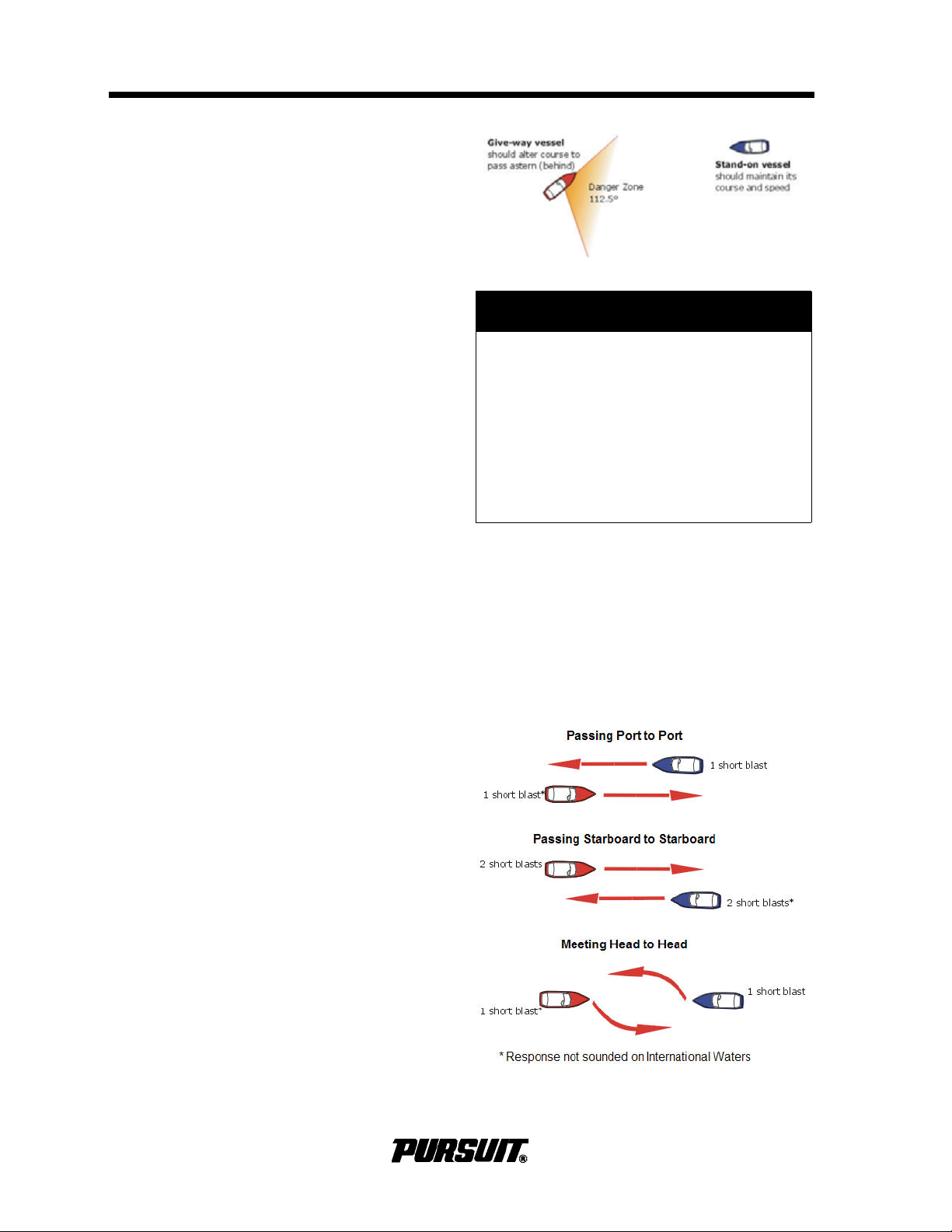
Section 10 Operation
petroleum facilities. Observe and avoid
other restricted areas near dams, power
plants, etc.
• Do not stop or anchor beneath bridges
or in channels.
America’s Waterway Watch
America's Waterway Watch, a combined
effort of the Coast Guard and its Reserve
and Auxiliary, wants your help in keeping
America's waterways safe and secure.
America's Waterway Watch urges you to
adopt a heightened sense of sensitivity
toward unusual events or individuals you
may encounter in or around ports, docks,
marinas, riversides, beaches or waterfront
communities. To report suspicious activities,
call the National Response Center at 1-87724WATCH or 1-800-424-8802. If there is
immediate danger to life or property call 911
or call the Coast Guard on Marine channel
16.
10.3 Rules of the Road
As in driving an automobile, there are a few
rules you must know for safe boating operation. The following information describes the
basic navigation rules and action to be taken
by vessels in a crossing, meeting or overtaking situation while operating in inland
waters. These are basic examples and not
intended to teach all the rules of navigation.
For further information consult the “Navigation Rules” or contact the Coast Guard,
Coast Guard Auxiliary, Department of Natural Resources, or your local boat club. These
organizations sponsor courses in boat handling, including rules of the road. We
strongly recommend such courses. Books
on this subject are also available from your
local library.
! CAUTION
Avoid collisions by following navigation rules. If a collision appears
unavoidable, both vessels must act.
Prudence takes precedence over
right-of-way rules if a crash is imminent. Less maneuverable boats generally have the right of way. Steer clear
of the right-of-way boat and pass to its
stern.
When two motor boats are crossing, the
boat on the right has the right of way and
should maintain its course and speed. The
other vessel should slow down and permit it
to pass. Both boats should sound appropriate signals.
Crossing situations
When two motor boats are crossing, the
boat on the right has the right of way and
should maintain its course and speed. The
other vessel should slow down and permit it
to pass. Both boats should sound appropriate signals.
10-2
C280 / S280 / C310 / ST310
Page 79
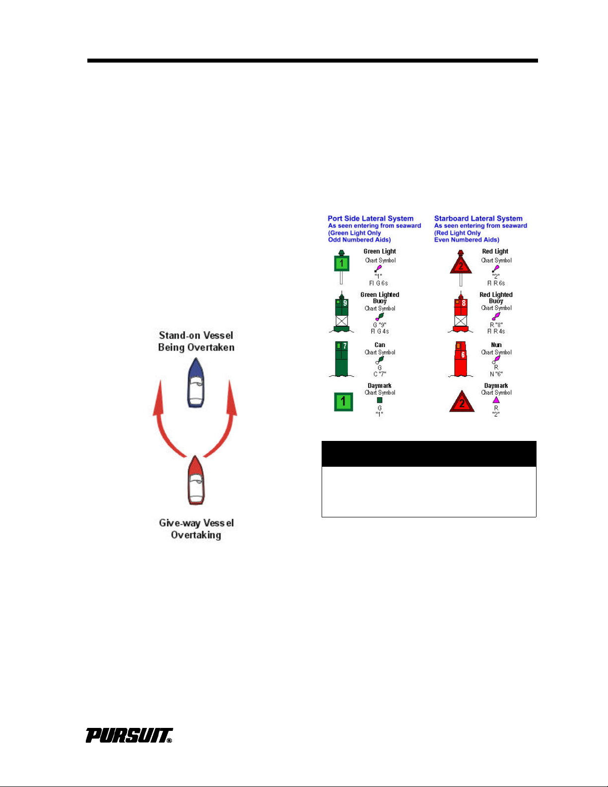
Operation
Section 10
Meeting Head-On Or Nearly-So
Situations
When two motorboats are approaching each
other head-on or nearly head-on, neither
boat has the right of way. Both boats should
reduce their speed and turn to the right,
passing port side to port side and provide
enough clearance for safe passage. Both
boats should sound appropriate signals.
Overtaking Situations
When one motorboat is overtaking another
motorboat, the boat being passed has the
right of way. The overtaking boat must make
adjustments necessary to provide clearance
for a safe passage of the other vessel and
should sound appropriate signals.
Navigation Aids
Aids to navigation are placed along coasts
and navigable waters as guides to mark safe
water and to assist mariners in determining
their position in relation to land and hidden
dangers. Each aid to navigation is used to
provide specific information. Become familiar with these and any other markers used in
your boating area.
The General Prudential Rule
In obeying the Rules of the Road, due
regard must be given to all dangers of navigation and collision and to any special circumstances, including the limitations of the
vessels, which may justify a departure from
the rules that is nec essary to avoid imm ediate danger or a collision.
! CAUTION
Storms and waves can move buoys,
do not rely on buoys alone to determine your position.
10.4 Pre-Cruise Check
Before Starting The Engines:
• Check the weather forecast. Decide if
your planned cruise can be made safely.
• Make sure all required documents are
onboard.
• Make sure all necessary safety equipment is onboard and operative; items
like running lights, spotlight, life saving
devices, etc. Refer to Safety Equipment
for additional information.
C280 / S280 / C310 / ST310
10-3
Page 80

Section 10 Operation
Each person onboard must have at least
one personal flotation device onboard and
one throwable device. Check the U.S. Coast
Guard standards for the correct type
required for your boat.
• Make sure signal kits are onboard and
are in good operating condition and are
not expired.
• Make sure you have sufficient water and
other provisions for the planned cruise.
• Leave a written message listing details
of your planned cruise (Float Plan) with a
close friend ashore. Include a description of your boat, where you intend to
cruise, schedule of your arrival in the
cruising area and when you expect to
return. Keep the person informed of any
changes in your plan to prevent false
alarms. This information can tell authorities where to look and your boat type in
the event you fail to arrive.
• Check the amount of fuel onboard.
Observe the “rule of thirds”: one third of
the fuel for the trip out, one third to return
and one third in reserve. An additional
15% may be consumed in rough seas.
• Check the water separating fuel filters for
water.
• Turn on the battery switches.
• Check for bilge water and for other signs
of potential problems. Monitor for the
scent of fuel fumes.
• Test the automatic and manual bilge
pump switches to make sure the system
is working properly.
• Have a tool kit and spare parts onboard.
The kit should include basic tools:
❑ Spark Plug Wrench
❑ Hammer
❑ Spark Plug Gap Gauge
❑ Electrician’s Tape
❑ Screwdrivers
❑ Lubricating Oil
❑ Pliers
❑ Jackknife
❑ Adjustable Wrench
❑ Vise Grip Pliers
❑ Needle Nose Pliers
❑ Wire Crimping Tool
❑ End Wrench Set
❑ Wire Connector Set
The spare parts kit should include:
❑ Extra Light Bulbs
❑ Spark Plugs
❑ Fuses and Circuit Breakers
❑ Flashlight and Batteries
❑ Drain Plugs
❑ Engine Oil
❑ Propellers
❑ Fuel Filters
❑ Propeller Nuts
❑ Fuel Hose and Clamps
• Make sure all fire extinguishers are in
position and in good operating condition.
• Make sure the shift control is in NEUTRAL.
• Make sure the emergency engine stop
lanyard is attached to the operator and
the stop switch.
10.5 Operating your Boat
The operator must be seated, and ready
with the controls (steering/throttle) when the
engine is started or running.
After Starting the Engines:
• Check engine gauges. Make sure all are
reading normally.
• Visibly check engines to be sure there
are no apparent water, fuel or oil leaks.
• Check operation of engine cooling systems.
• Check controls and steering for smooth
and proper operation.
• Allow engines to warm up for 10 to 15
minutes before operating them above
idle speeds.
• Make sure all lines, cables, anchors, etc.
for securing the boat are onboard and in
good condition. All lines should be
coiled, secured and off the decks when
underway.
• Have a safe cruise and enjoy yourself.
REMEMBER:
When operating a boat, you accept the
responsibility for the boat, safety of passengers and others out enjoying the water.
10-4
C280 / S280 / C310 / ST310
Page 81

Operation
Section 10
• Alcohol and any mind altering chemicals
can severely reduce your reaction time
and affect your better judgment.
• Alcohol reduces the ability to react.
• Alcohol makes it difficult to judge speed
and distance or track moving objects.
• Alcohol reduces night vision and ability
to distinguish red from green.
STAY ALERT. The use of alcohol or any
other mind altering chemicals that impair
judgment, pose a serious threat to you and
others. The boat operator is responsible for
their consequences and behavior of passengers.
! WARNING
IMPAIRED OPERATION HAZARD
Operating any boat while intoxicated
or under the influence of other drugs
can cause death or serious injury. DO
NOT operate any boat under the influence of any mind-altering chemical.
If the drive unit hits an underwater object,
stop the engine. Inspect drive unit for damage. If damaged contact your dealer for a
complete inspection and repair of the unit.
Stopping the Boat
• Allow engines to drop to the idle speed.
• Shift controls to NEUTRAL.
If the engines have been run at high speed
for a long period of time, allow engines to
cool by running at idle for 3 to 5 minutes.
• Turn the ignition keys "OFF."
• Raise the trim tabs to full “UP” position.
! CAUTION
Turn off engines at idle speed. Racing
the engine before switching it off can
draw water into the engine through
the exhaust, resulting in internal damage.
Avoid sea conditions that are beyond the
skill and experience of you and your crew.
Make sure at least one other person
onboard is instructed in the operation of the
boat and it is operated in compliance with all
state and local laws.
DO NOT operate the boat unless it is completely assembled. Make sure all fasteners
are tight and adjustments are to specifications.
Before operating the boat for the first time,
read the engine break-in procedures. Refer
to the engine owner’s manual. Since different types of engines are used, have your
dealer describe the operating procedures for
your boat. For more instructions on “How to
Operate the Boat,” read the instructions
given to you for your engines.
For more instructions on safety, equipment
and boat handling, enroll in one of the several free boating courses offered. For information on the courses offered in your area,
call the “Boating Safety Hot line,” 800-368-
5647.
After operation:
• If operated in saltwater, wash the boat
and all equipment with soap and water.
Flush the engines using fresh water.
Refer to the engine owner's manual for
instructions on flushing.
• Check the bilge area for debris and
excess water.
• Fill the fuel tanks to near full to reduce
condensation. Allow room in the tanks
for the fuel to expand without being
forced out the vent.
• Turn off all electrical equipment except
the automatic bilge pumps.
• If you are going to leave the boat unattended for a long period of time, put the
battery main switches to “OFF” and
close all seacocks.
• Make sure the boat is securely moored.
C280 / S280 / C310 / ST310
10-5
Page 82

Section 10 Operation
Safety precautions for tower operation:
! CAUTION
• Do not operate boat from tower in rough
To prevent damage, close all seacocks before leaving the boat.
10.6 Fishing
Fishing can be very exciting and distracting
for the operator of the boat when the action
gets intense. Be conscious that your primary
responsibility is operating the boat safely to
protect yourself, your passengers and other
boats around you. Make sure the helm is
properly manned and is never left unattended while trolling.
If you are fishing in an area that is crowded
with other fishing boats, it may be difficult to
follow the rules of the road. This situation
can become especially difficult when most
boats are trolling. Be courteous and exercise
good common sense. Avoid trying to assert
your right of way and stay clear to preventing tangled or cut lines and other unpleasant
encounters. Also, keep in mind that fishing
line wrapped around a propeller shaft can
cause damage to the lower unit seal.
10.7 Tower Operation (Dealer Installation)
Operation of the Tower Controls
Start engines at the lower helm. Monitor
gauges to make sure all systems are normal
and engines are warmed up before proceeding to the tower helm. The ignition or restart
switches on the tower are only used to
restart an engine in the event it should stall.
The shift controls must be in neutral for the
restart switches to be functional.
sea conditions. Motions of the boat are
exaggerated in the tower and may
become excessive in rough seas.
• Be careful when using the trim tabs from
the tower. The reaction of the trim tabs
will be exaggerated in the tower. Use
small tab corrections and wait ten (10)
seconds for the tabs to react. Keep making small corrections until the hull is at
the desired attitude.
• Do not overload the tower. Most towers
are designed for two average-sized people and weight in the tower affects the
center of gravity and motion of the boat
is greatly exaggerated for the people in a
tower, too much weight can make the
boat unstable.
• Do not operate the boat in tight quarters,
such as marinas, from the tower. The
operator is isolated from the boat while
in the tower and will not be able to assist
in docking procedures.
• Avoid using the tower in wet or rough
weather, your grip and footing on the
tower ladders is reduced.
• Operating the boat from the tower in
unfamiliar waters or where running
aground, can eject the operator or passengers.
• Be alert for waves and boat wakes; the
motion of the boat is exaggerated in the
tower.
• Exercise good common sense and judgment when operating a boat from the
tower.
• If the engine alarm sounds, put the boat
in NEUTRAL and shut "OFF" the engine
immediately until the problem is found.
• Always put the boat in NEUTRAL before
moving to and from the tower helm and
cockpit.
10-6
Use common sense, judgment and exercise
caution when operating the boat with someone in the tower. DO NOT allow anyone in
the tower when the water is rough or when
operating in unfamiliar waters where running
aground is a possibility. Remember, weight
in the tower affects center of gravity and
motion of the boat is greatly exaggerated for
people in the tower.
C280 / S280 / C310 / ST310
Page 83

Operation
Section 10
10.8 Docking, Anchoring and Mooring
Docking and Docklines
Maneuvering a boat near a dock and securing it requires skill and techniques that are
unique to water and wind conditions, and the
dock layout. If possible, position a crew
member at the bow and stern to assist with
the lines and docking. While maneuvering
close to the dock, compensate for wind and
current, and anticipate how you can use
them to help docking. Practice in open water
using an imaginary dock to develop a sense
for how the boat handles in different scenarios. You must be able to understand docking
techniques before problems occur.
Approaching a dock or backing into a slip in
high winds or strong currents requires skill. If
you are new to handling a boat, take lessons
from an experienced pilot and learn to
maneuver in tight quarters in less than ideal
conditions. Also, practice away from the
dock during windy conditions.
Dock lines are generally twisted or braided
nylon. Nylon is strong and stretches to
absorb shock. Nylon also has a long life and
is soft and easy on the hands. The size of
the line, will vary with the size of the boat.
Typically a 30 to 40 foot boat will use 5/8inch line and a 20 to 30 foot boat will use 1/
2-inch line. The number of lines and their
configuration will vary depending on the
dock, the range of the tide, and other factors. Usually a combination of bow, stern
and spring lines is used to secure the boat.
Maneuvering to the Dock
Approach the dock slowly at a 30 to 40
degree angle. When possible, approach
against the wind or current. Turn the engine s
straight and shift to neutral when you feel
you have enough momentum to reach the
dock. Use reverse to slow the boat and pull
the stern toward the dock as the boat
approaches. If you approached properly, the
boat will lightly touch the pilings at the same
time forward momentum is stopped. Have
the dock lines ready and secure the boat as
soon at it stops. Use fenders to protect the
boat while it is docked. Keep the engines
running until the lines are secured.
Backing into a Slip
Approach the slip with the stern against the
wind or current and the engines straight
ahead. Use the engines and turn the steering wheel to maneuver the boat into alignment with the slip. Reverse the engines and
slowly back into the slip. Shift from reverse
to neutral frequently at idle to prevent the
boat from gaining too much speed. Move the
stern right and left by shifting the engines in
and out of gear or turning the wheel. When
nearly in the slip all the way, straighten the
engines and shift to forward to stop. Keep
the engines running until the lines are
secured.
Securing Docklines
Securing a boat along side the dock typically
requires a bow and stern line and two spring
lines. The bow and stern lines are usually
secured to the dock at a 40 degree angle aft
of the stern cleat and forward of the bow
cleat. The after bow spring line is secured to
the dock at a 40 degree angle aft of the after
bow spring cleat. The forward quarter spring
is secured to the dock at a 40 degree angle
forward of the stern cleat. The spring lines
keep the boat square to the dock and reduce
fore and aft movement while allowing the
boat to move up and down with the tide.
Securing a boat in a slip is somewhat different. It typically requires two bow lines
secured to pilings on each side of the bow,
two stern lines secured to the dock and two
spring lines that prevent the boat from hitting
the dock. The bow lines are typically
secured with enough slack to allow the boat
to ride the tide. The stern lines are crossed.
One line runs from the port aft boat cleat to
the starboard dock cleat and the other line
runs from the starboard aft boat cleat to the
port cleat on the dock. The stern lines center
the boat, control the forward motion and
allow the boat to ride the tide. Two forward
quarter spring lines typically are secured to
the stern cleats and to mid ship pilings or
C280 / S280 / C310 / ST310
10-7
Page 84

Section 10 Operation
cleats. The spring lines keep the boat from
backing into the dock while allowing it to ride
the tide.
Leaving the Dock
Start the engines and let them warm up for
10 to 15 minutes before releasing the lines.
Boats steer from the stern and it is important
you achieve enough clearance at the stern
to maneuver the boat as quickly as possible.
Push the stern off and maneuver to gain
stern clearance quickly. Proceed slowly until
the boat has cleared the dock and other
boats.
Mooring
Approach the mooring buoy heading into the
wind or current. Shift to neutral when you
have just enough headway to reach the
buoy. Position a crew member on the bow to
retrieve the buoy with a boat hook and
secure the line. Keep the engines running,
until the line is secure.
SINKING OR DROWNING HAZARD
Anchoring at the stern can pull a boat
under water. DO NOT anchor at the
stern.
Releasing the Anchor
Release the anchor by traversing to the
point where the anchor line becomes vertical. It should release when you pass that
point. If the anchor does not release, stop
the boat directly above the anchor and tie
the line to a cleat as tight as possible. The
up and down movement of the boat will usually loosen the anchor. Make sure the
anchor is secured and stowed before getting
underway.
10.9 Controls, Steering or Propulsion System Failure
! WARNING
Leaving a Mooring
Start the engines and let them warm up
before releasing the mooring line. The boat
will already be headed into the wind, so
move it forward enough to loosen the line
and untie it. Back the boat away until you
can see the buoy and slowly move away.
Anchoring
Make sure the bitter end of the anchor rode
is attached to the boat before dropping the
anchor. Bring the bow into the wind or current and put the engine in neutral. When the
boat comes to a stop, lower the anchor over
the bow. Allow enough rode so that it is at
least 5 to 7 times the depth of the water and
secure the line to a cleat. Use caution to
avoid getting your feet or hands tangled in
the line. Additional scope of 10 times the
depth may be required for storm conditions.
Check landmarks on shore to make sure the
anchor is not dragging. If it is dragging, start
over. It is prudent to use two anchors if you
are anchoring overnight or in rough weather.
! WARNING
MOVING PARTS HAZARD
Contact with moving parts can entangle, cut and cause death or serious
injury. DO NOT come close enough to
make contact with any running
machinery moving parts, i.e., engine
or propeller. Contact can result in loss
of body parts, strangulation, burns
and/or severe loss of blood resulting
in serious injury or death.
The engine covers are machinery guards
and must be in place whenever the engines
are running. DO NOT operate the boat without the covers in place unless you are performing a check or maintenance.
If the propulsion, control or steering system
fails while you are operating the boat, bring
both throttles to idle and shift to neutral.
Determine if the boat should be anchored to
prevent the boat from drifting or to hold the
bow into the seas. Investigate and correct
the problem if possible. Make sure the
engines are off before investigating the prob-
10-8
C280 / S280 / C310 / ST310
Page 85

Operation
Section 10
lem. If you are unable to correct the problem, call for help.
If only one engine has failed, you can operate on one engine. Do not to apply too much
power to the running engine. When running
one engine to power a twin engine boat, the
engine is “over propped” and can be overloaded if too much throttle is applied. Contact your dealer or the engine manufacturer
for the maximum power settings when running on one engine.
10.10 Collision
If your boat is involved in a collision with
another boat, dock, piling or a sandbar, your
first priority is to check passengers for injuries and administer first aid if necessary.
Once all passengers’ situations are stabilized, thoroughly inspect the boat for damage. Check below decks for leaks and all
control systems for proper operation. Plug
all leaks or make the necessary repairs to
the control systems before proceeding.
Operate slowly and carefully, but take all
necessary precautions to be safe. Request
assistance if necessary. Haul the boat and
make a thorough inspection of the hull, lower
unit and control system for damage.
ment and knowledge, e.g., the U.S. Coast
Guard or a commercial towing company.
The mooring cleats or bow/stern eyes on
Pursuit boats are not designed or intended
to be used for towing or lifting. These cleats
are designed as mooring cleats for securing
the boat to a dock, pier, etc. only. DO NOT
use these fittings for towing, lifting or
attempting to free a grounded vessel.
When towing operations are underway, have
everyone on both vessels stay clear of the
tow line and surrounding area. DO NOT
allow anyone to be in line with the tow rope;
a dangerous, recoil can occur if the rope
should break or pull free.
Running aground can cause serious injury to
passengers and damage the boat and its
underwater gear.
If your boat runs aground, evaluate the damage, then proceed at low speed to the nearest service facility and have an immediate
inspection made before further use. A damaged boat can also take on water; keep all
life saving devices close while heading to a
dock area. If the boat cannot be immediately
removed from the water, thoroughly inspect
the bilge area for leaks.
10.11 Grounding, Towing and Rendering Assistance
The law requires the owner or operator of a
vessel to render assistance to any individual
or vessel in distress, as long as his vessel is
not endangered in the process.
If the boat should become disabled, or if
another craft that is disabled requires assistance, be careful. The stress applied to a
boat during towing can become excessive.
Excessive stress can damage the structure
and create a safety hazard for all onboard.
Freeing a grounded vessel, or towing a disabled boat requires specialized equipment
and knowledge. Line failure and structural
damage caused by improper towing have
resulted in fatal injuries. To safely accomplish the towing task, we recommend this to
be reserved for those with the right equip-
10.12 Flooding or Capsizing
Boats can become unstable if they become
flooded or completely swamped. Always be
aware of the position of the boat to the seas
and the amount of water in the bilge. Water
entering the boat over the transom can usually be corrected by turning the boat into the
waves. If the bilge is flooding because of a
hole in the hull, the engine bracket or a
defective hose, you may be able to plug it
with rags, close the thru-hull valve or assist
the pumps by bailing with buckets. Put a
mayday call into the Coast Guard or nearby
boats and distribute life jackets as soon as
you discover your boat is in trouble.
If the boat becomes swamped and capsizes,
you and your passengers should stay with
the boat as long as you can. It is much easier for the Coast Guard, aircraft, or other
boats to spot, than people in the water.
C280 / S280 / C310 / ST310
10-9
Page 86

Section 10 Operation
10.13 Transporting your Boat
Your Pursuit boat is a large boat and should
only be trailered by professionals with the
right equipment and knowledge to transport
large boats without causing damage. Contact your dealer or the Pursuit Customer
Relations Department if you are planning to
transport your boat and have any questions
in regard to the proper equipment and support for the hull.
Damaged from trailers can occur if the boat
hull is not supported properly. Make sure the
trailer bunks and pads are adjusted so they
provide enough support for the hull and are
not putting excessive pressure on the lifting
strakes. Hull damage resulting from
improper trailer support is not covered by the
Pursuit warranty.
10.14 Trailering your Boat
The boat trailer is an important part of your
boating package. The trailer must be
matched to the weight of the boat. A trailer
with a capacity too low will be unsafe on the
road and cause abnormal wear . A trailer with
a capacity too high, can damage the boat.
Contact your dealer to evaluate your towing
vehicle and hitch, and to make sure you
have the correct trailer for your boat.
! IMPORTANT
Your Pursuit is heavy and the selection of your trailer is very important.
We recommend using a bunk style
trailer that incorporates a combination
of heavy duty rollers to support the
keel and long bunks running under
and parallel to the stringers to support
the hull. Trailers without bunks can
cause damage and have a tendency to
put extreme pressure points on the
hull, especially on the lifting strakes.
The situation worsens when launching or retrieving. Damage resulting
from improper trailer support or the
use a full roller trailer will not be covered by the Pursuit Warranty.
If you trailer your boat, make sure your tow
vehicle is capable of towing the weight o f the
trailer, boat and equipment and th e weight of
the passengers and equipment inside the
vehicle. This may require the tow vehicle to
be specially equipped with a larger engine,
transmission, brakes and trailer tow package.
The following safety tips and a book titled
“Sportfish, Cruisers, Yachts - Owner's Manual,” included in your literature packet, provide additional information you should know
before trailering your boat.
DO NOT use bow or stern eyes, cleats or
any other hardware for the purpose of towing, being towed or lifting, they are not
designed for that purpose.
Contact your dealer to evaluate your towing
vehicle and hitch, and to make sure you
have the correct trailer for your boat.
• Make sure the trailer is a match for the
weight and hull design of the boat. More
damage can occur by the stresses of
road travel than by normal water operation. A boat hull is designed to be supported evenly by water. So, when it is
transported on a trailer it should be supported as evenly across the hull as possible allowing for even distribution of the
weight of the hull, engine and equipment.
• Make sure the trailer bunks and rollers
properly support the hull and do not put
pressure on the lifting strakes. The rollers and bunks must be kept in good condition to prevent scratching and gouging
of the hull.
• The capacity rating of the trailer should
be greater, but not to an extreme, than
the combined weight of the boat, motor,
and equipment. The gross vehicle
weight rating must be shown on the
trailer. Make sure the weight of the boat,
engine, gear and trailer is not more than
the gross vehicle weight rating.
• DO NOT use your boat and trailer as a
means for hauling excess gear.
• Make sure the boat is securely fastened
on the trailer to prevent movement
between the boat and trailer. The bow
10-10
C280 / S280 / C310 / ST310
Page 87

Operation
Section 10
rope, chain or turnbuckle in addition to
the winch cable. Additional straps may
be required across the beam of the boat.
If these types of straps are used, protect
your boat from chaffing or from the
straps “slapping” the gelcoat. Cover area
where straps are secured and twisting
the straps before they are secured will
help reduce the “slapping” affect. Your
dealer can provide instructions on how to
load, fasten and launch your boat.
Before Going out on the Highway:
• Canvas Enclosures - must be removed
when trailering. Canvas enclosures will
be damaged, they are not designed to
withstand the extreme wind pressure
encountered while trailering. Remove
and properly store enclosures before
trailering.
• Tow Ball And Trailer Coupler - make
sure they are the same size and bolts
and nuts are tightly secured.
The coupler MUST BE completely over the
ball and the latching mechanism LOCKED
DOWN.
• Load Trailer Evenly - make sure load is
evenly distributed from front to rear, as
well as side to side and has the correct
distribution of weight on the hitch. Too
much weight on the hitch will cause the
rear of the tow vehicle to drag and may
make steering more difficult. Too little
weight on the hitch will cause the rig to
fishtail and will make controlling the tow
vehicle difficult. Contact your Pursuit
dealer or the trailer manufacturer for the
correct weight on the hitch for your
trailer.
• Safety Chains - attach crisscrossing
under the coupler to the frame of the tow
vehicle. If the ball breaks, the trailer
would follow in a straight line and prevent the coupler from dragging on the
road. Make sure the trailer emergency
brake cable or chain is also installed to
the tow vehicle frame.
• Lights - make sure they are functioning
properly.
• Brakes – check on a level parking area;
roll forward and apply the brakes several
times at increasing speeds to determine
if the brakes on the tow vehicle and
trailer are working properly.
• Side View Mirrors - make sure the tow
vehicle mirrors are large enough to provide an unobstructed rear view on both
sides of the vehicle.
• Tires and Wheel Bearings – check
before getting on the road.
Make sure your tow vehicle and trailer are in
compliance with all state and local laws for
the area you will be trailering. Contact your
state motor vehicle bureau for laws governing the towing of trailers.
10.15 Water Skiing
Your Pursuit can be equipped for water skiing. If you have never pulled skiers, you
should observe, learn and practice from an
experienced driver. If you are an experienced driver, become familiar with the boat
and the way it handles before pulling a skier.
The driver should also know the ability of the
skiers and drive accordingly. The following
safety precautions should be observed while
towing water skiers.
• Water ski only in safe areas, away from
other boats and swimmers, out of channels and in water free of underwater
obstructions and water ski only during
daylight hours.
• Make sure that anyone who skis can
swim. DO NOT allow people who cannot
swim to water ski.
• Make sure all skiers wear a proper life
jacket. A water skier is considered
onboard the boat and a Coast Guard
approved life jacket is required. A skier
should wear a flotation device designed
to withstand the impact of hitting the
water at high speed. A second person
must be onboard to observe the skier so
your attention can be directed to the safe
operation of the boat.
• Approach a skier in the water from the
downwind side and STOP THE ENGINE
and forward motion of the boat before
coming in close proximity to the skier.
• Give immediate attention to a fallen
skier. A fallen skier is very h ard to see by
other boats and is extremely vulnerable.
C280 / S280 / C310 / ST310
10-11
Page 88

Section 10 Operation
When a skier falls, be prepared to turn
the boat immediately and return to the
skier. Never leave a fallen skier alone in
the water for any reason.
For additional information on water skiing,
including hand signals and water skiing
manuals, contact the American Water Skiing
Association - 863-324-4341 or visit their
Web Site at www.usawaterski.org.
! DANGER
CARBON MONOXIDE POISONING
AND/OR ROTATING PARTS HAZARD
Poisonous CO gases are present at
the rear of the boat when an engine is
running. A rotating propeller can cut
or entangle swimmers, both of these
hazards will cause death or serious
injury. DO NOT use the swim/boarding
platform when the engine is running.
Remove and store the ladder properly
before starting the engines.
make sure you do not hit them with the
ring buoy or the boat.
• Pull person to the boat and assist
onboard.
• Check person for injuries and administer
first aid if necessary, if the injuries are
serious, call for help immediately.
Refer to Safety Equipment for more information on first aid and requesting emergency
medical assistance.
10.17 Trash Disposal
The discharge of plastic trash or trash mixed
with plastic is illegal anywhere in the marine
environment. It is also illegal to discharge
garbage in the navigable waters of the
United States including the great lakes.
Regional, State, and local restrictions on
garbage discharges also may apply. Vessels
of 26 feet or longer must display in a prominent location, a durable placard at least 4 by
9 inches notifying the crew and passengers
of the discharge restrictions.
10.16 Man Overboard
If someone falls overboard, be prepared to
react quickly, especially when you are offshore. The following procedures will help
you in recovering a person that has fallen
overboard.
• Immediately stop the boat and sound a
man overboard alarm and have all passengers point to the person in the water.
• Circle around quickly and throw a throwable PFD, cushion or life jacket to the
person and if possible, another to use as
a marker.
• Keep the person on the driver side of the
boat to keep them in sight.
• Approach the person from the downwind
side and maneuver the boat so the propellers are well clear of the person in the
water.
• Turn off the engines when person is
alongside and use a ring buoy or a boat
cushion with a line attached, a paddle or
boathook to assist person to the boat;
Responsible boaters store refuse in bags
and disposed of it properly on shore. Make
sure your passengers are aware of the local
waste laws and the trash management procedure on your boat.
10-12
C280 / S280 / C310 / ST310
Page 89

Routine Maintenance
Section 11
Routine Maintenance
11.1 General
! WARNING
FIRE/EXPLOSION/ASPHYXIATION
HAZARD
Cleaning agents and paint ingredients
can be flammable and/or explosive, or
dangerous to inhale. Make sure ventilation is adequate, wear proper personal protection and dispose of rags
properly ashore.
Vapors from flammable solvents can
cause fire, explosion or asphyxiation
resulting in death or serious injury.
Keep open flame or spark away from
work area. DO NOT paint unless in a
well-ventilated area.
Before using a cleaning product, refer to the
product directions and specifications.
If urethane foam is used in the construction
of your boat, be careful with high temperatures or flames in these areas. Urethane
foam can ignite. DO NOT smoke, weld or
burn. Avoid the use of space heaters and
lights in areas where urethane foam is present. If ignited, urethane foam burns rapidly,
produces extreme heat, releases hazardous
gases and consumes much oxygen.
11.2 Exterior Hull and Deck
Hull Cleaning - Below the Waterline
When the boat is removed from the water,
clean the outer bottom surface immediately.
Algae, grass, dirt and other marine growth
can be removed easier while the hull is still
wet. Use a pressure cleaner or a hard bristle
brush to clean the surface.
Bottom Painting
If the boat is to be left in saltwater for
extended periods, protect it from marine
growth by applying an antifouling paint.
Because of variations in water temperature,
marine growth and pollution in different
regions, your dealer and/or a qualified boat
yard in your area should be consulted when
deciding what bottom paint system to apply
to your hull, because pollution and marine
growth can damage fiberglass hulls.
Sanding or sandblasting the hull bottom will
damage the fiberglass. Only use standard
antifouling paints and fiberglass wax removers and primers recommended by the antifouling paint manufacturer when preparing
the hull for bottom paint. Sanding or sandblasting and the use of a coating other than
standard antifouling paint or epoxy barrier
coatings are not recommended and will void
the hull blister warranty.
DO NOT allow antifouling paint to contact
the outboard engine. Most antifouling paints
contain copper which will cause severe galvanic damage to the motor. Leave a 1/2"
(12.7 mm) barrier between the hull bottom
paint and outboard engine.
Most bottom paints require maintenance,
especially when the boat is in saltwater or
not used for extended periods, or after dry
storage. If the hull bottom has been painted
with antifouling paint, contact your dealer for
the recommended maintenance procedures.
Sacrificial Anodes
Sacrificial zinc anodes are installed on the
trim tabs, transom and outboard engines.
The transom anode is connected to the
bonding system and protects the underwater
hardware that is bonded.
The anodes are less noble than copper
based alloys and aluminum and will deteriorate first, protecting the more noble underwater hardware against galvanic corrosion.
Anodes should be checked monthly and
changed when they are 75% of their original
size. When replacing the anodes, make sure
the contact surfaces are clean, shiny metal
and free of paint and corrosion. Never paint
over the anode or protect it.
Boats stored in saltwater will require anodes
to be replaced at least every 6 months to
one year. Anodes requiring replacement
C280 / S280 / C310 / ST310
11-1
Page 90

Section 11 Routine Maintenance
more frequently may indicate a stray current
problem within the boat or at the slip or
marina. Anodes that do not need to be
replaced after one year may not be providing
the proper protection. Loose or low quality
anodes could be the problem. Contact your
dealer for the proper size and type of
anodes to be used and the specific installation procedure.
Fiberglass Gelcoat Surfaces
Normal maintenance requires only washing
with mild soap and water. A stiff brush can
be used on the nonskid areas. Kerosene or
commercially prepared products will remove
oil and tar which could be a problem on
trailered boats. DO NOT use harsh abrasive
and chemical cleaners because they can
damage or dull the gelcoat, reducing its life
and making it more susceptible to stains.
When the boat is used in saltwater, wash it
thoroughly with soap and water after each
use.
Sudden changes in temperature can affect
gelcoat. When planning on moving your boat
from outdoors to a heated location, allow the
change of temperature to be gradual. Warm
the location slowly after the boat is brought
inside to allow the boat to change temperature slowly as the location is warmed. Or, if
you are moving your boat from a warmer
area to a colder one, wait for the temperature to be closer to the temperature of the
warmer area or allow the warmer area and
the boat to cool down.
At least once a season, wash and wax all
exposed fiberglass surfaces. Use a high
quality automotive or boat wax. Follow the
procedure recommended by the wax manufacturer. Washing and waxing of your boat
will have the same beneficial effects as they
have on an automobile finish. The wax will
fill minute scratches and pores which help
prevent soiling and will extend the life of the
gelcoat.
After the boat is exposed to the direct sunlight for a period of time, the color in the gelcoat tends to fade, dull or chalk from
oxidation of the gel. This condition will be
more apparent with dark colors, which
require more frequent maintenance. A
heavier buffing is required to bring the gelcoat back to its original luster. For power
cleaning use a light cleaner. To clean the
boat by hand, use a heavier automotive
cleaner. Before cleaning the surfaces, read
the instructions given with the cleaner. After
cleaning the surfaces, apply wax and polish
all fiberglass surfaces except the nonskid
areas.
If the fiberglass should become damaged
and need repair, contact your dealer for an
authorized repair person to make the
repairs.
! WARNING
SLIPPERY SURFACE HAZARD
Cleaning surfaces can generate slippery conditions which can result in
death or serious injury. Use caution
when cleaning with detergents. Rinse
thoroughly.
Be careful when walking on wet gelcoat surfaces.
DO NOT wax nonskid surfaces, these could
make them slippery and increase the possibility of injury.
Stainless Steel Hardware
When using the boat in saltwater, wash
hardware with soap and water after each
use. When your boat is used in a higher corrosive environment, such as saltwater, water
with a higher sulfur content or polluted water ,
stainless steel will periodically develop surface rust stains; this is normal under these
conditions.
Clean and protect by using a high quality
boat or automotive wax or a commercial
metal cleaner and protector.
DO NOT use citrus-based, abrasive materials such as sandpaper, bronze wool, or steel
wool on stainless steel as damage will
result.
11-2
C280 / S280 / C310 / ST310
Page 91

Routine Maintenance
Section 11
Anodized Aluminum Surfaces
Wash periodically with soap and water to
keep it clean. If the boat is used in saltwater
or polluted water, wash with soap and water
after each use. Saltwater allowed to remain
on anodized aluminum will penetrate the
anodized coating and attack the aluminum.
Hardtops with aluminum frames, bimini tops
and towers with canvas and/or fiberglass
tops require special attention to the anodized aluminum just below the top. This area
is subject to salt build-up from salty condensation and sea spray. It is often overlooked
when the boat is washed and will not be
rinsed by the rain. The aluminum just below
the top is more likely to become pitted than
the exposed aluminum on the structure.
Make sure these areas are washed frequently with soap and water and rinsed thoroughly. Pay particular attention to places
where the top material and lacing contact
the frame. Coat the entire frame with a metal
protector made for anodized aluminum once
a month to protect against pitting and corrosion caused by the harsh effects of saltwater. The anodized aluminum used on your
Pursuit was coated with a metal protector
called Aluma Guard at the factory. Aluma
Guard is a nonabrasive marine metal protector that protects anodized aluminum, stainless steel, brass and chrome. It also protects
color anodizing from fading and discoloring
due to harmful ultraviolet rays. Aluma Guard
is available from your dealer or Rupp Marine
Inc., 4761 Anchor Avenue, P.O. Drawer F,
Port Salerno, FL 34992.
Aluma Guard and other metal protectors can
make the metal slippery and should not be
used on tower ladders, steering wheels and
other areas for gripping or stepping.
St ains can be removed with a metal polish or
fine polishing compound. To minimize corrosion, use a caulking compound to bed hardware and fasteners mounted to aluminum
fabrications. If the anodized coating is badly
scratched it can be touched up with paint.
With proper care, anodized aluminum will
provide many years of service.
Contact Pursuit Customer Relations before
making any modifications to aluminum fabrications. Unauthorized modifications can
void the warranty.
Powder Coated (Painted) Aluminum
Surfaces
Regular care is necessary to maintain the
appearance of the powder coat finish. Buildup of salt and grime can hold moisture and
damage powder coatings. This buildup can
cause a corrosive condition that can damage the coating, especially in a salt air or
coastal environment.
• Wash the finish regularly with warm
water containing a pH neutral detergent
(i.e. mild dish soap).
• Use a non-abrasive fiber cloth.
• Rinse thoroughly after cleaning.
Chrome Hardware
Rinse with fresh water and wipe dry with
towel or chamois after each use. Use a good
chrome cleaner and polish on all chrome
hardware. Clean and wax chrome prior to
extended storage. In saltwater or other
harsh environments, clean and wax more
often.
Acrylic Plastic
Acrylic plastic scratches easily. DO NOT use
a dry cloth or glass cleaning solutions on
acrylic. Use a soft cloth and mild soap and
water for routine cleaning. Solvents and
products containing ammonia can permanently damage acrylic plastic.
Fine scratches can be removed with a fine
automotive clear coat polishing compound.
A coat of automotive or boat wax is beneficial to protect the surface.
C280 / S280 / C310 / ST310
11-3
Page 92

Section 11 Routine Maintenance
DO NOT use the following on acrylic plastic:
• Abrasive cleaners
• Acetone
• Solvents
• Alcohol
• Glass cleaners
• Cleaners containing ammonia
Engines
Proper engine maintenance is essential to
performance and reliability of your outboard
engines. Maintenance schedules and procedures are outlined in your engine owner's
manual, follow them exactly.
Flush the system when the boat is out of the
water. If the boat is used in saltwater, flush
daily.
The age of gasoline can affect engine performance. Chemical changes occur as the
gasoline ages, causing deposits and varnish
in the fuel system and reduces the octane
rating of the fuel. Degraded fuel can damage
the engine and boat fuel tank and lines. If
your boat does not require at least one full
tank of fresh fuel a month, add a fuel stabilizer to the gasoline to protect the fuel from
degradation. Use only a fuel stabilizer recommended by your dealer or the engine
manufacturer. Operate the boat at least 15
minutes after adding the stabilizer to allow
the treated fuel to reach the engine. Your
dealer or engine manufacturer can provide
additional information on fuel degradation.
For more recommendations for your specific
area, check with your local Pursuit dealer.
Avoid using fuels with alcohol additives.
Gasoline, extended with an alcohol blend,
will absorb moisture from the air which can
reach such concentrations that "phase separation" can occur where the water and alcohol mixture becomes heavy enough to settle
out of the gasoline to the bottom of the tank.
Since the fuel pick-up tube is near the bottom of the tank, phase separation can cause
the engine to run poorly or not at all. This
condition is more severe with methyl alcohol
and will worsen as the alcohol content
increases. Water or a jelly like substance in
the fuel filters is an indication of possible
phase separation from the use of alcohol
blended fuels.
Contact your Pursuit dealer or engine manufacturer for additional information regarding
fuels and additives.
Corian® Surfaces
Corian® is resistant to heat, but you should
always use a hot pad or a trivet with rubber
feet to protect Corian®. Avoid exposing
Corian® to strong chemicals, such as paint
removers, oven cleaners, etc. If contact
occurs, flush the surface with water immediately . Soapy water or ammo nia-based cleaners will remove most dirt and stains from all
types of finishes.
DO NOT use the Corian® counter top as a
cutting board.
Minor damage, scratches, general or chemical stains, scorches or burns and minor
impact marks can be repaired on-site with a
light abrasive cleanser and a product such
as a Scotch-Brite® pad. For heavier damage, light sanding may be necessary. Heavy
damage should be repaired by a Corian®
licensed professional.
Tempered Glass Sink
For best results:
• DO NOT use strong/abrasive cleaner.
Test your cleaning solution on an unnoticeable area first, before applying to the
entire surface.
• Wipe surfaces clean, immediately after
applying cleaner.
• DO NOT allow cleaner to sit or soak on
the surface.
• DO NOT use an abrasive brush or
scouring pad to clean surfaces as damage will occur. Use only a soft, dampened sponge and cloth.
• Rinse and wipe the fixtures to prevent
soap build-up.
11-4
C280 / S280 / C310 / ST310
Page 93

Routine Maintenance
Section 11
11.3 Seats, Upholstery, Canvas and Enclosures
Seat Slides and Swivel Bases
Perform the following periodically:
• Inspect and tighten mounting screws
between seat slides and seat bottom.
• Inspect and tighten the mounting screws
attaching seat bases to boat.
• Keep a light film of grease on manual
seat slides.
• Keep a light film of grease on manual
seat adjusting mechanism.
• Clean electric seat slides. DO NOT use
harsh chemicals or abrasives. Lubrication is not required.
Vinyl Upholstery
The vinyl upholstery used on the exterior
seats and bolsters and headliner in the cabin
should be cleaned with soap and water periodically. Stains, spills or soiling should be
cleaned up immediately to prevent the possibility of permanent staining. When cleaning, rub gently. DO NOT use products
containing ammonia, powdered abrasive
cleaners, steel wool, strong solvents, acetone and lacquer solvents or other harsh
chemicals as they can permanently damage
or shorten the life of vinyl. Never use steam
heat, heat guns or hair dryers.
Stronger cleaners, detergents and solvents
may be effective in stain removal, but can
cause either immediate damage or slow
deterioration. Lotions, sun tan oil, waxes and
polishes, etc., contain oils and dyes that can
cause stiffening and staining of vinyls.
• Stubborn spots and stains - spray with
either Fantastik Cleaner® or Tannery
Car Care Cleaner® and rub with a soft
cloth. Rinse with clean water.
• Liquid spills - wipe with a clean absorbent cloth immediately. Rinse with clean
water.
• Food grease and oily stains - spray with
either Fantastik Cleaner® or Tannery
Car Care Cleaner®, wiping with a soft
cloth immediately. Be careful not to
extend the area of contamination beyond
its original boundary. Rinse with clean
water.
Canvas and Side Curtains
Acrylic canvas should be cleaned periodically by using a mild soap and water. Scrub
lightly and rinse thoroughly to remove the
soap. Do not use detergents. The top or
accessories should never be folded or
stored wet.
After several years, the acrylic canvas may
lose some of its ability to shed water. If this
occurs, wash the fabric and treat it with a
commercially available water proofing
designed for this purpose. Some leakage at
the seams is normal and unavoidable with
acrylic enclosures.
Side curtains and clear connectors can be
cleaned with mild soap and water. Do not
allow them to become badly soiled. Dirt, oil,
mildew, and cleaning agents containing
ammonia will shorten the life of the vinyl that
is used for clear curtains. After cleaning the
curtains and allowing them to dry, apply a
non-lemon furniture polish or an acrylic plastic and clear plastic protector to extend the
life of the curtains.
• Dry soil, dust and dirt - remove with a
soft cloth.
• Dried on dirt - wash with a soft cloth
dampened with water.
• Variations in surface gloss - wipe with a
water-dampened soft cloth and allow to
air dry.
• Stubborn dirt - wash with a soft cloth,
dampened with Ivory Flakes® and water.
Rinse with clean water.
C280 / S280 / C310 / ST310
Vinyl curtains should be stored either rolled
or flat, without folds or creases. Folding the
curtains will make permanent creases that
could cause the vinyl to crack.
DO NOT use any polish containing lemon or
lemon scents; lemon juice attacks vinyl and
shorten its life.
11-5
Page 94

Section 11 Routine Maintenance
Lubricate snaps periodically with petroleum
jelly or silicone grease. Lubricate zippers
with silicone spray or paraffin.
Remove the bimini top, side curtains, clear
connector, back drop and aft curtain when
trailering. Canvas enclosures are not
designed to withstand the extreme wind
pressure encountered while trailering and
will be damaged. Always remove and store
properly before trailering.
11.4 Cabin Interior
Clean cabin interior just like you would clean
a home interior.
• Teak woodwork - use teak oil.
• Carpeting - use a vacuum cleaner.
• Vinyl headliner - clean as previously
explained.
Air and sunlight are very good cleansers.
Periodically, place cushions, sleeping bags,
etc. on deck, under the sun and fresh air to
dry and air out. If cushions or equipment get
wet with saltwater, remove and use clean,
fresh water to rinse off the salt crystals. Salt
retains moisture and will cause damage. Dry
thoroughly and reinstall.
If you leave the boat for a long period of
time, put all cushions on their sides, open all
interior cabin and locker doors, and hang a
commercially available mildew protector in
the cabin.
Read the label carefully on mildew protectors and remove the protector and allow the
cabin to ventilate completely before using
the cabin.
11.5 Bilge
To keep the bilge clean and fresh, use a
commercial bilge cleaner regularly. Follow
the directions carefully. All exposed pumps
and metal components should be sprayed
with a protector periodically to reduce the
corrosive effects of the high humidity present
in these areas.
! WARNING
FIRE/EXPLOSION OR ASPHYXIA TION
HAZARD!
Fumes from flammable solvents can
cause fire, explosion or asphyxiation
resulting in death or serious injury.
DO NOT use flammable solvents to
clean the bilge.
11.6 Generator (Optional)
The engine maintenance required on the
generator is similar to an inboard engine.
The engine incorporates a pressure-type
lubrication system and a fresh water cooled
engine block which is thermostatically controlled. The most important factors to the
longevity of the generator is proper ventilation and maintenance of the fuel system,
ignition system, cooling system, lubrication
system and the AC alternator.
Maintenance schedules and procedures are
outlined in the generator owner’s manual;
follow them exactly.
11-6
C280 / S280 / C310 / ST310
Page 95

Seasonal Maintenance
Section 12
Seasonal Maintenance
12.1 Storage and Lay-up
Before Hauling:
• Pump out the head. Flush the holding
tank using clean soap, water, deodorizer
and pump out cleaning solution.
• Leave the fuel tank nearly full to reduce
condensation that can accumulate in the
tank. Allow enough room for fuel to
expand without leaking from the vents.
Algae can grow in the accumulated
water in diesel fuel tanks, especially in
warm climates. Adding a high quality diesel fuel additive containing an algaecide
may be required to control algae during
storage in your area.
• Drain fresh water system.
• Refer to the engine owner’s manual for
detailed information on preparing the
engines for storage.
Lifting
It is essential that care be used when lifting
your boat. Make sure the spreader bar at
each sling is at least as long as the distance
across the widest point of the boat that the
sling will surround. Put the slings in position.
Refer to the drawing in the Schematics for
the correct position of the lifting slings. The
positions are marked with small labels on
each side of the boat under the rubrails. Tie
fore and aft slings together to prevent slings
from sliding on the hull.
Elevating lifts are commonly used to store
boats for extended periods. To provide
proper support, the bunks that support the
hull should be aligned with and run parallel
to the hull stringers. The bow and stern
eyes, if equipped should not be used as sole
support for storage.
Your boat can be damaged from improper
lifting and rough handling when being transported by lift trucks. Care and proper handling procedures must be used when using a
lift truck to move your boat. DO NOT attempt
to lift boat with a substantial amount of water
in the bilge.
Severe gelcoat cracking or more serious hull
damage can occur during hauling and
launching if pressure is created on the gunwales (sheer) by the slings. Use flat, wide
slings and spreaders long enough to keep
pressure from the gunwales. DO NOT allow
your boat to be hauled when the spreaders
on the lift are not wide enough to take the
pressure off the gunwales.
Supporting The Boat for Storage
A trailer, elevating lift or a well-made cradle
is the best support for your boat during storage.
When storing the boat on a trailer for a
long period:
• Make sure the rollers and pads support
the hull of the boat and the trailer is on a
level surface with the bow high enough
so water will drain from the bilge and
cockpit. The trailer must properly support
the hull. The bunks and rollers should
match the bottom of the hull and should
not be putting pressure on the lifting
strakes.
• Make sure the hitch is properly supported.
• Check the tires once each season. Add
enough air for the correct amount of
inflation for the tires.
• Make sure the engines are in the down
position.
When storing the boat on a lift or cradle:
• The cradle must be specific for boat storage. Make sure lift or cradle is well supported with the bow high enough to
provide proper drainage of the bilge. The
cradle or lift must be in the proper fore
and aft position to properly support the
hull. When the cradle or lift is in the correct location, the bunks should match the
bottom of hull and should not be putting
pressure on the lifting strakes.
• Make sure the engines are in the down
position.
• Make sure bunks and rollers are
adjusted so they are not putting pressure
on lifting strakes and are providing
enough support for the hull. Hull damage
C280 / S280 / C310 / ST310
12-1
Page 96

Section 12 Seasonal Maintenance
resulting from improper cradle or trailer
support is not covered by the Pursuit
warranty.
Preparing The Boat For Storage:
• Remove the bilge drain plug(s), if
installed.
• Thoroughly wash fiberglass exterior,
especially the antifouling portion of the
bottom. Remove as much marine growth
as possible. Lightly wax the exterior
fiberglass components.
• Remove all oxidation from the exterior
hardware and apply a light film of moisture displacing lubricant.
• Remove propellers and grease the propeller shafts using light waterproof
grease.
• Remove batteries and clean using clear,
clean water. Make sure batteries have
sufficient water and terminals are clean.
Keep the batteries charged and stored in
a cool, dry place and safe from freezing
throughout the storage period.
• Refer to the Electrical System for information on the maintenance of the AC
and DC electrical systems.
• Coat all faucets and exposed electrical
components in the cabin and cockpit
with a protecting oil.
• Clean, drain and completely dry the fishboxes, sinks and livewells.
• Thoroughly clean the interior of the boat;
vacuum all carpets and dry clean drapes
and upholstery.
• Remove cushions, open the refrigerator/
cooler door and as many locker doors as
possible. Leaving as many of these
areas open as possible will improve
fresh air ventilation during the storage
period.
• Place a mildew preventive system in the
cabin area before it is closed for storage.
• Clean the exterior upholstery with a good
vinyl cleaner and dry thoroughly. Spray
the weather covers and boat upholstery
with a spray disinfectant. Enclosed areas
such as the refrigerator, shower basin,
storage locker areas, etc. should also be
sprayed with a disinfectant.
12.2 Winterizing
Fresh Water System
The entire fresh water system must be completely drained. Disconnect all hoses, check
valves, etc. and blow all the water from the
system. Make sure the water heater and
fresh water tank are completely drained. Use
very low air pressure only when blowing
water from the system to prevent damage to
components. The check valve mechanism
built in the fresh water pump will not remove
the water from the pump. Remove the outlet
hose on the pump, turn it on and allow it to
pump out any remaining water, approximately a cupful.
An alternate method is to use commercially
available nontoxic, fresh water system antifreeze. After draining the potable water tank,
lines and water heater, pour the antifreeze
mixture into the fresh water tank, prime and
operate the pump until the mixture flows
from all fresh water faucets. Be sure to open
ALL faucets, including the fresh water spray
head in the stern bait station sink and the
water supply valve for the head. Make sure
antifreeze has flowed through all of the fresh
water drains. Allow the antifreeze to fill the
sink traps to trap odors from the waste tank.
The shower/cabin drain sump system must
be winterized also. Clean debris from the
drain and sump and flush for several minutes with fresh clean water. After the system
is clean, pump the drain sump as dry as possible. Then pour a potable water antifreeze
mixture into the shower drain until antifreeze
has been pumped through the entire system
and out of the thru-hull.
For additional information, refer to Plumbing
Systems.
Raw Water System
Drain the raw water systems completely.
Disconnect all hoses and blow the water
from the system. Use very low air pressure
only when blowing water from the system to
prevent damage to components. The check
valve mechanism built in the raw water
12-2
C280 / S280 / C310 / ST310
Page 97

Seasonal Maintenance
Section 12
washdown pump, will not remove the water
from the pump. Remove the outlet hose on
the pump, turn it on and allow it to pump out
any remaining water , approximate ly a cup ful.
An alternate method is to use commercially
available nontoxic, potable water system
antifreeze. If antifreeze is used, pour the
mixture into a pail and put the raw water
intake lines into the solution. Run the pumps
one at a time until the antifreeze solution is
visible at all raw water faucets, discharge fittings and drains. Make sure antifreeze has
flowed through all of the raw water drains.
Run the stern fishbox macerator pump until
all the water is removed from the fishbox
and the pump. To avoid damage to the
pump, DO NOT run pump dry for more than
ten seconds.
Generator Raw Water Systems
Drain sea strainer, heat exchangers and raw
water supply and discharge lines for the
optional generator raw water supply pumps.
Make sure all sea water has drained from
the exhaust system. Some generator engine
mufflers have a drain plug that must be
removed to properly drain the muffler. Once
this is accomplished, pour a nontoxic marine
engine antifreeze mixture into a large pail
and put the generator raw water intake lines
into the solution. Run the generator until the
antifreeze solution is visible at the exhaust
port, then shut the engine off.
Winterize the generator engine and fuel system by following the generator manufacturer’s winterizing procedures. Refer to
generator’s owner’s manuals or contact a
Pursuit dealer.
Marine Toilet
Winterize the marine toilet following the
manufacturer’s winterizing procedures; follow the procedures exactly. Refer to the toilet owner’s manual. Drain the intake and
discharge hoses completely using low air
pressure if necessary. The head holding
tank and macerator discharge pump must
be pumped dry and one gallon of potable
water antifreeze poured into the tank
through the deck waste pumpout fitting.
After the antifreeze has been added to the
holding tank, open the overboard discharge
valve and activate the macerator pump until
the antifreeze solution is visible at the discharge thru-hull.
Air Conditioner
Disconnect and drain the air conditioner
intake and discharge hoses. Remove all
water from the sea strainer and thru-hull fitting. Allow all water to drain from the system.
An alternate method is the use of commercially available nontoxic, potable water system antifreeze. If antifreeze is used, drain
the sea strainer and pour the mixture into a
pail and put the raw water intake line into the
solution. Run the air conditioner until the
antifreeze solution is visible at the discharge
fitting on the hull side.
Air conditioner components must be winterized also; follow winterizing procedure in the
air conditioner owner’s manual.
The air conditioning, engine control system,
head, and steering systems have specific
lay-up requirements. Refer to the owner’s
manuals for recommended winterizing procedures.
Bilge
Coat all metal components, wire busses,
connector plugs (in the bilge), all strainers,
seacocks and steering components with a
protecting oil. The bilge pumps and bilge
pump lines must be completely free of water
and dried out when the boat is laid up for the
winter in climates where freezing occurs.
Compartments in the bilge that will not drain
completely should be pumped out and then
sponged until completely free of water. Dry
the hull bilge and self-bailing cockpit
troughs. Water freezing in these areas could
cause damage.
Hardtop
Makes sure all drain holes in the legs are
open and legs are completely free of water.
Remove the canvas and thoroughly clean
C280 / S280 / C310 / ST310
12-3
Page 98

Section 12 Seasonal Maintenance
and store in a safe, dry place. Remove all
electronics. Coat all wire connectors and
bus bars in the helm compartment with a
protecting oil.
Clean the aluminum frame with soap and
water and dry thoroughly. Apply an aluminum metal protector to the entire frame to
reduce corrosion and pitting.
! NOTICE
Make sure the leg drain holes are clear
when the boat is laid up for the winter.
Water trapped inside the hardtop,
tower or radar arch legs can freeze
and cause the legs to split.
Tower (if installed)
Make sure all holes in the tower and hardtop
legs are open and completely free of water.
Check and clear tower basket drains of
debris. Remove the tower sun shade, if
installed, the belly band or other upholstery,
thoroughly clean and store in a safe, dry
place. Remove all electronics. Coat all wire
connectors and bus bars in the helm compartment with a protecting oil. Cover the
tower basket with a tarp and secure it properly.
store the boat in a damp storage enclosure.
Excessive dampness can cause electrical
problems, corrosion, and excessive mildew.
DO NOT use the bimini top or convertible
top canvas in place of the winter storage
cover. The life of these tops can be shortened if exposed to harsh weather elements
for long periods.
DO NOT use an electric or fuel burning heating unit in the bilge area.
If the boat is to be stored indoors, make sure
the building has enough ventilation and
there is enough ventilation both inside the
boat and around the boat. If the boat is to be
stored indoors or outdoors, open all drawers, clothes lockers, cabinets, and doors a
little. If possible, remove the upholstery, mattresses, clothing, and rugs.
12.3 Recommissioning
DO NOT operate the boat unless it is completely assembled. Keep all fasteners tight.
Keep adjustments according to specifications.
Before launching the boat, make sure to
install hull drain plug(s).
Reactivating The Boat After Storage:
Clean the aluminum frame with soap and
water and dry thoroughly. Apply an aluminum metal protector to the entire frame to
reduce corrosion and pitting.
Covering for Winter Storage
Proper storage is very important to prevent
serious damage to the boat. If the boat is
stored outside, support and secure a storage cover properly over the boat. It is best to
have a frame built over the boat to support
the canvas. It should be a few inches wider
than the boat so the canvas will clear the
rails and allow passage of air. If this cover is
fastened too tightly there will be inadequate
ventilation and can lead to mildew, moisture
accumulation, etc. Fasten the canvas down
securely so wind cannot remove it or cause
chafing of the hull superstructure. DO NOT
12-4
• Charge and install the batteries.
• Install hull drain plug(s).
• Check the engines and generator for
damage and follow the manufacturer’s
instructions for recommissioning.
• Check the mounting bolts of engines to
make sure they are tight.
• Perform all routine maintenance.
• Check all hose clamps for tightness.
• Pump antifreeze from any systems winterized with antifreeze and flush several
times with fresh water. Make sure all
antifreeze is flushed from the water
heater and it is filled with fresh water
before it is activated.
• Check and lubricate the steering system.
• Clean and wash the boat.
• Install all upholstery, cushions and canvas.
C280 / S280 / C310 / ST310
Page 99

Seasonal Maintenance
After Launching:
• Check all water systems and the engine
mounting bolts for leaks. Operate each
system one at a time and check for leaks
and proper operation.
• Check the bilge pump, manual and automatic switches.
• When the engines start, check the cooling system port below the engine cowling for a strong stream of water to
ensure cooling pump is operating.
• Carefully monitor the gauges and check
for leakage and abnormal noises.
• Operate boat at slow speeds until engine
temperature stabilizes and all systems
are operating normally.
Section 12
C280 / S280 / C310 / ST310
12-5
Page 100

Operator Notes
12-6
C280 / S280 / C310 / ST310
 Loading...