


PiCCO2

PiCCO
2
(PC8500)
Version 3.1
Operator´s Manual
and
Product Information
PULSION Medical Systems SE
Hans-Riedl-Str. 17
D-85622 Feldkirchen
Phone: +49 - (0)89 - 45 99 14 – 0
Fax +49 - (0)89 - 45 99 14 – 18
E-mail: info@pulsion.com
Internet: www.PULSION.com
© PULSION EN 03/2013 March 2013
Art. No.: PC856EN_R11
About this Manual
Page II Operator’s Manual PiCCO
2
Version 3.1
About this Manual
WARNING: Important items of information, i.e. activities where operating personnel must proceed with
extreme caution in order to avoid injury to themselves or the patient. These items of information are always
shown in BOLD.
CAUTION: Items of information for which careful attention must be paid in order to avoid damage to the
equipment or inaccurate data as well as operational errors. These items of information are always shown in
BOLD.
WARNING: Read the operating instructions carefully before using the PiCCO
2
equipment!

Table of Contents
Operator´s Manual PiCCO
2
Page
Version 3.1 III
Table of Contents
About this Manual ................................................................................................................................... II
Table of Contents ................................................................................................................................... III
List of Figures ...................................................................................................................................... VII
A General Information ..................................................................................................................... A-1
1 Intended Use ............................................................................................................................ A-1
2 Indications ................................................................................................................................ A-1
3 Contraindications ..................................................................................................................... A-2
4 Warnings .................................................................................................................................. A-3
5 Safety instructions .................................................................................................................... A-5
B Principles of Measurement and Parameters .............................................................................. B-1
1 Introduction .............................................................................................................................. B-1
2 Transpulmonary Thermodilution Technique ............................................................................. B-2
2.1 Principle .................................................................................................................................................. B-2
2.2 Transpulmonary Cardiac Output ............................................................................................................ B-2
2.3 Transpulmonary volume determination .................................................................................................. B-3
2.3.1 GEDV / ITBV ........................................................................................................................... B-3
2.3.2 EVLW ...................................................................................................................................... B-4
2.3.3 Additional Thermodilution Parameters .................................................................................... B-4
3 Continuous Pulse Contour Analysis ......................................................................................... B-5
3.1 Principle .................................................................................................................................................. B-5
3.2 Calibration of the Pulse Contour Cardiac Output ................................................................................... B-5
3.3 Continuous haemodynamic determination ............................................................................................. B-6
3.3.1 MAP / CVP / HR ...................................................................................................................... B-6
3.3.2 PCCO ...................................................................................................................................... B-6
3.3.3 SVV / PPV ............................................................................................................................... B-7
3.3.4 SVR ......................................................................................................................................... B-7
3.3.5 CPO ......................................................................................................................................... B-7
3.3.6 dPmx ....................................................................................................................................... B-7
4 Central venous oximetry .......................................................................................................... B-8
4.1 Principle .................................................................................................................................................. B-8
4.2 Determination of ScvO
2
.......................................................................................................................... B-8
4.3 Oxygen delivery and oxygen consumption: DO
2
and VO
2
...................................................................... B-8

Table of Contents
Page IV Operator’s Manual PiCCO
2
Version 3.1
4.3.1 DO
2
...........................................................................................................................................B-8
4.3.2 VO
2
...........................................................................................................................................B-8
5 Pulse oximetry and pulse dye densitometry ............................................................................. B-9
5.1 Principle of pulse oximetry.......................................................................................................................B-9
5.2 Principle of pulse dye densitometry .........................................................................................................B-9
5.3 Principle of ICG elimination detection ....................................................................................................B-10
5.4 Parameters of pulse oximetry and pulse dye densitometry ...................................................................B-10
6 Parameter groups and ranges of normal values .................................................................... B-11
C Installation and setup ................................................................................................................... C-1
1 Unpacking and inspection ........................................................................................................ C-1
2 Functionality and user interaction ............................................................................................. C-3
2.1 Screen elements .................................................................................................................................... C-3
2.2 User interaction ...................................................................................................................................... C-3
2.2.1 Touchscreen ............................................................................................................................ C-4
2.2.2 Function keys .......................................................................................................................... C-4
2.2.3 Navigation dial and navigation keys ........................................................................................ C-5
3 Setup and measurement: Step by step .................................................................................... C-6
3.1 Connectors and connections .................................................................................................................. C-6
3.1.1 Patient cables .......................................................................................................................... C-6
3.1.2 Monitor connections ................................................................................................................ C-7
3.2 Patient and monitor wiring ...................................................................................................................... C-8
3.2.1 Thermodilution and Pulse Contour Analysis ............................................................................ C-9
3.2.2 Central venous oxygen saturation ......................................................................................... C-10
3.2.3 Application of injectate temperature sensor housing and CeVOX probe at the same time ... C-10
3.2.4 Transmission of continuous pressure to bedside monitor ..................................................... C-10
3.3 Setup and start ..................................................................................................................................... C-11
3.3.1 Mains voltage ........................................................................................................................ C-11
3.3.2 Switch on the device.............................................................................................................. C-11
3.4 Enter patient data ................................................................................................................................. C-12
3.5 Zero adjustment ................................................................................................................................... C-15
3.5.1 Zero adjustment of arterial pressure (AP) and central venous pressure (CVP) .................... C-15
3.6 Central venous oxygen saturation ........................................................................................................ C-16
3.6.1 ScvO
2
calibration ................................................................................................................... C-16
3.6.2 SaO
2
Input ............................................................................................................................. C-18
3.7 Indocyanine Green (ICG) measurement .............................................................................................. C-19

Table of Contents
Operator´s Manual PiCCO
2
Page
Version 3.1 V
3.7.1 Non-invasive ICG measurement ........................................................................................... C-19
3.7.2 Display of results ................................................................................................................... C-21
3.7.3 Calculation of ICG quantity .................................................................................................... C-22
3.8 Thermodilution and calibration of pulse contour analysis ..................................................................... C-23
4 Display Options ...................................................................................................................... C-27
4.1 Information bar ..................................................................................................................................... C-27
4.2 Real time pressure curve ...................................................................................................................... C-28
4.3 Parameter fields ................................................................................................................................... C-29
4.4 Profiles.................................................................................................................................................. C-30
4.5 SpiderVision ......................................................................................................................................... C-31
4.6 Trend .................................................................................................................................................... C-32
5 Monitor and Display Configuration ......................................................................................... C-33
5.1 Patient settings ..................................................................................................................................... C-33
5.1.1 Information input .................................................................................................................... C-33
5.1.2 Predicted body weight ........................................................................................................... C-34
5.2 Monitor settings .................................................................................................................................... C-34
5.3 Configuration of parameter display ....................................................................................................... C-35
5.3.1 Setting of alarm limits ............................................................................................................ C-36
5.3.2 PCCI change warning ............................................................................................................ C-36
5.3.3 Parameter settings ................................................................................................................ C-37
5.4 Spider configuration .............................................................................................................................. C-38
5.5 Trend configuration ............................................................................................................................... C-39
5.6 Measurement configuration .................................................................................................................. C-40
5.6.1 Configuration of thermodilution measurement ....................................................................... C-40
5.6.2 Configuration of central venous catheter ............................................................................... C-41
5.6.3 Configuration of ScvO
2
measurement ................................................................................... C-41
5.6.4 Configuration of ICG measurement ....................................................................................... C-41
5.7 Normal and Target Values .................................................................................................................... C-42
6 Alarms, messages and troubleshooting ................................................................................. C-43
6.1 Alarms .................................................................................................................................................. C-44
6.2 Error Messages .................................................................................................................................... C-44
6.3 Additional information ........................................................................................................................... C-47
7 Help Functions ....................................................................................................................... C-49
8 Printout .................................................................................................................................. C-50
8.1 USB Virtual Printing Option .................................................................................................................. C-50

Table of Contents
Page VI Operator’s Manual PiCCO
2
Version 3.1
8.2 Label Printer ......................................................................................................................................... C-50
9 Battery Function ..................................................................................................................... C-51
10 Cleaning and Disinfection....................................................................................................... C-52
10.1 General remarks ................................................................................................................................... C-52
10.2 Precautions .......................................................................................................................................... C-52
10.3 Cleaning ............................................................................................................................................... C-53
10.4 Disinfection ........................................................................................................................................... C-53
D Disposables / Accessories .......................................................................................................... D-1
1 Disposables.............................................................................................................................. D-1
1.1 PiCCO Catheter (arterial thermodilution catheter) .................................................................................. D-1
1.2 PiCCO Monitoring Kits............................................................................................................................ D-2
1.3 Injectate Temperature Sensor Housing .................................................................................................. D-2
1.4 CeVOX probe ......................................................................................................................................... D-3
2 Accessories .............................................................................................................................. D-4
E Appendix ....................................................................................................................................... E-1
1 Technical Data ......................................................................................................................... E-1
2 Maintenance and Service ......................................................................................................... E-4
2.1 Classification ...........................................................................................................................................E-4
2.2 Maintenance ............................................................................................................................................E-4
2.3 Disposal of electrical and electronic equipment ......................................................................................E-5
3 Interfaces ................................................................................................................................. E-6
4 EMC-Requirements .................................................................................................................. E-7
5 Equations for Calculated Values ............................................................................................ E-11
5.1 General ..................................................................................................................................................E-11
5.2 Output ....................................................................................................................................................E-12
5.3 Preload Volume .....................................................................................................................................E-13
5.4 Afterload ................................................................................................................................................E-14
5.5 Contractility ............................................................................................................................................E-15
5.6 Organ Function ......................................................................................................................................E-15
5.7 Oxygenation ..........................................................................................................................................E-16
6 Flow chart............................................................................................................................... E-18
7 Symbols ................................................................................................................................. E-19
8 Warranty ................................................................................................................................ E-20

List of Figures
Operator´s Manual PiCCO
2
Page
Version 3.1 VII
List of Figures
Page
Figure 1: Heart-lung circulation and resulting thermodilution curve B-2
Figure 2: GEDV / ITBV B-3
Figure 3: Extravascular Lung Water (EVLW) B-4
Figure 4: Global Ejection Fraction (GEF) B-4
Figure 5: Calibration of pulse contour analysis by means of thermodilution B-5
Figure 6: SVV B-7
Figure 7: PPV B-7
Figure 8: dPmx B-7
Figure 9: The principle of spectrophotometry B-8
Figure 10: Absorption spectra of O
2
Hb, Hb and ICG (According to Britton Chance, University of Pennsylvania) B-9
Figure 11: Schematic representation of the ICG elimination curve B-10
Figure 12: Screen elements C-3
Figure 13: Function keys C-4
Figure 14: Patient cables socket with equipment class (defibrillator protection) C-6
Figure 15: Monitor connections C-7
Figure 16: Patient and monitor wiring C-8
Figure 17: Start screen C-12
Figure 18: Catheter position C-13
Figure 19: Input screen C-14
Figure 20: "Zero adjustment" screen C-15
Figure 21: "ScvO
2
calibration" screen: Blood sample withdrawal C-17
Figure 22: "ScvO
2
calibration" screen: Input of lab values C-17
Figure 23: ScvO
2
input screen C-21
Figure 24: PDR curve and results C-21
Figure 25: ICG calculator screen C-22

List of Figures
Page VIII Operator’s Manual PiCCO
2
Version 3.1
Figure 26: "Thermodilution" screen C-23
Figure 27: Selection of “Inj. Volume” option with help screen “Recommended Inj. Volume” C-23
Figure 28: Recommended injectate volume depending on body weight C-25
Figure 29: Thermodilution curve C-26
Figure 30: Real time curve of arterial pressure C-28
Figure 31: Parameter fields C-29
Figure 32: "Profiles" screen C-30
Figure 33: "Spider" screen C-31
Figure 34: "Trend" screen C-32
Figure 35: "Patient settings" screen C-33
Figure 36: "Monitor settings" screen C-34
Figure 37: "Parameter configuration" screen C-35
Figure 38: "Spider configuration" screen C-38
Figure 39: "Trend configuration" screen C-39
Figure 40: "Measurement configuration" screen C-40
Figure 41: Normal- / Target value range C-42

General Information
Operator´s Manual PiCCO
2
Page
Version 3.1 A-1
A General Information
1 Intended Use
The PULSION PiCCO
2
´s intended use is the minimally invasive determination and monitoring of
cardiopulmonary and circulatory variables. Along with other bedside monitors and the clinical evaluation, the
PiCCO
2
detects the patient´s status and evaluates the need for and the suitability of treatment methods for the
care of critically ill patients in intensive care units as well as for perioperative monitoring. If a patient´s correct
weight and height are entered, the PiCCO
2
presents the derived parameters indexed to the patient´s body
characteristics.
The PiCCO
2
uses up to four technologies:
1. Transpulmonary thermodilution measurement for discontinuous determination of cardiac output and intra-
and extravascular fluid volumes.
2. Arterial pulse contour analysis for the continuous determination of cardiac output, volume responsiveness
and other derived parameters.
3. Fiberoptic reflective measurement for the determination of oxygen saturation in the blood.
4. Pulse oximetry for continuous monitoring of the functional oxygen saturation of arterial haemoglobin
(SpO
2
) and pulse densitometry for the determination of the concentration of Indocyanine Green, a dye
approved as a diagnostic drug.
The transpulmonary thermodilution technique and the arterial pulse contour analysis are not classified as
measuring functions as stated in the Council Directive 93/42/EEC.
The PiCCO
2
is intended for use in hospitals and hospital-like facilities and by trained health care
professionals.
The PiCCO
2
can be used in environments stated in the IEC 60601-1-1 Standard.
2 Indications
The use of the PiCCO
2
is indicated in patients where cardiovascular and circulatory volume status monitoring
is necessary. This includes patients undergoing surgical interventions of such magnitude that cardiovascular
monitoring is necessary.
Continuous monitoring of central venous oxygen saturation is indicated in all intensive care patients
particularly in the case of sepsis and multi-organ failure; management of early goal directed therapy in severe
sepsis; for intra-operative monitoring of high risk surgical patients and in emergency medicine and acute-care
for fast track evaluation of the patient´s haemodynamic condition.
The Indocyanine Green concentration and elimination measurement is indicated in all patients with persistent
or expected limitations of the global liver function (cellular function or perfusion).

General Information
Page A-2 Operator’s Manual PiCCO
2
Version 3.1
3 Contraindications
The invasive technologies in the PiCCO
2
should not be used in patients where the placement of an indwelling
arterial catheter or a central venous catheter is contraindicated. The PiCCO
2
should only be used in patients
where the expected results are reasonable in comparison to the risks. Patients on intra-aortic balloon counter
pulsation (IABP) cannot be monitored with the pulse contour analysis of the device. Transpulmonary
thermodilution however works during IABP support.
WARNING: Federal (USA) law restricts this device for sale by or on the order of a physician.
The device is intended for use in hospitals and hospital-like facilities by trained and informed health
care professionals.
For contraindications of the diagnostic drug, Indocyanine Green, please refer to the corresponding SPC
(summary of product characteristics).

General Information
Operator´s Manual PiCCO
2
Page
Version 3.1 A-3
4 Warnings
WARNING
General:
Federal (USA) law restricts this device to sale by or on the order of a physician.
The device is intended for use in hospitals and hospital-like facilities by trained and informed health care
professionals.
Before using the PiCCO
2
equipment carefully read the operating instructions for the device and the used
disposables. The use of the PiCCO
2
in contradiction to the instructions in this manual may cause undue
equipment failure and possible health hazards.
For safety of operation and for accuracy of measurements, only disposables and accessories approved by
PULSION Medical Systems may be used with the PiCCO
2
.
Explosion hazard when used in the presence of flammable anesthetics.
For safety of operation, only memory sticks and printers approved by PULSION Medical Systems may be
used with the PiCCO
2
.
Positioning / Installation:
Position the equipment in such a manner that neither the device nor other equipment attached to the
device can fall on the patient. Never lift or carry the device by the mains supply cable or the cable attached
to the patient.
When using the provided assembly facilities pay attention to a correct installation. The used system must
be sufficiently stable and tilt resistant as well as medically approved. In order to ensure a secure
connection with the mounting system the locking mechanism of the universal adapter plate must be
completely snapped in place.
Place the cables attached to the patient carefully so that the patient is not in danger of becoming
entangled or strangulating him/herself with the cables.
Medical:
The device enables the monitoring of physiological parameters. The clinical significance of changes in the
monitored parameters must be determined by a physician.
If a new patient is connected to the device without the device being shut down, the procedure "New
Patient" must be selected. Otherwise data from the last patient is still displayed.
The PiCCO
2
may only be regarded as a device providing early warning. If there is an indication of a trend
towards de-oxygenation of the patient, blood samples must be taken and tested on a laboratory oximeter
in order to arrive at a decision concerning the condition of the patient.
The device must not be used for monitoring breathing.
The device must not be used for monitoring heart rate, arterial blood pressure and body temperature.
Before using the device the setting of the alarm limits and the alarm volume must be checked regarding
their suitability for the respective patient.

General Information
Page A-4 Operator’s Manual PiCCO
2
Version 3.1
If an alarm condition arises while the alarm is suppressed, only the optical warning will be given.
During the start up procedure an acoustic sound appears at the end of the activation time. If this sound
does not appear no acoustic alarm can take place.
External influences: carboxyhaemoglobin can result in incorrect high values for SpO
2
. The degree of
elevation is approximately equal to the amount of carboxyhaemoglobin present. Dye (e.g. Indocyanine
Green) or other substances which contain dyes which usually modify the light absorption capacities, can
lead to faulty measurement values of the oxygen saturation.
The measurement of SpO
2
is not recommended for patients weighing less than 20 kg (44lbs).
Do not use the device while a NMR scan is being carried out. An induced voltage can result in potential
burns.
Disposables:
When placing the arterial catheter into a large artery (e.g. femoral, brachial or axillary artery) do not
advance the tip of the catheter into the aorta.
An intracardiac blood pressure measurement is not allowed. This means that the measuring position
(i.e.catheter tip) must not be in the heart.
Further use of disposable items is not allowed. Re-sterilization of disposables may cause infections in the
patient.
Incorrect use of the ScvO
2
probe can lead to vessel perforation. Therefore check the correct position of the
probe as indicated in the probe´s instructions for use.
Electrical:
Do not use damaged probes or patient cables. Do not use any probes with exposed optical or electrical
components.
Do not reconnect the PiCCO
2
to electrical power if liquid has entered the device. A short circuit may
damage the device and cause hazardous conditions for patient and user.
Remove patient cables which are not needed. The used components are not galvanically isolated from
each other.
The PiCCO
2
always has to be connected with the protective earth conductor. Never use mains supply
cable or extension lines without protective earth conductor.
Connect the potential equalization at the back of the device with the potential equalization system of the
treatment room.

General Information
Operator´s Manual PiCCO
2
Page
Version 3.1 A-5
5 Safety instructions
CAUTION
General:
Do not expose the PiCCO
2
to temperatures above 40 °C (104 °F) or below 10 °C (50 °F). The accuracy of
the measured values may be affected.
Do not pull on the probes or cables in order to remove them from the device. Observe the instructions for
use for the probes in order to ensure that a technically correct procedure is carried out.
Do not place other equipment or containers with liquid on top of the PiCCO
2
.
Never place the cables in water or other cleaning solutions. The cables and connections are not water-
tight. Never sterilize the cables by radiation, steam or gas.
Do not use abrasive or sharp-edged tools to clean the optical module as this may damage or destroy
optical components.
If the device is not standing on a slip-proof surface and to prevent displacement, hold the unit securely
while the function keys are being pressed.
Preparations for Use:
The user must assure him-/herself of the safe and fully functional condition of the equipment before using
it.
If the PiCCO
2
appears to be damaged, contact your local PULSION representative. Do not use the PiCCO
2
if the device appears to be damaged.
If the system check detects a failure, no function will be available and “SERVICE” is displayed on the
screen. Turn the PiCCO
2
off and contact your local PULSION representative. Do not attempt to use or
repair the PiCCO
2
.
When the PiCCO
2
is connected to a bedside monitor, perform a zero adjustment of the PiCCO
2
before
zeroing the bedside monitor.
Medical:
If the zero adjustment is not performed, the blood pressure values may be wrong. Zero adjustment of the
pressure transducer is mandatory.
When restoring the calibration in the PCCO and ScvO
2
calibration menu an old calibration factor may be
used. Ensure that the values are plausible after having used this option.
If the displayed pulse contour parameters are not plausible, they should be checked by a thermodilution
measurement. The pulse contour cardiac output measurement will be recalibrated automatically.
As the pulse contour cardiac output of children has not been sufficiently validated so far the CO should be
checked by thermodilution before therapeutic interventions.

General Information
Page A-6 Operator’s Manual PiCCO
2
Version 3.1
Recalibration is recommended with significant changes in haemodynamic conditions, such as volume
shifts or changes to medication.
If the option of the continuous CVP measurement is not used, CVP should be updated as soon as a new
value is obtained to accurately calculate SVR and PCCO.
Faulty measurements can be caused by incorrectly placed catheters, interfering signal transmission e.g. of
arterial pressure, defective connections or sensors or by electromagnetic interference (e.g. electric
blankets, electric coagulation).
Due to an aortic aneurysm the displayed blood volume (GEDV/ITBV) derived by a thermodilution
measurement can be erroneously high.
Electrical:
The PiCCO
2
is subject to specific precautions concerning EMC (Electromagnetic compatibility) and is only
allowed to be installed and used according the EMC advice contained in this user´s manual. Portable and
mobile high frequency communication devices may influence the PiCCO
2
.
Any additional item of equipment which is connected to the digital interface must satisfy the EMC
requirements of the IEC specification 60601-1-2.
Furthermore, all configurations have to meet the system standard IEC 60601-1-1. Any person who
connects additional devices to the signal input or signal output of the PiCCO
2
is changing the system
configuration and is responsible for observing the requirements of the IEC 60601-1-1 standard.
When high frequency devices are used during surgery, the applying standards for high frequency devices
for surgery have to be followed.
Check the battery state of charge when using the device. Only when the battery is fully charged, the
use of the device can be ensured for the stated time without being connected to the mains.
If the connection to the protective earth conductor cannot be ensured, separate the device from the mains
supply and only use the device on battery power.

Principles of Measurement and Parameters
Operator´s Manual PiCCO
2
Page
Version 3.1 B-1
B Principles of Measurement and Parameters
1 Introduction
The PiCCO
2
is a device for continuous cardiac output measurement combined with monitoring of cardiac
preload volume, extravascular lung water, arterial and central venous oxygen saturation and global liver
function.
The PULSION PiCCO
2
computes the CO continuously, utilizing an improved arterial pulse contour analysis
algorithm. The Pulse Contour Cardiac Output (PCCO) is calibrated by means of a transpulmonary
thermodilution measurement. A cold or room-temperate bolus (e.g. normal saline 0.9%) is injected through a
central venous catheter. A thermodilution curve is recorded by an arterial thermodilution catheter, which also
serves for pressure monitoring. In addition to calibration of the PCCO, transpulmonary thermodilution also
yields cardiac preload by means of global end-diastolic volume (GEDV) and an estimation of both,
intrathoracic blood volume (ITBV) and extravascular lung water (EVLW).
Furthermore the PiCCO
2
continuously measures the central venous oxygen saturation (ScvO
2
) after
calibration with blood gas analysis results and can continuously calculate oxygen delivery (DO
2
) and oxygen
consumption (VO
2
).
Detection of concentration and determination of the elimination rate of a diagnostic drug, Indocyanine Green,
provide information about the global liver function. The device indicates the Plasma Disappearance Rate
(PDR) and the Retention Rate of ICG after 15 minutes (R15).
To derive parameters, the PiCCO
2
combines transpulmonary thermodilution technique with continuous arterial
pulse contour analysis and fiberoptic oximetry and pulse oximetry/densitometry. Oximetry measurements use
different wave lengths for the determination of the elimination rate of Indocyanine Green.
If a patient´s weight, height, category and gender are entered, the PiCCO
2
presents the derived parameters
indexed to the patient´s body characteristics.
Principles of Measurement and Parameters
Page B-2 Operator’s Manual PiCCO
2
Version 3.1
2 Transpulmonary Thermodilution Technique
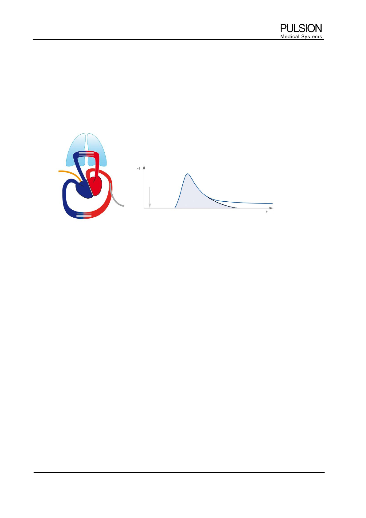
2.1 Principle
To accomplish thermodilution determination a known volume of a suitable indicator (at least 10°C below blood
temperature) is injected intravenously as quickly as possible. The recorded downstream temperature change
is dependent on the flow and the volume through which the cold indicator has passed. As a result, a
thermodilution curve can be recorded. The PiCCO
2
detects the cold indicator in the arterial system (preferably
in the femoral artery).
Figure 1: Heart-lung circulation and resulting thermodilution curve
2.2 Transpulmonary Cardiac Output
Cardiac Output (CO) is the volume of blood being pumped by the heart in one minute.
Cardiac output by thermodilution is calculated according to the Stewart-Hamilton formula (see Appendix)
using the area under the thermodilution curve.
Absolute Parameters Indexed Parameters
Parameter Abbr. Unit Abbr. Unit
Cardiac output, transpulmonary CO l/min CI l/min/m
2

Principles of Measurement and Parameters
Operator´s Manual PiCCO
2
Page
Version 3.1 B-3
2.3 Transpulmonary volume determination
Specific volumes can be calculated by multiplying cardiac output with characteristic time variables of the
thermodilution curve.
The parameters can alternatively be displayed as absolute parameters or indexed to the patient´s body
characteristics.
The PiCCO
2
uses predicted body weight (PBW) to index intrathoracic volumetric parameters.
Absolute Parameters Indexed Parameters
Parameter Abbr. Unit Abbr. Unit
Global End-Diastolic Volume GEDV ml GEDI ml/m
2
Extravascular Lung Water EVLW ml ELWI ml/kg
Global Ejection Fraction GEF %
Pulmonary Vascular Permeability Index PVPI -
Cardiac Function Index CFI 1/min
Intrathoracic Blood Volume ITBV ml ITBI ml/m
2
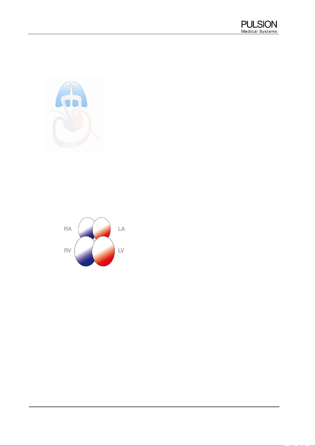
2.3.1 GEDV / ITBV
GEDV ITBV
Figure 2: GEDV / ITBV
Global End-Diastolic Volume (GEDV) is the total amount of blood left in all four heart chambers, i.e. atria and
ventricles, at the end of diastole.
Intrathoracic Blood Volume (ITBV) represents the total amount of blood in the thorax.
GEDV and ITBV reflect the circulatory volume status and are excellent indicators of cardiac preload. GEDV
and ITBV are used for managing the patient´s vascular filling status and guiding volume therapy.
CAUTION: Aortic aneurysms may cause the displayed blood volume (GEDV/ITBV) derived by
thermodilution measurement to be erroneously high.
Principles of Measurement and Parameters
Page B-4 Operator’s Manual PiCCO
2
Version 3.1
2.3.2 EVLW
EVLW quantifies the extravascular fluid volume in the lungs. It is used to alert the clinician to the existence or
development of pulmonary edema. When measuring lung water the intra-alveolar, intracellular and interstitial
lung water are considered. However, a pleural effusion does not influence measurements.
Figure 3: Extravascular Lung Water (EVLW)
2.3.3 Additional Thermodilution Parameters
2.3.3.1 GEF:
GEF mainly depends on right and left ventricular contractility and can be used to detect right and/or left
ventricular dysfunction. GEF is derived from the ratio of four stroke volumes divided by Global End-
Diastolic Volume (GEDV).
Figure 4: Global Ejection Fraction (GEF)
2.3.3.2 CFI:
CFI represents the ratio between cardiac output and global end-diastolic volume (GEDV).
2.3.3.3 PVPI
PVPI shows the relationship between EVLW and PBV (Pulmonary Blood Volume) and can help to
distinguish between hydrostatic and permeability caused pulmonary edema.
Principles of Measurement and Parameters
Operator´s Manual PiCCO
2
Page
Version 3.1 B-5
3 Continuous Pulse Contour Analysis
3.1 Principle
The relationship between blood flow out of the aorta and pressure measured near the aorta (femoral artery or
other large artery) is determined by the compliance function. The compliance function can therefore be
characterized by measuring blood pressure and blood flow (cardiac output) simultaneously. Transpulmonary
thermodilution cardiac output determined simultaneously with continuous arterial pressure measurement is
utilized to calibrate the pulse contour analysis to each individual patient´s aortic compliance function.
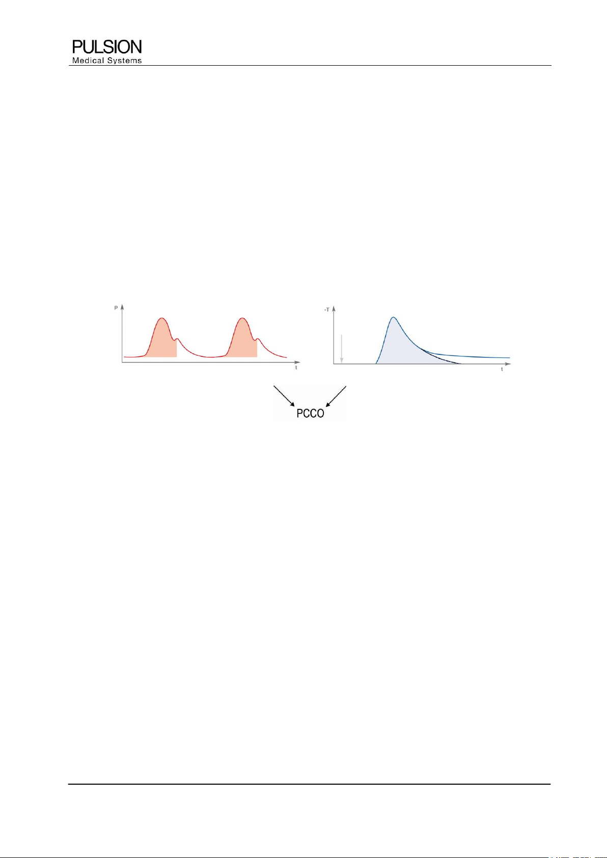
3.2 Calibration of the Pulse Contour Cardiac Output
To calibrate the measurement of continuous cardiac output, a reference thermodilution cardiac output is
necessary. The PiCCO
2
uses the transpulmonary thermodilution as reference method.
Figure 5: Calibration of pulse contour analysis by means of thermodilution

Principles of Measurement and Parameters
Page B-6 Operator’s Manual PiCCO
2
Version 3.1
3.3 Continuous haemodynamic determination
The following parameters are derived by the PULSION PiCCO
2
, analyzing the arterial pressure curve beat by
beat. The parameters can alternatively be displayed as absolute parameters or indexed to the patient´s body
characteristics.
Absolute Parameters Indexed Parameters
Parameter Abbr. Unit Abbr. Unit
Pulse Contour Cardiac Output PCCO l/min PCCI l/min/m
2
Stroke Volume SV ml SVI ml/m
2
Systemic Vascular Resistance SVR dyn•s•cm
-5
SVRI dyn•s•cm
-5
•m
2
Stroke Volume Variation SVV %
Pulse Pressure Variation PPV %
Left Ventricular Contractility dPmx mmHg/s
Cardiac Power Output CPO W CPI W/m²
Heart Rate HR min
-1
Mean Arterial Blood Pressure MAP mmHg
Systolic Arterial Blood Pressure APsys mmHg
Diastolic Arterial Blood Pressure APdia mmHg
Moreover, central venous pressure (CVP) in mmHg can be measured continuously.
3.3.1 MAP / CVP / HR
MAP (Mean Arterial Pressure)
Mean arterial pressure is the mean value of the blood pressure in the arterial system.
CVP (Central Venous Pressure)
Central venous pressure is the average blood pressure directly before the right heart.
HR (Heart Rate)
Heart rate is the number of heart beats per minute.
3.3.2 PCCO
Pulse contour cardiac output is the continuously determined cardiac output from the pulse contour analysis.
CAUTION: As the pulse contour cardiac output of children has not been sufficiently validated thus
far, the CO should be checked by thermodilution before therapeutic interventions.
Recalibration is recommended with significant changes in haemodynamic conditions, such as
volume shifts or changes to medication.
Principles of Measurement and Parameters
Operator´s Manual PiCCO
2
Page
Version 3.1 B-7
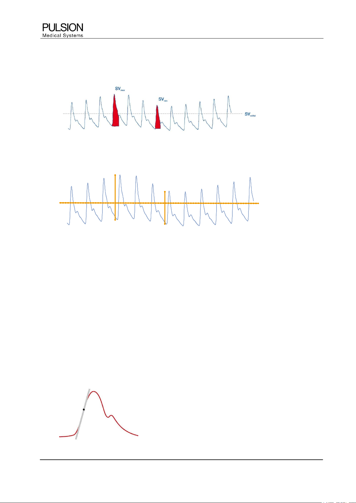
3.3.3 SVV / PPV
SVV is the variation in stroke volume over a certain time.
Figure 6: SVV
PPV is the variation in pulse pressure over a certain time.
PP
PP
max
max
PP
PP
min
min
PP
PP
max
max
PP
PP
min
min
Figure 7: PPV
In mechanically ventilated patients without arrhythmias SVV and PPV enable an estimation of the volume
responsiveness. Large variations in stroke volume or pulse pressure induced by mechanical ventilation
indicate that volume loading will lead to an increase in cardiac ejection (volume responsiveness).
3.3.4 SVR
SVR represents the resistance the blood encounters as it flows through the vascular system. The SVR value
is often used by clinicians as an estimate of afterload.
3.3.5 CPO
The CPO is the product of cardiac output and mean arterial pressure, thus reflecting the cardiovascular blood
flow related to the counteractive resistance. CPO serves as an indicator for the overall performance of the
heart.
3.3.6 dPmx
dPmx is the abbreviation for ΔP
max
/Δt. This parameter indicates how fast the aortic pressure is rising during
systole. It allows a close approximation of the contractility of the left ventricle. In addition to CFI/GEF, dPmx
can be used to manage the administration of positive inotropic and cardiovascular agents.
Figure 8: dPmx
Principles of Measurement and Parameters
Page B-8 Operator’s Manual PiCCO
2
Version 3.1
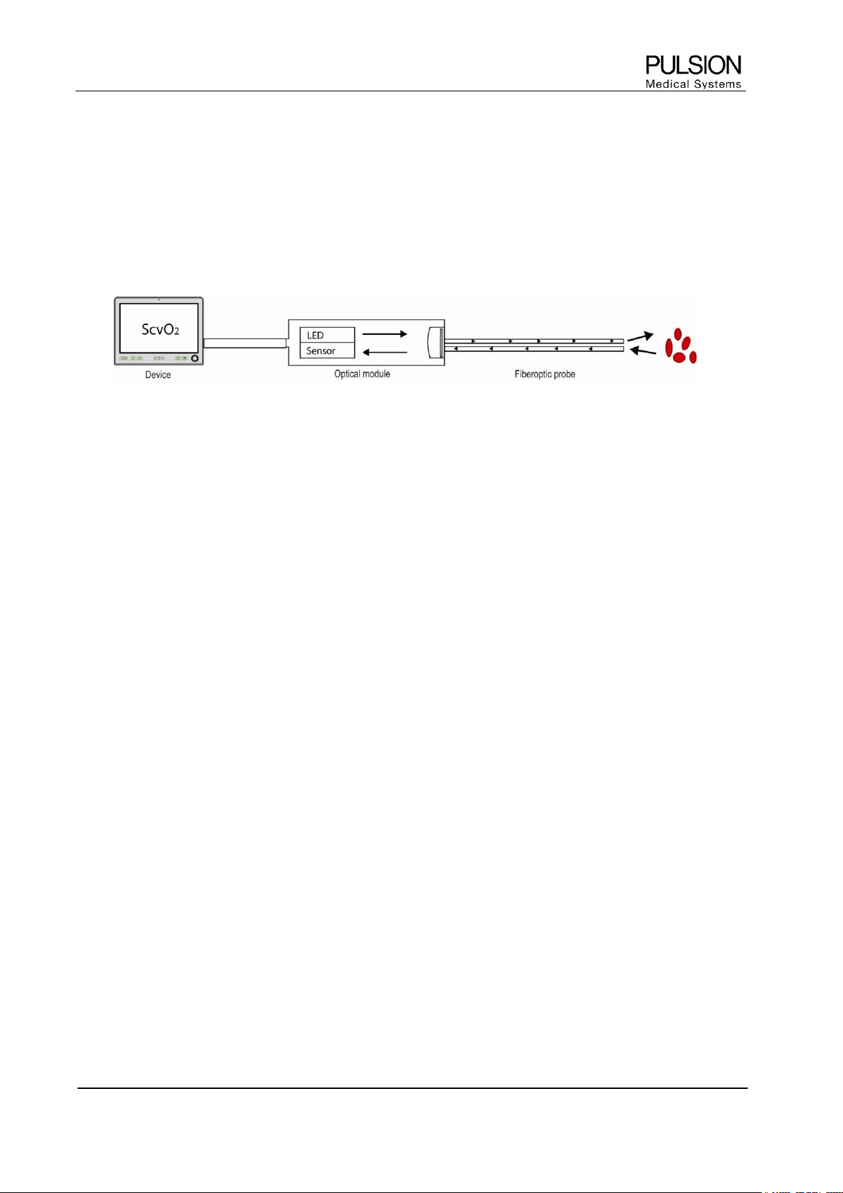
4 Central venous oximetry
4.1 Principle
The PiCCO
2
measures central venous oxygen saturation (ScvO
2
) by spectrophotometry. Spectrophotometry
involves the use of light emitting diodes (LED) that produce light of various wavelengths in red and infrared
spectra. The light is transmitted to the blood through a fiberoptic in the probe, reflected off the red blood cells
and transmitted back through a separate fiberoptic to an optical module.
Figure 9: The principle of spectrophotometry
The wavelengths are selected in a way that the absorption characteristics of haemoglobin and
oxyhaemoglobin are different. Given both the amount of total haemoglobin and the amount of haemoglobin
bound to oxygen, oxygen saturation can be calculated.
4.2 Determination of ScvO
2
ScvO
2
reflects the oxygen saturation of the haemoglobin in the blood in the superior vena cava directly before
the right atrium. It is an early indicator of an imbalance between oxygen delivery and oxygen consumption.
Thus this parameter early indicates a threat to global tissue oxygenation.
Absolute Parameters
Parameter Abbr. Unit
Central Venous Oxygen Saturation ScvO
2
(%)
4.3 Oxygen delivery and oxygen consumption: DO
2
and VO
2
Absolute Parameters Indexed Parameters
Parameter Abbr. Unit Abbr. Unit
Oxygen delivery DO
2
ml/min DO
2
I ml/min/m
2
Oxygen consumption VO
2
ml/min VO
2
I ml/min/m
2
4.3.1 DO
2
DO
2
is the amount of oxygen provided to the tissue per minute. It depends on the flow (cardiac output), the
amount of haemoglobin in the blood and the arterial oxygen saturation.
4.3.2 VO
2
VO
2
is the amount of oxygen consumed by the tissue per minute.
Principles of Measurement and Parameters
Operator´s Manual PiCCO
2
Page
Version 3.1 B-9
5 Pulse oximetry and pulse dye densitometry
5.1 Principle of pulse oximetry
Pulse oximetry measures the percentage oxygen saturation of the haemoglobin. The principle of pulse
oximetry is based on the transmission and absorption of light waves in the visible and near-infrared spectrum
by haemoglobin. Light of different wavelengths is sent through the tissue non-invasively and is subsequently
detected by a sensor. The received light signal is used to determine the oxygen saturation. This measurement
is entirely non-invasive.
Pulse oximetry is used to measure the partial oxygen saturation of haemoglobin i.e. only oxygenated and
deoxygenated haemoglobin is included. However, not included is e.g. carboxyhaemoglobin or
methaemoglobin.
WARNING: External influences: carboxyhaemoglobin can result in incorrect high values for SpO
2
.
The degree of elevation is approximately equal to the amount of carboxyhaemoglobin present.
Dye (e.g. Indocyanine Green) or other substances which contain dyes which usually modify the
light absorption capacities, can lead to faulty measurement values of the oxygen saturation.
WARNING: The measurement of SpO
2
is not recommended for patients weighing less than
20 kg (44lbs).
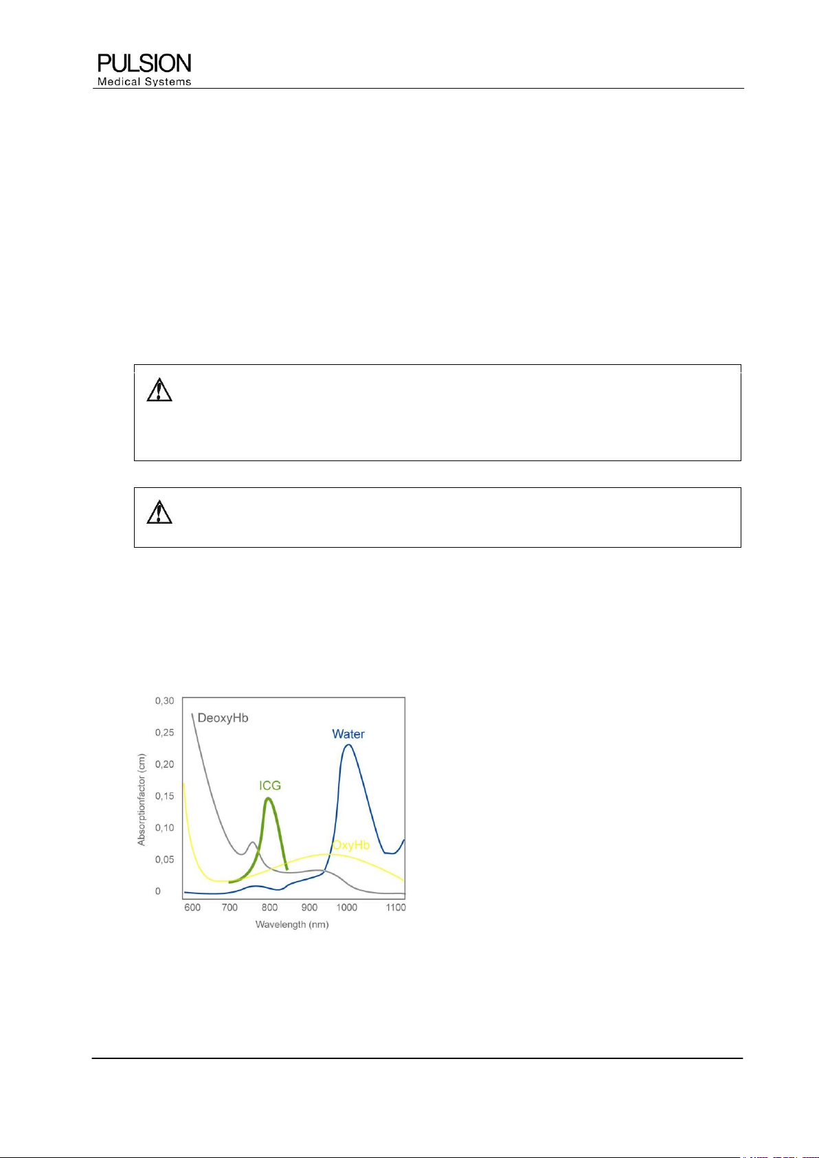
5.2 Principle of pulse dye densitometry
The principle of pulse dye densitometry and with it, the measurement of the plasma disappearance rate of
Indocyanine Green (ICG) is based on pulse oximetry. The difference is that other light wavelengths are used
than with pulse oximetry.
Figure 10: Absorption spectra of O
2
Hb, Hb and ICG (According to Britton Chance, University of Pennsylvania)
Principles of Measurement and Parameters
Page B-10 Operator’s Manual PiCCO
2
Version 3.1
5.3 Principle of ICG elimination detection
ICG has an absorption maximum of approximately 805 nm. The determination of ICG concentration within this
range (optical window) is not disturbed by other blood components.
The trend in ICG concentration over time is used to calculate the relative change in percent per minute. The
plasma disappearance rate (PDR) of ICG is a measure of the excretory capacity of the liver and thus global
liver function. It is influenced by the function of liver cells as well as the liver perfusion. Depending on the
patients underlying disease the PDR helps to assess the patient´s liver function and/or liver perfusion. As the
liver is part of the splanchnic area, splanchnic perfusion can be indirectly estimated.
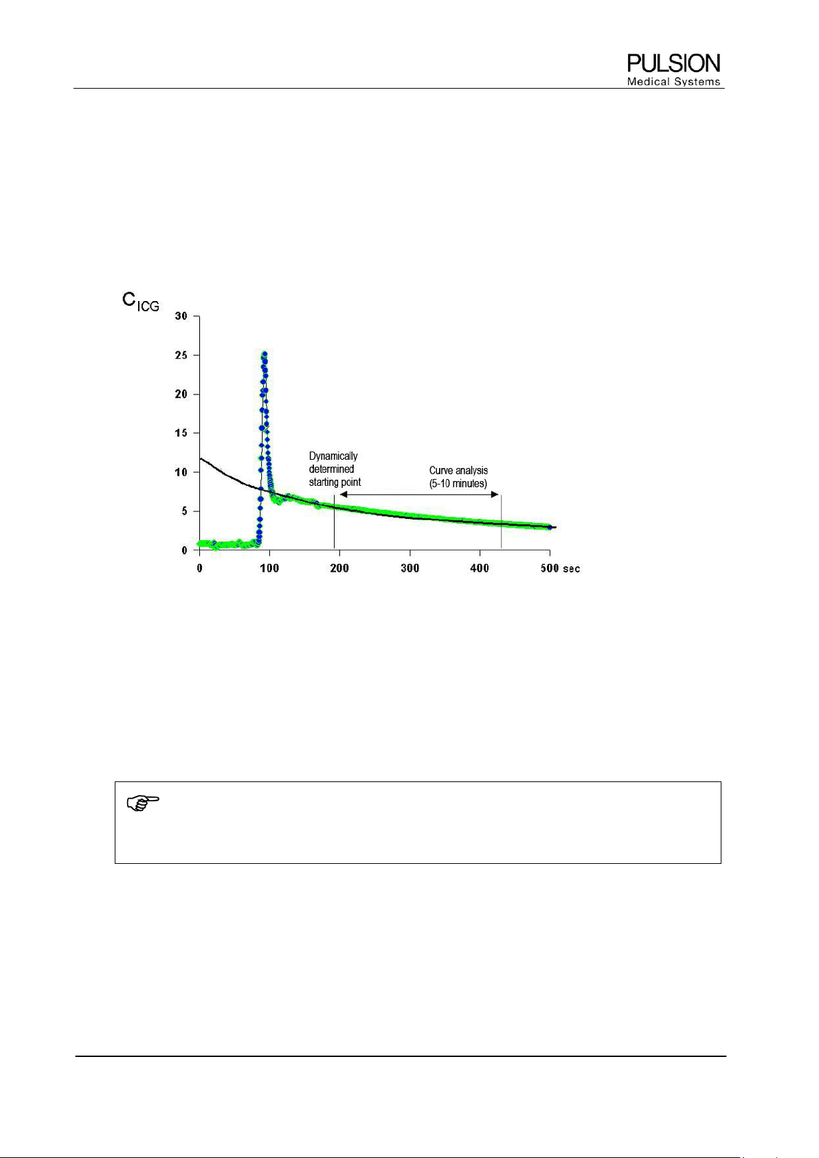
Figure 11: Schematic representation of the ICG elimination curve
The figure above shows a typical ICG concentration curve with the initial peak and its course over
500 seconds. The elimination measurement starts after thorough mixing of ICG with the circulating blood
volume. The starting point of the PDR measurement is determined dynamically dependent on the circulation
time derived from the first peak. The ICG curve analysis continues for five to ten minutes, dependent on the
quality of the curve.
The starting point represents 100%. The algorithm detects a percentage decrease per minute and indicates
the PDR in percent per minute.
NOTE
For information on the diagnostic drug, Indocyanine Green, please refer to the corresponding
SPC (summary of product characteristics) or PIL (patient information leaflet) of ICG.
5.4 Parameters of pulse oximetry and pulse dye densitometry
The following parameters are measured by pulse dye densitometry and pulse oximetry:
Arterial oxygen saturation SpO
2
(%)
Plasma Disappearance Rate of ICG PDR (%/min)
Retention Rate of ICG after 15 minutes R15 (%)
Principles of Measurement and Parameters
Operator´s Manual PiCCO
2
Page
Version 3.1 B-11
6 Parameter groups and ranges of normal values
The normal value ranges are based upon clinical experience and can vary from patient to patient. The stated
values are therefore offered without guarantee. Indexed parameters are related to body surface area,
predicted body weight or predicted body surface area (see Appendix) and can also be displayed as absolute
values.
Parameter
Normal Ranges
Unit
Flow
CI / PCCI
3.0 – 5.0
l/min/m
2
SVI
40 – 60
ml/m
2
Preload Volume
GEDI
680 – 800
ml/m
2
ITBI
850 – 1000
ml/m
2
SVV
< 10
%
PPV
< 10
%
Afterload
SVRI
1700 – 2400
dyn•s•cm
-5
•m
2
Contractility
GEF
25 – 35
%
CFI
4.5 – 6.5
1/min
dPmx
-
mmHg/s
Organ Function
ELWI
3.0 – 7.0
ml/kg
PVPI
1.0 – 3.0
-
CPI
0.5 – 0.7
W/m
2
PDR
18 – 25
%/min
R15
0 – 10
%
Oxygenation
ScvO
2
70 - 80
%
DO
2
I
400 – 650
ml/min/m
2
VO
2
I
125 – 175
ml/min/m
2
SpO
2
90 – 100
%
NOTE
PULSION is a medical device manufacturer and does not practice medicine. PULSION does not
recommend these values for use on a specific patient. The treating physician is in any case
responsible for determining and utilizing the appropriate diagnostic and therapeutic measures for
each individual patient.

Principles of Measurement and Parameters
Page B-12 Operator’s Manual PiCCO
2
Version 3.1
WARNING: The PiCCO
2
equipment may only be regarded as a device providing early warning. If
there is an indication of a trend towards de-oxygenation of the patient, blood samples must be
taken and tested on a laboratory oximeter in order to arrive at a decision concerning the condition
of the patient.
The device must not be used for monitoring breathing.
The device must not be used for monitoring heart rate, arterial blood pressure and body
temperature.
Installation and setup
Operator´s Manual PiCCO
2
Page
Version 3.1 C-1
C Installation and setup
CAUTION: The user must assure him-/herself of the safe and fully functional condition of the
equipment before using it.
1 Unpacking and inspection
Inspect the packaging for possible shipping damage. Use care when unpacking the PiCCO
2
. Retain the
packing slip and save all packing material in case the device is damaged or fails the self test and has to be
returned to the manufacturer.
WARNING: Before using the PiCCO
2
equipment carefully read the operating instructions for the
device and the used disposables. The use of the PiCCO
2
in contradiction to the instructions in this
manual may cause undue equipment failure and possible health hazards.
Position the equipment in such a manner that neither the device nor other equipment attached to
the device can fall on the patient. Never lift or carry the device by the mains supply cable or the
cable attached to the patient.
When using the provided assembly facilities pay attention to a correct installation. The used
system must be sufficiently stable and tilt resistant as well as medically approved. In order to
ensure a secure connection with the mounting system the locking mechanism of the universal
adapter plate must be completely snapped in place.
CAUTION: If the PiCCO
2
appears to be damaged, contact your local PULSION representative.
Do not use the PiCCO
2
if the device appears to be damaged.
If the system check detects a failure, no function will be available and “SERVICE” is displayed on
the screen. Turn the PiCCO
2
off and contact your local PULSION representative. Do not attempt to
use or repair the PiCCO
2
.

Installation and setup
Page C-2 Operator’s Manual PiCCO
2
Version 3.1
- Blank page -
Installation and setup
Operator´s Manual PiCCO
2
Page
Version 3.1 C-3
2 Functionality and user interaction
2.1 Screen elements
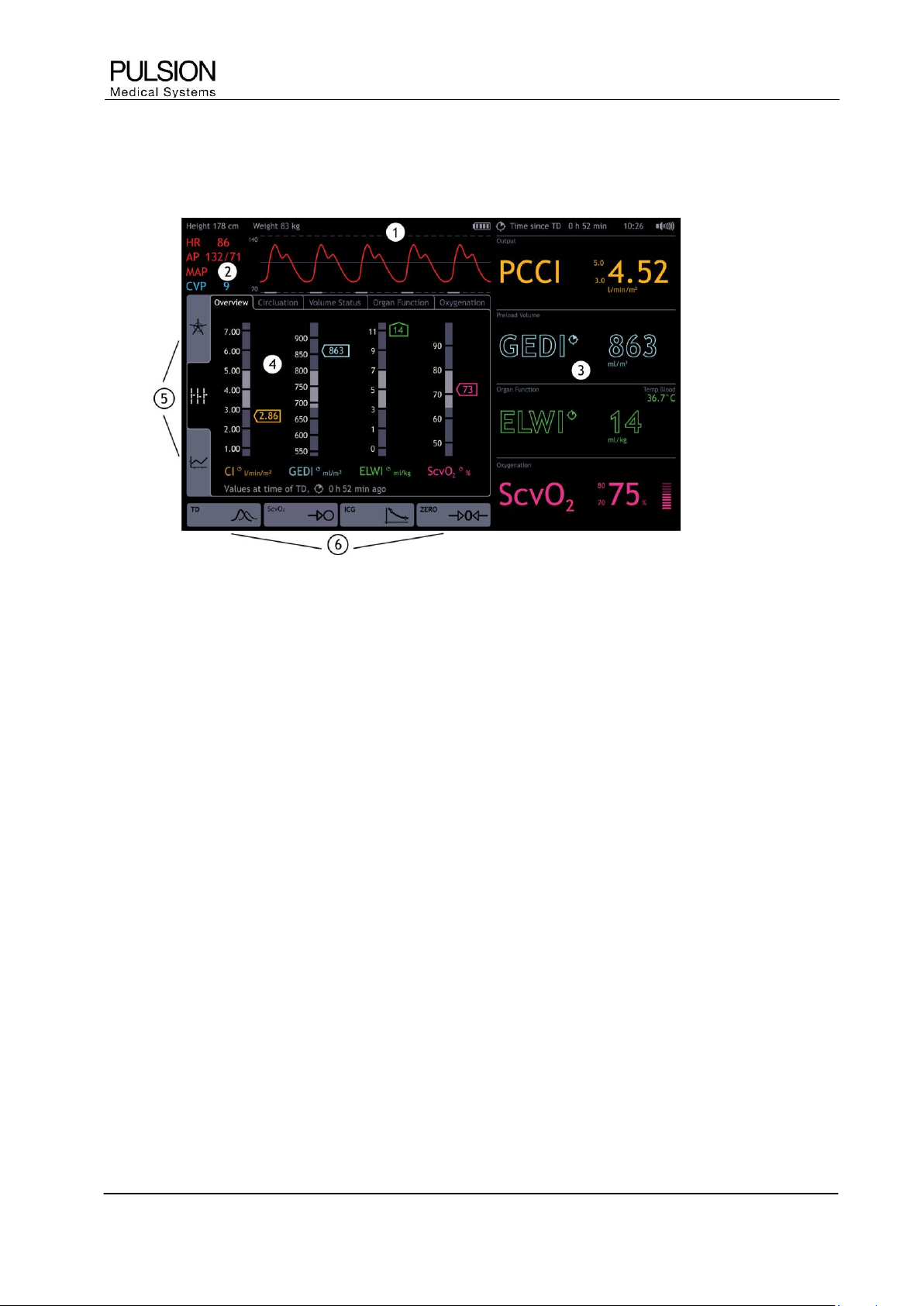
Figure 12: Screen elements
1) Information bar
Information bar for patient and measurement specific information and error messages
2) Real Time pressure curve
Permanent display of real time pressure curve of arterial pressure (AP) and central venous pressure (CVP)
3) Parameter fields
Configurable parameter fields divided into parameter groups, permanent display of the selected parameters
4) Patient screen
Function area for measurements, configuration and graphical display of parameters
5) Display options
The determined parameters can be displayed in 3 different ways. (for details see chapter C4)
6) Selection of actions
Direct access to thermodilution measurement, ScvO
2
calibration, ICG measurement and zero adjustment of
blood pressure (dependent on setting and connected module)
2.2 User interaction
The PiCCO
2
provides an intuitive user interface and can be operated by both navigation dial and touch
screen. In order to keep navigation as easy as possible, actions and settings can be done by direct activation
of the respective screen element on the screen.

Installation and setup
Page C-4 Operator’s Manual PiCCO
2
Version 3.1
2.2.1 Touchscreen
Measurement and display options as well as any configuration can be reached directly by touching the
respective element on the touch screen. All input can be directly made on the screen. Numerics can be
directly entered on the screen by means of a touch keyboard.
To switch to another screen just select another element on the screen or use the Main button.
2.2.2 Function keys
Figure 13: Function keys
ON/OFF key: This key is used to switch the device on and off. As soon as the mains power switch is pressed
at the rear side of the device, a green light appears. The green light indicates that the device is connected to
the mains power supply. A blinking green light indicates that the battery is being charged. By pressing the key
continuously for 4 seconds during operation, the device will shutdown and restart.
Opening the help screen
Print key: Starts a printout, depending on the connected printer device (USB or thermal transfer printer)
Mute key: Pausing of the alarm for 2 minutes. The orange light indicates an alarm even if there is an acoustic
alarm pause.
 Loading...