

Page 1
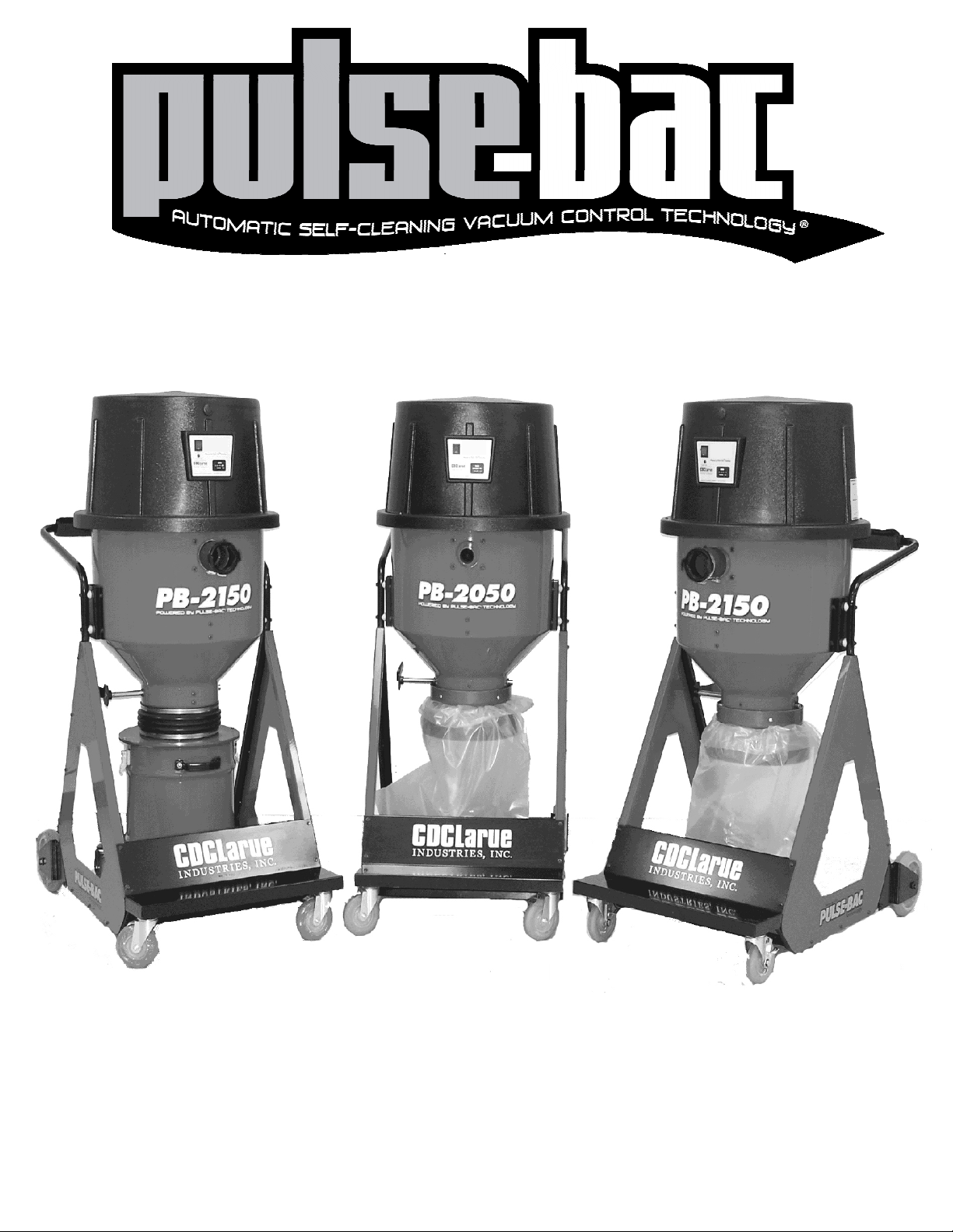
Never Stop To Unclog Filters Again!
Operation & Service Manual
Models: PB-2050 and PB-2150
Page 2

Table of Contents:
CONTENTS: PAGE:
Packaging & Shipping…………………….………………………………..…………..
Introduction.. ………………………………………………………….…….…………..
Important Safety Instructions………………………………………...………………...
Important Safety Instructions Continued…………………………...…..…………….
Specifications, Patents & Awards………….….....…………………………………...
Specifications Continued……………………………………………………………….
Operating Instructions……………………………………………………...…………..
Exclusive Tank Chamber Sensor ……………………………………………………..
Emptying The Dust Storage Tank…………………………………………..…………
Dust Collection Bag removal…………………………………………………………..
Filter Removal ……………...………………………………………………………….
Filter Installation / Trouble Shooting………………………….……………………….
..
Printed Circuit Board Overview………………………………………………………..
Electrical Block Diagram………………………………………….….. ……………….
Printed Circuit Electrical Schematic…………………………………………………...
Servicing the PB-2050 and PB-2150………………………………………………….
Motor Replacement
Servicing the PB-2050 and PB-2150 Continued…………………………………….
Printed Circuit Board Replacement
Valve Solenoid Replacement…………………………………………………………..
Figure 1. Motor assembly……………………………………………….……………...
Notes……………………………………………………………………………………..
Warranty………………………………………………………………………………….
3
4
5
6
7
8
9
10
11
12
13
14
15
16
17
18
19
20
21
22
23
Copyright © 2009
CDCLarue Industries, Inc.
2
Page 3
Packaging & Shipping
The Pulse-Bac 2000 Series Dust Collection Equipment comes
shipped on a 48”x 45” pallet, bolted down and held in place
by two 16 gauge steel plates located in the front and back,
underneath the bottom platform. You will need to have a 7/16
socket wrench to remove the dust collector from the pallet.
First inspect your new Pulse-Bac for
any damage during shipping. Check
the following:
1. Check for visual damage, if visual damage is apparent have the driver note that on the Bill of Laden. If
the driver has left the facility before visually inspecting the equipment and damage is apparent, immediately call the shipper and have them return to inspect
and note the damage. Whenever possible note the
damage by taking pictures. This will aid you if a claim
must be submitted for damage or replacement.
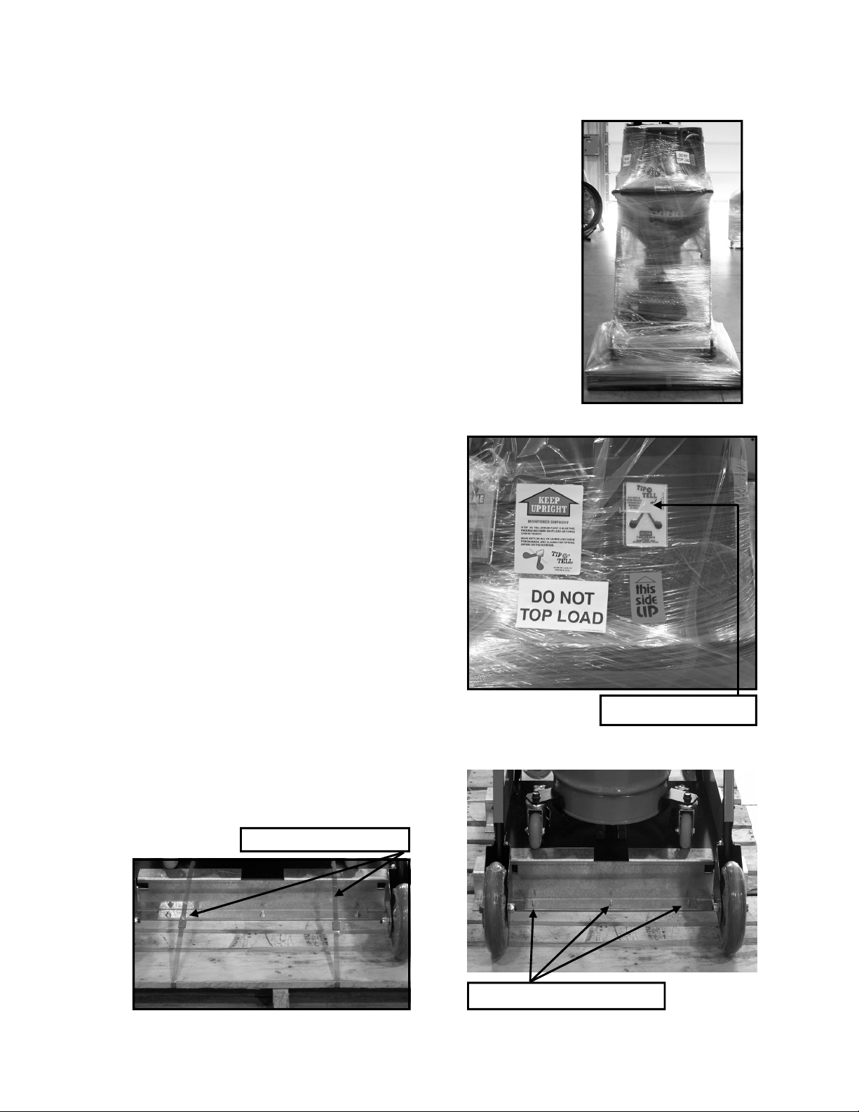
2. Check your “ Tip-N-Tell” label placed on the top of
the shipment. This label is located at the top of the
hood, and has two reservoirs of blue glitter, if that
glitter is anywhere in the upper reservoir where the
blue arrow is pointing, this needs to be noted on the
BOL. This could mean that the shipment was tipped
over during transit. (See Figure 1.)
3. After inspecting shipment, remove the plastic wrap.
4. After removing wrap, cut the two straps on the
bottom. (See Figure 2.)
5. Using your 7/16 Socket wrench, remove the three
nuts located underneath the bottom platform. (See
Figure 3.) repeat this on both the front and back
steel plates.
6. Once you have removed the nuts, slowly and gently
to avoid scratching the powder coated finish, remove
the steel plates. After removing front and back steel
plates your Pulse-Bac® should be ready to be removed from the pallet.
7. After removing your new PB-2150 or PB 2050 keep
and save the pallet and steel plates for return if
needed in the future for servicing.
Figure 1.
Figure 3.
Tip-N-Tell Reservoir
Figure 2.
Cut Straps & Remove
Remove nuts from steel plate
3
Page 4

Introduction:
Congratulations, you have purchased the latest innovation in commercial portable dust
collection equipment. This manual will help you to understand and operate your new
Pulse-Bac® PB-2050 or PB-2150.
The PB-2050 & PB-2150 are shipped ready to use, however you should make an initial
inspection to insure that no damage has occurred during shipping. You should also take the
time to familiarize yourself with the proper use and operation of your new PB-2050 or PB-2150.
Safety is paramount when operating any machinery. Safety is a combination of common
sense, knowing the proper use and operation of the equipment you are operating and staying
alert when operating the equipment. Read this operator’s manual and understand it so that you
are familiar with the operation and proper use of your new Pulse-Bac PB-2050 or PB-2150.
Familiarizing yourself with the proper operation and use of your new PB-2050 or PB-2150 will
help to avoid costly mistakes.
Both the PB-2050 and PB-2150 are equipped with the most advanced automatic self-cleaning
vacuum filtration technology available for portable dust collection equipment. Our exclusive
Pulse-Bac Technology internally flushes the filters clear of dust and debris using only ambient
air and vacuum while the PB-2050 or PB-2150 is in operation. This revolutionary design ensures that your dust collector will not clog the filters; thereby preventing the loss of suction
(LIFT) or CFM (air volume) during operation. the PB-2050 and PB-2150 are fully automatic,
self cleaning dust collectors, with no need for shakers, blowers, compressors or buttons to
push, just turn it on and the PB-2050 and PB-2150 dust collectors automatically eliminate airborne dust associated with grinding, sanding, cutting or any other dust producing situations. In
addition, both the PB-2050 and PB-2150 are equipped with the industries first Tank Capacity
Sensor (TCS) system. The revolutionary TCS™ system prevents the operator from over filling
the PB-2050 or PB-2150 collection tank, helping to prevent damage to the filter and vacuum
motor components.
The PB-2050 and PB-2150 come equipped with our patent pending P.T.F.E. Spun Bond
Polyester twist on filters, capable of capturing dust particles as small as .1 micron in size, an
ergonomic cart that can fit through any standard 30” door, four non-marking caster wheels
with locks and dual sealed collection tanks that allow for debris removal without stopping
dust collection activities to empty the dust in the collection tank.
Thank you for your purchase of today’s most advanced industrial dust collection equipment, if
you have any questions regarding this manual or require any assistance please call customer
service at 866.954.9700.
4
Page 5
Important Safety Instructions:
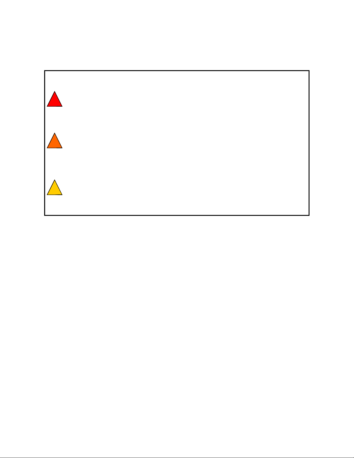
Failure to read and observe all DANGER statements
DANGER
WARNING
CAUTION
could result in sever bodily injury or death. Read and
observe all DANGER statements found in your operators
manual and on your machine.
Failure to read or observe all WARNING statements could
result in injury to you or to other personnel, and property.
Read and observe all WARNING statements found in the
manual and on the machine.
Failure to read and observe all CAUTION statements
could result in damage to the machine or to property.
Read and observe all CAUTION statements found in your
operators manual and on your machine.
General Safety:
1. Equipment is to be operated by trained and qualified personnel only.
2. Always read and follow the operating and safety procedures.
3. Always use qualified personnel when repairing or maintaining equipment.
4. This equipment must be used for the purpose for which it is intended. Any other use
will void the warranty and could cause bodily injury to the operator and or damage
to the equipment.
5. If a malfunction should occur, turn the machine off immediately and correct the
problem before restarting the machine.
6. Do not operate under the influence of alcohol or drugs.
7. Avoid lifting the tank when filled with heavy dust or any other heavy material
Import! Please Read and Understand The Following Carefully.
Static Shocks are common and occur in dry areas or when the relative humidity of the ambient air is
low. Be aware of low humidity conditions and if static shocks are persistent, order and use a static
reduction hose to operate the unit. CDCLarue recommends anyone using the PB-2050 or PB-2150 for
collection of materials such as wood or plastic should always use a static reduction hose. Wood and
plastic particles create static electricity even when the ambient air has high humidity.
Remember, Always stay alert and drug free when using any electrical equipment.
5
Page 6
Important Safety Instructions Continued:
Extension cord Usage:
When using an extension cord to operate the PB-2050 or PB-2150, always use the
proper size extension cord. The following chart will help you in your selection of the
proper size extension cord for operating your PB-2050 or PB-2150. Please note when
using an improper extension cord you may cause damage to your equipment and void
the warranty.
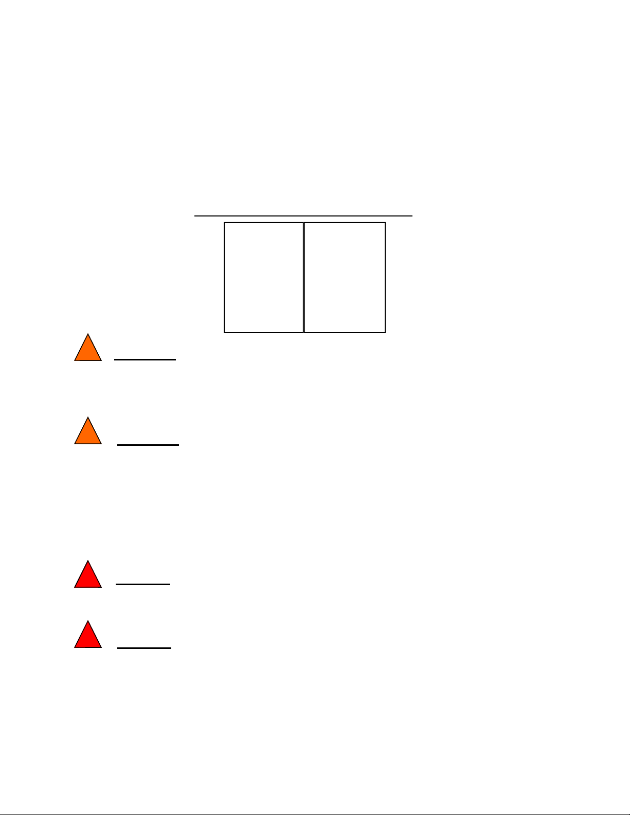
Warning:
To reduce the risk of back injury or falls, do not try to lift an over filled collection tank. If you have over
filled the collection tank, scoop enough contents out to make the tank light enough for one person to
comfortably lift and empty the tank.
Warning:
Both the PB-2050 and the PB-2150 are equipped with a Tank Capacity Sensor (TCS) this exclusive feature keeps the main collection tank from being overfilled, which can cause damage to filters and motors.
The operator must be aware that the TCS™ turns off the power to the main vacuum motor and causes
an audio and visual alarm when the tank is close to being over filled. The operator should be aware of
the fact that the main vacuum motor can restart as soon as the overfilled tank situation is remedy and
therefore the operator could be surprised and possibly cause an injury by being alarmed at the sound of
the motor restarting.
Danger:
Sparks generated by the dust collector’s main vacuum motor can ignite flammable vapors or air born
dust.
Danger:
To reduce the risk of fire or explosion, never use the PB-2050 or the PB-2150 near flammable or combustible liquids, gases, or explosive fluids like gasoline, lighter fluids, flammable cleaners, oil based
paints, natural gas, hydrogen, coal dust, magnesium dust, grain dust, gun powder or other types of flammable vapors or fuels. If you are in doubt as to the proper use of your PB-2050 or PB-2150 call
CDCLarue™ customer service department at 1-866-954-9700.
Proper Extension Cord-Gage and Length
Extension Cord
Length.
——————
0-25 Ft.
50 ft.
100 ft.
Wire Gauge
(A.W.G.)
—————–—
14
12
10
6
Page 7
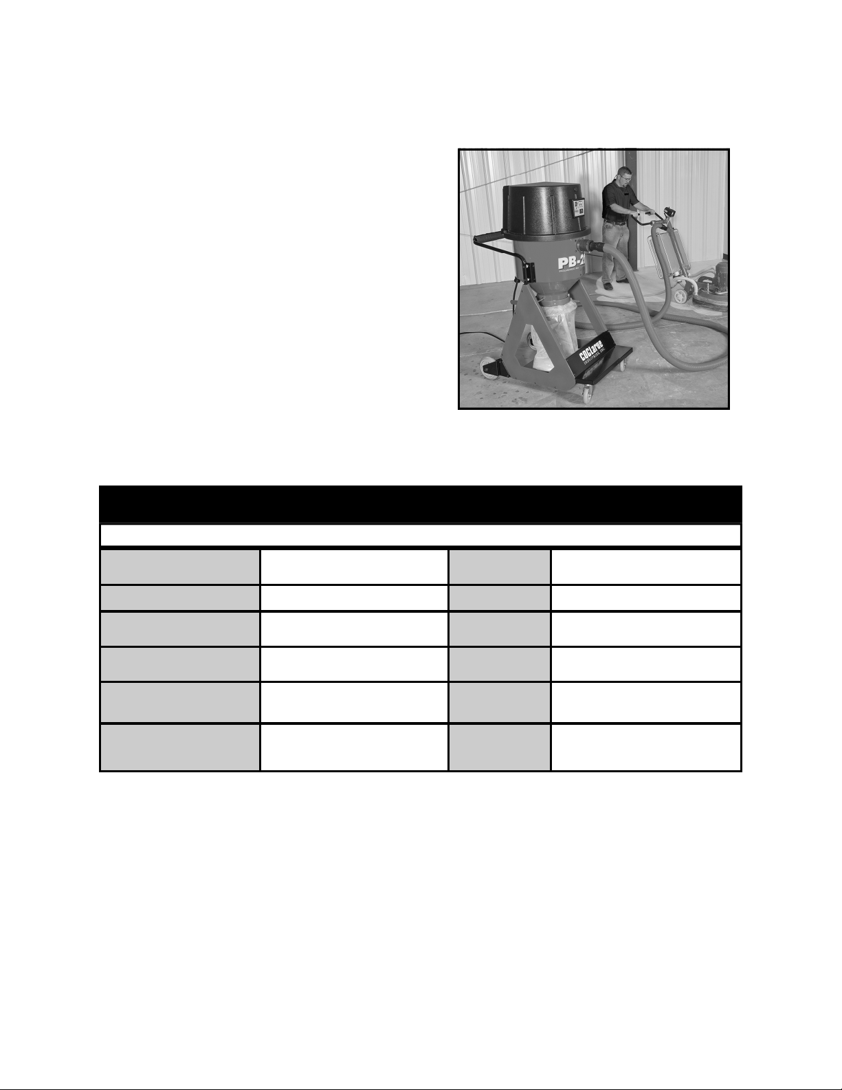
Specifications, Patents and Award Information:
The PB-2050 and PB-2150 are specifically designed for dust collection applications that require high levels of lift (suction) and CFM (Air
flow rate). Both the PB-2050 and the PB-2150
dust collectors from CDCLarue™ utilize our
exclusive Pulse-Bac® Technology, preventing
the filters from clogging and losing lift, automatically. As well as additional features that make
unloading the dust from the dust collection
tanks easy and convenient for the operator.
CDCLarue patent pending dust valve design,
allows the PB-2050 and PB-2150 to remain in
operation while the lower collection tank is removed to discard dust and debris. This
unique design helps in reducing downtime, increases productivity and lowers maintenance cost.
Specifications PB-2150
Model
Filtration System
Filters
Motor
Performance
Vacuum Port Inlet
Pulse-Bac PB-2150 with Tank
Sensor.
Patented Pulse-Bac Technology
5 ea. Twist-on/off 100% Spun Bond
Polyester PTFE Coated
Ametek, Tangential Bypass.
311 CFM, 70” Lift
3” inlet with manual hose lock
Voltage
Current
Dimensions
Weight
Dust Storage
Tank
Casters
220/230 Volts 50/60 Hz
Single Phase
7.9 Amps
63”H x 29”W x 45”D
220 Lbs
8 Gal. Tank with cart.
Non-Marking, & Conductive. 5” in
back, 3” swivel in front with wheel
locks.
Patents & Awards:
US Patent # 7082640B2 and other patents pending.
Pulse-Bac Technology-Most Innovative Product, World of Concrete 2005 & 2008.
Pulse-Bac Technology-Innovative Product Award, Rental Equipment Register 2004.
7
Page 8
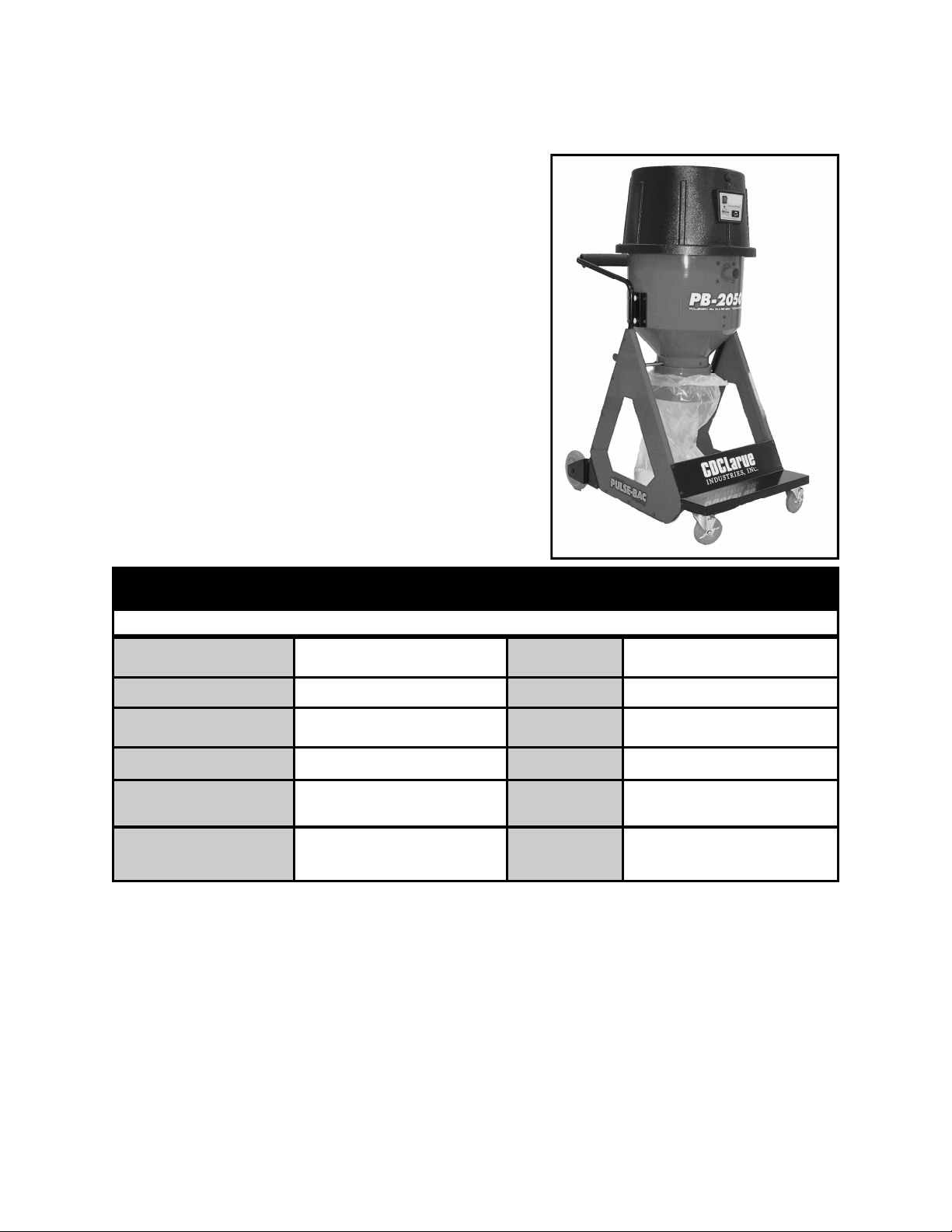
Specifications Continued:
The PB-2050 and PB-2150 are equipped with
CDCLarue™ exclusive Tank Capacity Sensor
(TCS). The TCS™ is located in the upper collection
tank. TCS keeps the operator from over filling the
upper collection tank and extends the life of the
filters and motor on both models.
The TCS feature lowers the possibility of dust
accumulating and facing the filters over a period of
time due to the operator allowing the tank to be
overfilled. In addition the TCS will prevent the lower
dust collection tank from becoming overfilled,
eliminating another source of airborne dust
caused from overfilled collection tanks and spills.
TSC also helps to ensure that the lower tank or bag
when filled will not weigh more than forty pounds.
Specifications PB-2050
**
OPTIONAL ACCESSORIES
Model
Filtration System
Filters
Motor
Performance
Vacuum Port Inlet
The PB-2050 and PB-2150 also incorporate another exclusive feature developed by
CDCLarue, each model is equipped with our patent pending Cyclonic Debris Management System (CDM). The CDM™ system reduces the amount of debris the filters are
exposed too by preventing incoming dust & debris from continually recycling up to the
filters during normal operation. CDCLarue incorporates the CDM system in all of it’s
vacuum & dust collection products. Providing the end user the latest's technology
available in all CDCLarue products.
Pulse-Bac PB-2050 with Tank
Sensor.
Patented Pulse-Bac Technology
3 ea. Twist-on/off 100% Spun Bond
Polyester PTFE Coated
Ametek, Tangential Bypass.
245 CFM, 70” Lift
2” inlet with manual hose lock
Voltage
Current
Dimensions
Weight
Dust Storage
Tank
Casters
110 Volts 50/60 Hz
Single Phase
15.5 Amps
63” H x 29”W x 45”D
189 Lbs
8 Gal. Tank with cart.
Non-Marking, & Conductive. 5” in
back, 3” swivel in front with wheel
locks.
8
Page 9
Operating instructions:
WARNING
DANGER
At all times keep your hands, clothing, etc.. away from
the inlet and discharge of the machine.
Do not use the PB-2050, or PB-2150 to vacuum wet
or flammable material.
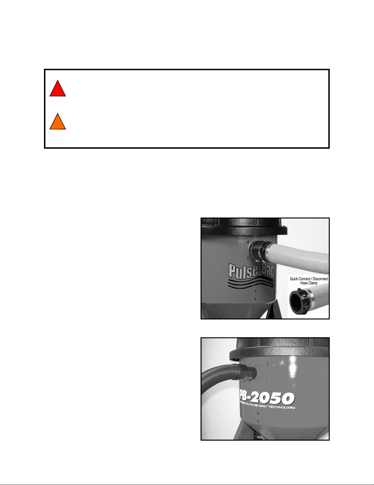
The PB-2050 and PB-2150 are equipped with either a 2” or 3” inlet respectively for use with a 2” or 3”
hose. A properly sealed end-connection is required at the end of the hose when used with manufacturing machinery or surface preparation equipment like floor grinders. The PB-2050 and PB-2150 require a
properly grounded 110 volt or 220 Volt AC, 50/60 Hz power supply to operate properly. If the PB-2050
or PB-2150 are operated from a portable generator, the generator must be equipped with an earth
ground. Generator needs to generate 20 amps for sufficient power.
Figure 1. PB-2150 Inlet
Follow the directions below when starting
and operating the PB-2050 or PB-2150.
1. Connect the proper suction hose to the PB-2050 or
PB-2150 dust port inlet (See Figure 1.) Three inch
for the PB-2150 and a two inch (See Figure 2.) for
the PB-2050.
2. Check the power cord to insure it is in good working condition and plug it into the proper power out-
let. ( see specifications for proper extension
cord use on page 6 of this manual.).
3. Check and ensure that the dust valve on the upper
tank is in the “CLOSED” position.
4. Turn the switch to the “on” position, the dust collector should begin to operate and the switch should
illuminate.
5. Check to see if the dust collector’s hose is connected properly to the device to be operated with
the dust collector.
Figure 2. PB-2050 Inlet
9
Page 10
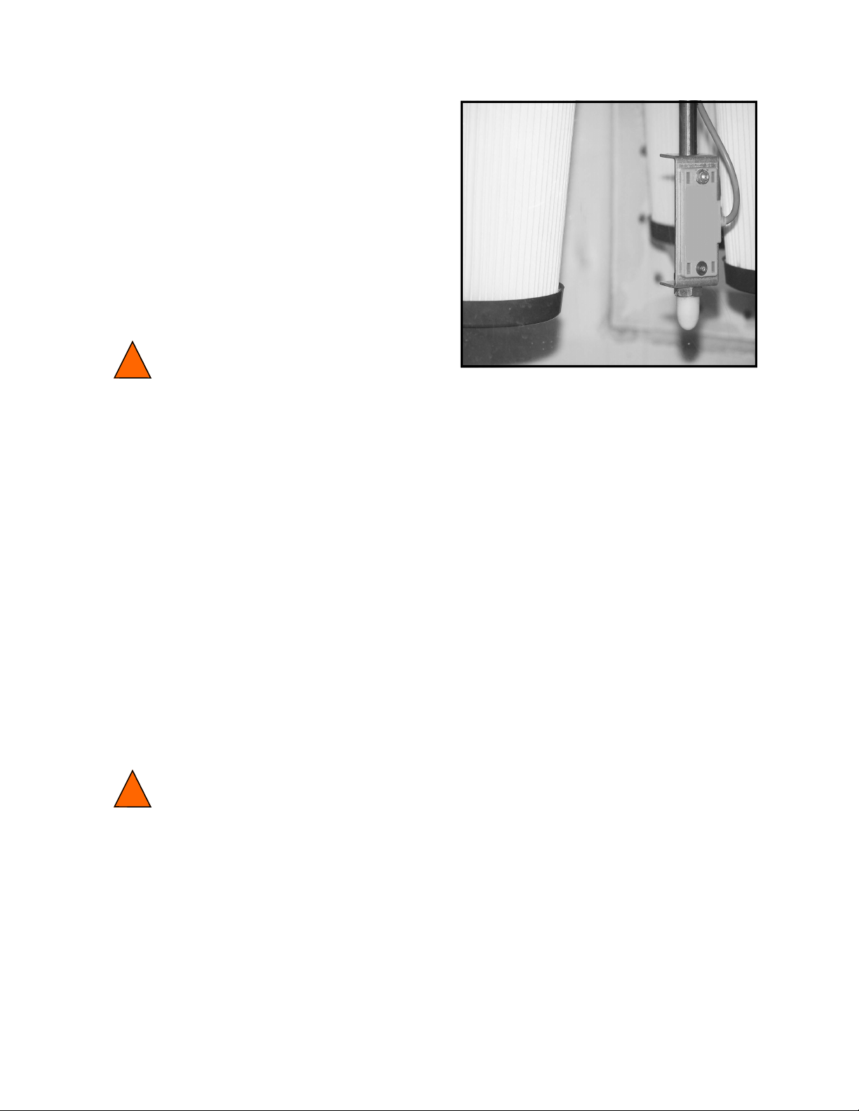
EXCLUSIVE TCS SYSTEM
(TANK CAPACITY SENSOR)
The PB-2050 and PB-2150 dust collectors
are equipped with CDCLarue exclusive Tank
Capacity Sensor (TCS ). The TCS™ system
is designed to prevent the vacuum from
over filling the upper collection chamber;
thereby reducing the risk of damage to the
filters and vacuum motor components.
Warning:
After signaling to the operator with a visual and audible alarm, the TCS system will
automatically turn the vacuum motor off, the vacuum motor can restart automatically
when the dust collectors TCS system is cleared of debris. This restart can cause the
operator to be surprised, possibly causing the operator to be startled and possibly injuring him or herself. Turning the dust collector’s power switch to the off position will
silence the audible alarm and extinguish the visual alarm, and ensure that the vacuum
motor will not restart until the power switch is returned to the on position.
1. The dust collector front bezel is equipped with a Red Light Emitting Diode (LED) indicator along
with an auditable alarm. These two components when lit or sounded notifies the operator that the
TCS sensor has detected a full tank and will turn the dust collector’s vacuum motor off if not emptied
in a timely manner.
2. Once the TCS system has turned the vacuum motor off, the vacuum motor will not restart unless the
tank is emptied or the sensor is cleared. Always check to see if the power switch is illuminated, if
illuminated this indicates that the sensor has the vacuum motor turned off and the PB-2050 or PB2150 is operating properly.
3. The audible alarm will continue to sound off until the sensor is cleared or the dust collector’s power
switch is turned to the off position.
Warning:
Dumping debris when using the Bagger:
When using the PB-2050 or PB-2150 with the bagging attachment, the operator must
insure that the butterfly dump valve is completely closed and sealed anytime the unit is
in operation. If the dump valve is left open or not sealed shut it will reduce the pressure
inside the upper collection tank. The operator can still dump the upper tank into the
bag while continuing to operate the unit in a normal manner as long as the valve is
closed once the main tank has been emptied. Do not leave the butterfly dump valve
open after dumping debris, close it immediately to maintain peak performance.
10
Page 11
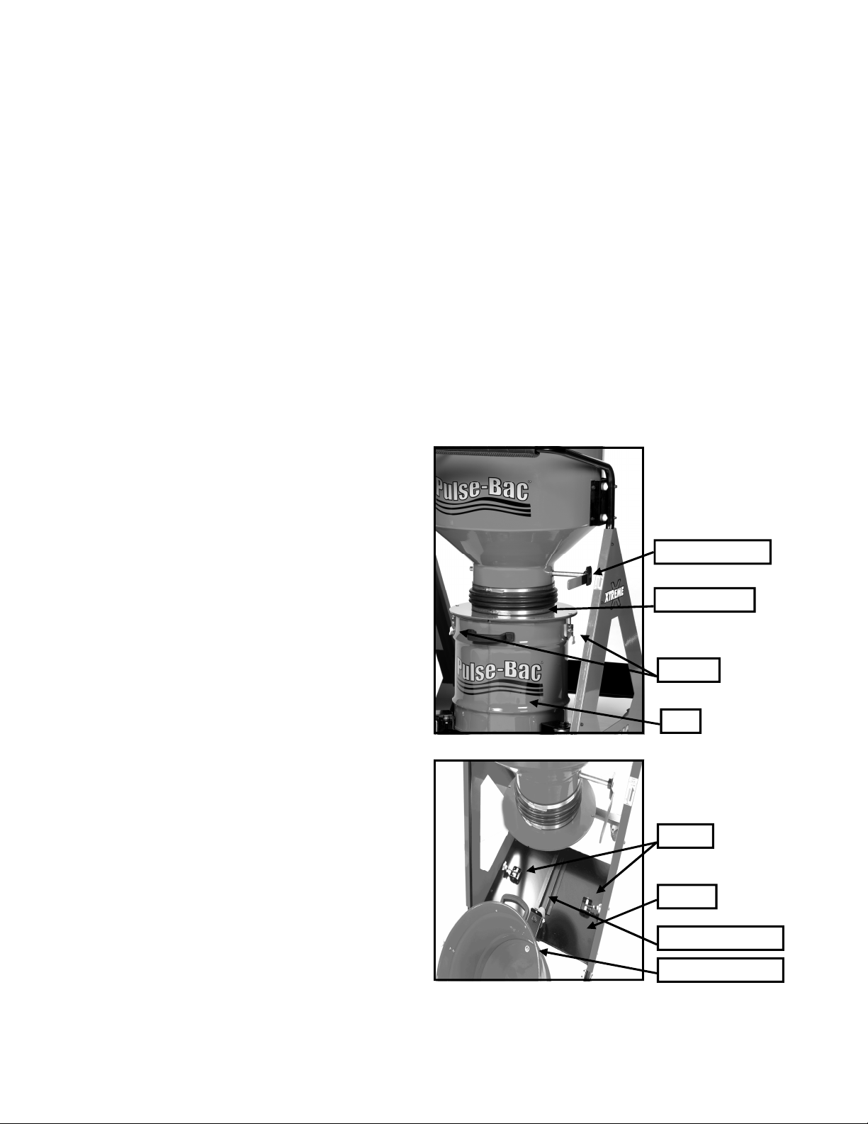
Emptying the dust collector’s removable collection tank:
The PB–2050 and PB-2150 utilizes a unique butterfly valve that separates the upper
tank from the lower 8 gal. removable tank or bag. The valve can be opened and closed
with the dust valve handle shown in (figure 1.).
The butterfly valve allows the PB-2050 and PB-2150 to collect dust and debris in the
upper collection chamber without it falling into the lower removable tank. Once the upper tank is filled, open the valve and dump the debris into the bottom 8 gal. removable
tank or bag, then close and seal the valve. Now the removable tank or bag can be removed and the dust discarded while the machine is still in operation. You do not have
to turn off or stop production when empting and discarding dust and debris.
Collecting dust in the eight (8) gal. removable Tank:
1. Pull latches upward to loosen them from drum
attachment, do not totally unlatch the 8 gal.
tank from the drum attachment at this time.
2. Turn the dust valve handle to the “OPEN”
position and hold it in that position to
allow the dust to fall and settle in the
bottom of the 8 gal. removable tank or bag.
3. Turn the dust valve handle to the “Close”
position to close the valve.
.
4. Turn the knobs on base platform counter
clockwise to loosen, then pull them
to the right, now fully unlatch the two
latches on the tank from the drum attachment.
The tank should now be released from the
cart, roll the tank off the platform to
unload and discard debris.
5. After unloading the tank, place a new bag in
the tank (optional) and roll the cart back onto
the platform, use the guide wheel bracket so
that the latches on the side of the tank align
with the two latch holes on the drum attachment, then latch the tank.
6. Move the knobs over to the right so that they
align to the slots on the tank and then tighten
the knobs to secure the tank to the cart and
platform.
Figure 1.
Dust Valve Handle
Drum Attachment
Latches
Tank
Knobs
Platform
Guide Wheel Bracket
11
8 gal. tank assembly
Page 12
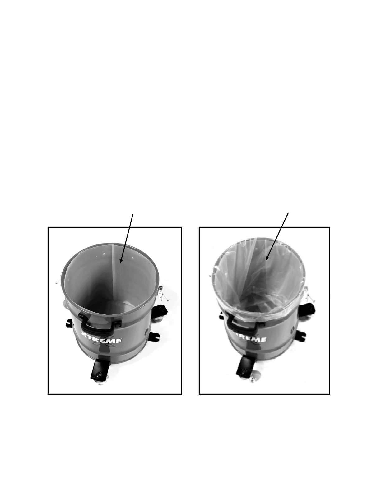
Unloading the Polyethylene Bag from the Collection Tank:
The eight (8) gallon tank has the option of using a six (6) mil. polyethylene bag to
collect dust and debris. This option requires the use of a polyethylene bag and a
nylon liner. The bag fits down inside the liner, and the liner fits down inside the tank
to facilitate easy removal of the dust and debris collected in the bag. After filling the
bag, remove the dust filled bag and install a new bag inside the tank, place the bag
inside the tank so that the bottom of the bag touches the bottom of the tank and
then fold the remaining top part of the polyethylene bag over the rim of the
collection tank as shown in the figure 2..
This procedure can be accomplished while the vacuum continues to operate and
collect dust in the upper chamber, an exclusive feature in both the PB-2050 and
PB-2150 CDCLarue dust collectors. The PB-2050 and PB-2150 are equipped with
CDCLarue exclusive Tank Capacity Sensor (TCS™) which will keep the upper tank
from over filling while the operator empties the lower removable tank to dispose of
the dust and debris collected inside the tank or bag.
Nylon Liner Polyethylene Bag inside
the Nylon liner.
Figure 1. Figure 2.
Figure 1 shows the 8 Gal. Tank with liner inside, and
figure 2 shows the Six mill. Polyethylene bag placed
over the liner
12
Page 13
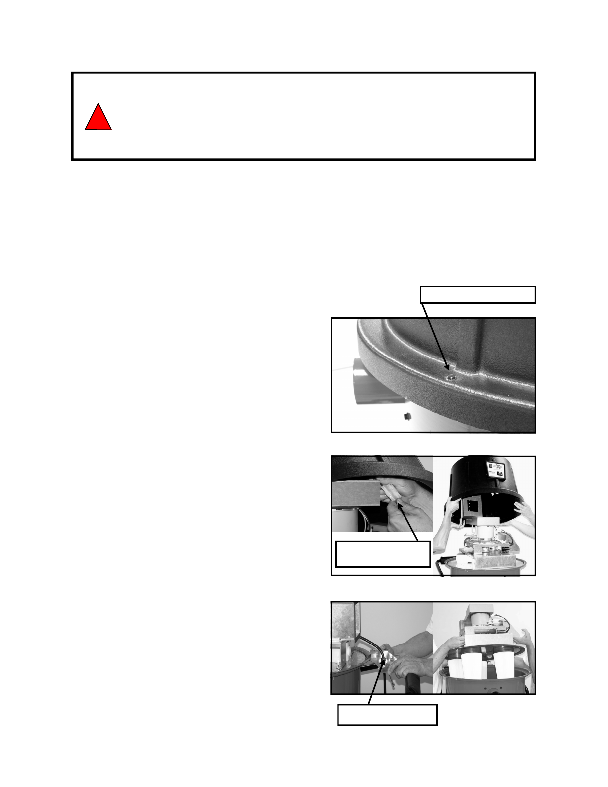
1. Always turn the unit off and disconnect the power by
un-plugging the power cord from the power outlet
WARNING
before removing the top cover.
2. You should be a qualified electrician to perform maintenance on any electrical components.
The PB-2150 is equipped with CDCLarue™ Pulse-Bac® Automatic Self-Cleaning
Technology, all filters are cleaned using vacuum and ambient air, no compressors,
blowers or shakers are used. This Technology allows the machine to continuously operate without having to stop to flush or clean the filters manually. Filter media is made
from a P.T.F.E. coated 100% Spun bond Polyester material. This material increases
the durability and longevity of the equipment.
Filter Replacement:
Figure 1.
Four # 10-32 X 3/4”,
1
. Turn off the dust collector and unplug the
power cord.
2 Locate the 4, 10 X 32 X 3/4”, Hex bolts
that hold the top cover onto the tank and
unscrew them. (See Figure 1.)
3. Disconnect the power switch and the
electrical box connection and remove the
Figure 2.
top cover. (See figure 2.)
4. Locate the 4 ea. 1/4 X 20 Lock nuts that
securely hold the base plate assembly
to the tank and unscrew them.
5. Remove the two bolts, #10/32 X1/2” Hex
Switch/Electrical Box
Connection
bolts holding the power cord bracket on the
tank and remove the bracket. If your unit is
Figure 3.
equipped with an electrical terminal strip,
disconnect the incoming wires before
removing the main base plate to reveal
filters. (See figure 3.)
13
Power Cord Bracket
Page 14
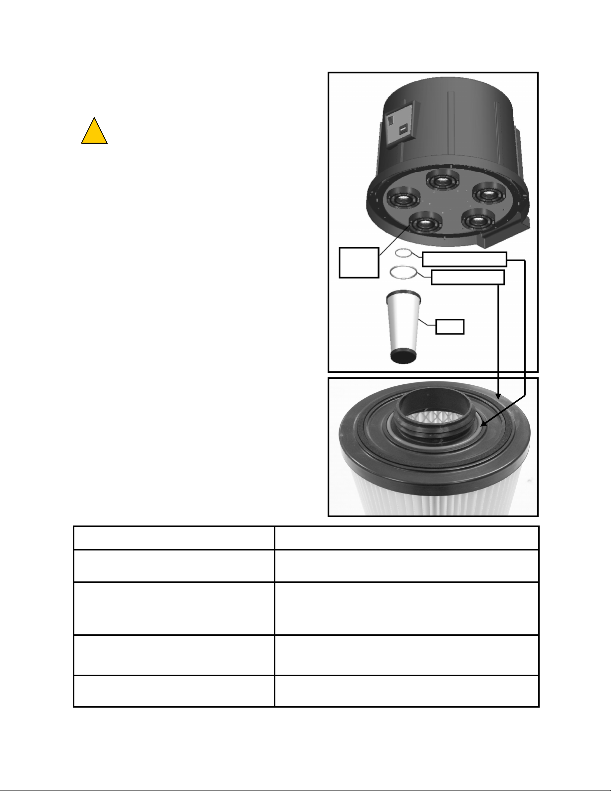
Filter Installation:
CAUTION:
DO NOT LOSE
the O-ring and or
the foam seal on the filters.
1. If not already installed, install the O-Ring
(P/N # 401979) on to the O-Ring groove at
the top of the twist on filter as shown in
figure 2.
2.
If not already installed, install the foam dust
Filter
Receiver
ring (P/N # 403242) into the outer groove of
the filter. **
from accumulating between the top of the filter
and the filter receiver, it is not a seal.
NOTE: The dust ring prevents dust
3. Check to ensure that the filter receiver
is clean and void of any dust or foreign
material before twisting your filter into
Figure 1.
place
4. Insert the filter into the filter receiver and
twist in at a clockwise direction until the
filter touches the base, then turn the filter
one quarter turn to tightly secure it.
O-Ring Seal
Foam Dust Ring
Filter
Trouble Shooting:
Trouble: Remedy:
1. No power indicator.
2. Low Suction and low CFM.
3. Dust exiting motor exhaust port.
4. Motor not running, no suction.
Check for inappropriate power source.
Check power cord connection.
Check to see if inlet & suction hose connection is sealed.
Check to see if Tank and Base are properly aligned & Sealed.
Check to see that dump is completely closed.
Check for improper filter assembly and damaged filters (refer to
Filter removal and re-installation).
Check for blown fuse and or loose electrical connections.
14
Figure 2.
Page 15

CDCLarue 5 / 3 Channel Timer
PCB Revision D
Functional Description
Overview:
The 5/3 Channel Timer circuit design supports several different operating modes –
each of these modes are described in subsequent sections. At the heart of the design
is a microcontroller which handles all of the processing. Upon initial power-up, the microcontroller reads the settings for the Duration & Cycle Adjust Timers and determines
if board supports 3 or 5 channels. Once this information is determine, the Cycle Timer
begins its countdown, once it expires, Solenoid #1 is activated and the Duration Timer
begins its countdown. Upon expiration of the Duration Timer, Solenoid #1 is deactivated. Prior to activating the next Solenoid, the microcontroller inserts a 5 second
pause to allow the pressure in the tank to fully recover. Solenoid #2 is then activated
for specified duration, followed by another 5 second recovery period. This sequence
repeats itself until the last Solenoid (either #3 or #5) has been activated, which completes the cycle. The Cycle Timer is then reloaded and the countdown begins once
again.
Fixed vs. Variable Duration:
The ON duration of the Solenoids is either Fixed or Variable depending on the selected
operating mode. The operating mode is determined by the R16. When R16 is installed, the unit operates in Variable Duration Mode, which has a range of 0.1 to 1 seconds (in 5 millisecond steps). When R16 is removed, the Duration is fixed.
Cycle Duration:
The Cycle Duration has a range from 5 to 105 Seconds (in 200 millisecond steps).
The actual time is determined by a potentiometer setting on the board.
3ch vs. 5ch Selection:
R14 determines whether the unit operates in 3ch or 5ch Mode. When R14 is installed,
the unit operates in 5ch mode. When R14 is removed, the unit operates in 3ch mode.
110V vs. 220V Selection:
Resistors R110A & B and R220 configure whether the unit operates with 110V or 220V
input. For 110V operation, R110A & R110B should be installed (R220 must not be installed). For 220V operation, R220 should be installed (R110A & R110B must not be
installed). These appropriate resistor configuration must be in the appropriate position
prior to power the board.
12Vdc Auxiliary Output:
The Auxiliary 12Vdc output will provide approximately 200ma@12Vdc.
Sensor Support Circuit:
The 12Vdc Auxiliary Output above may be used to power an external (sensor) circuit,
which may in turn drive an on-board relay circuit. The terminal like labeled “SOUT”,
may be connect to the sensor’s output – this is actually an input (0 to 12Vdc), which is
active high (input voltage from 3 to 12Vdc). The state of this input drives an output,
RLY, which is a low side relay driver. This output can sink up to 200ma of current at
12Vdc.
15
Page 16
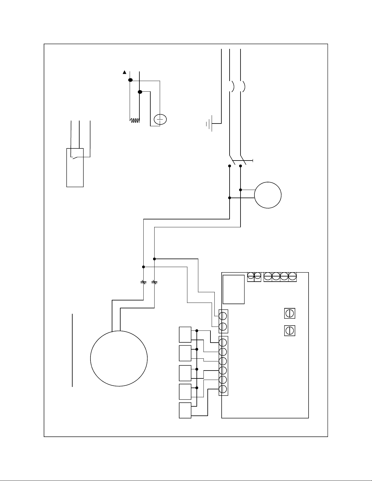
10/06/08
+12V
RLY
Equip. Ground
L
L
1
2
PB-2050 / PB-2150 Block Diagram
F
F
1
2
20 amp
20 amp
+12V
GND
S
OUT
Tank
Full
LED
Bn
Bu
Bk
K
12 VDC
1 coil
DPDT SW 1
Tank Sen-
Hour
Meter
With Tank Sensor
S OUT
RLY
GND
12V
12V
GND
K
Transformer
1
PB-2150 Circuit Shown
S
1
M
S
2
L
1
L
2
Solenoid Connec-
C 1 2 3 4 5
Duration
Cycle
1
S
3
S
4
S
5
PCB
16
Copyright © CDCLarue Industries. 2009
Page 17

Servicing The PB-2050 and PB-2150:
With regular use the dust collector will at some point require repair of critical components from time to
time. This section of your manual will provide information for a qualified technician to make repairs to the
dust collector when required. Most repairs to the dust collector can be made at your facility if the technician making the repairs is trained in electrical and mechanical theory. If you are not qualified to repair
the dust collector you can contact CDCLarue™ customer services department and have the unit returned to CDCLarue or one of CDCLarue authorized service centers for repair. If you or someone you
know are qualified and need additional assistance in the repair of the dust collector, you can contact
CDCLarue service department and a qualified technician will help you to complete the repair.
CDCLarue recommends that any repairs made to the valve systems in your dust collector either be
made by CDCLarue or a technician that is qualified in the theory and repair of electro mechanical equipment.
Danger:
Attempting to repair any electro-mechanical equipment without proper knowledge of the theory
of electricity and mechanics can be detrimental to your health and could cause death or serious
injuries. You should not attempt any of the following repairs without being qualified in electrical
and mechanical repair theory.
If you or someone you have retained plan to make repairs on your dust collector you will need at
minimum the following tools and test equipment;
Volt ohm meter, digital or analog, Phillips screw driver #4 & #3, needle nose pliers,
5/16 “ nut driver, 3/8” end wrench, and 1/8” X 2” slot screwdriver.
Motor Assembly Replacement:
To replace the motor assembly on a PB-2050 and PB-2150 follow the instruction below, each unit is
similar in design, requiring little or no difference between units to remove the motor assembly and replace it with a new motor assembly. Motor assemblies can be ordered from CDCLarue™ by contacting
Customer Service. Have your serial number and model number available when ordering.
1. Disconnect the dust collector from the electrical power source.
2. Loosen the hood cover by removing the four 10-32 X 3/4” Hex bolts holding it to
the base plate. (See Figure 1. Page 13).
3. Lift the hood and disconnect the wiring to the power switch, the TCS™ alarm and
the alarm LED by disconnecting the Molex connectors which connects the wiring
between the main frame and hood of the dust collector. Be sure to do this before
attempting to completely remove the hood.
4. Disconnect the wiring to the motor by unplugging the motor’s Molex power
connector.
5. Locate the two 3/8” lock nuts inside the exhaust duct work (Figure 1. Page 20) and
remove both nuts and the motor fresh air inlet duct.
6. Locate the 4 10/32 screws holding the final exhaust duck work and remove them.
17
Page 18

Motor Assembly Removal Continued:
7. Remove the final exhaust duct work by sliding it forward and off of the motor horn.
8. Remove the six 10/32 lock nuts securing the motor O-Ring seal,
(See Figure 1. Page 21).
9. Remove the three 5/16” flange nuts securing the motor to the main frame of the
base plate and remove the motor from the unit.
10. To replace the new motor, reverse the previous steps, making sure to properly fit
the O-Ring in place to insure a proper seal of the motors intake. (See Figure 1.
Page 21)
Printed Circuit Board Replacement:
1. Disconnect the dust collector from the electrical power source.
2. Loosen the hood cover by removing the four 10-32 X 3/4” Hex bolts holding it to
the base plate. (See Figure 1. Page 13).
3. Lift the hood and disconnect the wiring to the power switch, the TCS™ alarm and
the alarm LED by disconnecting the Molex connectors which connects the wiring
between the main frame and hood of the dust collector, before removing the hood.
4. Locate the four 8/32 x 1/2” screws holding the printed circuit board (PCB) to the
electrical assembly and remove them and let the board float free.
5. Disconnect the eight / six, depending on the model (8) for the PB-2150 and (6) for
the PB-2050, 18 gage solenoid control wires from the PCB. at TB-1 (See Block
Diagram. Page 16).
6. Replace the PCB by reversing the removal directions. The 18 gage wires that connect power to the PCB and the solenoids must be replaced in the proper order for
the dust collector to perform correctly. ( From Right to left facing the mounted PCB
the color code for the 2050 should be ( Blk, Wht, Wht, Gn, Red, and Blk ) and for
the 2150, Right to Left ( Blk, Blk, Wht, Gn, Red, Blk, Blue and Brn ). If you require
technical support to complete the PCB Replacement contact CDCLarue customer
service.
18
Page 19

Servicing the PB-2050 and PB-2150 Continued:
Replacing Valve Solenoids:
1. Before replacing any or all of the solenoids, you must first determine which if any solenoid is
defective. You can determine if a solenoid is defective as follows;
2. Disconnect the dust collector from the electrical power source.
3. Loosen the hood cover by removing the four 10-32 X 3/4” Hex bolts holding it to
the base plate. (See Figure # 1) on page # 13.
4. Lift the hood and disconnect the wiring to the power switch, CCS alarm and alarm LED by
disconnecting the Molex connectors which connects the wiring between the main frame and
hood of the dust collector, before removing the hood.
5. Locate the printed circuit board in the units electrical assembly. Turn to page #16
for a depiction of the wiring block diagram for the solenoids. (Block Diagram) on
page 16.
6 You will need to use your volt ohm meter to determine which if any of the solenoids
is defective. Set your VOM to ohms using a scale of 200 ohms or less. Be sure to
zero your meter before taking your readings.
7. Turn to page 16 of this manual for the location of these test points on the printed circuit
board.
8. Connect your VOM negative test lead to the common point on the solenoid connection block TB1
on the printed circuit board marked ( SC ) or solenoid common. One by one place your positive
lead on each solenoid connection 1 thru 5 or 1 thru 3 for the for the model PB-2050. Each solenoid
should read approximately 84 ohms if the solenoid is good. Solenoids reading “infinity” is a signal
that the solenoid is open and will require replacing.
9. If you have a bad solenoid, you will need to remove the motor, electrical assembly and exhaust
plenum to gain access to the solenoids. You can determine which solenoid to replace by noting
the color of the wire when taking readings from the solenoid connection block. TB 1 on the PCB.
You will need to remove the solenoid plenum housing to gain access to the defective solenoid.
Remove the four (4) 5/16” flange nuts holding the housing to the main base plate,
10. Once you determine which solenoid to replace, disconnect the solenoid from the valve stem by
removing the retaining clip on the retaining pin then remove the retaining pin to release the solenoid
plunger from the valve stem. Do not use the old solenoid plunger or remove the valve to replace the
bad solenoid.
11. Remove the solenoid control wires by removing the quick connect connectors and remove the four
Phillips screws holding the solenoid to the solenoid mounting plate by using a small #4 Phillips
screw driver.
12. Replace the bad solenoid by reversing the above directions used to remove the solenoid.
13, When installing the new solenoid make sure you use lock tight on the Phillips screws
holding the solenoid to the solenoid mounting plate. If you do not lock tight the screws
holding the Solenoid to the solenoid mounting plate they may come loose and go through
the motor fan causing irreversible damage.
19
Page 20
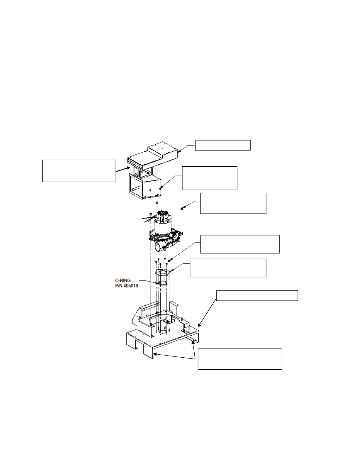
Servicing The PB-2050 and PB-2150 Continued:
Motor replacement diagram:
The diagram below provides an isometric drawing of the motor mounting properties for
the PB-2050 and PB-2150. Using this drawing and the instructions on pages 18 and 19
the motor can be removed and replaced correctly.
Duct Assembly
2 each, 3/8” Lock Nuts
Located inside duck work
4 X Screw, # 10-32
P/N # 401055
3 X Nut, 5/16-18, FLGD
P/N # 405033
Figure 1.
Motor Assembly
6 X Nut, #10-32, NYLOCK
P/N # 401052
Plate, Motor / O-Ring Seal
P/N # 403776
Solenoid plenum housing
4 ea. 5/16” flange nuts holding
plenum housing.
20
Page 21

Contact Information:
CDCLarue Industries, Inc.
9384 Ridgeview St.
Tulsa, OK 74131
PH: 918.216.6100
FX: 918.216.6199
TF: 866.954.9700
Email: [email protected]
URL : www.cdclarue.com
Customer Service hours of operation: Mon—Fri. 8-5 CST
NOTES:
21
Page 22

NOTES:
22
Page 23

Limited Warranty
Pursuant to the specific terms and conditions set forth herein, CDCLarue Industries, Inc. (“CDCLarue”) warrants all products manufactured by CDCLarue™ for a period of one (1) year from any defects in materials and workmanship arising under normal usage and care. Components manufactures offer separate warranty periods. The
aforesaid warranty shall extend only to the original purchaser of the product and all
CDCLarue Distributors based on the original date of purchase, but under no circumstances shall the warranty extend past thirteen (13) months from CDCLarue original
shipment date, regardless of to whom the shipment was sent or when the purchaser
purchased the product. The original date of purchase will be the date indicated on a
bill of sale or receipt.
The purchaser’s remedies under the aforesaid warranty and CDCLarue total obligation under the aforesaid warranty is limited to repair or replacement of any and all
parts or components covered under this limited warranty at the sole discretion of
CDCLarue. The product or products must be returned to CDCLarue place of business,
along with a copy of the bill of sale or receipt indicating the original date of purchase,
and all freight costs associated with the return of the product or products to CDCLarue
for repair or replacement and subsequent freight costs associated with the return of the
product or products to the purchaser will be the sole responsibility of the purchaser. In
the event that the original date of purchase cannot be determined by a bill of sale or
receipt, then the original shipment date according to the records of CDCLarue shall be
used as the original date of purchase. This limited warranty is not transferable or assignable. This limited warranty shall not apply if the product or products have been
abused, misused, altered or damaged by purchaser or a third party. IN NO EVENT
WILL CDCLARUE BE LIABLE FOR ANY DIRECT, INDIRECT, CONSEQUENTIAL,
INCIDENTAL, SPECIAL, PUNITIVE OR OTHER DAMAGES OR FOR ANY CONTINGENT LIABILITY ARISING OUT OF THE FAILURE OF OR USE OF ANY
CDCLARUE PRODUCT, INCLUDING BUT NOT LIMITED TO LOST PROFITS AND/
OR LOSS OF INCOME, WHETHER OR NOT CDCLARUE HAS BEEN ADVISED OF
THE POSSIBILITY OF SUCH DAMAGE, AND REGARDLESS OF WHETHER ANY
REMEDY SET FORTH HEREIN FAILS OF ITS ESSENTIAL PURPOSE.
THE WARRANTIES CONTAINED IN THIS LIMITED WARRANTY ARE IN
LIEU OF ALL OTHER WARRANTIES. EXCEPT AS EXPRESSLY SET FORTH
ABOVE, CDCLARUE EXPRESSLY DISCLAIMS AND NEGATES ALL REPRESENTATIONS OR WARRANTIES, WHETHER EXPRESS OR IMPLIED, IN FACT OR IN
LAW, RELATING TO THE PRODUCTS (INCLUDING WITHOUT LIMITATION
(A) ANY IMPLIED OR EXPRESS WARRANTY OF MERCHANTABILITY, (B) ANY
IMPLIED OR EXPRESS WARRANTY OF FITNESS FOR ANY PURPOSE, (C) ANY
IMPLIED OR EXPRESS WARRANTY OF CONFORMITY TO MODELS OR SAMPLES OF MATERIALS, (D) ANY IMPLIED OR EXPRESS WARRANTY REGARDING THE CONDITION OF THE PRODUCTS AND (E) ANY IMPLIED WARRANTY
ARISING FROM COURSE OF PERFORMANCE, COURSE OF DEALING OR USAGE OF TRADE).
23
Page 24

9384 Ridgeview Street Tulsa, OK 74131
PH: (866) 954-9700 Fax: (918) 216-6199
Email: [email protected] URL: www.cdclarue.com
 Loading...