

Page 1
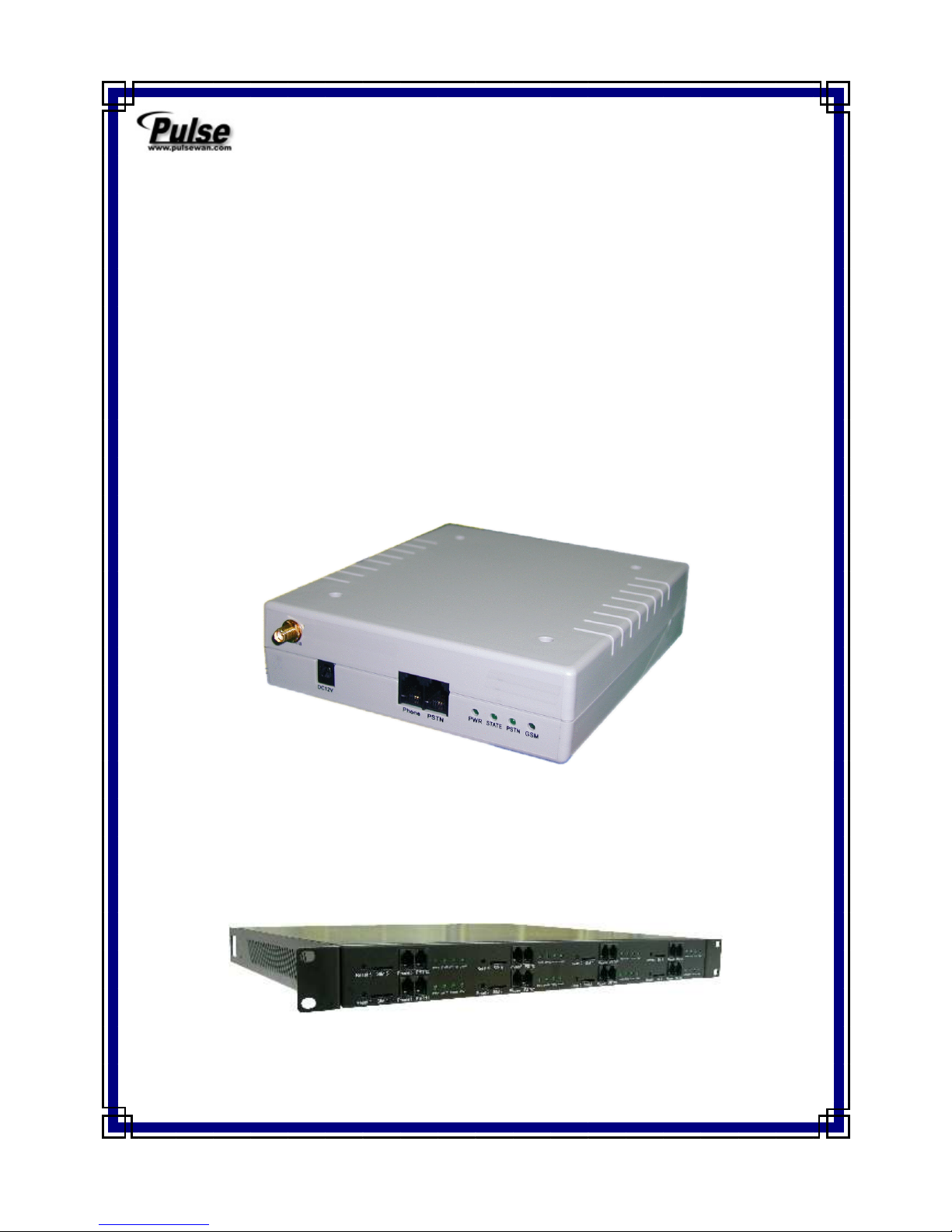
GSM Gateway
Operation Manual
1 port
4 ports / 8 ports
Page 2

§ INDEX §
1. Preface......................................................................................................................... 1
2. Function Interpretation................................................................................................ 1
3. Parts Of Equipment..................................................................................................... 2
4. Dimension Drawing .................................................................................................... 3
5. Demonstration on Double Sides of Equipment .......................................................... 4
6. Install Line Connections ............................................................................................. 6
7. Set the Allow-to-Dial Code ........................................................................................ 7
8. Code Conversion Setting ............................................................................................ 8
9. Cancel Code-Conversion ............................................................................................ 8
10. Set Parameter ............................................................................................................ 8
(1)Set GSM dial-out code amount .............................................................................. 8
(2)Polarity reversing function ..................................................................................... 8
(3)Definition of DTMF reversing signal ..................................................................... 9
(4)Limit of communicating time ................................................................................. 9
(5)GSM function of dialing out the prompt tone ........................................................ 9
(6)When not connecting to Telephone Office line, GSM will provide the forced
dial-out function .......................................................................................................... 9
(7)Set up GSM extra dialing local code .................................................................... 10
(8)Voice volume modulation .................................................................................... 10
(9)Restore default setting .......................................................................................... 10
(10)Set up extra dialing local-code to PSTN ............................................................ 11
(11)GSM simulated echo-bell-sound function.......................................................... 11
(12)GSM isn’t ready, call will be forced to dial out from PSTN.............................. 11
11.Setting of Specific Call-Transfer *Dual band Only,Tri band and SMS version
don’t have this feature................................................................................................... 12
(1)PSTN TO GSM .................................................................................................... 12
(2)GSM TO PSTN .................................................................................................... 12
(3)GSM free transfer setup........................................................................................ 13
12. Short Code Setting .................................................................................................. 14
13. Call-Transfer Restriction Setting ............................................................................ 15
14. Echo Cancel Function ............................................................................................. 15
15. Q&A........................................................................................................................ 16
16 Specification ............................................................................................................ 18
Page 3

Operation Manual 1
1. Preface
Congratulations! You have selected the remarkable product “ GSM Gateway” by your
sharp and intellectual judgment. This product will provide you the best wire and wireless
communication services. Before using this product, you have to read over this Operation Manual,
letting this product serve you with its full functions, to satisfy your ideal desire and enjoy
yourself in the wire and wireless communication applied in daily lives. The product is under our
delicate design, which has fulfilled the ideal way of communications expressed on the slogan of
“making wireless to wire” versus “making wire to wireless”. It can save your communication
expense and bring you an unpredictable effort using this product.
2. Function Interpretation
(1) Conversion of wire & wireless communication
We can use GSM Gateway to apply conventional telephone set replacing cell phone to
perform sending and receiving phone calls.
(2) Auto-select economic route
From various settings, will determine the calls connected through local PSTN Line or GSM
on accordance of call numbers dialed therein, which can save phone-call fee as a favorable
benefit.
(3) Through the connection towards local PSTN line, the phone calls will proceed with
code-transfer dialing process. For example, when you dial “002”, will transfer it to “006”
and transmit the calls through the other fixed communication network systems.
(4) Voice volume modulating system
In order to cooperate with different application environment, the Wizard is capable to
modulate the voice volume of phone.
(5)MVPN Function
Provide MVPN routing according to the prefix of MVPN number for GSM carrier.
Page 4
Operation Manual 2
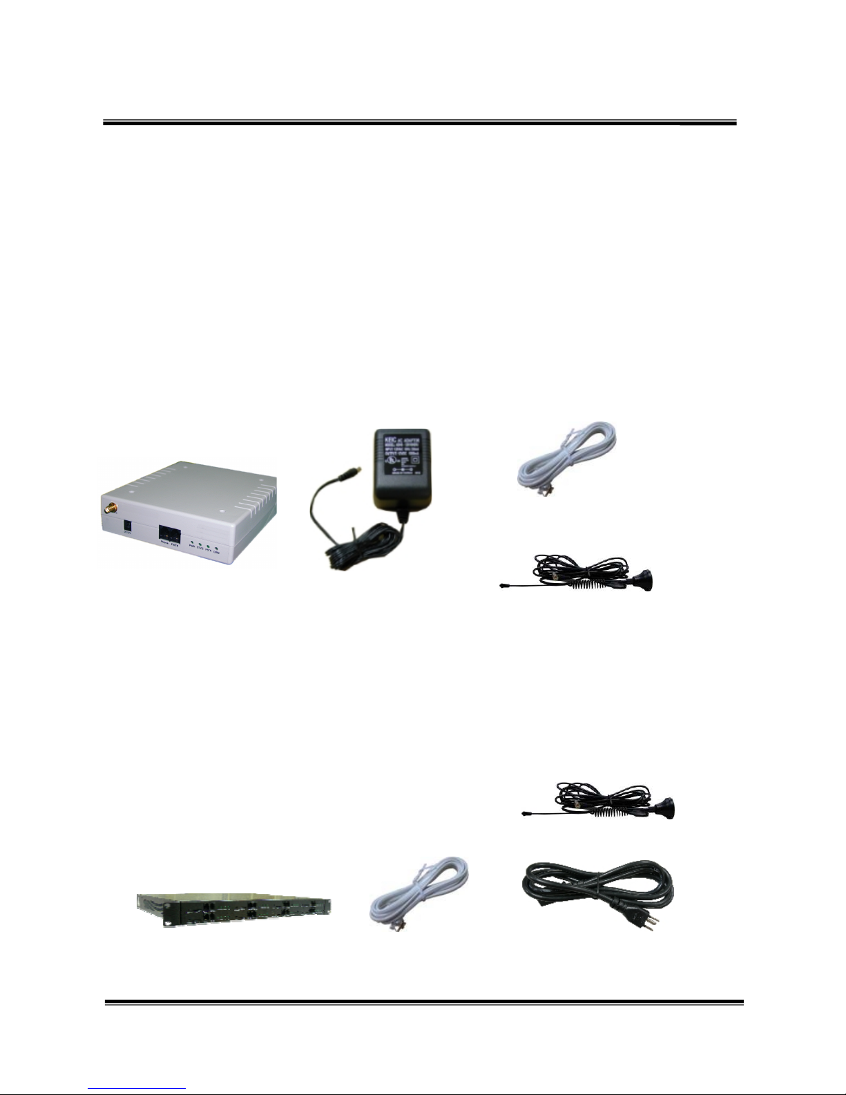
3. Parts Of Equipment
After opening the package, please check whether all parts attached to Wizard are
provided in the package. If there is any missing, please query the sales agent promptly to
supplement for the insufficient parts. The parts on the list are specified below:
3.1 1 port
(1) The Main Device
(2) Transformer AC-DC (110V AC – 12V DC) or (220V AC – 12V DC)
(3) Phone connecting Line
(4) Antenna
(5) This Operation Manual
3.2 4 ports / 8 ports
(1) The Main Device
(2) Phone connecting Line (4 ports 4 lines/8 ports 8 lines)
(3) Antenna (4 ports 1 set/8 ports 2 sets)
(4) Power cord–option European , American , Australian Standard
(5) This Operation Manual
(1)
(2)
(4)
(3)
(1)
(2)
(3)
(4)
Page 5
Operation Manual 3
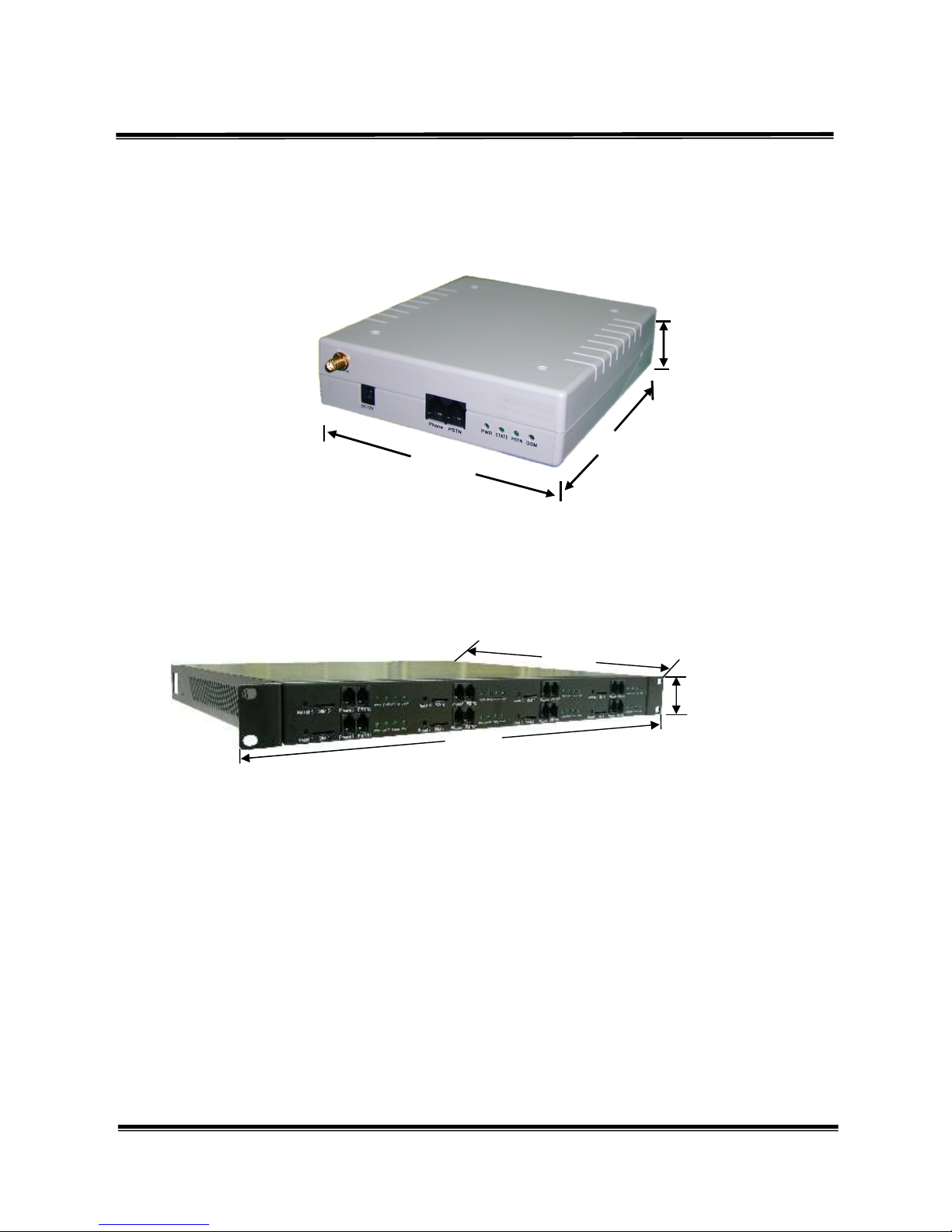
4. Dimension Drawing
4.1 1 port
4.2 4 ports / 8 ports
4.0cm
14.5cm
17.0cm
48cm
4.5cm
38cm
Page 6
Operation Manual 4
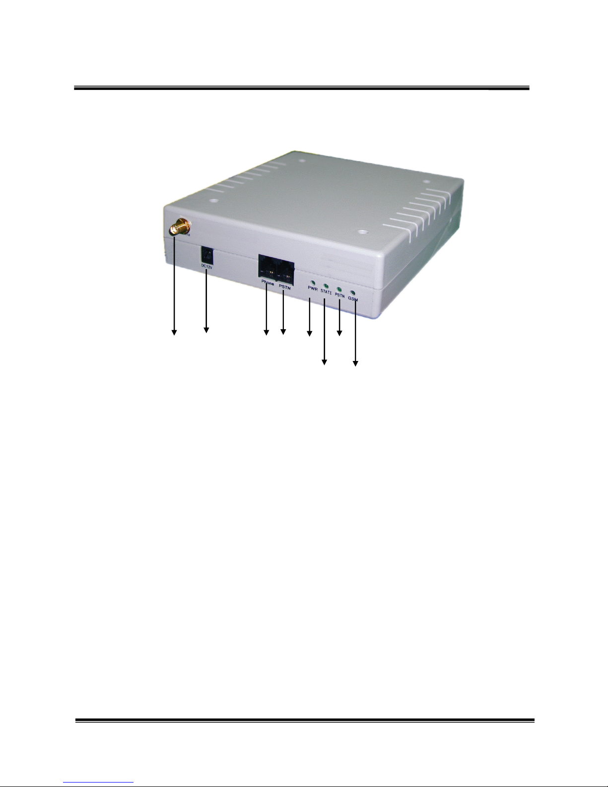
5. Demonstration on Double Sides of Equipment
5.1 1 port
(1) Socket of externally connected antenna.
(2) DC 12V: power input.
(3) PHONE: Telephone/PBX connector; with standard RJ-11 USA type plug, connected to the
phone set or PBX.
(4) PSTN phone jack : Central office line interface, standard RJ11 phone jack.
(5) PWR LED (Power Indicator)
(6) STATE LED :
Slow flashing :during the initialization stage.
Light up: when the phone set is picked up.
Fast flashing: during the GSM line in use.
Flash timing indicates the RSSI(received signal strength indicator), 5 times per second for
the strongest receiving, 1 time per second for the poorest receiving.
(7) PSTN LED : Flashing during the PSTN line in use.
(8) GSM LED : Fast flashing when the GSM channel is available, otherwise, slow flashing.
** Insert the SIM card from the back (take off the slide first)(MT-350 1 port)
** Insert the SIM card in the front(MT-354/358 Quad/Octa Port)
Important:You must off your PIN Code of your SIM Card by your cellular phone
(1) (2) (3) (4) (5) (7)
(6) (8)
Page 7

Operation Manual 5
5.2 4 ports / 8 ports
(1) Reset button: After changed SIM card, please press reset button for 5 seconds.
(2) SIM Card: Please insert SIM card.
(3) PHONE: Telephone/PBX connector; with standard RJ-11 USA type plug, connected to the
phone set or PBX.
(4) PSTN phone jack : Central office line interface, standard RJ11 phone jack.
(5) LEDs
All LEDs indicating function are same as 1 port GSM Gateway
(6) Switch Power: Switch the AC input voltage 110v/220v
(7) Antenna: Connecting with antenna
(8) ON/OFF: The switch of the AC power
(9) Fuse: If power failed, please check the fuse.
(10) AC-In: Connecting with power cord
(1) (2) (3) (4)
(5)
(6) (7)
(8) (9) (10)
Page 8

Operation Manual 6
6. Install Line Connections
6.1 1 port
Wiring Diagram
(1)Take apart your local PSTN connecting line from the phone or PBX, and connect it to the
LINE connecting slut of . If you use to send and receive calls only, then you don’t need to
connect the local PSTN line.
(2)Connect PHONE connecting slut to the inlet side of phoneset or PBX.
(3)Put in transformer power. The DC end connects to DC 12V of , and then the PW lamp on the
front side of should light up.
(4) will proceed with system detection after booting. Please connect the Line and Phone
correctly before energizing it. If problem is found during the system operation, please take
power source off first and process wiring task next.
PBX
Page 9

Operation Manual 7
6.2 4 ports / 8 ports
※※※※There are no any different between 1 port、、、、4 ports and 8 ports, base on
setting.
7. Set the Allow-to-Dial Code
(1)Hold the phone and dial numbers following the order illustrated below:
***#nnnn#: n means the code that allows sending calls out from GSM. Hang up the phone
and the setting is thus completed. When the coding number is altered, follow the above steps
to set up again.
when nnnn is set to ※※※※ **
****
**, it will close the calls-sending function from GSM.
Format: ***# [waiting for confirming tone] (turn setting function on)
nnnn# [waiting for echo tone in responding]
Where nnnn means the allow-to-dial prefix code, which as ***#0937, #0948# are on
behave of 0937- and 0948-; the prefix code is dialed out from GSM.
Default setting =0, all call number starting with code “0” means allow-to-dial code.
Sim
Phone
or PBX
Local PSTN
A
ntenna
Power cord
Page 10

Operation Manual 8
8. Code Conversion Setting
Format: ###* [Waiting for confirming tone] (turn setting function on)
aaaa# [Waiting for echo tone in responding]
bbbb# [Waiting for echo tone in responding]
Where aaaa means original code, bbbb means converted code; the ###*002#006# means
converting prefix codes 002- to 006- automatically.
We have defined this code dialing mechanism outputting through Telephone Office line
system of PSTN. If we want to output through GSM, we can set the first code to “*”, such as
###*002#*006#, which means that will auto-convert prefix codes 002- to 006- and dial out
through GSM.
9. Cancel Code-Conversion
Format: ###* [Waiting for confirming tone] (turn setting function on)
**# [Waiting for echo tone in responding]
is to cancel code conversion function.
10. Set Parameter
(1)Set GSM dial-out code amount
Format: *#** [Waiting for confirming tone]
71aabb#
aa means dial-out number of call digits, bb have to be inputted in exactly identical to aa.
Example: *#**711010#, which means setting dial-out number of call digits = 10. If correct, will
beep up once in response. If not correct, will beep up four times consecutively instead.
Default setting =10
(2)Phone line Polarity reversing function
Format: *#** [Waiting for confirming tone]
510101# is to turn the reversing function off,
510202# is to turn it on (default).
Default setting = 02
Page 11

Operation Manual 9
(3)Definition of DTMF reversing signal
Format: *#** [Waiting for confirming tone]
52aabb#
In some regions or systems, DTMF reversing signals vary and can be defined by this
function:
aa= 11 (* TONE), 12(# TONE), 13(A TONE), 14(B TONE), 15(C TONE),
00(D TONE)
bb needs conforming to aa.
Default setting = 15 (C TONE)
(4)Limit of communicating time
Format: *#** [Waiting for confirming tone]
61aabb#
aa means the communicating time in the unit of min. ( 00-99), and will show alerting sound 30 sec
ahead of disconnect. bb should be identical to aa by input. If setting to “00”, it then means
unrestricted.
Example: *#**610505#, which means that system will send out alert sound at the communicating
time of 4:30, and hang up it at about 4:55. If correct, the will beep up once in response.
If not correct, the then will beep up four times consecutively instead.
Default setting = 00
(5)GSM function of dialing out the prompt tone, means this call is through GSM.
Format: *#** [Waiting for confirming tone]
530101# turn off prompt tone.
530202# turn on prompt tone (default).
Default setting = 02, turn on this function.
(6)When not connecting to Telephone Office line(PSTN), GSM will provide the forced
dial-out function
Format: *#** [Waiting for confirming tone]
550101# turn off function of forced dial-out.
550202# turn on function of forced dial-out (default)
Default setting =02, to turn on this function.
Page 12

Operation Manual 10
(7)Set up GSM extra dialing local code
When both GSM and PSTN dial local code, the difference between them is that GSM has
to extra dial up local code whereas PSTN needs not. This function applies to the condition
that when PSTN has been cut and user dials local phone No., system thus will add in local
code automatically and dial out from GSM.
Format: *#** [Waiting for confirming tone]
63aabb#
aa means code limit. There are still certain restrictions when auto-adding local code, such
as that the service or emergent phone calls need not to add extra code dialing action. This
setting is that when the total phone number length inputted is shorter to the setting value,
then won’t extra dial local code. bb means local code (2~8 digitals), it isn’t contained in
the original code while dialing out through GSM, and will auto-add it in advance.
Example: *#**630604#, if the prefix code isn’t “0” (04), and total code number isn’t less
than 6, then when dialing out form GSM it will dial “04” ahead of the other
code numbers. If correct, the will beep up once in response. If not, the then will
beep up four times consecutively instead.
Default setting =00, to turn off this function.
Note: If it isn’t connecting to PSTN, then the phone won’t dial out through
GSM, in case not setting up this function and not passing through the
checking number of allow-to-dial code.
(8)Voive volume modulation
21 aabb#
aa means voice volume, which varies from 00-04, 00 is the bottom value and 04 is the peak one.
bb should be externally inputted identical to aa.
Example: *#**210404#, it means that the voice volume is set to the maximum value. If correct,
the will beep up once in response. And if not, the then will beep up four times
consecutively instead.
Default setting =04, it means that the maximum voice volume is set up.
(9)Restore default setting
Format: *#** [Waiting for confirming tone]
Page 13

Operation Manual 11
990909#,
the only act needed to follow is to reboot machine.
(10)Set up extra dialing local-code to PSTN
Format: *#** [Waiting for confirming tone]
11aaaaa#
aaaaa means the digitals dialed out with extra codes can extend to 12 digitals.
Example: *#**111805#, it means that if the phone number is dialed out with two prefix digitals
of 02-08 through PSTN, it will automatically dial out 1805 in advance. If correct,
the will beep up once in response. If not correct, the then will beep up four times
consecutively instead.
Default setting: None.
(11)GSM simulated echo-bell-sound function
Format: *#** [Waiting for confirming tone]
57aabb
It’s the function of dialing out phone call from GSM and generates echo-bell-sound before starting
to talk in the phone.
aa means echo-bell-sound time in a unit of 0.1 sec. ( 00-98).
bb needs to be inputted identical to aa. This function will disable if setting up to “00”.
If setting up to “99”, it won’t have time limit on it.
Notice: that this echo function will be halt if there is actual echo sound, reply or voice response
occurred therein.
Default setting =00 (turn off this function).
(12)GSM isn’t ready, call will be forced to dial out from PSTN
Format: *#** [Waiting for confirming tone]
59aabb
While GSM isn’t ready, the function will let the phone forcedly dial out from PSTN.
If aa is set to “01”, it means that the call is not to dial out through PSTN and presented by the tone
signal of busy line.
If aa is set to “02”, it means that the phone call is forced to dial out through PSTN.
bb needs to be inputted identical to aa.
Page 14

Operation Manual 12
Notice: that this echo function will be halt if there is actual echo sound, reply or voicel response
occurred therein.
Default setting = 02 (forced to dial out through PSTN).
11.Setting of Specific Call-Transfer
*Dual band Only,Tri band and SMS version don’t have this feature
(1)PSTN TO GSM
The GSM GATEWAY can receive calls from PSTN and send them out through GSM.
Format: *#** [Waiting for confirming tone]
80nnnn#[Waiting for echo tone in responding]
Where 80 are function codes, nnnn means the call number is to be dialed out.
To cancel this function, press *#**80**#.
Example: *#**800911123456#, represents that PSTN send-in call can be dialed out to
0911123456.
(2)GSM TO PSTN
(2.1)Setup GSM-to-PSTN assigned mode
This machine can receive calls from GSM and dial them out through PSTN.
Format : *#** (Waiting for confirming tone)
81nnnn# [Waiting for echo tone in responding]
Where 81 are function codes, nnnn means the call number is to be dialed out.
To cancel this function, press *#**81**#.
Example: *#**810281112345#, represents that GSM send-in call can be dialed out to
0281112345.
At some circumstances it needs to add “#” in the last digital of PSTN number.
To input it, press “#”, and “*” to certify the input.
Example: *#**810423210287*#, it means dialing out phone call to 0423210287#
(2.2)GSM call-Transfer setting time to PSTN auto response
When GSM phone call is dialed out through PSTN, it doesn’t have the responding signal in
some practical applications and requires to use this function to auto-respond a few seconds
later.
Format: *#** [Waiting for confirming tone]
Page 15

Operation Manual 13
82aabb#[Waiting for echo tone in responding]
Where 82 are function codes, aa represents time delay to auto- respond in the unit of 0.5 sec.
bb should be identical to aa.
Example: *#**821010#, it means that machine will auto-respond after 5 seconds.
Example: *#**820000#, it means that after call is dialed out, it can receive
responding signal only when the other side of call makes corresponding
signal.
Default value: 10 sec later to auto-respond it.
(2.3)DTMF definition of reversed signal
Format: *#** [Waiting for confirming tone]
52aabb#
In some zones or systems, various DTMF reversed signals can be defined by this
function.
aa=11 (* TONE), 12(# TONE), 13(A TONE), 14(B TONE),15(C TONE),
00(D TONE)
bb should be identical to aa.
Default setting =15 (C TONE)
(3)GSM free transfer setup
(3.1)Setup GSM-to-PSTN free mode
Format : *#** (Waiting for confirming tone)
81****#[ Waiting for prompt tone]
Once the GSM-to-PSTN free mode has be set, all the incoming calls from GSM will
be answered and prompt to enter password. If the password is correct, the calling
party can hear the Bi tone, then he/she can dial out using the PSTN line.
To cancel this function, press *#**81**#.
(3.2)GSM-to-PSTN free mode password setup
Format : *#** (Waiting for confirming tone)
83aaaabbbb#[ Waiting for prompt tone]
83 is the function code, aaaa is the password, bbbb should be the same as aaaa.
Example: *#**8312341234# means the calling party needs to enter 1234 for
Page 16

Operation Manual 14
password authentication. Entering password has to be done in 30
seconds. If no password is required, press *#**83**#
Default password : no password
(3.3)Password prompt tone setup
Format : *#** (Waiting for confirming tone)
84aabb#
84 is the function code, bb should be the same as aa
aa=11 (* TONE),12(# TONE), 13(A TONE),14(B TONE),5(C TONE),00(D
TONE),16 No tone
Default value : 15 (C Tone)
▓Remarks
Interpretation of echo-sound
[Command confirmed]: two beeps
[Setting is correct]: single beep
[Setting is error]: four consecutive beeps.
12. Short Code Setting
Allow to setup 100 sets of short code. Once the short code has been set (see function 31
below), user may press 00# ~ 99# for fast dialing. (*0# ~ *9# are also accepted and regards
as *00# ~ *09#). The routing function applies to the setup number rather than the short
code itself.
To enable/disable the short code function :
Format : *#** (wait for confirming tone)
30aabb#
aa : 01 for disable short code function
02 for enable short code function
99 clear all the numbers associated with the short codes
bb : should be the same as aa
To set the number for short code :
Format : *#** (wait for confirming tone)
Page 17

Operation Manual 15
31aabbbbbb#
aa should be 2 digits ranges from 00 to 99 as the short code
bbbbbb : the number to be associated with the short code, max. 15 digits
Notice! : the function cod 99 (reset to factory setting) doesn’t affect the short code
number setting.
13. Call-Transfer Restriction Setting
Allow to setup 10 sets of number which are allowed to do call-transfer from mobile to
PSTN. All calls from other numbers will transfer to phone set.
Restrict function setting
Format : *#** (wait for confirming tone)
36aabb#
aa : 01 means no restriction. All calls from mobile will be transferd to PSTN
02 restrict the numbers set by function 37(see as below)
99 clear all the restriction numbers
bb : should be the same as aa
Default setting : 01, all calls will be transferred.
Restrict number setting
Format : *#** (wait for confirming tone)
37aabbbbbb#
aa should be 2 digits ranges from 00 to 09 as restrict code
bbbbbb : the number to be associated with the restrict code, max. 15 digits
!!Note : the function cod 99 (reset to factory setting) doesn’t affect the restrict code
number setting
14. Echo Cancel Function
*#**20NNNN#
NNNN= 0101
Echo Cancel Enable
Page 18

Operation Manual 16
NNNN= 0202
Echo Cancel Disable
Default: 0202
15. Q&A
Q1: “PWR” lamp doesn’t light up after power on?
A : No power transmitted to power plug, or the transformer is mal-functioned.
Q2: No further vocal sound heard after picking up the phone?
A : Phone line is disconnected or wrong wire connected.
Q3: Why the “Busy Tone” is heard directly wile picking up phone?(Not linked to PSTN)
A : GSM isn’t ready yet, it might occur from the reasons of disconnecting antenna, not able
to receive signals or equipment mal-functioned.
Q4: How to set up allow-to-dial number?
A : Step I: connect a call receiver at phone.
Step II: lift up phone.
Step III: dial ***#, and set up all-to-dial code after hearing “beep” sound, then
press # again to confirm.
If we need to set up more than one allow-to-dial codes, use # to separate them off.
Ex: ***#0910# beep 0920# beep
It means that the allow-to-dial number is set to 0910 and 0920.
Step IV: hang up phone speaker and the setting process is over.
Q5: How to clear up the former setting of allow-to-dial?
A : Each new setting will auto-cover over the former two settings.
Q6: How to quick-sending out codes?
A : Press # after dialing out phone call, it will be sent out immediately.
Page 19

Operation Manual 17
Q7: how many allow-to-dial codes can this machine memorize?
A : 50 sets.
Q8: Can we use to fax or make data preparation?
A : Negative, only can perform tone function exclusively.
Q9: After setting up allow-to-dial code, why we can’t select the allow-to-dial route?
A : (1) Check if line (PSTN) is connected properly.
(2) The allow-to-dial function hasn’t been set up yet, i.e., not to follow the correct setup
procedure processing setup.
(3) This machine derives the line malfunction inspecting ability. If the line is out of
order, it will connect to GSM route in a forced way (have to set up local code in
advance).
Q10: If the has no power on it, and its line connects to PSTN, can it dial out?
A : Yes, it could, yet is confined to dial out by PSTN only.
Q11: Can the phone make inspection on the echo signal of polarity reversal?
A : Yes, it could. When call is dialed out through GSM, the phone will make linear
polarity reversal when it’s called for echo response.
Q12: Does the machine deserve CLID function?
A : Yes, it does. When GSM sends in call signal, it will send the CLID out from phone by
DTMF signal.
Q13: How to compulsorily dial out any number through GSM (VPN)?
A : We can press ’*’ before dialing out, and dial phone number next to it. Finally, press ‘#’
to finish this task.
Page 20

Operation Manual 18
16 Specification
(1) Phone impedance: under DC 1kΩ, AC 600Ω (exclude wire impedance).
(2) Phone signal receiving level: -3dbm~-24dbm.
(3) Phone signal time: 50~100ms.
(4) Phone frequency error: ±1%.
(5) Feed voltage: 48V.
(6) Power converter: Input:230/110 VAC 50/60 Hz 200mA,Output:12VDC,1000mA
(7) GSM specification:
(7.1)GSM Frequency bands: Dual Band EGSM 900 and GSM 1800(GSM Phase 2+)
(7.2)GSM class: Small MS
(7.3)Transmit power:
Class 4(2W) for EGSM 900
Class 1(1W) for GSM 1800
(7.4)SIM card reader: External – connected via interface connector
(7.5)Antenna: 50Ωantenna coaxial connector
(7.6)Temperature range:
Normal operation: -20 to +55℃ ℃
Restricted operation:-25 to ℃ -20 and +55 to 70℃ ℃ ℃
Storage:-40 to +85℃ ℃
 Loading...