

Page 1

Generator
OPERATOR’S MANUAL
Model: PG15KVTWB
www.pulsar-products.com
Page 2

INTRODUCTION
Congratulations on your selection of a this generator. We are certain you will be pleased with your purchase of one of
the finest generators on the market.
We want to help you get the best results from your new generator and to operate it safely. This manual contains all the
information on how to do that; please read it carefully.
As you read this manual, you will find information preceded by a symbol.
That information is intended to help you avoid damage to your generator, other property,
or the environment.
e suggest you read the warranty policy to fully understand its coverage and your responsibilities of ownership.
W
When your generator needs scheduled maintenance, keep in mind your THIS servicing dealer is specially trained in
servicing THIS generators. Your authorized THIS servicing dealer is dedicated to your satisfaction and will
be pleased to answer your questions and concerns.
A FEW WORDS ABOUT SAFETY
Your safety and the safety of others are very important. And using this generator safely is an important responsibility.
To help you make informed decisions about safety, we have provided operating procedures and other information on
labels and in this manual. This information alerts you to potential hazards that could hurt you or others.
Of course, it is not practical or possible to warn you about all the hazards associated with operating or maintaining a
generator. You must use your own good judgement.
You will find important safety information in a variety of forms, including:
Safety Labels on the generator.
Safety Messages preceded by a safety alert symbol and one of three signal words, DANGER, WARNING, or
CAUTION.
Safety Headings such as IMPORTANT SAFETY INFORMATION.
Safety Section such as GENERATOR SAFETY.
Instructions
This entire book is filled with important safety information please read it carefully.
how to use this generator correctly and safely.
1
Page 3

CONTENTS
GENERATOR SAFETY ........................................................................................................................................................ 4
IMPORTANT SAFETY INFORMATION
Operator Responsibility
Carbon Monoxide Hazards .......................................................................................................................................... 4
Electric Shock Hazards ................................................................................................................................................. 4
Fire and Burn Hazards ................................................................................................................................................. 4
Refuel With Care ......................................................................................................................................................... 4
SAFETY LABEL LOCATIONS ............................................................................................................................................... 5
......................................................................................................................................................
CONTROLS & FEATURES ......................................................................................................................................................... 6
ONENT & CONTROL LOCATIONS ............................................................................................................................ 6
COMP
CONTROLS
Fuel Valve Lever ........................................................................................................................................................... 8
Choke Knob ................................................................................................................................................................. 8
Engine Switch ............................................................................................................................................................... 8
Cir
FEATURES
Oil Alert System ........................................................................................................................................................... 9
Ground Terminal
Fue
Volt Meter ................................................................................................................................................................... 9
Hour Meter.................................................................................................................................................................. 9
................................................................................................................................................................................
cuit Breaker ............................................................................................................................................................. 8
..........................................................................................................................................................................................
..................................................................................................................................................................
l Gauge .................................................................................................................................................................. 9
......................................................................................................................................
4
4
8
9
9
BEFORE OPERATIO N
ARE YOU READY TO GET STARTED? ................................................................................................................................ 10
Knowledge
IS YOUR GENERATOR READY TO GO?
Check the Engine ....................................................................................................................................................... 10
Check the Battery ...................................................................................................................................................... 10
........................................................................................................................................................
.........................................................................................................................................................................
............................................................................................................................. 1
10
10
0
OPERATION .............................................................................................................................................................................11
SAFE OPERATING PRECAUTION ..................................................................................................................................... 11
STARTING THE ENGINE ................................................................................................................................................. 11
STOPPING THE ENGINE .................................................................................................................................................. 12
AC OPERATION .............................................................................................................................................................. 1
AC Receptacle ............................................................................................................................................................ 13
AC OUT PUT TERMINAL ................................................................................................................................................. 14
AC Applications ......................................................................................................................................................... 14
STANDYBY POWER
Connection to a Building’s Electrical System ............................................................................................................. 15
System Ground .......................................................................................................................................................... 15
Special Requirements ................................................................................................................................................ 15
................................................................................................................................................................
3
15
SERVICING YOUR GENERATOR ........................................................................................................................................... 16
THE IMPORTANCE OF MAINTENANCE ............................................................................................................................ 16
MAINTENANCE SAFETY .................................................................................................................................................. 16
2
Page 4

CONTENTS
Safety Precautions ..................................................................................................................................................... 16
MAINTENANCE SCHEDULE ............................................................................................................................................ 17
REFUELING
FUEL RECOMMENDATIONS
Gasolines Containing Alcohol .................................................................................................................................... 19
ENGINE OIL LEVEL CHECK .............................................................................................................................................. 19
ENGINE OIL CHANGE ..................................................................................................................................................... 20
OIL FILTER CHANGE
ENGINE OIL RECOMMENDATION ................................................................................................................................... 21
AIR CLEANER SERVICE
FOAM AIR FILTER CLEANING ......................................................................................................................................... 22
SEDIMENT CAP CLEANING ............................................................................................................................................. 22
SPARK PLUG SERVICE ..................................................................................................................................................... 23
BATTERY SERVICE
Battery Removal ......................................................................................................................................................... 24
Battery Charging ......................................................................................................................................................... 25
STORAGE .............................................................................................................................................................................................................................. 26
STORAGE RECAUTION
Cleaning
Fuel
STORAGE PROCEDURE
STORAGE PRECAUTIONS
REMOVAL FROM STORAGE ............................................................................................................................................. 28
.............................................................................................................................................................................
..................................................................................................................................................
....................................................................................................................................................... 20
.................................................................................................................................................... 2
...................................................................................................................................................................
............................................................................................................................................................
..............................................................................................................................................................................
....................................................................................................................................................................................
...........................................................................................................................................................
........................................................................................................................................................
17
18
1
24
26
26
26
27
28
TRANSPORTING ............................................................................................................................................................... 29
TAKING CARE OF UNEXPECTED PROBLEMS ...................................................................................................................... 30
ENGINE PROBLEMS ........................................................................................................................................................ 30
Engine Will Not Start .................................................................................................................................................. 30
Engine Lacks Power .................................................................................................................................................... 30
GENERATOR PROBLEMS
No Power at the AC Receptacles
.......................................................................................................................................................
................................................................................................................................. 31
31
TECHNICAL INFORMATION................................................................................................................................................... 32
CARBURETOR MODIFICATION FOR HIGH ALTITUDE OPERATION................................................................................. 32
SPECIFICATIONS
WIRING DIAGRAM .......................................................................................................................................................... 33
.....................................................................................................................................................................
32
3
Page 5

GENERATOR SAFETY
IMPORTANT SAFETY INFORMATION
This generators are designed for use with electrical equipment that has suitable power requirements. Other uses can
result in injury to the operator or damage to the generator and other property.
Most accidents can be prevented if you follow all instructions in this manual and on the generator. The most common
ha
zards are discussed below, along with the best way to protect yourself and others.
Operator Responsibility
Know how to stop the generator quickly in case of emergency.
Understand the use of all generator controls, output receptacles, and connections.
Be sure that anyone who operates the generator receives proper instruction. Do not let children operate the generator
without parental supervision.
Carbon Monoxide Hazards
Exhaust contains poisonous carbon monoxide, a colorless, odorless gas. Breathing carbon monoxide can cause loss
of consciousness and may lead to death.
If you run the generator in an area that is confined, or even partly enclosed area, the air you breathe could contain
dangerous amount of exhaust gas.
Never run your generator inside a garage, house, or near open windows or doors.
Electric Shock Hazards
The generator produces enough electric power to cause a serious shock or electrocution if misused.
Using a generator or electrical appliance in wet conditions, such as rain or snow, or near a pool or sprinkler system,
or when your hands are wet, could result in electrocution. Keep the generator dry.
If the generator is stored outdoors, unprotected from the weather, check all of the electrical components on the
control panel before each use. Moisture or ice can cause a malfunction or short circuit in electrical
components that could result in electrocution.
Do not connect to a building’s electrical system unless an isolation switch has been installed by a qualified electrician.
Do not use the generator without protective switch-off device.
Fire and Burn Hazards
The exhaust system gets hot enough to ignite some materials.
Keep the generator at least 1 meter away from buildings and other equipment during operation.
Do not enclose the generator in any structure.
Keep flammable materials away from the generator
The muffler becomes very hot during operation and remains hot for a while after stopping the engine. Be careful
not to touch the muffler while it is hot. Let the engine cool before storing the generator indoors.
Refuel With Care Gasoline is extremely flammable, and gasoline vapor can explode. Allow the engine to cool if the generator has been in operation. Refuel only outdoors in a well ventilated area with the engine OFF. Do not overfill the fuel tank. Never smoke near gasoline, and keep other flames and sparks away. Always store gasoline in an approved container. Make sure that any spilled fuel has been wiped up before starting the engine.
4
Page 6

5
GENERATOR SAFETY
SAFETY LABEL LOCATIONS
These labels warn you of potential hazards that can cause serious injury. Read them carefully. If a label comes off
or becomes hard t
o read, contact your THIS servicing dealer for a placement.
This generator is designed to give safe and dependable service if operated according to
instructi
Read and understand the Owner’s Manual before operating the generator. Failure to do so could
result in personal injury or equipment damage.
Exhaust contains poisonous carbon monoxide, a colorless, odorless gas. Breathing carbon
monoxide can cause loss of consciousness and may lead to death.
If you run the generator in an area that is confined, or even partially enclosed area, the air you
breathe could contain a dangerous amount of exhaust gas.
Never run your generator inside a garage, house or near open windows or doors.
Do not connect to a building’s electrical system unless an isolation switch has been installed by
a qualified electrician.
Connections for standby power to a building ’s Electrical system must be
qualified Electrician and must comply with all applicable laws and electrical codes. Improper
connections can allow electrical current from the generator to back feed into the utility lines.
Such back feed may electrocute utility company workers or others who contact the lines during
a power outage, and when utility power is restored, the generator may explode, burn,
or cause fires in the building’s electrical system.
A hot exhaust system can cause serious burns. Avoid contact if the engine has been running.
ons.
made
by a
Page 7

6
CONTROLS & FEATURES
COMPONENT & CONTROL LOCATIONS
Use the illustrations on these pages to locate and identify the most frequently used controls.
CIRCUIT
BREAKER
FUEL SELECTION SWITCH
ENGINE
SWITCH
HOUR
METER
LPG PORT
THE FIRST STAGE
REGULATOR
THE SECOND
STAGE REGULATOR
AC R
ECEPTACLES
CONTROL PANEL
Page 8

7
CONTROLS & FEATURES
AIR CLEANER
CYLINDER
CRANIUM
OIL LEVEL
DIPSTICK
OIL TANK CAP
AIN TUBE
OIL DR
EMPTY FULL
OIL GAUGE
B
ATTERY
STARTER MOTOR
Page 9

8
CONTROLS
Fuel Selection Switch
When using gasoline, turn the switch to "GAS"
When using LPG,turn the switch to "LPG"
CONTROLS & FEATURES
FUEL SELECTION SWITCH
Fuel Valve Lever (When using gasoline)
The fuel valve lever is located between the fuel tank and carburetor.
The fuel valve lever must be in the ON position for the engine to run.
After stopping the engine, turn the fuel valve lever to the OFF position.
Choke Knob
The choke knob opens and closes the choke valve in the carburetor.
The CLOSED position enriches the fuel mixture for starting a cold
engine.
The OPEN position provides the correct fuel mixture for operation
after starting, and for restarting a warm engine.
FUEL VALVE LEVER
OPEN
CHOKE KNOB
CLOSED
Engine Switch
The engine switch controls the ignition system, and it operates the
electric starter.
STOP -- Stops the engine. The engine switch key can be
removed/ inserted.
RUN -- Running position.
START -- Operates the electric starter.
Circuit Breaker
The circuit breaker will automatically switch
OFF, if there is a short circuit or a significant
overload at the receptacles or output
terminals.
The circuit breaker may be used to switch
the generator power ON or OFF.
Engine Switch
ON
STAR
OFF
CIRCUIT BREAKER
ON
OFF
Page 10

9
CONTROLS & FEATURES
FEATURES
Oil Alert System
The Oil Alert system is designed to prevent engine damage caused by an insufficient amount of oil in the
crankcase. Before the oil level in the crankcase can fall below a safe limit, the Oil Alert system will automatically stop the
engine
(the engine switch will remain in the RUN position).
If the engine stops and will not restart, check the engine oil level (see Page 20) before trouble shooting in other areas.
Ground Terminal
The ground terminal is connected to the frame of the generator, the metal noncurrent carrying parts of the generator,
and the ground terminals of each receptacle.
Before using the ground terminal, consult a qualified electrician, electrical inspector, or local agency having jurisdiction
cal codes or ordinances that apply to the intended use of the generator.
for lo
Attention ! It is compulsorily to make protective earthing before
operating th
e
generator. Protective earthing must correspond to
Rules for Installing Electrical Facilities.
Earthing devices and grounding conductors must be selected in accordance
with chapters 1.7 and 1.8 of Rules for Installing Electrical Facilities.
GROUND
TERMINAL
Fuel Gauge
The fuel gauge is a mechanical device that measures the fuel level in the
Usually, copper grounding conductor needed of minimum 4mm² section.
FUEL TANK CAP
OIL GAUGE
tank. The red indicator in the window will reflect the level in relation
to full or empty. To provide increased operating time, start with a full
tank before beginning operation. Check the fuel level with the generator
on a level surface. Always refuel with the engine OFF and cool.
FULL
EMPTY
Hour Meter
The hour meter indicates the hours the generator has been operated.
Hour Meter
Use it to determine when scheduled maintenance should be
Performed .
Page 11

10
BEFORE OPERATION
ARE YOU READY TO GET STARTED?
Your safety is your resp
onsibility. A little time spent in preparation will significantly reduce your risk of injury.
Knowledge Read and un
derstand this manual. Know what the controls do and how to operate them.
Familiarize yourself with the generator and its operation before you begin using it. Know how to quickly shut off
the generator in case of an emergency.
If the generator is being used to power appliances, be sure that they do not exceed the generator’s load rating .
IS YOUR GENERATOR READY TO GO?
Fo
r your safety, and to maximize the service life of your equipment, it is very important to take a few moments before
you opera
te the generator to check its condition. Be sure to take care of any problem you find, or have your servicing
To prevent a possible fire, keep the generator at least 1 meter away from building walls and other equipment during
operati
on. Do not place flammable objects close to the engine.
Before beginning your preoperation checks, be sure the generator is on a level surface and the engine switch is in the
OFF position.
Check the Engine Check the oi
l level (see page 19). A low oil level will cause the Oil Alert system to shut down the engine.
Check the air cleaner (see page 21).A dirty air cleaner element will restrict air flow to the carburetor, reducing engine
and generator performance.
Check the fuel level (see page 18).Starting with a full tank will help to eliminate or reduce operating interruptions for
refueling.
Check the Battery Check th
e fuel electrolyte level (see page 24). If the electrolyte level is
below the LOWER level, sulfation and battery plate damage will occur.
BATTERY
Page 12

11
OPERATION
SAFE OPERATING PRECAUTIONS
Before operating the generator for the first time, please review the GENERATOR SAFETY section and the chapter titled
BEFORE OPERATION.
For your safety, do not operate the generator in an enclosed area such as a garage. Your generator’s exhaust contains
poisonous carbon monoxide gas that can collect rapidly in an enclosed area and cause illness or death.
Before connecting an AC appliance or power cord to the generator:
Use grounded 3 prong extension cords for single phase generator and 5 prong extension cords for three generator,
tools, and appliances, or double insulated tools and appliances.
Inspect cords and plugs, and replace if damaged.
Make sure that the appliance is in good working order. Faulty appliances or power cords can create a potential for
electric shock.
Make sure the electrical rating of the tool or appliance does not exceed that of the generator. Never exceed the
maximum power rating of the generator. Power levels between rated and maximum may be used for no more than
30 minutes.
Operate the generator at least 1 meter away from buildings and other equipment.
Do not operate the generator in an enclosed structure.
ON
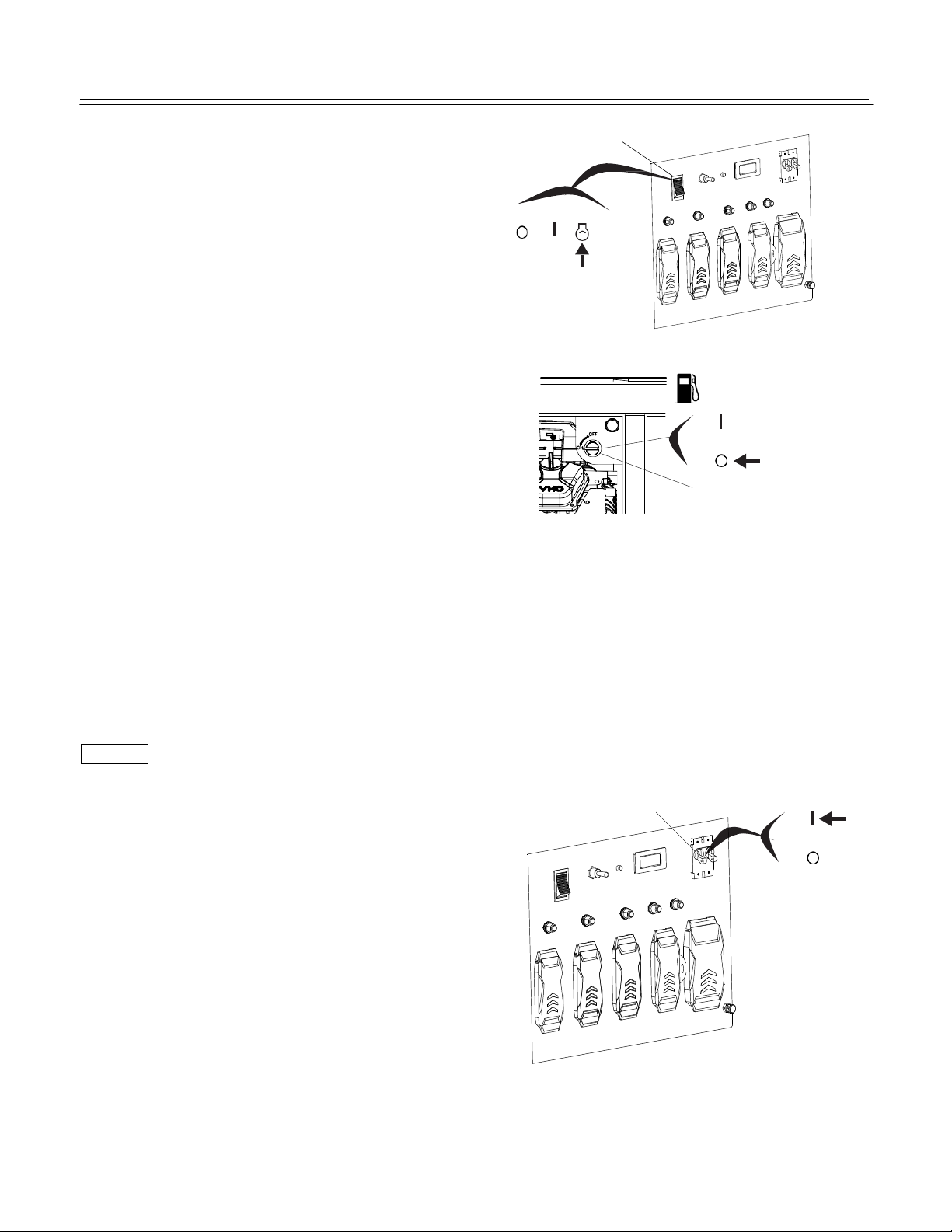
STARTING THE ENGINE
1.
Make sure that the circuit breaker is in the OFF position.
The generator may
2-1.
Turn the fuel valve lever to the ON position
be hard to star
t if a load is connected.
(when using gasoline).
2-2. Connect LPG (when using gasoline)
Connect the LPG connecting pipe to the
LPG port of generator and tighten it;
Connect the LPG connecting pipe to the
LPG tank and tighten it;
Open the fuel valve switch on LPG tank.
2-1. Gasoline
OFF
ON
FUEL VALVE LEVER
OFF
2-2. LPG
CIRCUIT
BREAKER
Page 13

12
CLOSED
CHOKE KNOB
OPEN CHOKE K
OPERATION
NOTICE
3. Pull the choke knob to the CLOSED position to start a cold engine.
Leave the choke knob in the OPEN position to restart a warm engine.
4. Start the engine. Turn the engine switch to the START position, and hold
it there until the engine starts. When the engine starts, release the key,
allowing the switch to return to the RUN position.
If the engine fails to start within 5 seconds, release the key, and wait at
least 10 seconds before operating the starter again.
Using the elec
5.
If the choke knob was pulled to the CLOSED position to start the engine,
tric starter f
or more than 5 seconds at a time will Overheat the starter motor and can damage it.
gradually move it to the OPEN position as the engine warms up.
6.
Generator needs to operate for 3-5 minutes without load, then
it can out put power.
STOP
RUN
STAR
ENGINE SWITCH
NOB
STOPPING THE ENGINE
To stop the engine in an emergency, simply turn the engine switch to the OFF position. Under normal conditions, use
the following procedure.
1.
Move the circuit breaker to the OFF position.
CIRCUIT
BREAKER
ON
OFF
Page 14
13
OPERATION
NOTICE
2. Turn the engine switch to the OFF position (when using gasoline)
3-1. Turn off the fuel valve on LPG tank (when using LPG).
STOP
3-2.
Turn the fuel valve lever to the OFF position(when using
gasoline).
RUN
ENGINE SWICH
STAR
ON
OFF
FUEL VALVE LEVER
.
AC OPERATION
If an appliance beings to operate abnormally, becomes sluggish or stops suddenly, turn it off immediately. Disconnect the
appliance, and determine whether the problem is in the appliance or the rated load capacity of the generator has been
exceeded.
Substantial over loading may damage the generator.Marginal over loading may shorten the service life of the generator.
AC Receptacle
1.
Start the engine (see page 11).
2.
Switch ON the circuit breaker.
3.
Plug in the appliance.
CIRCUIT
BREAKER
ON
OFF
Most motorized appliances require more
than their rated wattage for startup.
Page 15

14
AC Applications
NOTICE
OPERATION
Before connecting an appliance or power c
Make sure that it is in good working order. Faulty appliances or Power cords can create a potential for electrical
shock.
If an appliance begins to operate abnormally, becomes sluggish, or stops suddenly, turn it
off immediately. Disconnect the appliance, and determine whether the problem is the appliance or the rated
load capacity of the generator has been exceeded.
Make sure that the electrical rating of the tool or appliance does not exceed that of the generator. Never exceed
the maximum power rating of the generator. Power levels between rated and maximum may be used for no more
than 30 minutes.
Substantial overloading will open the circuit breaker. Exceeding the time limit for maximum power operation or slightly
overloading the generator may not switch the circuit breaker OFF, but will shorten the service life of the generator.
Limit operation requiring maximum power to 30 minutes.
Maximum power is:
60Hz 15 kVA (GAS);
1 3.5 kVA (LPG);
For continuous operation (longer than 30 minutes), do not exceed the rated power.
Rated power is:
60Hz 12 kVA(GAS);
1 1 kVA (LPG);
ord to the generator:
High Altitude Operation
At high altitude, the standard carburetor air/fuel mixture will be too rich. Performance will decrease, and fuel
consumption will increase. A very rich mixture will also foul the spark plug and cause hard starting. Operation at an
altitude that differs from that at which this engine was certified, for extended periods of time, may increase emissions.
High altitude performance can be improved by specific
modifications to the carburetor. If you always operate your generator at altitudes above 5,000 feet
(1,500 meters), have your dealer perform this carburetor modification. This engine, when operated at high altitude with
the carburetor modifications for high altitude use, will meet each emission standard throughout its useful life. Even with
carburetor modification, engine horsepower will decrease about 3.5% for each 1,000-foot (300-meter) increase in
altitude. The effect of altitude on horsepower will be greater than this if no carburetor modification is made.
Page 16

OPERATION
The total power requirements (VA) of all appliances connected must be considered. Appliance and power tool
manufacturers usually list rating information near the model number or serial number.
STANDBY POWER
Connections to a Building’s Electrical System
Your generator can supply power to a building’s electrical system. If the generator will be used as an alternative to
utility company power, an isolation switch must be installed to disconnect the utility lines from the building when the
generator is connected. Installation must be performed by a qualified electrician and must comply with all applicable laws
and electrical codes.
e areas, generators are required by law to be registered with local utility companies. Check local regulations for
In som
prop
er registration and use procedures.
System Ground
THIS ge
AC output receptacles. The system ground is not connected to the AC neutral wire. If the generator is
teste
nerators have a system ground that connects the generator frame components to the ground terminals in the
d with a receptacle tester, it will not show the same ground circuit condition as for a home receptacle.
Special Requirements
In some areas, gen
If the generator is use
erators are required to be registered with local utility companies.
d at a construction site, there may be additional regulations that must be observed.
15
Page 17

16
SERVICING YOUR GENERATOR
THE IMPORTANCE OF MAINTENANCE
Good maintenance is e
To help you properly care for your generator, the following pages include a maintenance schedule, routine inspection
rocedures, and simple maintenance procedures using basic hand tools. Other service tasks that are more difficult or
p
require
technician or other qualified mechanic.
The maintenance s
unusual conditions,
conditions,
Remember that your servicing dealer knows your generator best and is fully equipped to maintain and repair it.
special tools are best handled
consult your servicing dealer for recommendations applicable to your individual needs and use.
ssential for safe, economical, and trouble free operation. It will also help reduce air pollution.
chedule applies to normal
such
as sustained
by professionals
operating
high
conditions. If you operate your generator
load or high temperature operation, or
and are normally performed by a
use it in dusty
THIS
under
MAINTENANCE SAF
Some of the most important safety precautions follow. However, we cannot warn you of every conceivable hazard that
arise in performing maintenance. Only you can decide whether or not you should perform a given task.
can
Safety Precautions
Make sure t
he engine is off before you begin any maintenance or repairs. This will eliminate several potential hazards:
Carbon monoxide poisoning from engine exhaust.
Be sure there is adequate ventilation whenever you operate the engine.
Burns from hot parts.
Let the engine and exhaust system cool before touching.
Injury from moving parts.
Do not run the engine unless instructed to do so.
ETY
Page 18

SERVICING YOUR GENERATOR
*
Read the instructions before you begin, and make sure you have the tools and skills required.
To reduce the possibility of fire or explosion, be careful when working around gasoline. Use only a nonflammable
solvent, not gasoline, to clean parts. Keep cigarettes, sparks, and flames away from all fuel related parts.
MAINTENANCE SCHEDULE
NOTE:
REFUELING
Wi
(*) Replace the paper element only.
(1)
Service more frequently when used industry areas.
(2)
These items should be serviced by your servicing dealer, unless you have the proper tools and are
mechanically proficient. Refer to our shop manual for service procedures.
(3)
For commercial use, log hours of operation to determine proper maintenance intervals.
Failure to follow this maintenance schedule could result in nonwarrantable failures.
th the engine stopped, check the fuel gauge. Refill the fuel tank if the fuel level is low.
17
Page 19

18
SERVICING YOUR GENERATOR
NOTICE
OIL GAUGE
EMPTY FULL
OIL TA
NK CAP
Refuel in a well ventilated area before starting the engine. If the engine has been running, allow it to cool. Refuel
carefully to avoid spilling fuel. Do not fill the fuel tank above the upper limit mark (red) on the fuel strainer.
Never refuel the engine inside a building where gasoline fumes may reach flames or sparks. Keep gasoline away from
appliance pilot lights, barbecues, electric appliances, power tools, etc.
Spilled fuel is not only a fire hazard, it causes environmental damage. Wipe up spills immediately.
Fuel can damage paint and plast
ic. Be careful not to spill fuel when filling your fuel tank. Damage caused by spilled fuel
is not covered under warranty.
NOTE: Gasoline spo
ils very quickly depending on factors such as light, exposure, temperature and time.
In worst cases, gasoline can be contaminated within 30days.
Using contaminated gasoline can seriously damage the engine (carburetor clogged, valve stuck).
Such damage due to spoiled fuel is disallowed from coverage by the warranty.
To avoid this please st
Only use specified gasoline .
Use fresh and clean gasoline.
To slow deterioration, keep gasoline in a certified fuel container.
If long storage (more than 30 days) is foreseen, drain fuel tank and carburetor (see page 27 ).
FUEL RECOMMENDATIONS
rictly follow these recommendations:
Use automotive unleaded gasoline with a Research Octane Number of 91 or higher (a Pump Octane Number of 86 or
highe
r).
Never use stale or contaminated gasoline or an oil/gasoline mixture.
Avoid getting dirt or water in the fuel tank.
Page 20

SERVICING YOUR GENERATOR
Gasolines Containing Alcohol
If you decide to use a gasoline containing alcohol (gasohol), be sure it’s octane rating is at least as high as that
recommended by this. There are two types of ‘‘gasohol’’: one containing ethanol, and the other containing methanol. D
not use gasohol that contains more than 10% ethanol. Do not use gasoline containing methanol (methyl or wood
alcohol) that does not also contain cosolvents and corrosion inhibitors for methanol. Never use gasoline containing more
than 5% methanol, even if it has cosolvents and corrosion inhibitors.
NOTE:
Fuel system damage or engine performance problems resulting from the use of fuels that contain alcohol is not
covered under the warranty.
THIS cannot endorse the use of fuels containing methanol since evidence of their suitability is as yet incomplete.
Before buying fuel from an unfamiliar station, try to find out If the fuel contains alcohol, if it does, confirm the type
and percentage of alcohol used.
If you notice any undesirable operating symptoms while using a gasoline that contains alcohol, or one that you think
contains alcohol, switch to a gasoline that you know does not contain alcohol.
o
ENGINE OIL LEVEL CHE
Check the engine o
1.
Remove the oil level dipstick and wipe it clean.
2.
Fully insert the dipstick, then remove it to check the oil level.
3.
If the level is near or below the lower limit mark on the dipstick, open the
CK
il level with the generator on a level surface and the engine stopped.
maintenance cover to access the oil filler cap. Remove the oil filler cap, and
fill with the recommended oil to the upper limit mark.
4.
Reinstall the oil level dipstick and filler cap.
OIL LEVEL
DIPSTICK
OIL FILLER CAP
The Oil Alert system will automatically stop the engine before the oil level falls below safe limits. However, to avoid the
inconvenience of an unexpected shutdown, check the oil level regularly.
19
Page 21

SERVICING YOUR GENERATOR
ENGINE OIL CHANGE
Drain the oil while the engine is warm to assure rapid and complete draining.
1.
Place the generator on wooden blocks to make space for placing a suitable container.
2.
Open the maintenance over to access the oil filler cap.
3.
Remove the oil filler cap, oil drain bolt and sealing washer, and drain the oil in to the container.
4.
Install a new sealing washer and the oil drain bolt, and tighten the bolt securely.
5.
Refill to the upper limit mark on the dipstick with the recommended oil. Tighten the oil filler cap securely .
OIL FILLER CAP
Engine oil capacity:
With oil filter replacement:
Approximately 1.6L
Wash your hands with soap and water after handling used oil.
OIL DRAIN BOLT
Please dispose of used motor oil in a manner that is compatible with the environment. We suggest
u take it in a sealed container to your local service station or recycling center for reclamation. Do not throw it in the
yo
trash, pour it on
the ground, or pour it down a drain.
OIL FILTER CHANGE
1.
Drain the engine oil, and tighten the drain bolt securely.
2.
Remove the oil filter, and drain the oil in to a suitable container.Discard the used oil filter.
3.
Clean the filter mounting base, and coat the O-ring of the new oil filter with clean engine oil.
4.
Screw on the new oil filter by hand, until the O-ring contacts the filter mounting base, and then use an
oil filter socket tool to tighten the filter an additional 7/8 turn.
TORQUE: 12N·m (1.2kgf·m)
5.
Refill the crankcase with the specified amount of the recommended Oil . Reinstall the oil filler cap.
6.
Start the engine and check for oil filter leaks.
7.
Stop the engine, and check the oil level as described on
page 21. If necessary, add oil to the upper limit mark on
the dipstick.
OIL FILLER
O-RING
20
Page 22

SERVICING YOUR GENERATOR
PAPER AIR FILTER
ENGINE OIL RECOMMENDATIONS
Oil is a major factor affecting engine performance and service life.
Use 4-stroke automotive detergent oil that meets or exceeds the requirements for API service category SE or later (or
e
quivalent).
SAE 10W-30 is recommended for general use. Other viscosities shown in the chart
m
ay be used when the average temperature in your area is within the recommended
range.
The SAE o
AIR CLEANER SE
1.
2.
il viscosity and service category are on the API label on the oil container.
RVICE
Release four latch tabs from the air cleaner cover, and remove the cover.
Foam air filter:
a.
Remove the foam air filter from the air cleaner housing.
b.
Check the foam air filter to be sure it is clean and in good condition.
Replace the foam air filter if it is damaged.
c.
Reinstall the foam air filter in the air cleaner housing.
3.
Paper air filter:
If the paper air filter is dirty, replace it with a new one. Do not clean the paper air filter.
4.
Reinstall the air cleaner cover.
5.
Close the maintenance cover.
F OAM AIR FILTER
AIR CLEANER COVER
AIR CLEANER COVER
21
Page 23

SERVICING YOUR GENERATOR
NOTICE
Operating the engine without an air filter, or with a damaged air filter, will allow dirt to enter the engine, causing rapid
engine wear.
FOAM AIR F
A dirty foam air filter will restrict air flow to the ca
in very dusty areas, clean the foam air filter more frequently than specified in the Maintenance Schedule.
1.
Clean the foam air filter in warm soapy water, rinse, and allow to dry thoroughly, or clean in non-flammable solvent
and allow to dry.
2.
Dip the foam air filter in clean engine oil, then squeeze out all excess oil. The engine will smoke when started if too
much oil is left in the foam air filter.
SEDIMENT CUP CLEANING
1.
Turn the fuel valve lever to the OFF position, then remove the Sediment cup and the O-ring. Discard the O-ring.
2.
Wipe dirt from the air cleaner housing and cover using a moist rag. Be careful to prevent dirt from entering the air
duct that leads to the carburetor.
ILTER CLEANING
rburetor, reducing engine performance. If you operate the generator
22
Page 24

23
SERVICING YOUR GENERATOR
NOTICE
0.7 - 0.8mm
2.
Clean the sediment cup in nonflammable solvent, and dry them thoroughly.
3.
Install the new O-ring and sediment cup, and tighten the sediment cup securely.
4.
Make sure there is no fuel leakage.
ARK PLUG SERVICE
SP
Recommended spark plugs: F7T
An incorrect spar
If the engine is hot, allow it to cool before servicing the spark plug.
1.
Disconnect the spark plug caps, and remove any dirt from around the spark plug area.
2.
move the spark plugs with a 180mm spark plug wrench
Re
(commercially available).
3.
Inspect the spark plugs. Replace them if the electrodes are worn or if the insulator
is cracked, chipped, or fouled.
k plug can cause engine damage.
C
4.
Measure the spark plug electrode gap with a wire type feeler gauge. Correct the gap, if necessary, by carefully
bending the side electrode.
The gap should be: 0.7 -- 0.8mm
5.
Make sure that the spark plug sealing washers are in good condition, and thread the spark plug in by hand tprevent
cross threading.
6.
After the spark plugs seat, tighten with a 21mm spark plug wrench to compress the washer.
If reinstalling a used spark plug, tighten 1/81/4 turn after the spark plug seats.
If installing
a new spark plug, tighten 1/2 turn after the spark plug seats.
Page 25

SERVICING YOUR GENERATOR
NOTICE
+
_
A loose spark plug can overheat and damage the engine. Over tightening the spark plug can damage the threads in the
cylinder head.
7.
Attach the spark plug caps.
BATTERY SERVICE
Your generator’s engine charging system charges the battery while the engine is running. However, if the generator is
nly used periodically, the battery must be charged monthly to maintain the battery service life.
o
Emergency Procedures
Eyes -- Flush with water from a cup or other container for at least fifteen minutes. (Water under pressure can damage
the eye.)
Immediately call a physician.
Skin -- Remove contaminated clothing. Flush the skin with large quantities of water. Call a physician immediately.
Swallowing -- Drink water or milk. Call a physician immediately.
Battery Removal
WARNING: Ba
lead and lead compounds. Wash hands after handling.
1.
Remove the negative (-) cable from the
battery negative (-) terminal first, and
then remove the positive () cable from
the battery positive (+) terminal.
2.
Remove the flange nuts, and remove the battery set plate.
3.
Remove the battery from the battery tray.
ttery posts, terminals, and related accessories contain
24
Page 26

25
SERVICING YOUR GENERATOR
This symbol on the battery means that this product must not be treated as household waste.
NOTE:
properly disposed of battery can be harmful to the environment
An im
and human health.
Always confirm local regulations for battery disposal.
Battery Charging
The battery is rated at 21.0Ah (ampere hours). Charging current should equal 10% of the battery’s ampere hour rating.
1.
Connect the battery charger following the manufacturer’s instructions.
2.
Charge the battery.
3.
Clean the outside of the battery and the battery compartment with a solution of baking soda and water.
Battery Installation
1.
Install the battery into the generator.
2.
Connect the battery positive (+) cable to the battery positive (+) terminal first, and tighten the bolt securely.
3.
Slide the battery boot over the positive (+) cable and terminal.
4.
Connect the battery negative (-) cable to the battery negative (-) terminal, and tighten the bolt securely.
Page 27

STORAGE
STORAGE PREPARATION
Proper storage preparation is essential for keeping your generator trouble free and looking good. The following steps
will help to keep rust and corrosion from impairing your generator’s function and appearance, and will make the engine
easier to start when you use the generator again.
Cleaning Wipe the generator with a moist cloth. After the generator has dried, touch up any damaged paint, and coat other areas that may rust with a light film of oil.
Fuel
Gasoline will oxidize and deteriorate in storage. Old gasoline will cause hard starting, and it leaves gum deposits that
clog the fuel system. If the gasoline in your generator deteriorates during storage, you may need to have the carburetor
and other fuel system components serviced or replaced.
NOTE:
Gasoline spoils very quickly depending on factors such as light exposure, temperature and time.
In worst cases, gasoline can be contaminated within 30days.
Using contaminated gasoline can seriously damage the engine (carburetor clogged, valve stuck).
Such damage due to spoiled fuel is disallowed from coverage by the warranty.
To avoid this please strictly follow these recommendations:
Only use specified gasoline .
Use fresh and clean gasoline.
To slow deterioration, keep gasoline in a certified fuel container.
If long storage (more than 30days) is foreseen, drain fuel tank and carburetor (see page 27).
You can extend fuel storage life by adding a gasoline stabilizer that is formulated for that purpose, or you can avo
deterioration problems by draining the fuel tank and carburetor.
Adding a Gasoline St
When adding a gasoline stabilizer, fill the fuel tank with fresh gasoline. If only partially filled, air in the tank will promote
fuel deterioration during storage. If you keep a container of gasoline for refueling, be sure that it contains only
fresh gasoline.
1.
Add gasoline stabilizer following the manufacturer’s instructions.
2.
After adding a gasoline stabilizer, run the engine outdoors for 10 minutes to be sure that treated gasoline has replaced
the untreated gasoline in the carburetor.
3.
Stop the engine, and turn the fuel valve lever to the OFF position.
abilizer to Extend Fuel Storage Life
id fuel
26
Page 28

27
STORAGE
STORAGE PROCEDURE
1.
Drain the fuel tank and carburetor.
a.
Unscrew the fuel tank cap, remove the fuel filter, and empty the
fuel tank into an approved gasoline container. We recommend
using a commercially available gasoline hand pump to empty
the tank. Do not use an electric pump. Reinstall the fuel filter
and the fuel tank cap.
b.
Pull out the carburetor drain tube end under the fan cover of the engine, and place it in a suitable container.
c.
Loosen the carburetor drain screw.
d.
Drain the gasoline from the carburetor into the container.
e.
Tighten the carburetor drain screw securely.
2.
Change the engine oil (refer to page 20).
3.
Remove the spark plugs (see page 23).
4.
Pour a table spoon (5-10cc) of clean engine oil into each cylinder.
5.
Turn the engine for a few seconds by turning the engine switch to the START position to distribute the oil in
the cylinders.
6.
Reinstall the spark plugs.
7.
Remove the battery and store it in a cool, dry place. Recharge it once a month.
8.
Cover the generator to keep out dust.
Page 29

STORAGE
STORAGE PRECAUTIONS
If your generator will be stored with gasoline in the fuel tank and carburetor, it is important to reduce the hazard of
gaso
line vapor ignition.
Select a well ventilated storage area away from any appliance that operates with a flame, such as a furnace, water heater, or
clothes dryer. Also avoid any area with a spark producing electric motor, or where power tools are operated.
If possible, av
Unless all fu
leakage.
Place the g
With the engine and exhaust system cool, cover the generator to keep out dust. A hot engine and exhaust system can
ign
ite or melt some materials.
Do not u
corrosion.
oid storage areas with high humidity, because that promotes rust and corrosion.
el has been drained from the fuel tank, leave the fuel valve lever in the OFF position to reduce the possibility of
enerator on a level surface. Tilting can cause fuel or oil leakage.
se sheet plastic as a dust cover. A nonporous cover will trap moisture around the generator, promoting rust and
REMOVAL FROM S
Check your generator as described in the BEFORE OPERATION chapter of this manual.
If the fuel was drained during to rage preparation, fill the tank with fresh gasoline. If you keep a container of gasoline
refueling, be sure that it contains only fresh gasoline. Gasoline oxidizes and deteriorates overtime,
for
causing hard starting.
TORAGE
28
Page 30

29
TRANSPORTING
If the generator has been running, allow the engine to cool for at least 15 minutes before loading the generator on the
transport vehicle. A hot engine and exhaust system can burn you and can ignite some materials.
Keep the generator level when transporting to reduce the possibility of fuel leakage. Move the fuel valve lever to the
OFF po
sition.
When using ropes or tied owns traps to secure the generator for transportation, be sure to only use the frame bars as
a
ttachment points. Do not fasten ropes or straps to any portions of the generator body.
Page 31

TAKING CARE OF UNEXPECTED PROBLEMS
Engine Will Not Start Possible Cause Correction
1.
Check control positions
2.
Check fuel
3.
Check engine oil level.
4.
Remove and inspect spark
plug.
5.
Take generator to an
authorized THIS
vicing dealer, or refer
ser
to shop manual.
Fuel valve lever OFF. Tur
Choke OPEN. Move to CLOSED
Engine switch OFF. Turn engine switch to ON.
Out of fuel. Refuel (p
Bad fuel; generator stored without
treating or draining gasoline, or refueled
with bad gasoline.
Low oil level c
engine.
k plug faulty, fouled, or improperly
Spar
gapped.
Spark plug wet with fuel (flooded engine). Dry and reinstall spark plug.
Fuel filter restricted, carburetor
malfunc
stuck etc.
aused Oil Alert to stop
tion, ignition malfunction, valves
n lever ON.
.18).
Drain fuel tank and carburetor
(p.27).Refuel with fresh
gasoline(p.18).
Add oil (p.20). Turn engine switch to
OFF and restart the engine.
Gap, or replace spark plug (p.23
Replace or repair f
as necessary.
aulty components
).
Engine Lacks Power Possible cause Correction
1.
Check air filter. Air filter restricted.
Bad fuel; generator stored without
2.
Check fuel.
3.
Take generator to an
authorized THIS
vicing dealer, or refer
ser
to shop manual.
tre
ating or draining gasoline, or refueled
with bad gasoline.
Fuel filter restricted, carburetor
malfunc
stuck etc.
tion, ignition malfunction, valves
Clean or replace air filter (p.22)
Drain fuel tank and carburetor (p.27).
Refuel with fresh gasoline
(p.18)
Replace or repair f
as necessary.
aulty components
30
Page 32

TAKING CARE OF UNEXPECTED PROBLEMS
N
o Power at the AC
Receptacles
1.
Check circuit breaker.
2.
Check the power tool or
appliance at a known
d AC power source.
goo
3.
Take generator to an
authorized THIS
rvicing dealer, or refer
se
to shop manual.
Possible cause Correction
Circuit breaker l
after starting.
Faulty power tool or applianc
Faulty generator.
eft in the OFF position
e.
Switch circuit b
Replace or repair power tool or
appliance
Replace or r
necessary.
reaker ON.
. Stop and restart the engine.
epair faulty components as
31
Page 33

32
TECHNICAL INFORMATION
CARBURETOR MODIFICATION FOR HIGH ALTITUDE OPERATION
At high altitude, he standard carburetor air-fuel mixture will be too rich. Performance will decrease, and fuel consumption
will increase. A very rich mixture will also foul the spark plugs and cause hard starting.
Operation at an altitude that differs from that at which this engine was certified, for extended periods of time, may increase
emissions.
High altitude performance can be improved by specific modifications to the carburetor. If you always operate your
generator at altitudes above 1,500 meters, have your authorized THIS servicing dealer perform this carburetor
modification.
Even with carburetor modification, engine horsepower will decrease about 3.5% for each 300 meter increase in altitude.
NOTICE
When the carburetor has been modified for high altitude operation, the air/fuel mixture will be too lean for low altitude use.
Operation at altitudes below 1,500 meters with a modified carburetor may cause the engine to overheat and result
in serious engine damage. For use at
Low altitudes, have your servicing dealer return the carburetor to original factory specifications.
Page 34

TECHNICAL INFORMATION
SPECIFICATIONS
Dimensions
Model
Length 34.25 Inches
Width
Height
Dry mass(weight)*
PG15KVTWB
23 Inches
28.5 Inches
474 lbs.
*with baery
Engine
Model
DHTLG720E
Engine Type 4-stroke,overheadvalve,2cylinder
Displacement 713cc
Bore & Stroke 80*71mm
Cooling System Forced air
Ignion System Transistorized magneto ignion
Oil Capacity With oil filter replacement approximatly 1.6L
Fuel Tank Capacity 40L
Spark Plug F7TC(NHSPLD)
Baery 12V/21AH
Generator
Model
Single-phase
Rated voltage 120V/240V
60Hz
91.6A/45.8A
AC output
Rated frequency
Rated Ampere
100A/50A
Rated output 12kW(GAS) 11kW(LPG)
Maximum output 15kW(GAS) 13.5kW(LPG)
Power factor 1
Tune up Specificaons
ITEM SPECIFICATION MAINTENANCE
Spark plug gap 0.7-0.8mm Refer to page: 23
Valve clearance(cold)
IN:0.08-0.12mm EX:0.13-0.17mm See your authorized dealer
Other specificaons No other adjustments needed.
Specificaons may vary according to the types, and are subject to change without noce.
33
Page 35

TECHNICAL INFORMATION
WIRING DIAGRAM
34
Page 36

WARRANTY
Pulsar Products Inc. Limited 2 Year Warranty:
From the date of original purchase, Pulsar Products Inc. warrants to the original purchaser that each portable generator
sold, shall be free from defect in material and workmanship for the items and time period set forth below. Pulsar Products
Inc., at its discretion, agrees to repair or replace any defective part that upon examination, inspection, and testing by
a Pulsar Products Inc. authorized service dealer, is found to be defective within the original warranty period. Pulsar
Products Inc. will also decide upon the use of new or rebuilt parts or comparable product. Any part or product that is replaced
will be retained by Pulsar Products Inc.. This warranty period shall not be extended and any repaired product shall be
warranted for the remaining period of the original warranty. The consumer is responsible, and shall prepay all transportation
costs, including returning items to the factory or warehouse. This warranty is non-transferable and proof of purchase must
be presented for requesting warranty service. If a proof-of-purchase receipt is not provided, the product’s shipping date by
the manufacturer will be used to determine the warranty period.
Length of Warranty:
Personal use applications of this portable generator are warranted for two (2) years or 500 hours which ever comes first.
Proof of purchase and of maintenance must be provided.
• Year 1 - Limited coverage on generator engine and alternator components parts and labor.
• Year 2 - Limited coverage on generator engine components, parts only.
“Personal use” means personal residential household use or recreational use by the retail consumer. “Commercial use”
means all other uses including commercial, construction, or other income producing purposes. Once a generator has been
used for commercial purposes, it shall thereafter be considered as a “commercial use” generator for the purposes of this
warranty. Any portable generator used for commercial use, as rental equipment or for the purpose of primary power in place
of utility, will not be covered under this warranty.
Consumer Responsibilities:
• Consumer is responsible for carefully reading and following all instructions in the owner’s manual. Any product that is
damaged due to misuse or abuse will not be covered by this warranty.
• Consumer is responsible for all transportation costs to an authorized Pulsar Products Inc. Service Center. Unless
otherwise requested, ground shipping will be applied for part shipment and customer will pay any additional charges for
expedited shipments.
• Consumer is responsible for labor costs associated with warranted repairs twelve (12) months after the purchase date.
Labor rates will only be based on normal working hours.
Consumer is responsible for maintaining generator as specified in the owner’s manual. Documentation of this
•
maintenance may be required to cover warranty requests.
• Consumer is responsible for presenting any problems with the generator to an authorized Pulsar Products Inc.
Service Center as soon as the problem exists. Warranted repairs will be completed in a reasonable period of time, not
to exceed 30 days.
Page 37

WARRANTY
What this Warranty Does Not Cover:
• Normal wear: This warranty excludes normal wear items such as filters, spark plugs, gaskets, O-rings, adapter cord
sets, wheels, and starting batteries.
• Maintenance: This warranty does not apply to tune-ups or routine maintenance and does not cover any adjustments or
repairs not performed by an authorized repair facility.
• Misuse: This warranty does not apply if your product has failed due to abuse, misuse, neglect, using incorrect fuels or
lubricants, overloading, overspeeding, improper maintenance, improper storage, unapproved modifications, or has been
operated in any way contrary to the instructions found in the products owner’s manual.
• Adverse conditions: This warranty does not apply if your product has failed due to freezing, accident or natural
disasters.
• Product shipment: This warranty does not apply to damage resulting from shipping, handling, or warehousing. Any
damage claims to this product caused by shipment must be filed with freighter.
• Other exclusions: This warranty does not apply if your product has been sold “as is” or where the factory applied serial
number has been removed. Refurbished, used, demonstration or floor models are not covered by this warranty.
Where Warranty is Valid:
For warranty coverage, this product must be purchased from an authorized Pulsar Products Inc. dealer and the warranty
only extends to the original purchaser in the United States, Canada, or Mexico. Refurbished, used, demonstration, or floor
models are not covered by this warranty. Products purchased from on-line auction websites, such as ebay, are not covered
under this warranty. Products used for commercial use are not covered under this warranty.
How to Obtain Warranty Service:
Take the original receipt and product to the place of purchase or mail the original receipt and product to the address found
on the web site if purchased on-line. You can also locate your nearest Pulsar Products Inc. dealer for service or warranty
questions by calling toll free at 1-866-591-8921.Pulsar Products Inc. recommends you retain all of your receipts
covering the purchase and maintenance of your Portable Generator, but will not deny you warranty coverage as long as
proof of purchase or service can be obtained.
Pulsar Products Inc.’s obligation under this warranty is exclusively limited to product repair or replacement and
shall not be liable for any incidental or consequential damages including, but not limited to, the expense of
delivering product to and from a repair center, loss or damage to personal property, loss of revenue, telephone
charges, loss of time, or inconvenience. Some states, provinces or jurisdictions do not allow the exclusion or
limitation of incidental damages, so the above limitation may not apply to you. The warranty gives you specific
legal rights, and you may also have other rights which vary from state to state or province to province.
Image of products may slightly differ due to continued improvement of product.
IM PG15KVTWB
Rev.A 012019
 Loading...