

Page 1
UB20.241
UB
DC-UPS C
G
S
Input
18
Output voltage
in power supply
mode
22.5V, 24V, 25V,
26V (selectable)
in battery mode
Output current
25A continuous
30A for 4s
in power supply
mode
20A continuous
30A for 4s
in battery mode
at 22.5V
Allowed battery
sizes
3.9 – 150Ah
2 batteries in
series, each 12V
Buffer time
6min 45s
at 20A, 7Ah
16min 47s
at 20A, 12Ah
2h 49min
at 20A, 65Ah
6h 20min
at 20A, 140Ah
Temperature range
-40°C to +70°C
operational
Derating
+6
Dimensions
W x H x D
Weight
O
M
IND. CONT. EQ.
-Series
ENERAL DESCRIPTION
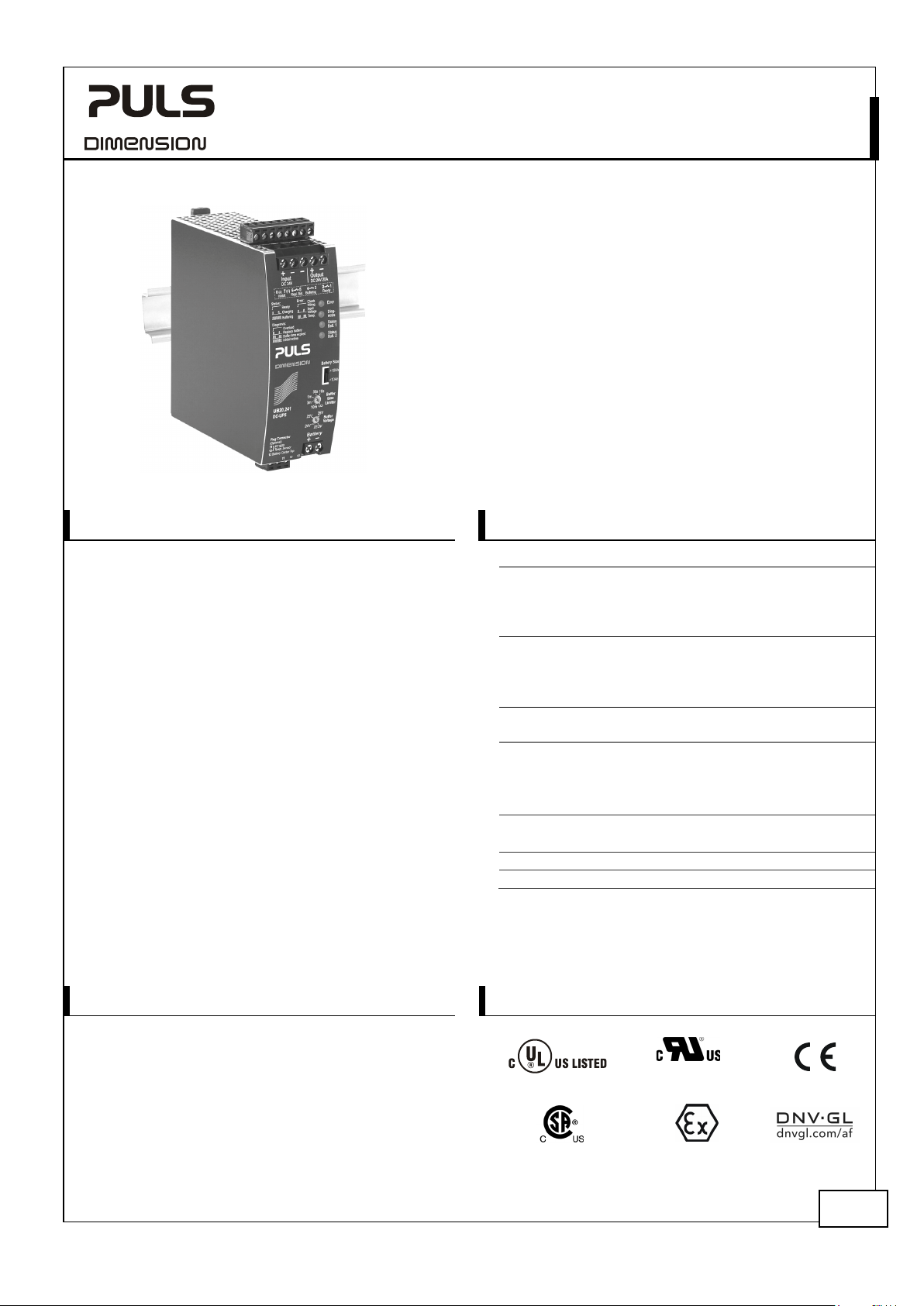
The UB20.241 uninterruptible power supply controller
(DC-UPS) is used in addition with a 24V power supply
and batteries to bridge power failures or voltage
fluctuations. This configuration can prevent expensive
downtimes, long restart cycles and loss of data.
A unique feature of the UB20 series is the constant
voltage in battery mode, which will not change as the
batteries discharge. The buffer voltage in battery mode
can be set to four different output values. Another
feature is the utilization of two independent battery
chargers for the two 12V-batteries in series. This feature
makes matching batteries unnecessary and allows for
precise battery charging, testing and optimized usage
of the battery capacity to achieve the longest battery
service life.
The UB20.241 includes many battery diagnostic
functions that ensure a reliable operation of the entire
system. Furthermore, a temperature controlled charging
extends the life of the batteries. It also includes a
selectable buffer time limiter as well as ready, buffering
and replace battery contacts. For safety and
maintenance, an inhibit input signal is included which
prevents a battery backup.
24V, 20A, DC-UPS
ONTROL UNIT
No Change in Output Voltage in Battery Mode
Selectable Output Voltages in Battery Mode
1-Battery-Concept
Each 12V Battery is Charged and Monitored Separately
for Longest Battery Life
Precise Battery Charging by Using a Temperature Sensor
Battery Size Selector for Small or Large Batteries
50% BonusPower
High Breaking Capacity for Branch Protectors
Smart Battery Diagnostics and Monitoring Functions
3 Year Warranty
®
, 30A for up to 4s
HORT-FORM DATA
voltage DC 24V
same as input
voltage
0.5A/°C
46x 124x 127mm
700g / 1.54lb
-±25%
-30Vdc
0°C to +70°C
RDER NUMBERS
DC-UPS UB20.241 Standard DC-UPS unit
Accessory UZK24.071 Battery module 24V, 7Ah
Aug. 2019 / Rev. 2.2 DS-UB20.241-EN
All parameters are specified at 24V, 20A output current, 25°C ambient and after a 5 minutes run-in time unless otherwise noted.
ARKINGS
UZO24.071 UZK24.071 without batteries
UZK24.121 Battery module 24V, 12Ah
UZO24.121 UZK24.121 without batteries
UZS24.100 Sensor & center tap board
ZM2.WALL Panel/ wall-mount bracket
ZM12.SIDE Side-mount bracket
Class I Div 2
IECEx ATEX
I.T.E.
II 3G Ex nA nC II T4 Gc
Marine
1/31
Page 2

UB20.241
UB
I
-Series
NDEX
Page Page
1. Terminology and Abbreviations .........................3
2. Intended Use .......................................................4
3. Installation Notes ................................................4
4. Input / Output .....................................................6
5. Batteries and Battery Charging ........................ 10
6. Buffer Time ........................................................ 12
7. Ready and Buffering Relay Contact ................. 14
8. Replace Battery Relay Contact .......................... 14
9. Inhibit Input....................................................... 14
10. Efficiency and Power Losses.............................. 15
11. Lifetime Expectancy and MTBF ......................... 15
12. Functional Diagram ........................................... 16
13. Terminals and Wiring ........................................ 16
14. Front Side and User Elements ........................... 17
15. EMC .................................................................... 19
16. Environment ...................................................... 20
17. Protection Features ........................................... 21
18. Safety Features .................................................. 21
19. Dielectric Strength ............................................ 22
24V, 20A, DC-UPS
20. Approvals .......................................................... 22
21. Physical Dimensions and Weight ..................... 23
22. Accessories ........................................................ 24
22.1. ZM2.WALL – Wall-Mounting Bracket ...... 24
22.2. ZM12.SIDE – Wall-Mounting Bracket ...... 24
22.3. UZS24.100 – Sensor Board for DC-UPS ..... 24
22.4. UZK24.071 – 24V, 7AH Battery Module ... 25
22.5. UZK24.121 – 24V, 12AH Battery Module . 25
23. Application Notes ............................................. 26
23.1. Battery Replacement Intervals ................. 26
23.2. External Input Protection ......................... 28
23.3. Output Circuit Breakers ............................ 28
23.4. Back-feeding Loads .................................. 28
23.5. Parallel Use to Increase Output Current .. 29
23.6. Parallel Use for Redundancy .................... 29
23.7. Series Use for 48V Applications ............... 30
23.8. Using the Inhibit-Input ............................. 30
23.9. Troubleshooting ....................................... 31
The information presented in this document is believed to be accurate and reliable and may change without notice.
No part of this document may be reproduced or utilized in any form without permission in writing from the publisher.
Aug. 2019 / Rev. 2.2 DS-UB20.241-EN
All parameters are specified at 24V, 20A output current, 25°C ambient and after a 5 minutes run-in time unless otherwise noted.
2/31
Page 3

UB20.241
UB
1. T
-Series
24V, 20A, DC-UPS
ERMINOLOGY AND ABBREVIATIONS
DC-UPS Abbreviation for Uninterruptible Power Supply system with a DC input and a DC output.
A DC-UPS utilizes batteries as back-up energy source.
Power supply mode Describes a condition where the input voltage is in the rated input voltage range and the
supplying power supply can deliver a sufficient amount of current for the DC-UPS and the
load. Additionally it is assumed that the output is loaded within the allowed limits and the
battery is charged, if necessary.
The mode can also be called “Normal mode”.
Battery mode Describes a condition where the input voltage is below the transfer threshold level, the unit
is running on batteries (buffering) and the output is loaded within the allowed limits.
The mode can also be called “Buffer mode”.
Normal mode see “Power supply mode”
Buffer mode see “Battery mode”
Inhibit mode Describes a condition where buffering is disabled on purpose (e.g. for service actions).
T.b.d. To be defined, value or description will follow later.
DC 24V A figure displayed with the AC or DC before the value represents a nominal voltage with
standard tolerances included.
E.g.: DC 12V describes a 12V battery disregarding whether it is full (13.7V) or flat (10V).
24Vdc A figure with the unit (Vdc) at the end is a momentary figure without any additional
tolerances included.
may A key word indicating flexibility of choice with no implied preference.
shall A key word indicating a mandatory requirement.
should A key word indicating flexibility of choice with a strongly preferred implementation.
Aug. 2019 / Rev. 2.2 DS-UB20.241-EN
All parameters are specified at 24V, 20A output current, 25°C ambient and after a 5 minutes run-in time unless otherwise noted.
3/31
Page 4

UB20.241
UB
2. I
3. I
-Series
24V, 20A, DC-UPS
NTENDED USE
This device is designed for installation in an enclosure. Use an appropriate enclosure which protects against
mechanical, electrical and fire hazards.
This device is intended for professional use in areas such as in industrial control, office, communication, and
instrumentation equipment.
Do not use this device in equipment or systems where malfunction may cause severe personal injury or threaten
human life.
NSTALLATION NOTES
This device may only be installed and put into operation by qualified personnel.
The input must be powered from a SELV or PELV power source.
Use DIN-rails according to EN 60715 with a height of 7.5 or 15mm.
Mounting orientation must be output and input terminals on top.
Do not obstruct air flow as the unit is convection cooled. Ventilation grid must be kept free of any obstructions.
Use an appropriately sized 24V power supply, which can deliver the additional required internal current consumption
(including the charging current) specified as input current in the table of chapter 4.
Install the batteries outside the cabinet or in a place, where the batteries will not be heated by adjacent equipment
and ensure sufficient ventilation for the batteries as required in the EN 50272-2 standard.
2
Use wires not smaller than 4mm
batteries and the DC-UPS. Longer or thinner wires can change performance of the DC-UPS system.
®
Use a 35A fuse (ATOF
The battery fuse protects the wires between the battery and the DC-UPS and shall be located close to the battery. If
PULS battery modules are used, this fuse is already included.
Use a 4A fuse (ATOF
point of the two 12V batteries and the “Center TAP” connection point of the DC-UPS. An equivalent protection is
included on the PULS battery modules or the PULS UZS24 sensor board. Please note: The center tap connection is not
mandatory but enables an individual charging and monitoring of the two batteries.
Optionally, a PT1000 temperature sensor can be connected to terminals point 11 and 12 to measure the battery
temperature. This adjusts the charging voltage according to the battery temperature which extends the battery life.
This sensor is already installed in the PULS battery modules (UZK24) and the PULS UZS24.100 sensor board.
The following installation clearances must be maintained when the device is loaded permanently with more than 50%
of the rated power:
- Left / right: 5mm (15mm in case the adjacent device is a heat source)
- On top of the unit: 40mm
- On bottom of the unit: 20mm
Agency approvals apply only for altitudes up to 2000m.
Maximum surrounding air temperature: 70°C / 158°F.
A disconnecting means shall be provided for the output and battery input when used in applications according to CSA
C22.2 No 107.1-01.
287 035 from Littelfuse or an UL listed fuse with the same characteristics) in the battery path.
®
287 004 from Littelfuse or an UL listed fuse with same characteristics) between the connection
(or AWG 12) and not longer than 2x1.5m (equal 1.5m cord length) between the
Aug. 2019 / Rev. 2.2 DS-UB20.241-EN
All parameters are specified at 24V, 20A output current, 25°C ambient and after a 5 minutes run-in time unless otherwise noted.
4/31
Page 5

UB20.241
UB
WARNI NG
24V Power
Supply
+
-
UB20.241
Input
+-+
-
24V Battery
Module
+
Buffered
Load
+
-
Non-
buffered
Load
+
-
24V
buffered
branches
24V
Non-bufferd
branches
Temp.
Sensor
Output
Battery
-
Bat1
12V
Bat2
12V
Center Tap
Temp. Sensor
DC-UPS
AC
DC
Output
Input
N L PE
+
+
optional
UZK24
-Series
24V, 20A, DC-UPS
Risk of electrical shock, fire, personal injury or death.
- Turn power off and disconnect the battery fuse before working on the device. Protect against inadvertent re-
powering.
- Make sure that the wiring is correct by following all local and national codes.
- Do not modify or repair the unit.
- Do not open the unit as dangerous voltages may be present inside.
- Use caution to prevent any foreign objects from entering the housing.
- Do not use in wet locations or in areas where moisture or condensation can be expected.
- Do not touch during power-on, and immediately after power-off. Hot surfaces may cause burns.
- Always dispose the batteries through a recycling organization. Batteries must be completely discharged before
recycling.
Fig. 3-1 Typical wiring diagram
Aug. 2019 / Rev. 2.2 DS-UB20.241-EN
All parameters are specified at 24V, 20A output current, 25°C ambient and after a 5 minutes run-in time unless otherwise noted.
5/31
Page 6
UB20.241
UB
4. I
Battery
Mode
Output
Voltage
Input
Voltage
t
t
Transfer Threshold
Power
Supply
Mode
Power
Supply
Mode
Temporarily
allowed No Charging,
no Buf
fering
D: 26V
C: 25V
B: 24V
A: 22.5V
27V
26V
25V
23.5
V
30V30V30V30V
30V
18V
35V
Buffer Voltage Settings
Four Ranges:
26V25V24V22.5V
Normal
Operating
Voltage
(4 Ranges)
Buffer
Voltage
Rated Input Voltage Range
Battery Mode
0V
DCBA
Range A
Range B
Range C
Range D
-Series
24V, 20A, DC-UPS
NPUT / OUTPUT
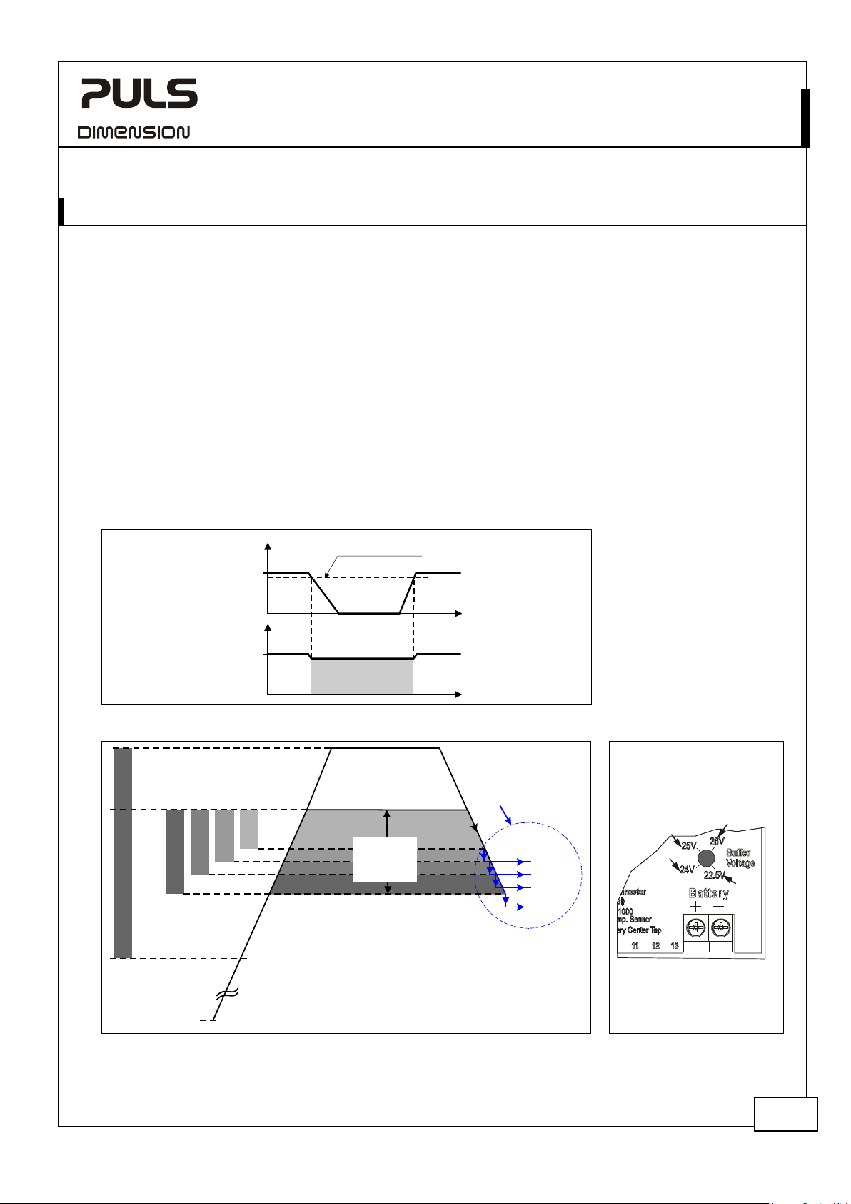
The output is connected to the input through a back-fed protection (MOSFET). In power supply mode, the output
voltage follows the input voltage decreased by a small voltage loss. In battery mode, the output voltage is a constant
voltage, which can be preselected in one of four voltages.
Input Voltage Range:
At voltages within the input voltage range, control functions such as LEDs, monitoring features, relay contacts, etc. are
functioning normally. Within the input voltage range the unit can either be in power supply mode or in battery mode.
Normal Operating Voltage Ranges (four ranges):
The normal operating voltage range describes the input voltage, which supports the full functionality of the DC-UPS
(including charging) but without entering the battery mode. It requires a minimum of 1V higher than the buffer
voltage settings and a maximum voltage of not more than 30Vdc.
Buffering and Buffer Voltage:
Buffering will start immediately without interruption after the input voltage falls below the lower end of the normal
operating voltage range. Buffering is possible even if the batteries are not fully charged.
Buffering can not be started without having previously entered the normal operating voltage range.
The buffer voltage is the output voltage determined by “the buffer voltage setting” and will not change as the
batteries discharge. The buffer voltage is pre-selectable in one of four voltages.
Fig. 4-1 Definition of “power supply mode” and “battery mode”
ig. 4-3 Buffer voltage
Fig. 4-2 Input Voltag e Ranges
Aug. 2019 / Rev. 2.2 DS-UB20.241-EN
All parameters are specified at 24V, 20A output current, 25°C ambient and after a 5 minutes run-in time unless otherwise noted.
F
Settings on the front
6/31
Page 7
UB20.241
UB
Input voltage
Input voltage
Normal operating
ranges
Transfer voltage for switching
into battery mode
Output voltage
Ripple and
Requirements for
supply on the input
Input current
-Series
nom. DC 24V
range nom. 18-30Vdc Control functions such as LEDs, monitoring features,
input voltage
in power supply mode typ.
in battery mode nom.
noise voltage
in power supply mode
in battery mode max.
the power
internal consumption
total input current max. Sum of the output (load) current and the internal current consumption
Footnotes can be found on the next page.
24V, 20A, DC-UPS
-±25%
relay contacts, etc. are working. The unit can either be
in power supply mode or in battery mode. See Fig. 4-2.
max. 30-35Vdc Temporarily allowed, no damage to the DC-UPS.
The red error LED will report “Input Voltage”, charging
and buffering are not possible. See Fig. 4-2.
max. 35Vdc Absolute max. voltage with no damage to the unit.
Ranges, where the unit does not switch to battery
mode. See Fig. 4-2.
typ.
typ.
typ.
typ.
typ.
typ.
typ.
typ.
nom.
nom.
nom.
typ. 80mA When batteries are fully charged
max.
max.
23.5 – 30Vdc
25 – 30Vdc
26 – 30Vdc
27 – 30Vdc
Range A for a 22.5V buffer voltage setting
Range B for a 24V buffer voltage setting
Range C for a 25V buffer voltage setting
Range D for a 26V buffer voltage setting
Please note: The lower end must be at least 1V higher
than buffer voltages settings.
23.5Vdc
25Vdc
26Vdc
27Vdc
0.12V less than
input voltage
at 20A
22.5Vdc
24.0Vdc
25.0Vdc
26.0Vdc
±3%
±3%
±3%
±3%
not applicable
120mVpp
Range A, 22.5V buffer voltage
Range B, 24V buffer voltage
Range C, 25V buffer voltage
Range D, 26V buffer voltage
The output voltage is always slightly lower than the
input voltage, independent of the value of the input
voltage. See Fig. 4-4 and Fig. 4-5.
The buffer voltage is the output voltage in battery
mode, selectable in four steps via rotary switch on the
front of the unit and will not change as the batteries
discharge. See Fig. 4-2.
better as the supplying power supply (filter included)
20Hz to 20MHz, 50Ohm
- Use an appropriately sized 24V power supply, which can deliver the
additional required internal current consumption of the DC-UPS and the
required current for charging the batteries. See also Fig. 4-6.
- Use power supplies that do not deliver more than 28A continuous
output current
2.1A / 4.0A
1)
.
For <10Ah / >10Ah settings; during battery charging,
no temperature sensor installed
2.3A / 4.3A
For <10Ah / >10Ah settings; during battery charging,
temperature sensor is installed
Aug. 2019 / Rev. 2.2 DS-UB20.241-EN
All parameters are specified at 24V, 20A output current, 25°C ambient and after a 5 minutes run-in time unless otherwise noted.
7/31
Page 8

UB20.241
UB
Output current
(dynamic peak current), see Fig. 4-9.
Overload behavior
Output short circuit current
Return current
Allowed voltage between input
and earth (chassis)
Capacitive and inductive lo
Input to Output Voltage Loss, typ.
0mV
10A
30mV
60mV
90mV
120mV
25A
20A
Output Current
0
150mV
AB
A... 25°C
B... 60°C
5A 15A
180mV
V
Power
Supply
+
-
U
IN
Voltage Loss UIN= U
OUT
-
A
V
I
OUT
U
OUT
Variable
Load,
0-25A
UB20.241
Input Output
-Series
24V, 20A, DC-UPS
in power supply mode
in battery mode
in power supply mode
in battery mode
in power supply mode
in battery mode typ.
nom.
nom.
nom.
nom.
typ.
25A
30A
20A at 22.5V,
18A at 26V
30A at 22.5V,
26A at 26V
80A
not limited
PLUS
Hiccup
Mode
not limited
31A for 2 sec
Continuously allowed
For max. 5s
Continuously allowed see Fig. 4-7
(interpolate linearly between 22.5V and 26V)
For typ. 4s (BonusPower
® 4)
) see Fig. 4-7
(interpolate linearly between 22.5V and 26V)
For typ. 25ms, output voltage stays above 20V,
1)
Description see footnotes
and
2)
Description see footnote 3)
1)
2)
Description see footnotes
and
50mOhm impedance, repetitive pulses, see Fig. 4-8.
typ. -200µA Leakage current to the input of the DC-UPS in battery
mode
max. 60Vdc or
42.4Vac
continuous, IEC 62103
ads No limitation
1) Use a 25A melting fuse with a melting I2t of 400A2s – 1500A2s or a 25A circuit breaker with tripping characteristic B, C, D or K on the input
of the DC-UPS if the current of the power supply is higher than 28A.
2) The DC-UPS has no current limiting feature included in power supply mode. The current is limited by the supplying power supply or the
fuse/ circuit breaker, which must be installed when the power supply has a continuous output current capability of more than 28A.
3) Hiccup
4) BonusPower
PLUS
Mode:
In battery mode, the DC-UPS can deliver 50% more output current for a period of up to 4s before it reduces the output current
automatically to the nominal output current. If the current requirement is continuously higher than the nominal current, the current
regulation of the DC-UPS reduces the output voltage. As soon as the output voltage falls below 18V, the output switches off and makes a
restart attempt every 17s. This cycle is repeated as long as the overload exists.
®
:
The DC-UPS is designed to support loads with a higher short-term power requirement without damage or shutdown. In battery mode,
the short-term duration is hardware controlled by an output power manager. At 150% output current, it is typically 4s and longer for
lower currents. Once the BonusPower® time is exceeded, the maximum output current is automatically reduced to the nominal output
current or the DC-UPS goes into the Hiccup
PLUS
mode.
F
ig. 4-4 Input to output voltage loss
Aug. 2019 / Rev. 2.2 DS-UB20.241-EN
All parameters are specified at 24V, 20A output current, 25°C ambient and after a 5 minutes run-in time unless otherwise noted.
Fig. 4-5 Input to output voltage loss
measurement setup
8/31
Page 9
UB20.241
UB
Internal
current
consumption
Current
consumption
for battery
charging
Output
Current
Input
Current
Output Voltage
0
0 20
4
8
12
28V
16
20
32A
124
8
16 24 28
Output Current
continuous
Hiccup
mode
for 4s
24
26V
22.5V
Output Current
0
31A
17s 17s
17s
2s
2s
2s
t
Short circuit
Normal
load
Normal
load
Output Voltage (dynamic behavior, < 25ms)
0
0
4
8
12
28V
16
20
100A4020 60 80
10 30 50 70 90
26V
22.5V
24
Output Current
-Series
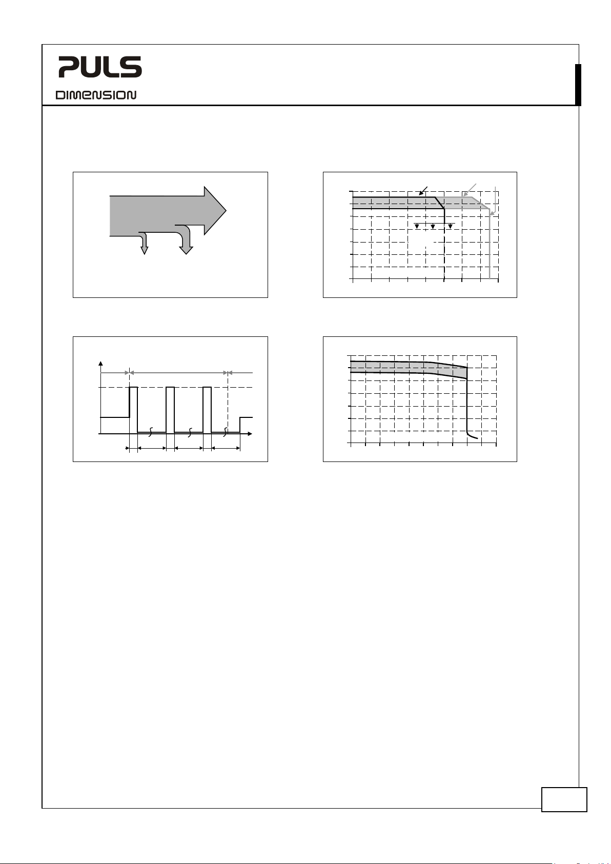
Fig. 4-6 Select an appropriate power supply,
which can deliver the additional current for
charging and internal consumption the DC-UPS
Fig. 4-8 Battery mod e: Hiccup
a short-circuit on output, typ.
PLUS
behavior during
24V, 20A, DC-UPS
Fig. 4-7 Battery mod e:
Output voltage vs. output current, typ.
Fig. 4-9 Battery mod e:
Dynamic peak current behavior, typ.
Aug. 2019 / Rev. 2.2 DS-UB20.241-EN
All parameters are specified at 24V, 20A output current, 25°C ambient and after a 5 minutes run-in time unless otherwise noted.
9/31
Page 10
UB20.241
UB
5. B
Setting of battery size selector
Allowed battery sizes
Battery
Battery charging current
End
typ.
26.5V
26.5V
center-tap not connected,
Temperature range for wh
the charging process is enabled
-Series
24V, 20A, DC-UPS
ATTERIES AND BATTERY CHARGING
The battery is not included in the DC-UPS. Use one of the PULS 24V battery modules (see chapter 22.4 and 22.5). In
addition to the PULS battery modules, the UB20.241 is also designed to be compatible with a large variety of different
VRLA (Valve Regulated Lead Acid) or SLA (Sealed Lead Acid) batteries from various suppliers.
The battery is one of the most important parts of a DC-UPS system, which needs to be carefully selected while also
paying close attention to storage, charging and environmental conditions. Select the proper size (capacity) according
to the required buffer time (see chapter 6) and the lifetime requirements (see chapter 23.1).
Batteries are service parts and need to be replaced periodically or when the internal battery tests of the DC-UPS
reports a random failure. Information regarding the DC-UPS battery tests and the replacement requirements can be
found in chapter 23.1.
The wiring from the battery to the DC-UPS must follow the instructions in chapter 3. Be aware that the current from
the battery to the DC-UPS can be higher than the load current due to the buffer voltage transformation, which
restores the battery voltage to a constant buffer voltage.
The UB20.241 has a battery size selector included, which allows an optimal use of small and large battery sizes.
It is not recommended to connect multiple batteries or battery modules in parallel. Chose larger sized battery instead.
Charging:
The UB20 comprises a constant current / constant voltage (CC-CV) charging method.
When the center-tap connection is installed, both 12V batteries are charged individually with their own charger. The
center-tap connection is optional and if not installed, both batteries will be charged with one common charging
voltage. The UB20 automatically recognizes if the center-tap connection is present or not.
When charging is approximately 85% completed, the individual green “Ready” LED for the specific battery stops
flashing and is on solid.
During charging, the DC-UPS consumes additional current from the input. The supplying power supply must be able to
deliver the additional required internal current consumption (including the charging current) specified as input current
in the table of chapter 4.
When the temperature sensor is installed, the end-of-charge-voltage is temperature compensated. The UB20
automatically recognizes if a temperature sensor is connected or not. In case no temperature sensor is installed, the
end-of-charge-voltage is fixed to a value which corresponds to a battery temperature of 40°C.
Use a PT1000 temperature sensor or the PULS UZK24 battery modules, which have this sensor already included. A list
of suitable PT1000 temperature sensors from different vendors can be provided.
nom. 3.9Ah – 10Ah
small battery
< 10Ah
5)
large battery
> 10Ah
10Ah – 150Ah
voltage nom. 24V 24V 2x 12V batteries in series
typ. 1.5A 3A In constant current mode
-of-charge-voltage typ. 2 x13.25V 2 x13.25V center-tap connected,
no temperature sensor connected
no temperature sensor connected
typ. 2x 13.1 to 14.2V
1)
2x 13.1 to 14.2V
1)
center-tap connected,
temperature sensor connected
typ. 26.2V to 28.4V
1)
26.2V to 28.4V
1)
center-tap not connected,
temperature sensor connected
ich
nom. -10°C to +50°C
2)
-40°C to +50°C
2)
Footnotes can be found on the next page.
Aug. 2019 / Rev. 2.2 DS-UB20.241-EN
All parameters are specified at 24V, 20A output current, 25°C ambient and after a 5 minutes run-in time unless otherwise noted.
10/31
Page 11
UB20.241
UB
Setting of battery size selector
-
Deep
Required
to allow charging
min.
14V
14V
center-tap not connected
Battery charging time
Battery discharge current
24V, 20A, DC-UPS
ctd.
-Series
small battery
< 10Ah
large battery
> 10Ah
-discharge protection typ. 10.5V / 9.0V 10.5V / 9.0V At 0A / 20A buffer current,
center-tap connected,
Buffering stops as soon as one battery
falls below this value.
typ. 21V / 18V 21V / 18V At 0A / 20A buffer current,
center-tap not connected
min. battery voltage
3)
max. 4h 40mins
min. 2 x 7V 2 x 7V center-tap connected
4)
- for a 7Ah battery
max. 8h
max. 44h
max. 94h
4)
4h
4)
22h
4)
47h
4)
for a 12Ah battery
4)
for a 65Ah battery
4)
for a 140Ah battery
typ. 170mA 170mA in battery mode at no output current
1) The end-of-charge voltage depends on the battery temperature. At 20°C the end-of-charge voltage is set to 13.6V (rsp. 27.2V) and
changes with -18mV/°C for 12V batteries and -36mV/°C for 24V batteries but not higher than 14.2V rsp. 28.4V.
2) Corresponds to the temperature readings of the external temperature sensor of the battery and is not the surrounding air temperature
of the DC-UPS. Frequent charging below +5°C (41°F) reduced the lifetime of the battery and should be avoided. Low temperatures
increase the battery impedance and also change the battery characteristics. This could result in a false “replace battery” signal or a
une
xpected interruption of a buffer event, especially with small batteries. To avoid this, the temperature range for charging is limited at
low temperatures depending on the battery size. If the end application requires temperatures below +5°C, it is recommended to use
batteries >10Ah.
3) Below this voltage level, charging does not start and the DC-UPS reports “check wiring”.
4) The listed charging time applies for a complete discharged battery until the DC-UPS indicated “Ready” with the green status LED. In
practice, the charging time can be much shorter, since the battery is usually not completely discharged. A very long charging time is m
ikely caused by a defective or old battery.
l
5) Batteries smaller than 6Ah are only recommended when the load current is below 10A.
n
ost
Aug. 2019 / Rev. 2.2 DS-UB20.241-EN
All parameters are specified at 24V, 20A output current, 25°C ambient and after a 5 minutes run-in time unless otherwise noted.
11/31
Page 12
UB20.241
UB
6. B
Battery size
Buffer
typ.
2h : 32m : 0s
5h : 17m : 59s
11h : 27m : 30s
Battery size
Buffer
15A
Battery
Charge
100%
80-90%
"Ready" signal threshold
t
t
Battery
Mode
Buffer Time
-Series
24V, 20A, DC-UPS
UFFER TIME
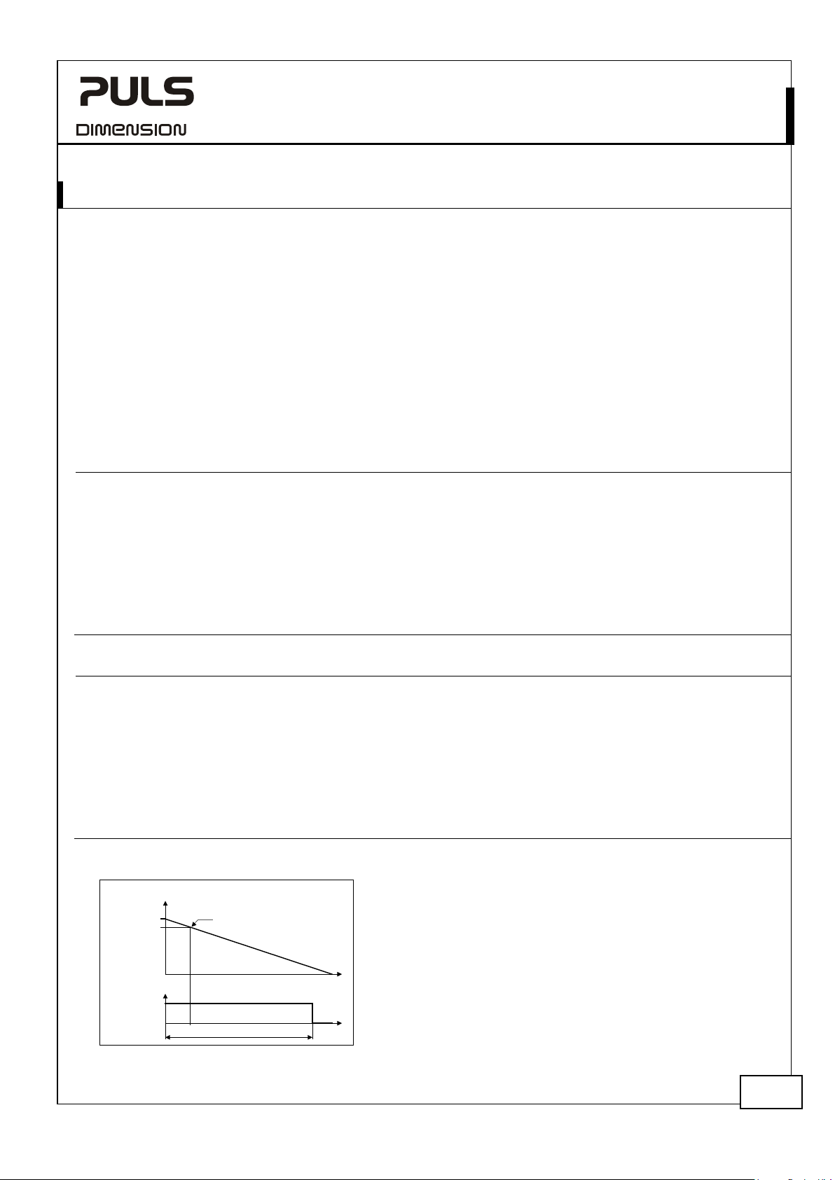
The buffer time (sometimes also called autonomy time) is the maximum period of time for which the battery can
maintain the required output current. The buffer time mainly depends on the capacity and quality of the battery and
the output current in battery mode.
The following times are typical values for a new product and the aging effect during operation is not included.
Pay attention:
- The following buffer times apply for a battery temperature between 20°C and 30°C and a buffer voltage setting of
22.5V. At higher voltages, the buffer time is correspondingly shorter. Furthermore, with a wire length of 2x1m
(equal 1m cord length) and a cross section of 4mm
- Due to long-term aging effects of batteries consider a buffer time reduction of 30-50% over time.
- The shown buffer times only apply for PULS battery modules or from PULS recommended batteries.
- The buffer time is defined for a fully charged battery. The buffer time can be 10-20% shorter for buffer events,
which start immediately after the “Ready” signal becomes active.
7Ah
(UZK24.071)
time typ. 1d : 17h : 40m : 0s 2d : 22h : 50m : 0s 6d : 19h : 53m : 20s
typ. 17h : 13m : 20s 1d : 6h : 41m : 40s 2d : 20h : 03m : 20s
typ. 5h : 16m : 40s 9h : 51m : 40s 21h : 43m : 20s
typ. 46m : 30s 2h : 2m : 55s 4h : 26m : 40s
typ. 19m : 11s 46m : 2s 2h : 10m : 0s
typ. 10m : 35s 27m : 34s 1h : 17m : 40s
typ. 06m : 45s 16m : 47s 55m : 00s
typ. 4s 4s 4s At 22.5V, 30A
2
(or AWG 12) between the battery module and the DC-UPS.
12Ah
(UZK24.121)
26Ah
At 22.5V, 0A
At 22.5V, 0.2A
At 22.5V, 1A
At 22.5V, 2A
At 22.5V, 5A
At 22.5V, 10A
At 22.5V, 15A
At 22.5V, 20A
65Ah 100Ah 140Ah
time typ. 16d : 10h : 26m : 40s 24d : 7h : 20m : 0s 34d : 17h : 20m : 0s At 22.5V, 0A
typ. 7d : 0h : 3m : 20s 10d : 17h : 05m : 0s 14d : 11h : 13m : 20s At 22.5V, 0.2A
typ. 2d : 4h : 21m : 40s 3d : 11h : 20m : 0s 4d : 21h : 21m : 40s At 22.5V, 1A
typ. 1d : 6h : 8m : 20s 1d : 22h : 30m : 0s 2d : 17h : 6m : 40s At 22.5V, 2A
typ. 11h : 56m : 40s 18h : 30m : 40s 1d : 1h : 55m : 0s At 22.5V, 5A
typ. 5h : 50m : 15s 9h : 11m : 40s 12h : 52m : 36s At 22.5V, 10A
typ. 3h : 49m : 17s 6h : 3m : 0s 8h : 27m : 44s At 22.5V,
typ. 2h : 49m : 29s 4h : 31m : 0s 6h : 19m : 29s At 22.5V, 20A
typ. 4s 4s 4s At 22.5V, 30A
Fig. 6-1 Buffer time definition
Aug. 2019 / Rev. 2.2 DS-UB20.241-EN
All parameters are specified at 24V, 20A output current, 25°C ambient and after a 5 minutes run-in time unless otherwise noted.
12/31
Page 13
UB20.241
UB
Buffer Time
10A
12A
14A
16A
18A
20A
6A
8A
4A
2A
0A
Buffer Current
20 30100 60 705040 9080
Minutes
B
1,5
3 52 8 1076
Hours
4 9
Batteries:
A... 7Ah (UZK24.071)
B... 12Ah (UZK24.121)
A
A
B
10A
12A
14A
16A
18A
20A
6A
8A
4A
2A
0A
Buffer Current
2 310 6 754 10 1198 14 151312 18 191716 20 hours
Buffer Time
A
Batteries:
A... 7Ah
B... 12Ah
C... 26Ah
D... 65Ah
E... 100Ah
F... 140Ah
B
C
D
E
F
-Series
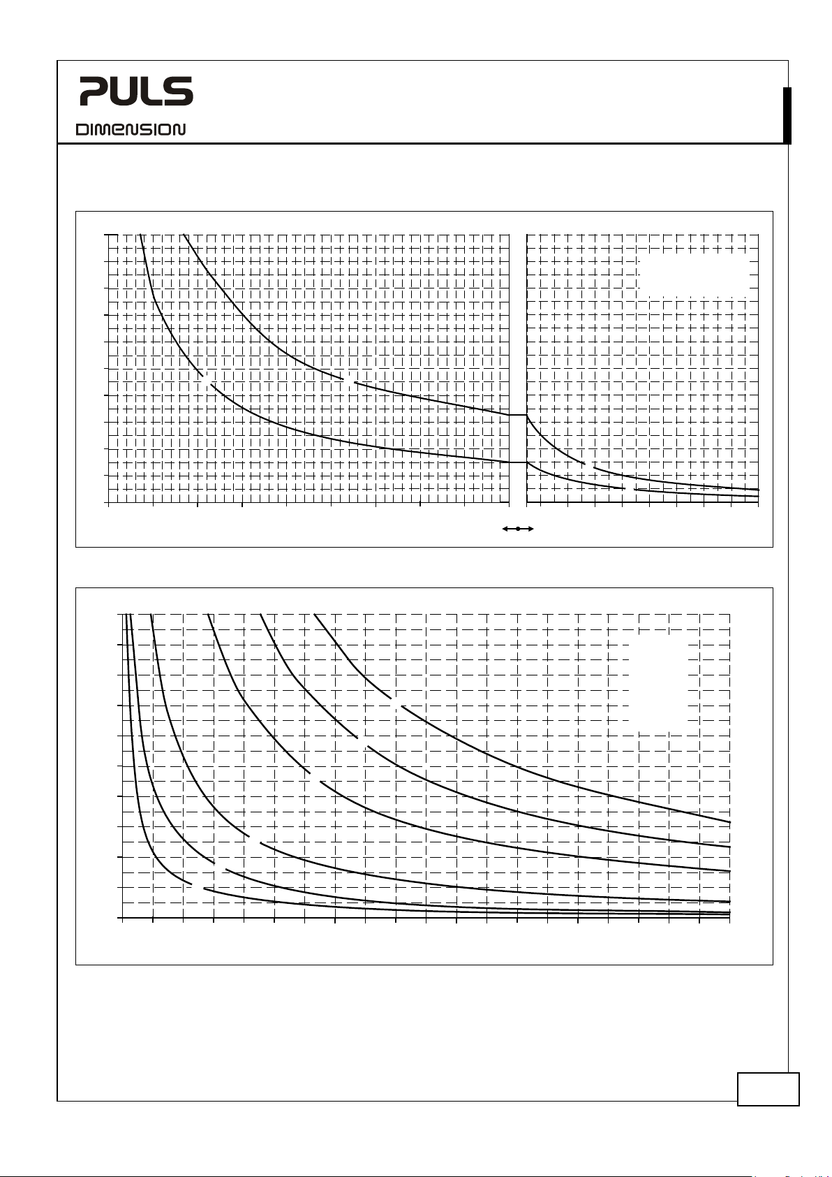
Fig. 6-2 Buffer time curves for battery modules UZK24.071 and UZK24.121, typ.
24V, 20A, DC-UPS
Fig. 6-3 Buffer time curves for various battery sizes, typ.
Aug. 2019 / Rev. 2.2 DS-UB20.241-EN
All parameters are specified at 24V, 20A output current, 25°C ambient and after a 5 minutes run-in time unless otherwise noted.
13/31
Page 14
UB20.241
UB
7. R
Contact ratings
max.
60Vdc 0.3A, 30Vdc 1A, 30Vac 0.5A
resistive load
Isolation voltage
Contact ratings
Isolation voltage
8. R
Contact ratings
max.
60Vdc 0.3A, 30Vdc 1A, 30Vac 0.5A
resistive load
Isolation voltage
9. I
Signal voltage
Signal current
Inhibit threshold
Isolation voltage
7
+
5.1V
3mA
Inhibit
8
-
-Series
24V, 20A, DC-UPS
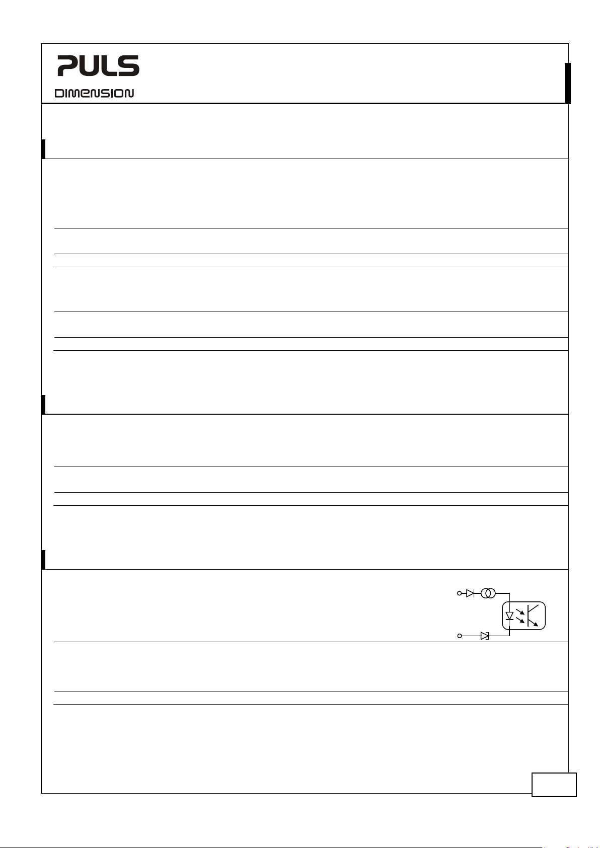
EADY AND BUFFERING RELAY CONTACT
The DC-UPS is equipped with two independent relay contacts for remote monitoring and controlling of the unit.
Ready contact
Contact is closed when both batteries are charged more than typical 85%, no wiring failure is detected, input voltage
is sufficient and inhibit signal is not active.
min. 1mA at 5Vdc min. permissible load
see chapter 19.
Buffering contact
Contact is closed when unit is in battery mode.
max. 60Vdc 0.3A, 30Vdc 1A, 30Vac 0.5A resistive load
min. 1mA at 5Vdc min. permissible load
see chapter 19.
EPLACE BATTERY RELAY CONTACT
The contact is closed when one of the battery quality tests of at least one battery reports a negative result.
To reset the “replace battery” signal, cycle the input power. The battery that has failed is indicated by the green LED
which is off. The battery should be replaced as soon as possible.
min. 1mA at 5Vdc min. permissible load
see chapter 19.
NHIBIT INPUT
The inhibit input disables buffering. In power supply mode, a static signal is required. In
battery mode, a pulse with a minimum length of 250ms is required to stop buffering. See
chapter 23.8 for details.
max. 35Vdc
max. 6mA, current limited
min.
max.
see chapter 19.
6Vdc, buffering is disabled above this threshold level
10Vdc
Aug. 2019 / Rev. 2.2 DS-UB20.241-EN
All parameters are specified at 24V, 20A output current, 25°C ambient and after a 5 minutes run-in time unless otherwise noted.
14/31
Page 15
UB20.241
UB
10. E
Efficiency
Power losses
11. L
MTBF
Calculated lifetime expectancy
MTBF
MTBF
(Ground benign)
MTBF
(Ground fixed)
-Series
FFICIENCY AND POWER LOSSES
typ. 99% Power supply mode, 20A output current,
batteries fully charged
typ. 1.9W Power supply mode, 0A output current,
batteries fully charged
typ. 4.8W Power supply mode, 0A output current,
during charging batteries < 10Ah
typ. 6.8W Power supply mode, 0A output current,
during charging batteries > 10Ah
typ. 4.6W Power supply mode, 20A output current,
batteries fully charged
typ. 4.2W Battery mode, 0A output current
typ. 7.6W Battery mode, 10A output current
typ. 21.3W Battery mode, 20A output current
24V, 20A, DC-UPS
IFETIME EXPECTANCY AND
*)
440 000h*) Power supply mode, 10A and 40°C
1 244 000h*) Power supply mode, 10A and 25°C
122 000h*) Power supply mode, 20A and 40°C
**)
SN 29500, IEC 61709 649 000h Power supply mode, 20A and 40°C
**)
MIL HDBK 217F 372 000h Power supply mode, 20A and 40°C; Ground Benign GB40
**)
MIL HDBK 217F 107 000h Power supply mode, 20A and 40°C; Ground Fixed GF40
*) The calculated lifetime expectancy shown in the table indicates the minimum operating hours (service life) and is determined by the
lifetime expectancy of the built-in electrolytic capacitors. Lifetime expectancy is specified in operational hours and is calculated according
to the capacitor’s manufacturer specification. The manufacturer of the electrolytic capacitors only guarantees a maximum life of up to 15
years (131 400h). Any number exceeding this value is a calculated theoretical lifetime which can be used to compare devices.
**) MTBF stands for Mean Time Between Failure, which is calculated according to statistical device failures, and indicates reliability of a
device. It is the statistical representation of the likelihood of a unit to fail and does not necessarily represent the life of a product.
The MTBF figure is a statistical representation of the likelihood of a device to fail. A MTBF figure of e.g. 1 000 000h means that
statistically one unit will fail every 100 hours if 10 000 units are installed in the field. However, it can not be determined if the failed unit
has been running for 50 000h or only for 100h.
498 000h Power supply mode, 20A and 25°C; Ground Benign GB25
137 000h Power supply mode, 20A and 25°C; Ground Fixed GF25
345 000h Power supply mode, 20A and 25°C
1 097 000h Power supply mode, 20A and 25°C
Aug. 2019 / Rev. 2.2 DS-UB20.241-EN
All parameters are specified at 24V, 20A output current, 25°C ambient and after a 5 minutes run-in time unless otherwise noted.
15/31
Page 16
UB20.241
UB
12. F
-
+
DC- UPS
24V
Power
Supply
Buck/Boost
Converter
Battery
Charger
1
Battery
Diagnosis
1
+
-
24V
Battery
+
-
Input
Batt
+ -
BAT2
12V
+ -
BAT1
12V
CT
Battery
Charger
2
Current
Limiter
Battery
Diagnosis
2
(13)
-
Current
Measure-
ment
+
-
Buffered
Load
Output
Diagnosis LED
(yellow)
Status LED
Batt 2 (green)
Inhibit +
Controller
Error LED
(red)
Replace Battery
Buffering
Contact
Ready Contact
Buffer Time Limiter
10s, 30s, 1m, 3m, 10m,
(7)
Inhibit -
(8)
(1)
(2)
(3)
(4)
(5)
(6)
Status LED
Batt 1 (green)
Buffer Voltage
22.5V, 24V, 25V, 26V
Temp. Sensor (11)
Center
Tap
Back
Feeding
Protection
Battery Size Selector
<10Ah / > 10Ah
Temp. Sensor (12)
Batt
13. T
Type
Solid wire
Stranded wire
American Wire Gauge
Max. wire diameter
Wire stripping length
Tightening torque
Screwdriver
Instructions:
a)
b)
c)
d)
e)
-Series
UNCTIONAL DIAGRAM
24V, 20A, DC-UPS
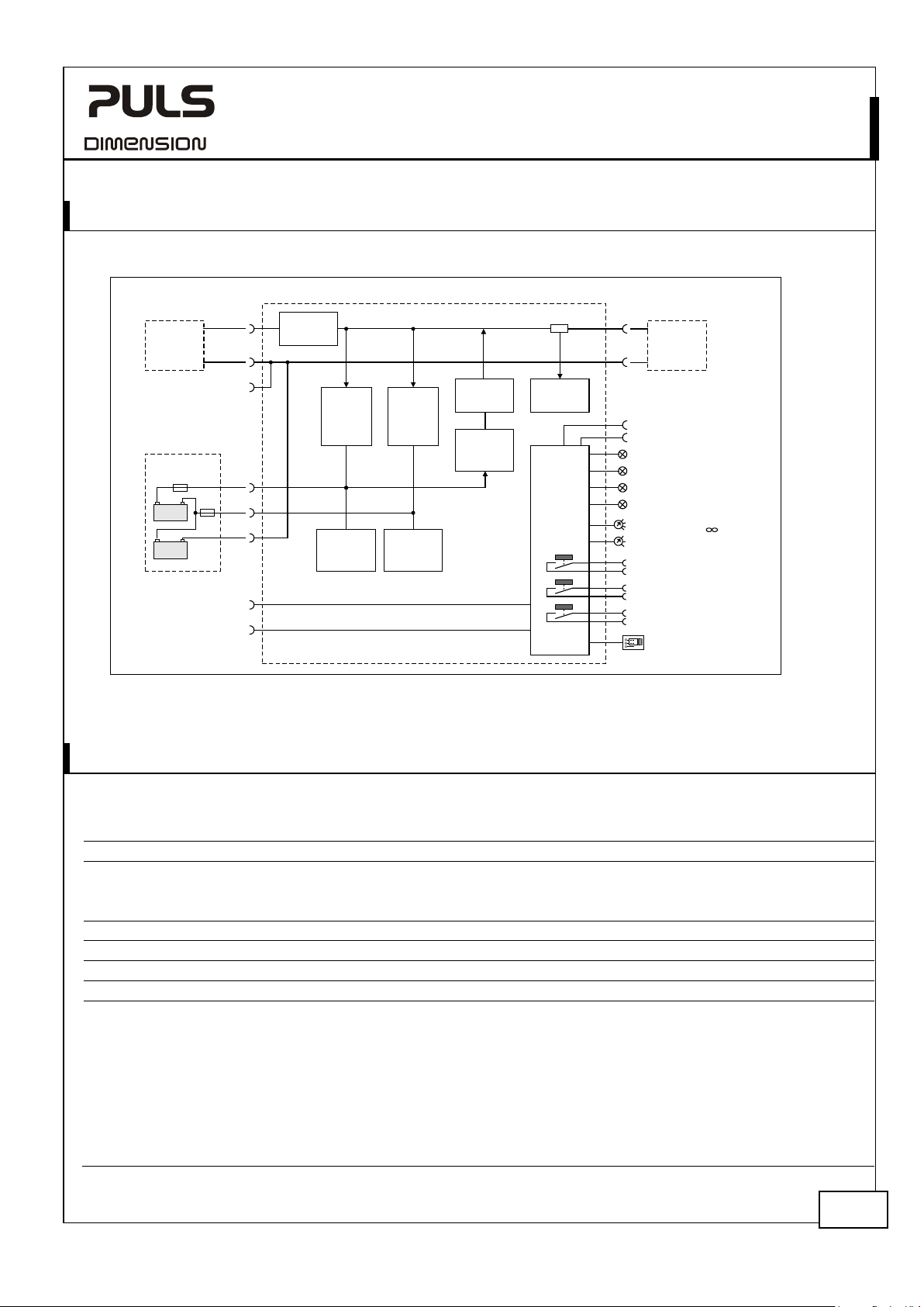
Fig. 12-1 Functional diagram
The terminals are IP20 finger safe constructed and suitable for field and factory wiring.
Use appropriate copper cables that are designed for minimum operating temperatures of:
60°C for ambient up to 45°C and
75°C for ambient up to 60°C and
90°C for ambient up to 70°C minimum.
Follow national installation codes and installation regulations!
Ensure that all strands of a stranded wire enter the terminal connection!
Unused terminal compartments should be securely tightened or closed.
Ferrules are allowed.
Aug. 2019 / Rev. 2.2 DS-UB20.241-EN
All parameters are specified at 24V, 20A output current, 25°C ambient and after a 5 minutes run-in time unless otherwise noted.
ERMINALS AND WIRING
Input and output Signals
screw terminals pluggable screw terminals
0.5-6mm2 0.2-1.5mm2
0.5-4mm2 0.2-1.5mm2
AWG 20-10 AWG 22-14
3.5mm slotted or cross-head No 2 3mm slotted
2.8mm (including ferrules) 1.5mm (including ferrules)
7mm / 0.28inch 6mm / 0.25inch
1Nm / 9lb.inch 0.4Nm / 3.5lb.inch
16/31
Page 17
UB20.241
UB
14. F
-Series
RONT SIDE AND USER ELEMENTS
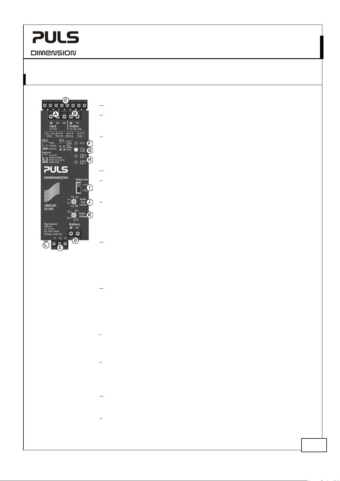
Fig. 14-1 Front side
A Input Terminal (screw terminal)
B Output Terminal (screw terminal) One extra (-) pole for easy grounding.
The minus-pole is internally hard-wired with the minus-pole of the input and battery
terminals.
C Signal Connector (8-pole plug connector) comprises the following connections:
- Ready relay contact, see chapter 7.
- Buffering relay contact, see chapter 7.
- Inhibit input signal, see chapter 9 and chapter 23.8.
- Replace battery, see chapter 5 and 8.
D Battery Terminal (screw terminal)
E Battery Monitoring Connector (3-pole plug connector)
- Connection for temperature sensor for battery temperature. See chapter 5 (optional).
- “Center-Tap” connection - middle point of the two batteries See chapter 3 (optional).
F Red Error LED – This LED indicates that charging or buffering is not possible. The
flashing pattern reports the following reasons:
- Check wiring
- Insufficient input voltage
- Too high temperatures
For details see
G Yellow Diagnosis LED – This LED helps troubleshooting and the flashing pattern
indicates the following:
- Output overloaded (current)
- Battery replacement required
- Expired buffer time due to buffer time selector or discharged battery
- Activated inhibit input
For details see
H Green Status LED – Each battery has its own status LED. Battery 1 represents the
battery, which is electrically closer to the (+) pole and battery 2, which is closer
to the (-) pole. The flashing pattern of this LED reports the following information:
- Ready
- Charging
- Buffering
For details see
I Battery Size Selector (pluggable jumper) - For details see chapter 5
Two positions to select battery sizes > and <10Ah. Influences the charging current, the
allowed battery temperature range and the battery quality tests. Factory set: <10Ah.
A missing jumper equals a <10Ah setting.
J Buffer Time Limiter (rotary switch with 6 dents) - For details see chapter 6.
Limits the maximum buffer time in a buffer event to save battery energy. Selectable
between 10s 30s, 60s, 3 minutes and 10 minutes. If no limitation is selected (infinite
period of time), the buffering will be ended by the deep discharge protection.
Factory set: infinite.
K Buffer Voltage Selector (rotary switch with 4 dents) - For details see chapter 4.
Allows setting the output voltage in battery mode to 22.5V, 24V, 25V or 26V.
Factory set: 22.5V
L Chassis Ground (screw)
Use a M4 ring-type terminal to connect the housing to ground, when required.
Fig. 14-4.
Fig. 14-3.
Fig. 14-2.
24V, 20A, DC-UPS
.
Aug. 2019 / Rev. 2.2 DS-UB20.241-EN
All parameters are specified at 24V, 20A output current, 25°C ambient and after a 5 minutes run-in time unless otherwise noted.
17/31
Page 18
UB20.241
UB
1
0
Ready
1
0
Charging
1
0
Buffering
10
Hz
1
0
Overload
1
0
Replace
Battery
1
0
Buffertime
expired
1
0
Inhibit
active
5
Hz
1
0
Check
Wir
ing
1
0
Input
Voltage
1
0
Temp.
-Series
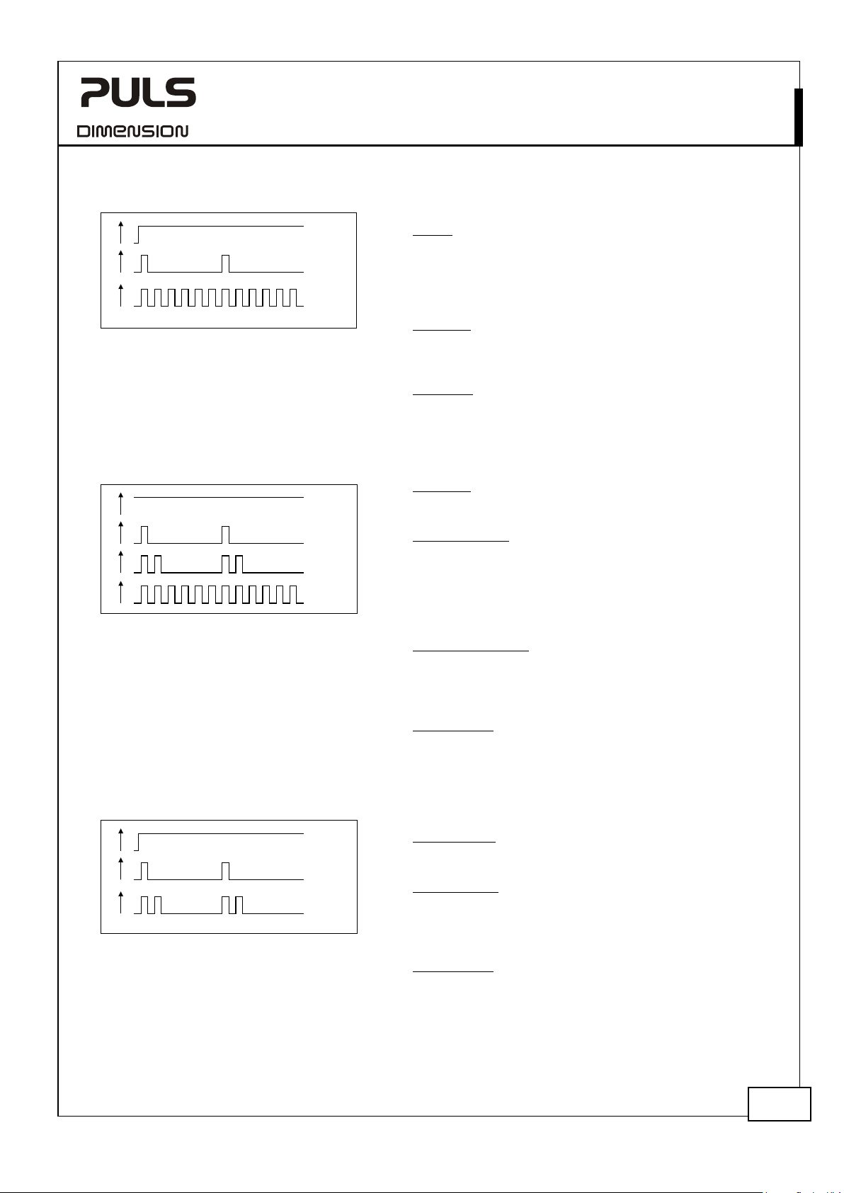
ig. 14-2
Flashing pattern for green “Status LED”
Flashing pattern for yellow “Diagnoses LED”
F
ig. 14-3
F
24V, 20A, DC-UPS
Each battery has its own status LED. The signals are the
same for both batteries.
Ready:
The LEDs are on solid when the battery is charged (> 85%),
no wiring failure is recognized, input voltage is sufficient.
After the unit is turned-on with charged batteries, it can
take 20s or longer that the signal switches from charging
to ready.
Charging:
The LEDs are flashing with a low frequency when the
batteries are charging and the state-of-charge is below
85%.
Buffering:
The LEDs are flashing with a high frequency when the unit
is in battery mode.
This LED helps troubleshooting.
Overload:
The LED is on solid when the output current is permanently
above 20A in battery mode or 25A in power supply mode.
Replace Battery:
The LED is flashing with a low frequency when one battery
has failed the periodically performed battery quality test.
In case the center-tap connection is present, the battery
that has failed is indicated by the green LED which is off.
Otherwise, both LEDs are off. The battery should be
replaced as soon as possible.
Buffertime expired:
The LED is double flashing when the output has switched
off due to the setting of the buffer-time limiter or
discharged battery. This signal will be displayed for 15
minutes after the output has switched off.
Inhibit active:
The LED is flashing with a high frequency when buffering
is disabled due to an active inhibit signal.
ig. 14-4
Flashing pattern for red “Error LED”
F
This LED indicates that charging or buffering is not
possible.
Check Wiring:
The LED is on solid when a failure in the wiring, battery or
battery fuse is identified.
Input Voltage:
A single flash indicates that the input voltage is >30V or
the input voltage is too low for the adjusted buffer
voltage. The input voltage must be at least 1V higher than
the selected buffer voltage.
Temperature:
A double flash indicates that the temperature of the DCUPS is too high (> 70°C) or that the temperature of the
battery is too high (> 50°C) or too low (< -10°C in setting
<10Ah). Battery temperatures indications require a
connected battery temperature sensor.
Aug. 2019 / Rev. 2.2 DS-UB20.241-EN
All parameters are specified at 24V, 20A output current, 25°C ambient and after a 5 minutes run-in time unless otherwise noted.
18/31
Page 19
UB20.241
UB
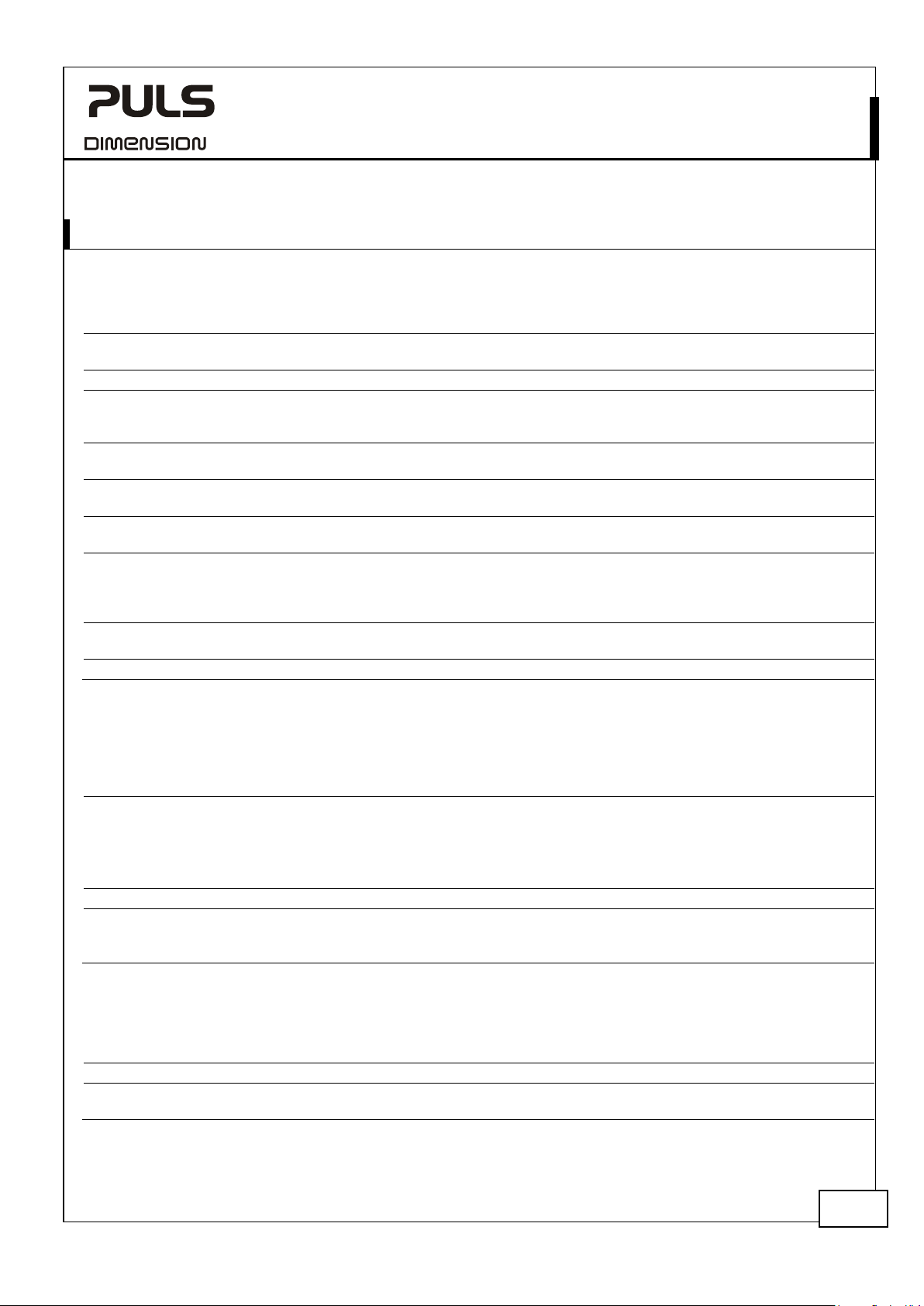
15. EMC
EMC Immunity
Electrostatic discharge
E
Fast transients (Burst)
Surge voltage on input
EN 61000-4-5
+ -
1kV
Criterion A
Surge voltage on output
Surge voltage on
and center
Surge
input, ready
and replace battery
contacts
Surge voltage on
temperature sensor
Conducted disturbance
EMC Emission
Conducted emission
Radiated emission
This device complies with FCC Part 15 rules.
Operation is subjected to following two conditions: (1) this device may not cause ha
device must accept any interference received, including interference that may cause undesired operation.
Switching Frequency
100kHz
Buck-boost converter and battery charger
8kV
15kV
2kV
2kV
2kV
2kV
1kV
2kV
- ***)
1kV
24V, 20A, DC-UPS
Criterion A
Criterion A
Criterion A
Criterion A
Criterion A
Criterion A
Criterion A
Criterion A
Criterion A
Criterion A
-Series
The DC-UPS is suitable for applications in industrial environment as well as in residential, commercial and light industry
environment without any restrictions.
All tests are performed in power supply and battery mode.
lectromagnetic RF field EN 61000-4-3 80MHz-2.7GHz 10V/m Criterion A
EN 61000-4-4 input lines
battery
-tap
voltage on inhibit
-, buffering
According generic standards: EN 61000-6-1 and EN 61000-6-2
EN 61000-4-2 contact discharge *)
air discharge *)
output lines
signals **)
+ / - chassis ground
EN 61000-4-5 + -
+ / - chassis ground
EN 61000-4-5 + -
+ / - chassis ground
EN 61000-4-5 signals chassis ground 1kV Criterion A
EN 61000-4-5 signals chassis ground 1kV Criterion A
EN 61000-4-6 0.15-80MHz 10V Criterion A
*) Chassis ground connection earthed (grounded)
**) Tested with coupling clamp
***) Not relevant due to short wire length
Criterions:
A: DC-UPS shows normal operation behavior within the defined limits.
IEC/CISPR 16-1-2, IEC/CISPR 16-2-1 input lines limits for DC power ports acc.
EN 55011, EN 55022 Class B
***) Not relevant due to short wire length
According generic standards: EN 61000-6-3 and EN 61000-6-4
IEC/CISPR 16-1-2, IEC/CISPR 16-2-1 output lines limits for DC power ports acc.
IEC/CISPR 16-1-2, IEC/CISPR 16-2-1 battery lines -
The DC-UPS has four converters included, three operate with the same switching
frequency.
EN 61000-6-3 fulfilled
EN 61000-6-3 fulfilled
***)
rmful interference, and (2) this
45 to 80kHz Auxiliary converter,
switching frequency is input voltage dependent
Aug. 2019 / Rev. 2.2 DS-UB20.241-EN
All parameters are specified at 24V, 20A output current, 25°C ambient and after a 5 minutes run-in time unless otherwise noted.
19/31
Page 20
UB20.241
UB
16. E
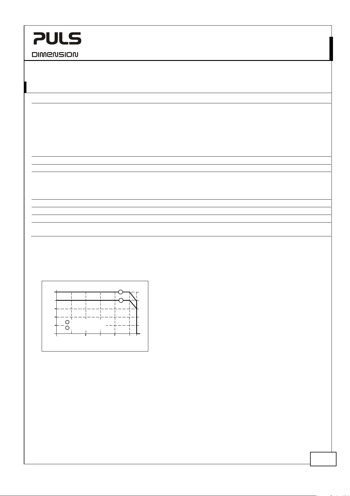
Operational temperature
Derating
2.5%/°C
+60°C to +70°C (140°F to 158°F)
Storage temperature
Humidity
Vibration sinusoidal
2-17.8Hz: ±1.6mm; 17.8-500Hz: 2g
IEC 60068-2-6
Shock
Altitude
Over
Degree of pollution
LABS compatibility
use in paint shops.
0
-40 0 40
60
5
10
15
20
25A
Ambient Temperature
70°C
a
b
Power Supply Mode
Battery Mode
a
b
20-20
Allowable Continuous Output Current
-Series
24V, 20A, DC-UPS
NVIRONMENT
*) -40°C to +70°C (-40°F to 158°F) Reduce continuous output current according
Fig. 16-1.
The operational temperature range can be
reduced by the battery specification. The DCUPS includes some safety features which
reduce the temperature range for charging.
See chapter 5 for details.
-40 to +70°C (-40°F to 158°F) For storage and transportation
**) 5 to 95% r.H. IEC 60068-2-30
2 hours / axis
30g 6ms, 20g 11ms
***)
3 bumps / direction, 18 bumps in total
0 to 6000m (0 to 20 000ft) Approvals apply only up to 2000m
-voltage category II IEC 62103, EN 50178, EN 60950, UL 840
2 IEC 62103, EN 50178, not conductive
The unit does not release any silicone or other LABS-critical substances and is suitable for
***)
IEC 60068-2-27
*) Operational temperature is the same as the ambient or surrounding temperature and is defined as the air temperature 2cm below the
unit.
**) Do not energize while condensation is present
***) Higher levels are allowed when using the wall mounting bracket ZM2.WALL
Fig. 16-1 Continuous output current vs.
ambient temp.
Aug. 2019 / Rev. 2.2 DS-UB20.241-EN
All parameters are specified at 24V, 20A output current, 25°C ambient and after a 5 minutes run-in time unless otherwise noted.
20/31
Page 21
UB20.241
UB
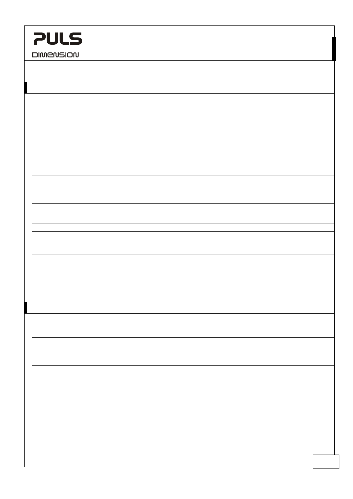
17. P
Output protection
Output over
Degree of protection
P
Over
Input over
Internal input fuse
Reverse input polarity protection
Reverse battery polarity protection
Protection against
Battery deep discharge protection
18. SAFETY FEATURES
Input / output separation
Output voltage
Class of protection
Isolation resistance
> 10MOhm
Touch current (leak
-Series
ROTECTION FEATURES
In power supply mode:
The DC-UPS is protected by the current limitation of the supplying power
supply or a circuit protector on the input in case the power supply has an
ampacity greater than 28A.
In battery mode:
The DC-UPS is electronically protected against overload, no-load and
short-circuits
-voltage protection typ. 32Vdc
max. 35Vdc
IP 20 EN/IEC 60529
enetration protection > 3.5mm E.g. screws, small parts
-temperature protection included for
battery mode
-voltage protection max. 35Vdc No harm or defect of the unit
no
included Max. -40V
included Max. -35Vdc
wrong battery voltage included Max. +35Vdc
included Buffering will stop when deep discharge protection is
In case of an internal DC-UPS defect, a redundant
circuit limits the maximum output voltage in battery
mode. The output shuts down and automatically
attempts to restart.
For use in a controlled environment according to CSA
22.2 No 107.1-01.
Output shuts down with automatic restart.
Additional temperature protection for charging of
batteries can be found in chapter 5.
active. Battery will be disconnected from the DC-UPS.
24V, 20A, DC-UPS
SELV IEC/EN 60950-1,
III PE (Protective Earth) connection not required
*) > 10MOhm
age current) The leakage current which is produced by the DC-UPS itself depends on the input
*) Center-tap terminal is categorized in the group of “power port”.
Aug. 2019 / Rev. 2.2 DS-UB20.241-EN
All parameters are specified at 24V, 20A output current, 25°C ambient and after a 5 minutes run-in time unless otherwise noted.
not provided The minus-pole is internally hard-wired with the minus-
pole of the input and battery terminals.
The input must be powered from a SELV power source.
PELV IEC/EN 60204-1, EN 50178, IEC 62103, IEC 60364-4-41,
The input must be powered from a PELV power source.
Power port to signal port
> 10MOhm
voltage ripple and need to be investigated in the final application. For a smooth DC
input voltage, the produced leakage current is less than 100μA.
Power port to housing
Signal port to housing
21/31
Page 22
UB20.241
UB
19. D
A B C
Input, Output,
Battery,
Temperature
Sensor,
Center-tap
Chassis
Signal Port
A
CB
20. A
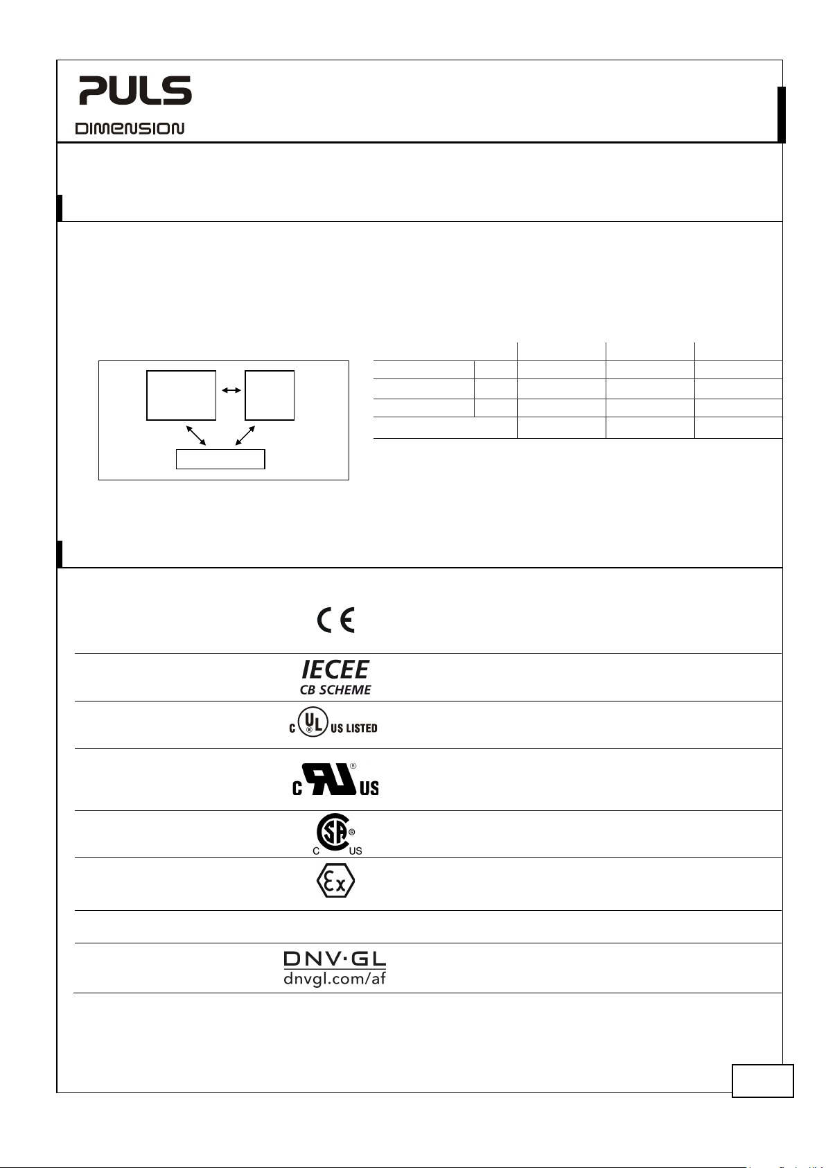
EC Declaration of Conformity
IEC 60950
2
UL 5
IND. CONT. EQ.
UL 60950
2
ANSI / IS
Class I Div 2
EN 60079-0, EN 60079-15
ATEX
Approval for use in hazardous locations Zone 2 Category 3G.
IEC 60079
IECEx
locations. Number of IECEx certificate: IECEx EPS 15.0049X
Marine
-Series
24V, 20A, DC-UPS
IELECTRIC STRENGTH
The signal port (relay contacts and inhibit input) are floating and separated from the power port (input voltage,
output voltage, center-tap terminal and temperature sensor).
Type and factory tests are conducted by the manufacturer. Field tests may be conducted in the field using the
appropriate test equipment which applies the voltage with a slow ramp (2s up and 2s down). Connect all poles of the
power port terminals together as well as all poles of the signal port before conducting the test. When testing, set the
cut-off current settings to the value in the table below. The following isolation tests were performed:
Fig. 19-1 Dielectric strength
Type test 60s 1060Vac 1060Vac 1060Vac
Factory test 5s 650Vac 650Vac 650Vac
Field test 5s 500Vac 500Vac 500Vac
Cut-off current setting > 90mA > 1mA > 1mA
PPROVALS
nd
nd
-1
Edition
08
-1
Edition
A 12.12.01-2013
I 3G Ex nA nC II T4 Gc
I
-0, IEC 60079-15
Germanischer Lloyd classified
The CE mark indicates conformance with the
- EMC directive 2004/108/EC,
- Low-voltage directive (LVD) 2006/95/EC and the
- RoHS directive 2011/65/EU.
CB Scheme,
Information Technology Equipment
Applicable for altitudes up to 2000m.
Listed for use as Industrial Control Equipment;
U.S.A. (UL 508) and Canada (C22.2 No. 107-1-01);
E-File: E198865
Recognized for use as Information Technology Equipment,
Level 5; U.S.A. (UL 60950-1) and Canada (C22.2 No. 60950-1);
E-File: E137006
Applicable for altitudes up to 2000m.
Recognized for use in Hazardous Location Class I Div 2 T4
Groups A,B,C,D systems; U.S.A. (ANSI / ISA 12.12.01-2013)
and Canada (C22.2 No. 213-M1987)
Number of ATEX certificate: EPS 15 ATEX 1 025 X
The DC-UPS must be built-in in an IP54 enclosure.
Suitable for use in Class 1 Zone 2 Groups IIa, IIb and IIc
Environmental category: C, EMC2
Marine and offshore applications
Aug. 2019 / Rev. 2.2 DS-UB20.241-EN
All parameters are specified at 24V, 20A output current, 25°C ambient and after a 5 minutes run-in time unless otherwise noted.
22/31
Page 23
UB20.241
UB
21. P
Width
Height
Depth
Weight
DIN
Housing material
Installation clearances
-Series
24V, 20A, DC-UPS
HYSICAL DIMENSIONS AND WEIGHT
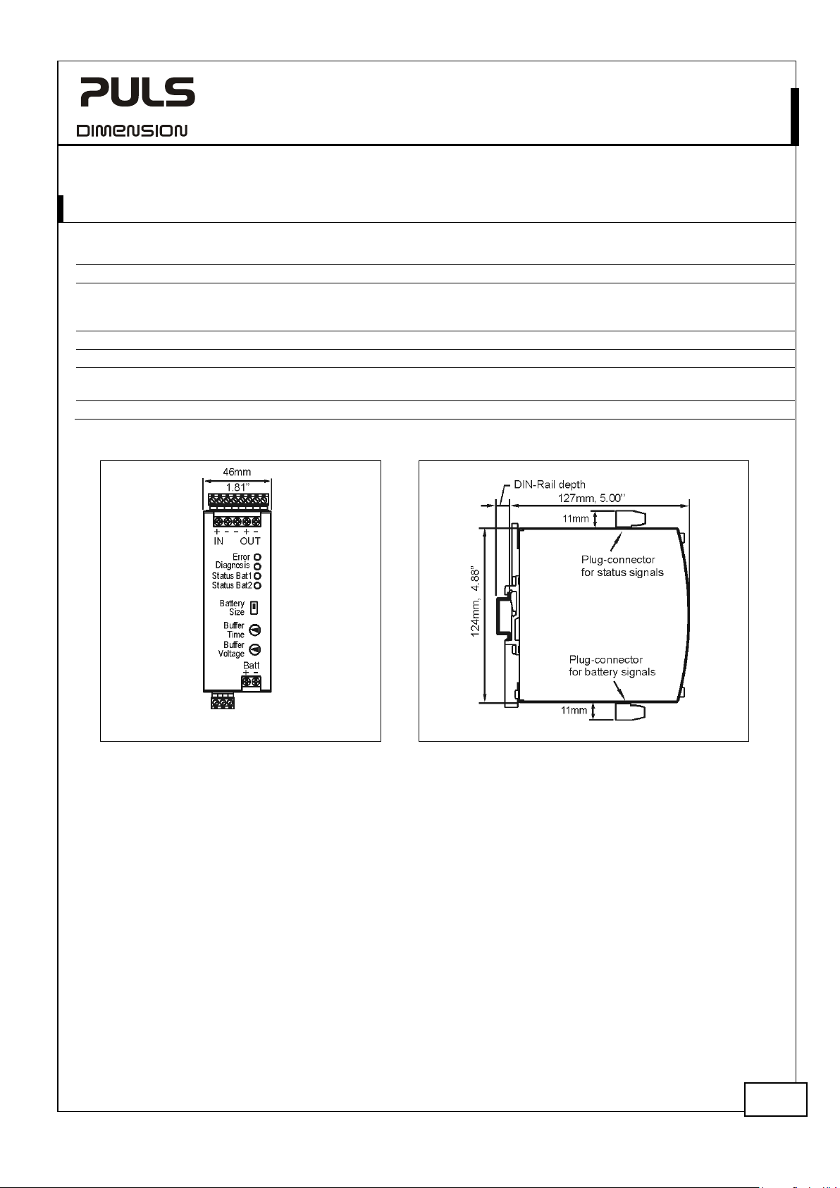
46mm 1.81’’
124mm 4.88’’
127mm 5.0’’
The DIN-rail height must be added to the unit depth to calculate the total required
installation depth.
700g / 1.54lb
-rail Use 35mm DIN-rails according to EN 60715 or EN 50022 with a height of 7.5 or 15mm.
Body: Aluminium alloy
Cover: zinc-plated steel
See chapter 2
Fig. 21-1 Front view Fig. 21-2 Side view
Aug. 2019 / Rev. 2.2 DS-UB20.241-EN
All parameters are specified at 24V, 20A output current, 25°C ambient and after a 5 minutes run-in time unless otherwise noted.
23/31
Page 24
UB20.241
UB
22. A
-Series
CCESSORIES
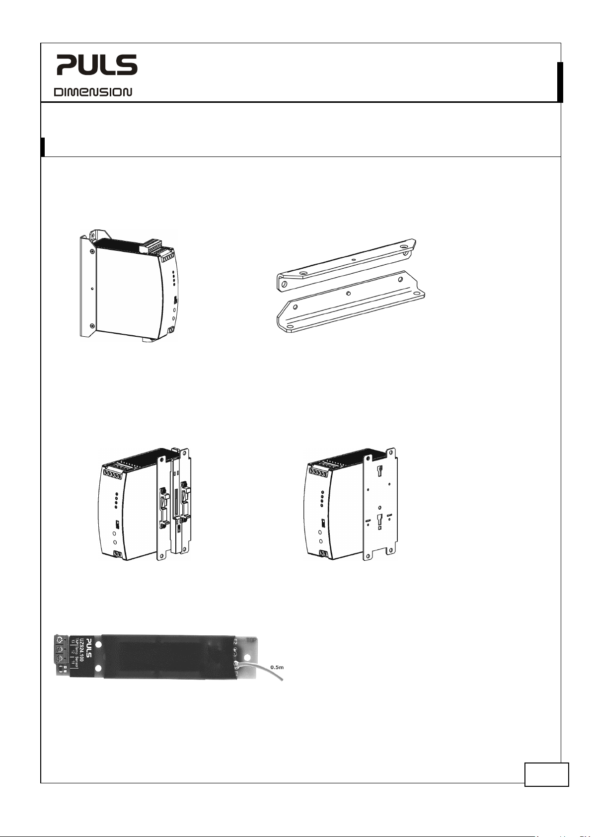
22.1. ZM2.WALL – WALL-MOUNTING BRACKET
This bracket is used to mount the DC-UPS onto a flat surface without utilizing a DIN-rail.
24V, 20A, DC-UPS
22.2. ZM12.SIDE – WALL-MOUNTING BRACKET
This bracket is used to mount DC-UPS sideways with or without utilizing a DIN-rail. The two aluminum brackets and
the black plastic slider of the unit have to be detached, so that the steel brackets can be mounted.
For sideway DIN-rail mounting, the removed aluminum brackets and the black plastic slider need to be mounted on
the steel bracket.
Side mounting with DIN-rail brackets Side mounting without DIN-rail brackets
22.3. UZS24.100 – SENSOR BOARD FOR DC-UPS
The UZS24.100 enables all the benefits of the PULS 1-BatteryConcept when using individual batteries and not one of the
UZK24 battery modules. This sensor board makes the use of
matched batteries unnecessary and allows a precise battery
charging and testing resulting in the longest possible battery
life. The sensor board contains a PT1000 temperature sensor
and an auto-resettable fuse which is suitable for charging currents up to 3.5A. The fuse protects the center-tap wire
between the battery module and the DC-UPS control unit.
Aug. 2019 / Rev. 2.2 DS-UB20.241-EN
All parameters are specified at 24V, 20A output current, 25°C ambient and after a 5 minutes run-in time unless otherwise noted.
24/31
Page 25
UB20.241
UB
Battery voltage
DC 24V
Battery capacity
Temperature sensor
PT1000
Dimensions WxHxD
Weight UZK24.
Battery voltage
DC 24V
Battery capacity
12Ah
Temperature sensor
Dimensions WxHxD
Weight UZK24.121 / UZO24.121
-Series
24V, 20A, DC-UPS
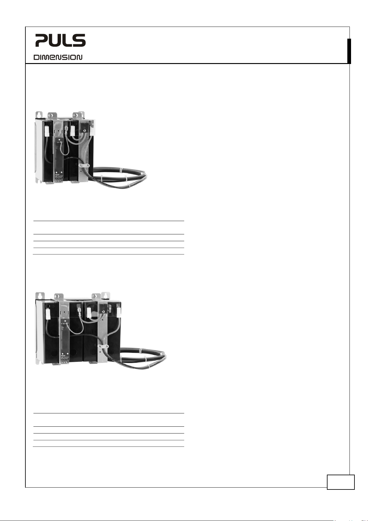
22.4. UZK24.071 – 24V, 7AH BATTERY MODULE
The UZK24.071 passive battery module utilizes two non-spillable 7Ah
maintenance-free lead-acid batteries (connected in series), that are
assembled in one package with all the required wiring included.
The battery module includes the monitoring and protection board
UZS24.100. This board contains a temperature sensor and a center-tap
connection with an auto-resettable fuse to protect the center-tap wire
between the battery module and the DC-UPS control unit. Connecting
the center-tap wire to the DC-UPS control unit enables all the benefits
of the PULS 1-Battery-Concept. This makes the use of matched
replacement batteries unnecessary and allows a precise battery charging
and testing which results in the longest possible battery life.
The UZK24 battery module is available in two different options. It can
be ordered with assembled batteries (UZK24.071) or as a battery bracket without batteries (UZO24.071), allowing for
different battery options. The mounting bracket option also allows the batteries to be assembled just in time, avoiding
outdated batteries due to limited shelf life.
7Ah
137x186x143mm
071 / UZO24.071 6000g / 800g
22.5. UZK24.121 – 24V, 12AH BATTERY MODULE
The UZK24.121 passive battery module utilizes two non-spillable
12Ah maintenance-free VRLA lead-acid batteries (connected in
series), that are assembled in one package with all the required
wiring included.
The battery module includes the monitoring and protection
board UZS24.100. This board contains a temperature sensor and
a center-tap connection with an auto-resettable fuse to protect
the center-tap wire between the battery module and the DC-UPS
control unit. Connecting the center-tap wire to the DC-UPS
control unit enables all the benefits of the PULS 1-BatteryConcept. This makes the use of matched replacement batteries
unnecessary and allows a precise battery charging and testing
which results in the longest possible battery life.
The UZK24 battery module is available in two different options. It can be ordered with assembled batteries
(UZK24.121) or as a battery bracket without batteries (UZO24.121), allowing for different battery options. The
mounting bracket option also allows the batteries to be assembled just in time, avoiding outdated batteries due to
limited shelf life.
Aug. 2019 / Rev. 2.2 DS-UB20.241-EN
All parameters are specified at 24V, 20A output current, 25°C ambient and after a 5 minutes run-in time unless otherwise noted.
PT1000
203x186x143mm
9000g / 900g
25/31
Page 26

UB20.241
UB
23. A
-Series
24V, 20A, DC-UPS
PPLICATION NOTES
23.1. BATTERY REPLACEMENT INTERVALS
There are two main causes for battery failures and the need for replacing them:
- Random failures:
Within the defined service life of a battery, random battery failures can happen. E.g. short circuit in one cell, broken
cell connection, acid pollution, mechanical defects, … . Such failures occur randomly and cannot be predicted. The
UB20 has various battery test features included, which periodically test both batteries individually and report such
failures. These battery tests include:
- Battery presence test, performed every 10s
- Battery dynamic impedance test, performed every 4hours
- Charging time period (max. 40h in <10Ah settings and max. 170h in >10Ah settings)
Battery tests start as soon as the batteries are fully charged (the green status LED must be on solid). Battery dynamic
impedance tests need to fail several times in a row before “replace battery” is reported. This can take up to 14
additional hours after the batteries are fully charged.
- Wear-out failures:
The electrical characteristics of batteries degrade slowly over time. Main causes are chemical effects, which can be
calculated. Therefore, battery manufacturers specify the design life of batteries to be able to calculate the expected
service time. The degradation of a battery cannot be easily tested on a running system. Therefore in addition to the
results from the battery tests of the UB20.241 (random failures), a periodical replacement is strictly recommended.
Service and design life of a battery:
Batteries have a limited service life and need to be replaced periodically. The service life depends on the grade of the
battery, which is expressed in the design life. The design life figures can be found in the individual datasheets of the
batteries and is usually specified according to the Eurobat guideline.
The design life is the estimated life, based on laboratory condition, and is quoted at 20°C using the manufacturer’s
recommended float voltage condition. According to the Eurobat guideline, design lives have been structured into the
following different groups:
3 - 5 years: This group of batteries is very popular in standby applications and in small emergency equipment.
This represents a 4 years design life with a production tolerance of ±1 year.
6 - 9 years: This group of batteries is usually used when an improved life is required.
This represents a 7.5 years design life with a production tolerance of ±1.5 years.
10 - 12 years: This group of batteries is used when in applications where longest life and highest safety level are
required. This represents a 11 years design life with a production tolerance of ±1 year.
If the operational parameters differ from those which are specified for the design life, an earlier replacement of the
battery might be necessary. The “real life” is called service life and is defined as the point at which the cell’s actual
capacity has reached 80% of its nominal capacity. At the end of the service life the capacity degrades much faster, so
that a further use of the battery is not recommended.
The degradation of a battery begins with the production date and not with the time when usage starts.
Effects, which shortens the service life of the battery and requires an earlier battery replacement:
- Temperature:
The temperature has the biggest impact in the service life. The higher the temperature, the earlier the wear-out
phase of the battery begins. The wear-out results in a degradation of battery capacity. See Fig. 23-1 for details.
- Number of discharging cycles:
The number as well as the depth of discharging cycles is limited. A replacement of the battery might be necessary
earlier than the calculated service life if the battery exceeds the numbers and values of Fig. 23-2.
- Overcharging and deep discharging:
Overcharging and deep discharging shortens the service life and should be avoided. Due to the two individual
Aug. 2019 / Rev. 2.2 DS-UB20.241-EN
All parameters are specified at 24V, 20A output current, 25°C ambient and after a 5 minutes run-in time unless otherwise noted.
26/31
Page 27
UB20.241
UB
20°C
10
30°C 35°C
40°C
45°C
8
6
4
2
Ambient Temperature
25°C
1
3
5
7
9
Service Life in Years
Design Life
of Battery
A: 3-5 Years
B: 6-9 Years
C: 10-12 Years
A
B
C
0
120%
100%
40%
20%
Number of Discharging Cycles
200
60%
80%
Cell Capacity
Depth of
discharge
A: 100%
B: 50%
C: 30%
400 600 800 1000 1200
A
B
C
-Series
24V, 20A, DC-UPS
battery chargers and the temperature tracking feature of the UB20.241, the end-of-charge-voltage can be set very
precisely to the required value and thereby avoiding unnecessary aging effects.
- Discharged batteries:
Charge retention is important to get the longest battery life. Stored batteries which are not fully charged age faster
then charged batteries. Batteries which are not in use should be recharged at least once a year.
- High ripple voltage:
Excessive float charge ripple across the battery has an effect of reducing life and performance. The UB20.241 does
not produce such a ripple voltage. This effect can be ignored when the battery is charged with the UB20.241.
Recommendations for achieving a long battery service life:
- Place the batteries in a cool location: E.g. near the bottom of the control cabinet.
- Do not place the batteries near heat generating devices.
- Do not store discharged batteries.
- Do not discharge the batteries more than necessary. Set buffer time limiter to the required buffer time.
- When choosing the batteries capacity, always try to get the next higher capacity than required. The depth of
discharge reduces the service life of the batteries and limits the number of cycles. See Fig. 23-2.
Fig. 23-1 Service life versus amb ient
temperatures, typ *)
Fig. 23-2 Battery capacity degradation vs.
discharging cycles *)
*) Datasheet figures provided by the battery manufacturer
How to determine the replacement intervals:
Example:
- Two 26Ah batteries with a design life of 10-12 years are used
- The average ambient temperature is 30°C
- One buffer event consumes approx. 25% of the achievable buffer time.
- One buffer event every two days (=182 cycles / year)
Calculation:
A) Ambient temperature influence:
B) Number of discharging cycles: 5 years * 182 cycles = 910cycles in 5 years.
Result:
The battery shall be replaced after 5 years.
Please note that the battery degrading begins from the production date (check date code on the battery) which may
shorten the replacement intervals.
Aug. 2019 / Rev. 2.2 DS-UB20.241-EN
All parameters are specified at 24V, 20A output current, 25°C ambient and after a 5 minutes run-in time unless otherwise noted.
According to Fig. 23-1 curve C, a 5 years service life can be expected for an ambient temperature of 30°C.
According to Fig. 23-2, curve C has to be used (only 25% of battery capacity is required). 910 cycles have only a
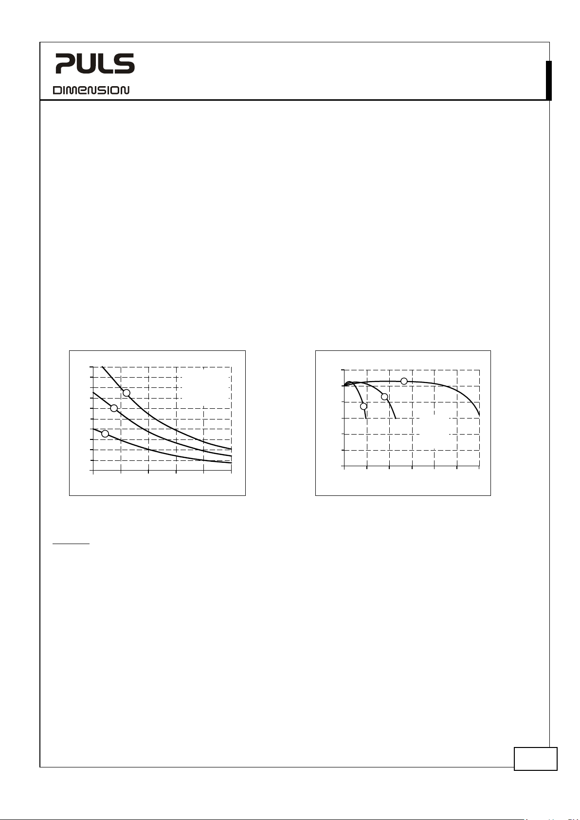
negligible influence in a battery degradation and can be ignored.
27/31
Page 28
UB20.241
UB
MCB
DC-UPS
Output
+
-
+
-
Load
Wire length
S1... Fault simulation switch
S1
0.75mm²
1.0mm²
1.5mm²
2.5mm²
10m
14m
20m
31m
-Series
24V, 20A, DC-UPS
23.2. EXTERNAL INPUT PROTECTION
The DC-UPS is tested and approved for branch circuits up to 28A. An external protection is only required, if the
supplying branch has an ampacity greater than this. If an external fuse is necessary or utilized, minimum requirements
need to be considered to avoid nuisance tripping of the circuit breaker. A minimum value of 25A B- or C-Characteristic
breaker should be used.
Check also local codes and local requirements. In some countries local regulations might apply.
23.3. OUTPUT CIRCUIT BREAKERS
Some applications require branch circuit or branch circuit conductor protection on the 24V supply voltage. Therefore
standard miniature circuit breakers (MCB’s or UL 1077 circuit breakers) are commonly used on 24V branches.
MCB’s are designed to protect wires and circuits. If the ampere value and the characteristics of the MCB are adapted to
the wire size that is used, the wiring is considered as thermally safe regardless of whether the MCB opens or not.
To avoid voltage dips and under-voltage situations in adjacent 24V branches which are supplied by the same source, a
fast (magnetic) tripping of the MCB is desired. A quick shutdown within 10ms is necessary corresponding roughly to
the ride-through time of PLC's. This requires high peak currents to open the circuit breaker in the required time.
Furthermore, the impedance of the faulty branch must be sufficiently small in order for the current to actually flow.
For this discipline, two cases must be differentiated:
A) DC-UPS is operating in power supply mode:
In this case, the supplying source is responsible for the peak current to trip circuit breakers. These values can be
found in the datasheet of the power supply.
B) DC-UPS is operating in battery mode:
The following table has typical test results showing which B- and C-Characteristic MCBs magnetically trip
depending on the wire cross section and wire length (setting for buffer voltage: 22.5V).
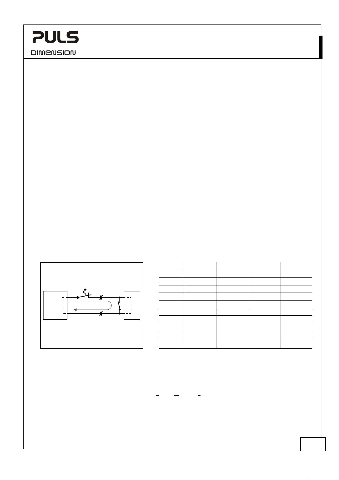
Fig. 23-3 Test circuit
*) Don’t forget to consider twice the distance to the load (or cable length) when calculating the total wire length (+ and – wire).
Maximal wire length
C-2A 25m 34m 48m 72m
C-3A 24m 32m 47m 68m
C-4A 18m 24m 33m 48m
C-6A
C-10A
C-13A
B-6A 23m 26m 32m 46m
B-10A
B-13A
B-16A
*)
for a fast (magnetic) tripping:
10m 12m 18m 28m
5m 6m 9m 13m
1m 2m 2m 3m
9m 10m 18m 27m
3m 4m 9m 13m
23.4. BACK-FEEDING LOADS
Loads such as decelerating motors and inductors can feed voltage back to the DC-UPS. This feature is also called return
voltage immunity or resistance against Back- E.M.F. (Electro Magnetic Force).
This DC-UPS is resistant and does not show malfunctioning when a load feeds back voltage to the power supply. It
does not matter whether the DC-UPS is on or off.
The maximum allowed fed-back-voltage is 35Vdc.
Aug. 2019 / Rev. 2.2 DS-UB20.241-EN
All parameters are specified at 24V, 20A output current, 25°C ambient and after a 5 minutes run-in time unless otherwise noted.
28/31
Page 29
UB20.241
UB
+ +
- -
Power
Supply
DC 24V, 20A
Output
AC Input
L N PE
Load
+
-
YR40.241
+
-
OUT
+
-
IN 1
+
-
IN 2
Ready
Buffering
Inhibit
UB20.241
DC-UPS
IN OUT
+ +
-
-
Inhibit
+ -
Ready
Buffering
BAT
+
-
Replace
Battery
(13)
(12)
(11)
+
-
UZK24
Battery
Module
Center-tap
Temp.
Sensor
UB20.241
DC-UPS
IN OUT
+ +
-
-
Inhibit
+ -
Ready
Buffering
BAT
+
-
Replace
Battery
(13)
(12)
(11)
+
-
UZK24
Battery
Module
Center-tap
Temp.
Sensor
+ +
- -
Power
Supply
DC 24V, 20A
Output
AC Input
L N PE
Buffering
-Series
24V, 20A, DC-UPS
23.5. PARALLEL USE TO INCREASE OUTPUT CURRENT
Two DC-UPSs with two individual power supplies, two battery modules and one decoupling module can be used to
build a system with higher output current.
Fig. 23-4 Wiring example for parallel use to increase the output current
23.6. PARALLEL USE FOR REDUNDANCY
Use the same schematic as for parallel use for higher output current Fig. 23-4 and follow additional the following
recommendations:
a) Use separate input fuses for each power supply.
b) Set the power supply into “Parallel use” mode if available.
c) Use a redundancy module to decouple the two power sources.
d) Monitor the individual sources. Therefore, use the alarm contacts of the power supplies.
e) It is desirable to set the output voltages of all power supplies to the same value (± 100mV) or leave it at the
factory setting.
Aug. 2019 / Rev. 2.2 DS-UB20.241-EN
All parameters are specified at 24V, 20A output current, 25°C ambient and after a 5 minutes run-in time unless otherwise noted.
29/31
Page 30
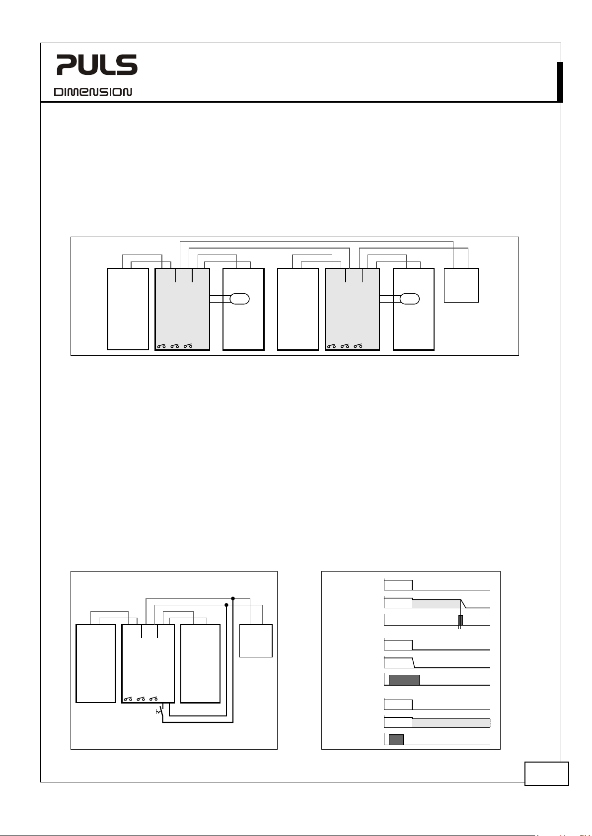
UB20.241
UB
+
+
- -
Power
Supply
DC 24V, 20A
Output
AC Input
L N PE
48V
Load
+
-
UB20.241
DC-UPS
IN OUT
+ +
-
-
Inhibit
+ -
Ready
Buffering
BAT
+
-
Replace
Battery
(13)
(12)
(11)
+
-
UZK24
Battery
Module
Center-tap
Temp.
Sensor
UB20.241
DC-UPS
IN OUT
+ +
-
-
Inhibit
+
-
Ready
Buffering
BAT
+
-
Replace
Battery
(13)
(12)
(11)
+
-
UZK24
Battery
Module
Center-tap
Temp.
Sensor
+
+
- -
Power
Supply
DC 24V, 20A
Output
AC Input
L N PE
+ +
- -
Power
Supply
DC 24V, 20A
Output
AC Input
L N PE
UB20.241
DC-UPS
IN OUT
+ +
-
-
Inhibit
+ -
Ready
Buffering
BAT
+
-
Replace
Battery
+
-
UZK24
Battery
Module
Load
+
-
Input
Output
Inhibit
Input
Output
Inhibit
250ms
Battery Mode
Case
A
Input
Output
Inhibit
Case
B
Battery Mode
Inhibit not activated !
Case
C
-Series
24V, 20A, DC-UPS
23.7. SERIES USE FOR 48V APPLICATIONS
A series connection for 48V applications is allowed when utilizing two individual power supplies, two DC-UPSs and two
battery modules.
Fig. 23-5 Wiring example for 48V serial use
23.8. USING THE INHIBIT-INPUT
The inhibit input is a feature to disable the battery mode on purpose. This can be the case when buffering should
actively be stopped in order to save battery capacity (e.g. when machines are not in use for a long period of time) and
to have shorter recharging times or in case of a service event, where the application must be turned off.
Buffering can be inhibited or stopped:
- When a static voltage is applied to the inhibit input terminals, there will be no buffering after the input voltage is
switched off.
- When, during the battery mode, a short voltage pulse with a minimum length of 250ms is applied to the inhibit
input terminals, the output will switch off and stay off until the input voltage recovers.
Batteries will be charged when the inhibit mode is activated or a voltage is applied to the inhibit input terminals.
Electrical details of the inhibit input are specified in the chapters 9 and 19.
Fig. 23-6 Wiring example for inhibit input Fig. 23-7 Activating the inhibit input
Aug. 2019 / Rev. 2.2 DS-UB20.241-EN
All parameters are specified at 24V, 20A output current, 25°C ambient and after a 5 minutes run-in time unless otherwise noted.
30/31
Page 31
UB20.241
UB
Symptom:
Single flash on the
“
DC
DC
DC
DC
power supply mode
-Series
24V, 20A, DC-UPS
23.9. TROUBLESHOOTING
The following guidelines provide instructions for fixing the most common failures and problems. Always start with the
most likely and easiest to check condition. Some of the suggestions may require special safety precautions. See notes in
section 3 first.
Explanation / Action:
“Error” LED - Check input voltage.
The input voltage must be at least 1V higher than the selected buffer
voltage and smaller than 30V.
Error” LED is solid on - Check correct wiring between the battery and the DC-UPS
- Check battery fuse. Is the battery fuse inserted or blown?
- Check battery voltage (must be between 14.8V and 30V)
- Check battery polarity
-UPS did not buffer - Inhibit input was set.
- Battery did not have enough time to get charged and the battery
voltage is still below the deep-discharge protection level.
-UPS stopped buffering - Deep discharge protection stopped buffering. Use a larger battery, or
allow sufficient time for charging the battery.
- End of service life of the battery
- Battery did not have enough time to be charged.
- Inhibit input was activated
- Buffer time limiter stopped buffering. Change the settings of the buffer
time limiter on the front of the unit.
- At too high temperatures
-UPS stopped buffering for 1s - Center-tap connection opens in buffer mode
- Center-tap connection problems
-UPS constantly switches between
and battery mode
- The supplying source on the input is too small and can not deliver
sufficient current. Use a larger power supply or reduce the output load.
- The output voltage of the power supply dips to a too low value. The
input voltage must always be at least 1V higher than the selected
buffer voltage and smaller than 30V.
Increase the output voltage of the power supply
- Too high voltage drops on wires. Increase the output voltage of the
power supply or increase the wires cross section from the power supply
to the DC-UPS.
Aug. 2019 / Rev. 2.2 DS-UB20.241-EN
All parameters are specified at 24V, 20A output current, 25°C ambient and after a 5 minutes run-in time unless otherwise noted.
31/31
 Loading...