

Page 1

®
LTV
P/N 10664, Rev. T August 2005
Series Ventilator
Operator’s Manual
Page 2

Document Revision History
Document Revision Level Revision Date
Rev A, ECO 390 January 1999
Rev B, ECO 450 February 1999
Rev C, ECO 478 June 1999
Rev D, ECO 685 October 1999
Rev E, ECO 774 March 2000
Rev F, ECO 868 September 2000
Rev G, ECO 956 December 2000
Rev H, ECO 1127 February 2001
Rev J, ECO 1299 May 2001
Rev K, ECO 1496 October 2001
Rev L, ECO 1722 April 2002
Rev M, ECO 1795 June 2002
Rev N, ECO 1978 August 2002
Rev P, ECO 2610 August 2003
Rev. R, ECO 2723 September 2003
Rev. R01, ECO 2735 December 2003
Rev. S, ECO 2907 April 2004
Rev. T ECO 3412 August 2005
Contact Information
Pulmonetic Systems, Inc.
17400 Medina Rd., Suite 100
Minneapolis, Minnesota 55447-1341
Phone: (763) 398-8300
Customer Care Center: (800) 754-1914
Fax: (763) 398-8400
E-mail: [email protected]
Website: http://www.pulmonetic.com
®
1000, LTV® 950, LTV® 900, LTV® 800 and LTV® are trademarks belonging to Pulmonetic
LTV
Systems, Inc.
Copyright © 2005 Pulmonetic Systems, Inc., Minneapolis, Minnesota.
Operator’s Manual LTV® Series ventilator Page i
p/n 10664, Rev. T
Page 3

Warranty
Pulmonetic Systems warrants that the LTV® Series ventilator is free from defects in material and
workmanship for a period of one (1) year from the date of shipment, or 8,800 hours as measured on
the usage meter, whichever comes first, with the following limitations:
1) Patient circuit components, including hoses, exhalation manifold, and other associated parts are
warranted for sixty (60) days from date of shipment.
2) The internal battery is warranted for ninety (90) days from date of shipment.
Pulmonetic Systems will, at its option, either repair, replace, or issue credit for products that prove to
be defective during the warranty period.
For warranty service or repair, the product must be returned to Pulmonetic Systems or a service
facility designated by Pulmonetic Systems, shipping prepaid by the Buyer.
LIMITATION OF WARRANTY
Ordinary maintenance, as specified in the LTV
not covered under the forgoing warranty.
The forgoing warranty does not apply to defects resulting from:
1) Improper or inadequate maintenance of the unit;
2) Improper use or misuse of the unit;
3) Unauthorized modifications or repairs to the unit;
4) Use of the unit with unauthorized accessories, e.g. external battery or AC adapter.
5) Operation of the unit outside the specified environment.
NO IMPLIED WARRANTIES
This warranty is exclusive. There are no other warranties expressed or implied.
LIMITATION OF LIABILITY
Pulmonetic Systems shall not be liable for loss of profits, loss of use, consequential damages, or any
other claim based on breach of warranty. Pulmonetic Systems, Inc.’s liability for damages of any kind
shall be limited to the purchase price of the defective unit.
®
Series ventilator Operator’s and Service Manuals, is
Page ii LTV® Series ventilator Operator’s Manual
p/n 10664, Rev. T
Page 4

Notices
The LTV® Series ventilator complies with limitations as specified in IEC 601-1-2 for Medical Products.
It does however, use and radiate radio frequency energy.
The function of this machine may be adversely affected by the operation of other nearby equipment,
such as high frequency surgical diathermy equipment, short-wave therapy equipment, defibrillators or
MRI equipment.
Federal law restricts this device to sale by or on the order of a physician.
European Regulatory Requirements per 93/42/EEC Medical Device Directives
Pulmonetic Systems, Inc.’s European Representative for vigilance reporting within the European
Community is:
Any product malfunctioning issues that fall under Medical Device Directives Essential Requirements
should be directed to MediMark.
FM 75092
CE 02342
MediMark® Europe Sarl.
11, rue Emile Zola. BP 2332
F-38033 Grenoble Cedex 2. France
Tel: +33 (0)4 76 86 43 22
Fax: +33 (0)4 76 17 19 82
E-mail: [email protected]
Operator’s Manual LTV® Series ventilator Page iii
p/n 10664, Rev. T
Page 5

Notice To Operators
Unsafe Operation - Operating the LTV® Series ventilator without a complete and thorough
understanding of its attributes is unsafe and may cause harm to the patient. It is important that this
manual be read and understood in its entirety before operating the ventilator.
Warnings and Cautions Section - Read the section on Warnings and Cautions carefully before
operating the LTV® Series ventilator.
Use and Maintenance - Any questions regarding installing, operating, or maintaining the LTV®
Series ventilator, should be directed to a certified Pulmonetic Systems’ service technician or
Pulmonetic Systems, Inc.
Avis important
Fonctionnement dangereux - L'opération d'un ventilateur de la série LTV® sans une excellente
compréhension de ses attributs est dangereuse et risque de blesser le patient. Il est très important de
lire et de comprendre entièrement ce manuel avant de faire fonctionner le ventilateur.
Section Avertissements et Attention - Lire attentivement la section Avertissements et Attention
avant de procéder à l'opération des ventilateurs de la série LTV®.
Utilisation et entretien - En cas de questions concernant l'installation, l'opération ou l'entretien des
ventilateurs de la série LTV®, veuillez vous adresser à un technicien de service certifié de Pulmonetic
Systems ou directement à Pulmonetic Systems, Inc.
Page iv LTV® Series ventilator Operator’s Manual
p/n 10664, Rev. T
Page 6

Contents
Warranty ............................................................................................................................................. ii
Notices................................................................................................................................................iii
Chapter 1 - Introduction ...................................................................1-1
Operator’s Safety Information..........................................................................................................1-2
Warnings..........................................................................................................................................1-3
Cautions.........................................................................................................................................1-12
Symbols.........................................................................................................................................1-18
Chapter 2 - Ventilator Overview.......................................................2-1
Intended Use ...................................................................................................................................2-1
Power/Supplies Required................................................................................................................2-2
Information/Assistance ....................................................................................................................2-3
Chapter 3 - Breath Types .................................................................3-1
Breath Types ...................................................................................................................................3-1
Volume Control Breaths...............................................................................................................3-2
Pressure Control Breaths.............................................................................................................3-3
Pressure Support Breaths............................................................................................................3-5
Spontaneous Breaths...................................................................................................................3-6
Chapter 4 - Ventilation Modes..........................................................4-1
Control Mode...................................................................................................................................4-1
Assist/Control Mode.........................................................................................................................4-1
SIMV Mode......................................................................................................................................4-2
CPAP Mode.....................................................................................................................................4-3
Apnea Backup .................................................................................................................................4-4
NPPV...............................................................................................................................................4-5
Volume / Pressure Ventilation .........................................................................................................4-6
Bias Flow .........................................................................................................................................4-6
Chapter 5 - Using the Controls and Indicators ................................5-1
Ventilator Controls...........................................................................................................................5-1
Setting a Control..............................................................................................................................5-2
Variable Controls.............................................................................................................................5-2
Buttons.............................................................................................................................................5-3
Set Value Knob................................................................................................................................5-3
Extended Features ..........................................................................................................................5-3
Mechanical Controls........................................................................................................................5-4
Bright, Dim and Blank Control Displays...........................................................................................5-5
Flashing Controls.............................................................................................................................5-6
Dashes.............................................................................................................................................5-6
Control Limiting................................................................................................................................5-6
Control Locking................................................................................................................................5-7
Operator’s Manual LTV® Series ventilator Page v
p/n 10664, Rev. T
Page 7

Control Retention ............................................................................................................................5-7
Chapter 6 - Controls......................................................................... 6-1
Assist/Control / SIMV/CPAP Modes................................................................................................6-1
Breath Rate.....................................................................................................................................6-2
Control Lock....................................................................................................................................6-3
High Pressure Limit.........................................................................................................................6-4
Inspiratory / Expiratory Hold............................................................................................................6-5
Inspiratory Hold............................................................................................................................6-6
Expiratory Hold ............................................................................................................................ 6-8
Inspiratory Time.............................................................................................................................6-10
Low Minute Volume....................................................................................................................... 6-11
Low Pressure ................................................................................................................................6-12
Low Pressure O2 Source (LTV® 1000 Only) ................................................................................. 6-13
Manual Breath...............................................................................................................................6-17
O2 % (O2 Flush) (LTV® 1000 Only)............................................................................................. 6-18
On / Standby .................................................................................................................................6-20
PEEP Valve...................................................................................................................................6-21
Pressure Control (LTV® 1000 & 950 Only)....................................................................................6-23
Pressure Support ..........................................................................................................................6-25
Select ............................................................................................................................................6-27
Sensitivity......................................................................................................................................6-28
Set Value Knob .............................................................................................................................6-29
Silence / Reset..............................................................................................................................6-30
Tidal Volume .................................................................................................................................6-31
Volume / Pressure Mode (LTV® 1000 & 950 Only)......................................................................6-32
Chapter 7 - Displays and Indicators ................................................ 7-1
Airway Pressure..............................................................................................................................7-1
Display Window............................................................................................................................... 7-1
Indicators.........................................................................................................................................7-1
Battery Level ...................................................................................................................................7-2
Charge Status .................................................................................................................................7-4
External Power................................................................................................................................7-5
NPPV............................................................................................................................................... 7-6
Patient Effort....................................................................................................................................7-6
Vent Inop.........................................................................................................................................7-6
Chapter 8 - Monitored Data.............................................................. 8-1
Automatic or Manual Data Display Scrolling...................................................................................8-2
PIP xxx cmH2O...............................................................................................................................8-3
MAP xx cmH2O...............................................................................................................................8-3
PEEP xx cmH2O.............................................................................................................................8-3
f xxx bpm.........................................................................................................................................8-3
Vte xxx ml........................................................................................................................................8-4
Page vi LTV® Series ventilator Operator’s Manual
p/n 10664, Rev. T
Page 8

VE xx.x L..........................................................................................................................................8-4
I:E xx:xx ...........................................................................................................................................8-4
I:Ecalc xx:xx.....................................................................................................................................8-4
Vcalc xxx Lpm..................................................................................................................................8-4
Chapter 9 - Ventilator Alarms...........................................................9-1
APNEA, APNEA xx bpm..................................................................................................................9-2
BAT EMPTY ....................................................................................................................................9-3
BAT LOW.........................................................................................................................................9-5
DEFAULTS......................................................................................................................................9-7
DEFAULTS SET..............................................................................................................................9-9
DISC/SENSE.................................................................................................................................9-10
HIGH f............................................................................................................................................9-11
HIGH O2 PRES (LTV® 1000 Only)................................................................................................9-12
HIGH PEEP...................................................................................................................................9-13
High PRES.....................................................................................................................................9-14
HW FAULT ....................................................................................................................................9-16
INOP..............................................................................................................................................9-17
LOW MIN VOL...............................................................................................................................9-18
LOW O2 PRES (LTV® 1000 Only).................................................................................................9-19
LOW PRES....................................................................................................................................9-20
NO CAL DATA, NO CAL Monitor Display .....................................................................................9-21
POWER LOST...............................................................................................................................9-22
POWER LOW................................................................................................................................9-23
REMOVE PTNT.............................................................................................................................9-24
RESET...........................................................................................................................................9-25
XDCR FAULT................................................................................................................................9-26
Alarm Status Messages.................................................................................................................9-27
f PEEP OFF................................................................................................................................9-27
HI PEEP OFF.............................................................................................................................9-27
HIGH f OFF................................................................................................................................9-28
LMV LPPS OFF..........................................................................................................................9-28
LMV OFF....................................................................................................................................9-28
LOCKED.....................................................................................................................................9-29
LPPS OFF..................................................................................................................................9-29
WARMUP xx ..............................................................................................................................9-30
Chapter 10 - Extended Features ....................................................10-1
Navigating the Extended Features Menus ....................................................................................10-2
Alarm Operations...........................................................................................................................10-3
Operator’s Manual LTV® Series ventilator Page vii
p/n 10664, Rev. T
Page 9

Alarm Volume ............................................................................................................................ 10-3
Apnea Interval............................................................................................................................ 10-4
High Pressure Alarm Delay ....................................................................................................... 10-4
Low Peak Pressure Alarm.........................................................................................................10-4
High f.......................................................................................................................................... 10-5
High PEEP................................................................................................................................. 10-5
Patient Assist.............................................................................................................................10-6
Exit............................................................................................................................................. 10-6
Vent Operations ............................................................................................................................10-7
Variable Rise Time.....................................................................................................................10-8
Variable Flow Termination......................................................................................................... 10-9
Variable Time Termination....................................................................................................... 10-10
Pressure Control Flow Termination.........................................................................................10-11
Leak Compensation................................................................................................................. 10-12
NPPV Mode.............................................................................................................................10-13
O2 Flush (LTV® 1000 Only).................................................................................................... 10-14
Control Unlock ......................................................................................................................... 10-15
Language Selection................................................................................................................. 10-15
Software Version...................................................................................................................... 10-16
Usage Meter ............................................................................................................................ 10-16
Communications Setting..........................................................................................................10-16
Set Date................................................................................................................................... 10-17
Set Time................................................................................................................................... 10-18
Date Format............................................................................................................................. 10-18
PIP LED...................................................................................................................................10-19
Model Number / Serial Number...............................................................................................10-19
Valve Home Position ............................................................................................................... 10-20
Set Defaults ............................................................................................................................. 10-20
O2 Cylinder Duration (LTV® 1000 Only)................................................................................. 10-21
Exit........................................................................................................................................... 10-22
Transducer Autozero...................................................................................................................10-23
Airway Pressure Transducer Autozero.................................................................................... 10-23
Bi-directional Flow Transducer Differential Autozero .............................................................. 10-24
Exhalation Flow Transducer Differential Autozero - Narrow ...................................................10-25
Exhalation Flow Transducer Differential Autozero - Wide....................................................... 10-26
Real Time Transducers...............................................................................................................10-27
Chapter 11 - Ventilator Checkout Tests........................................ 11-1
Alarm Test.....................................................................................................................................11-3
Display Test...................................................................................................................................11-4
Control Test...................................................................................................................................11-6
Leak Test.......................................................................................................................................11-8
Vent Inop Alarm Test ..................................................................................................................11-10
Exit .............................................................................................................................................. 11-12
Page viii LTV® Series ventilator Operator’s Manual
p/n 10664, Rev. T
Page 10

Chapter 12 - Operating Procedure .................................................12-1
To Turn the Ventilator On..............................................................................................................12-1
Before Connecting the Ventilator to a Patient...............................................................................12-2
Procedure for Control Mode Set Up..............................................................................................12-4
Procedure for Assist / Control Mode Set Up..................................................................................12-5
Procedure for SIMV Mode Set Up.................................................................................................12-6
Procedure for CPAP Mode Set Up................................................................................................12-7
Procedure for NPPV Mode Set Up................................................................................................12-7
Procedure for NPPV Mode Set Up................................................................................................12-8
To Turn the Ventilator Off..............................................................................................................12-9
LTV® Ventilator Settings Checklist..............................................................................................12-10
Chapter 13 - Cleaning, Disinfecting and Sterilizing.......................13-1
Cleaning the Ventilator ..................................................................................................................13-1
Cleaning or replacing the Fan Filter ..............................................................................................13-2
Cleaning or replacing the Inlet Filter..............................................................................................13-3
Cleaning or Replacing the O2 Inlet Filter.......................................................................................13-4
Cleaning the Exhalation Valve and Reusable Patient Circuit........................................................13-6
Chapter 14 - Power and Battery Operation....................................14-1
Using the AC Adapter....................................................................................................................14-2
Using an External Battery..............................................................................................................14-3
Using the Automobile Cigarette Lighter Adapter...........................................................................14-6
Replacing the Automobile Adapter Fuse..................................................................................14-10
The Universal Power Supply (UPS) ............................................................................................14-10
The Transport Battery System (TBS)..........................................................................................14-10
Caring for the Internal Battery .....................................................................................................14-11
Battery Disposal.......................................................................................................................14-11
Chapter 15 - Troubleshooting.........................................................15-1
Displays and Buttons.....................................................................................................................15-2
Ventilator Performance..................................................................................................................15-5
Power and Battery Operation......................................................................................................15-14
Alarms..........................................................................................................................................15-16
Checkout Test Failures................................................................................................................15-21
Test Lung Operations..................................................................................................................15-23
Appendix A - Ventilator Specifications............................................ A-1
Appendix B - Set Up / Maintenance..................................................B-1
Recommended Maintenance Schedule.......................................................................................... B-1
Service Assistance ......................................................................................................................... B-2
Appendix C - Installation and Checkout ..........................................C-1
Installation and Setup..................................................................................................................... C-1
Operator’s Manual LTV® Series ventilator Page ix
p/n 10664, Rev. T
Page 11

Unpacking the Ventilator – Instructions.......................................................................................C-1
Protective Boots...........................................................................................................................C-2
Protective Boot Removal.............................................................................................................C-3
Protective Boot Installation..........................................................................................................C-6
Patient Breathing Circuit – Connection Instructions....................................................................C-9
Patient Breathing Circuit – Connection Instructions..................................................................C-10
Oxygen Lines – Connection Instructions...................................................................................C-12
Patient Assist Call System – Connection Instructions...............................................................C-14
Communications Port ................................................................................................................C-15
LTM™ Graphics Monitor............................................................................................................C-15
Using the Remote Alarm Cable.................................................................................................C-16
Checking the Ventilator for Proper Operation............................................................................C-18
Ventilator Proper Operation Worksheet.....................................................................................C-20
Appendix D - Principles of Operation...............................................D-1
Overview .........................................................................................................................................D-1
Appendix E - Event Trace ................................................................ E-1
Event Codes....................................................................................................................................E-3
Event Codes by Code #...............................................................................................................E-3
Event Codes by Event Name.......................................................................................................E-6
Appendix F - Glossary...................................................................... F-1
Appendix G - Index...........................................................................G-1
Page x LTV® Series ventilator Operator’s Manual
p/n 10664, Rev. T
Page 12

Chapter 1 -
This Operator’s Manual contains detailed information and instructions which when adhered to, ensure
the safe and effective set up, use and simple maintenance of the LTV
Ventilators.
It is designed for use by Respiratory Therapists or other qualified and trained personnel under the
direction of a physician and in accordance with applicable state laws and regulations. It contains the
following:
• Ventilator Overview
• Installation and Checkout
• Using the Controls and Indicators
• Monitored Data
• Ventilator Alarms
• Extended Features
• Ventilator Checkout tests
• Operating Procedure
• Troubleshooting
• Cleaning, Disinfecting and Sterilizing
• Set Up / Maintenance
• Power and Battery Operation
Service tests, calibration, and major maintenance operations are described in the LTV
ventilator Service Manual (P/N 10665).
I
NTRODUCTION
®
1000, 950, and 900
®
Series
Operator’s Manual LTV® Series ventilator Page 1-1
p/n 10664, Rev. T
Page 13

Operator’s Safety Information
All Operators are to read and understand the following information about Warning, Caution and
Note statements before operating the LTV
WARNING
“WARNING” statements alert the reader to potentially hazardous situations which, if not avoided,
could result in death or serious injury.
AVERTISSEMENT
Les énoncés « AVERTISSEMENT » informent le lecteur de situations dangereuses qui, si elles ne
sont pas évitées, peuvent entraîner la mort ou des blessures graves.
®
Series ventilator.
CAUTION
“CAUTION” statements alert the reader to potentially hazardous situations which, if not avoided,
could result in equipment damage.
ATTENTION
Les énoncés « ATTENTION » informent le lecteur de situations dangereuses qui, si elles ne sont pas
évitées, peuvent causer des dommages à l’équipement.
NOTE
“NOTE” statements contain additional information to assist in the proper operation of the LTV® Series
ventilator.
REMARQUE
Les énoncés « REMARQUE » contiennent des informations sup plémentaires pour aider à l'opération
adéquate des ventilateurs de la série LTV®.
Page 1-2 LTV® Series ventilator Operator’s Manual
p/n 10664, Rev. T
Page 14

Warnings
WARNING
Untrained Personnel – Only properly trained personnel should operate the ventilator. The LTV®
Series ventilator is a restricted medical device designed for use by Respiratory Therapists or o t her
properly trained and qualified personnel under the direction of a physician and in accordan ce with
applicable state laws and regulations.
Leak Testing the Patient Breathing Circuit – The patient circuit must be leak tested in the VENT
CHECK mode before connection to the patient. In addition, the Ventilator Checkout mode should be
used to check for correct operation of the ventilator alarm, displays and controls. Harm to the patient
or ineffective ventilation may result from failure to leak test the patient breathing circuit before
connection to a patient. When using a heated humidifier, include it in the circuit when performing leak
testing.
Adjustable and Critical Alarms – For safety purposes, all adjustable alarms and all critical alarms
must be checked to insure proper operation.
Alarms Function Verification - All alarms must be verified as functioning properly on a daily basis. If
any alarm malfunctions, immediately contact a certified Pulmonetic Systems’ service technician or
Pulmonetic Systems, Inc.
Patient Monitoring - Patients who are dependent on a ventilator should be constantly monitored by
qualified personnel. Such personnel should be prepared to address equipment malfunctions and
circumstances where equipment becomes inoperative. An alternative method of ventilation should be
available for all patients dependent on the ventilator, and qualified personnel should be fully familiar
with emergency ventilation procedures.
Alternative Ventilation - It is recommended that an alternative means of ventilating the patient be
available at all times and that all ventilator operators be fully familiar with emergency ventilation
procedures.
Fire or Explosion - Operation of the LTV® Series ventilator in the presence of flammable gases
could cause a fire or explosion. Under no circumstances is the ventilator to be operated when
explosive gases are present. The presence of nitrous oxide or flammable anesthetics presents a
danger to the patient and operator.
Patient Breathing Circuit Disconnection - Inadvertent disconnection of the patient from the patient
breathing circuit can be dangerous.
Critical Alarms - Failure to set the critical alarms such as the Low Minute Volume alarm and the Low
Pressure alarm may cause non-detection (no alarm) for a disconnection of the lower sense line or the
exhalation valve drive line.
Exhalation Valve Diaphragm – Patient ventilation may be ineffective or dangerous if the exhalation
valve diaphragm is damaged or worn out. The exhalation valve diaphragm must be inspected on a
daily basis and replaced whenever necessary.
Sustained HIGH PRES Alarm - During a sustained High Pressure alarm condition (HIGH PRES), the
ventilator’s turbine is stopped and gas is not delivered to the patient. Disconnect the patient from the
ventilator and ventilate the patient using an alternative method. See Chapter 15 - Troubleshooting,
Alarms for additional information concerning the HIGH PRES alarm.
Operator’s Manual LTV® Series ventilator Page 1-3
p/n 10664, Rev. T
Page 15

WARNING
BAT EMPTY Alarm - A BAT EMPTY alarm indicates the internal battery is almost depleted. Connect
the ventilator to an external power source immediately.
Battery run time - When the battery reaches the BAT LOW level, the ventilator will only run for
approximately 10 minutes before generating a battery empty alarm (BAT EMPTY). The approximate
time shown is based on tests using the nominal settings, a new battery and a full 8 hour charge cycle
as specified in Appendix A - Ventilator Specifications. Actual run time may be more or less depending
on ventilator settings, patient demand, and battery age or condition. It is highly recommended that an
alternate power source is connected PRIOR to the ventilator reaching the BAT EMPTY alarm
condition to ensure continuous, uninterrupted patient ventilation
INOP Alarm - If an INOP alarm occurs during operation, ventilate the patient using an alternative
method, disconnect the ventilator, and immediately contact a certified Pulmonetic Systems’ service
technician or Pulmonetic Systems, Inc.
NO CAL Condition - Operation of the LTV® Series ventilator under a NO CAL condition may result
in inaccurate pressure and volume measurements. Should this condition occur, disconnect the patient
from the ventilator, provide an alternative method of ventilation and immediately contact a certified
Pulmonetic Systems’ service technician or Pulmonetic Systems, Inc.
XDCR FAULT Alarm - Continued operation of the LTV® Series ventilator with an activated XDCR
FAULT alarm may result in inaccurate flow and volume measurements. Should this condition occur,
disconnect the patient from the ventilator, provide an alternative method of ventilation and
immediately contact a certified Pulmonetic Systems’ service technician or Pulmonetic Systems, Inc.
Personal Injury and Electric Shock - Operation of the LTV® Series ventilator if any of its panels
have been removed may result in electrical shock to the patient or operator. All servicing must be
performed by a certified Pulmonetic Systems’ service technician.
NPPV Mode – NPPV1 is not a life support mode and is not suitable for patients that require life
support ventilation. NPPV Mode should only be used for supplemental ventilation of non-life support
patients.
NPPV Mode - When operating in NPPV1 mode, many of the standard alarms are disabled. This may
result in reduced ventilation accuracy should a problem occur. Carefully read Chapter 4 - Ventilation
Modes,
NPPV, before selecting this mode of operation.
Accuracy of PEEP setting - Variations in the patient’s breathing pattern and/or leaks in the patient
circuit (including leaks around the tracheostomy tube cuff) can affect PEEP. PSI recommends that the
clinician set the PEEP to the prescribed level on a test lung while observing the PEEP value in the
LTV display window. The clinician should also periodically monitor the PEEP value in the LTV display
window. Using an inaccurate PEEP setting due to a patient leak can result in less than prescribed
PEEP or undesirable increases in patient circuit pressure when the patient circuit leak changes.
Audible Alarms - Failure to immediately identify and correct audible alarm situations may result in
serious patient injury.
1
NPPV, Non-Invasive Positive Pressure Ventilation
Page 1-4 LTV® Series ventilator Operator’s Manual
p/n 10664, Rev. T
Page 16

WARNING
Equipment Malfunction or Failure - The LTV® Series ventilator has alarms to notify operators of
certain conditions and to cease operating upon detecting possible danger. In the event of equipment
failure, all ventilator operators should have an alternative method of ventilation available and be fully
familiar with emergency ventilation procedures.
Improperly Functioning Ventilator - Operation of a ventilator that does not appear to be working
properly may be hazardous. If the ventilator is damaged, fails Ventilator Checkout tests or
malfunctions in any way, discontinue its use and immediately contact a certified Pulmonetic Systems’
service technician or Pulmonetic Systems, Inc.
Ventilator Checkout Tests – Be aware that gas is not delivered to the patient during these tests.
Disconnect the patient from the ventilator and ventilate the patient using an alternative method before
running the Ventilator Checkout tests.
Ventilator Checkout and Maintenance Modes - The LTV® Series ventilator does not deliver gas
during the Ventilator Checkout mode (VENT CHECK) or Ventilator Maintenance mode (VENT
MTNCE) and should not be used to ventilate a patient during these tests.
Inspired Oxygen (FIO2) Concentration – If the patient has a variable respiratory rate, his/her
minute ventilation will fluctuate. If exact concentrations of inspired oxygen (FIO2) are required to be
delivered to the patient, it is recommended that an accurate oxygen analyzer with alarms be used.
O2 Cylinder Duration Information - The accuracy of the displayed useable amount of oxygen
remaining in an external O2 cylinder (O2 DUR hh:mm) is dependant on the precision of the pressure
gauge used on the O2 cylinder and the accuracy of the information provided by the operator in the O2
CYL DUR menu settings. The calculated/displayed useable amount of oxygen information is to be
used for reference purposes only.
Ventilation Variables and O2 Consumption - Variations in the patient’s minute ventilation, I:E ratio
and/or ventilator setting changes or equipment status (i.e. circuit leaks) affect the consumption rate of
oxygen. When warranted by a patients condition, it is recommended that a back-up cylinder or
alternative source of oxygen be available at all times.
Before Using Automobile Cigarette Lighter or Power Outlets - Before using Automobile Cigarette
Lighter or Power Outlets as a power source for the LTV® ventilator, assure that the ventilator’s
internal battery is in good condition and fully charged. Poor cigarette lighter or power outlet
connections, electrical system defects (battery, charging system, etc.), or use of vehicle accessori es
(air conditioner, high current lights, high power audio equipment, etc.) could result in less than the
required voltage being delivered to the ventilator, generate a Power Lost alarm and switch the
ventilator’s power source to the internal battery.
Unauthorized Parts or Accessories – Serious harm to the patient may result from the use of
unauthorized parts or accessories. Only items expressly approved by Pulmonetic Systems may be
used in conjunction with the LTV® Series ventilators.
Unapproved Adapters – Only Pulmonetic Systems Accessories should be used to connect the
ventilator to Patient Assist Call Systems. These accessories incorporate safety features to reduce the
risk of shock. Do not attempt to modify these accessories in any way.
Patient Assist Call Connector – Do not apply more than 25V rms or 32VDC to the Patient Assist
Call connector.
Operator’s Manual LTV® Series ventilator Page 1-5
p/n 10664, Rev. T
Page 17

WARNING
Ventilator Service and Repair - All servicing or repair of the LTV® Series ventilator must be
performed only by a service technician certified by Pulmonetic Systems
Disabled Oxygen Inlet Pressure Alarms - When the oxygen blending option is not installed, the
Oxygen Inlet Pressure Alarms are disabled.
Patient Circuits – Pulmonetic Systems Patient Circuits, Exhalation Valve Assemblies and Water
Traps are shipped clean, not sterile.
Ultra Violet Light Sensitivity – The material used in the tubing of the “Re-usable” Patient Circuits is
not UV stable. Avoid exposure of the tubing to UV light.
PEEP Valve Rotation – Attempting to adjust the PEEP valve counterclockwise past zero (0) may
damage the PEEP valve assembly or cause circuit leaks.Accessories
Mounting Screws - Refer to the information contained in Pulmonetic Systems Replacement Screws
Kit, P/N 11149, to determine the appropriate accessories mounting screws or accessories
replacement screws location, type and length to use when removing or exchanging external
accessories on an LTV® Series ventilator.
Mounting Screw Use – Internal damage to the ventilator may result if the wrong length mounting
screws are used when installing or removing external accessories.
Specific Boot Replacement Screw Location - One leg of the upper protective boot has an
additional screw hole (furthest from the end of the leg); On earlier version ventilators (screw was
located in the upper hole in the leg of the boot) the use of a 3/16” mounting screw is required. On
current version ventilators (screw was located in the lower hole in the leg of the boot) the use of a 1/4”
mounting screw is required.
Specific Boot Installation Screw Location - One leg of the upper protective boot has an additional
screw hole (furthest from the end of the leg);On earlier version ventilators, the screw hole will align
with the upper hole in the boot and requires the use of the 1/4” mounting screw. On current version
ventilators, the screw hole will align with the lower hole in the boot and requires the use of the 3/8”
mounting screw.
Patient Circuit Accessories - The use of accessories such as Spea king Valves, Heat-Moisture
Exchangers and Filters create additional patient circuit resistance and in the event of a disconnectio n,
may impede the generation of a Low Pressure Alarm. Ensure that the Low Pressure Alarm settings
accommodate these types of accessories when used in combination with patient circuits.
Low Minute Volume Control Settings - The Low Minute Volume control should be set to its highest
clinically appropriate value. If there is a clinical need to set the Low Minute Volume alarm to lower
values or off (“- - -“), perform a clinical assessment to determine if an alternative monitor (i.e. a Pulse
Oxymeter with an audible alarm, or a Cardio Respiratory Monitor) should be used.
Page 1-6 LTV® Series ventilator Operator’s Manual
p/n 10664, Rev. T
Page 18

AVERTISSEMENT
Personnel non qualifié - Seul le personnel qualifié doit opérer le ventilateur. Le ventilateur de la
série LTV® est un dispositif médical restreint conçu pour être utilisé par les inhalothérapeutes ou
autres personnes qualifiées, et par le personnel qualifié sous la supervision d'un médecin et en
conformité avec les lois et règlements applicables.
Contrôle de l’étanchéité du circuit respiratoire du patient – L'étanchéité du circuit respiratoire du
patient (vérification de ventilation) doit être vérifiée en mode VENT CHECK avant le raccordement au
patient. En outre, on doit utiliser le mode Ventilator Checkout (vérification du ventilateur) afin de
s’assurer du fonctionnement adéquat de l’alarme, des affichages et des comma ndes du ventilateur.
Le défaut de vérifier l’étanchéité du circuit respiratoire du patient avant le raccordement à un patient
peut être nocif pour le patient ou provoquer une ventilation inefficace. Lorsqu’un humidificateur
chauffant est employé, il convient de l’inclure dans le circuit en procédant à la vérification de
l’étanchéité.
Alarmes ajustables et critiques - Afin d'assurer l'opération sécuritaire des ventilateurs de la série
LTV®, toutes les alarmes ajustables doivent être réglées avant l'opération. De plus, toutes les
alarmes critiques (par exemple, alarme de basse pression), doivent être inspectées avant de laisser
le patient seul.
Vérification du fonctionnement des alarmes - Toutes les alarmes sonores et visuelles doivent être
vérifiées quotidiennement. Si une des alarmes fonctionne de façon inadéquate, contactez votre
technicien de service certifié de Pulmonetic Systems ou Pulmonetic Systems Inc.
Surveillance du patient – Un personnel qualifié doit constamment surveiller les patients qui sont
reliés à un ventilateur. Le personnel doit être en mesure de s’occuper des défectuosités de
fonctionnement de l’équipement ainsi que des circonstances où ce dernier devient inopérant. Une
forme de ventilation alternative doit être disponible à tous les patients reliés au ventilateur et le
personnel qualifié devrait être pleinement familier avec les procédures de ventilation d’urgence.
Ventilation alternative - Il est recommandé qu'un moyen alternatif de ventilation soit disponible en
tout temps, et que tous les opérateurs de ventilateur soient pleinement familiers avec les procédures
de ventilation d'urgence.
Feu ou explosion - L'opération des ventilateurs de la série LTV® en présence de gaz inflammables
peut causer un feu ou une explosion. Le ventilateur ne doit être opéré sous aucune circonstance en
présence de gaz. La présence d'oxyde nitreux ou d'anesthésiques inflammabl es représente un
danger pour le patient et l'opérateur.
Débranchement du circuit respiratoire du patient - Le débranchement acciden t el du circuit
respiratoire du patient peut s'avérer dangereux.
Alarmes critiques – Le défaut de définir les alarmes critiques telles que l’alarme basse ventilationminute et l’alarme basse pression peut causer une non-détection (absence d’alarme) pour un
débranchement du tube de détection inférieur ou du tube d’entraînement de la soupape d’expiration.
Diaphragme de la soupape d'expiration - Une ventilation inefficace ou dangereuse pour le patient
peut résulter si le diaphragme de la soupape est endommagé ou usé. Le diaphragme de la soupa pe
d'expiration doit être vérifié quotidiennement, et remplacé au besoin.
Alarme ALARME PMAX continue — Dans des conditions d’alarme de haute pression prol ongées
(ALARME PMAX), la turbine du ventilateur s'arrête et le gaz n’est plus transmis au patient.
Débranchez le patient du ventilateur et utilisez une autre méthode de ventilation. Pour plus de détails
sur l’état ALARME PMAX, reportez-vous au chapitre 15, Troubleshooting, Alarms.
Operator’s Manual LTV® Series ventilator Page 1-7
p/n 10664, Rev. T
Page 19

AVERTISSEMENT
Durée d’utilisation de la batterie – Lorsque la batterie atteint le niveau BAT INT BASS, le
ventilateur fonctionne pendant environ 10 minutes avant d’émettre une alarme de batterie faible (BAT
INT VIDE). Cette durée approximative est basée sur des tests avec des paramètres nominaux, une
nouvelle batterie et un cycle de chargement complet de 8 heures, tel que spécifié dans l’Annexe A –
Spécifications du ventilateur. La durée d’utilisation réelle pourrait être supérieure ou inférieure, selon
les paramètres du ventilateur, la demande du patient et l’âge ou l’état de la batterie. Il est fortement
recommandé qu’une source d’alimentation alternative soit connectée AVANT que le ventilateur
n’atteigne l’état d’alarme BAT INT VIDE afin d’assurer une ventilation continue et ininterrompue au
patient.
Alarme BAT EMPTY - Une alarme BAT EMPTY indique que la pile interne est pratiquement à plat.
Branchez immédiatement le ventilateur à une source d'alimentation externe.
Alarme INOP - Si une alarme INOP survient au cours de l'opération, ventilez le patient à l'aide de la
méthode alternative, retirez immédiatement le ventilateur du service, et contactez immédiatement
votre technicien de service certifié de Pulmonetic Systems ou Pulmonetic Systems Inc.
Condition NO CAL - L'opération continue du ventilateur de la série LTV® sous condition NO CAL
peut résulter en mesures de pression et de volume erronées. Si cette condition se présente, le
ventilateur doit être retiré du service, et vous devez immédiatement contacter votre technicien de
service certifié de Pulmonetic Systems ou Pulmonetic Systems Inc.
Alarme XDCR FAULT - L'opération continue du ventilateur de la série LTV® avec une alarme XDCR
FAULT activée peut résulter en mesures de débit et de volume erronées. Si cette condition se
présente, le ventilateur doit être retiré du service, et vous devez immédiatement contacter votre
technicien de service certifié de Pulmonetic Systems ou Pulmonetic Systems Inc.
Blessures personnelles et chocs électriques - L'opération d’un ventilateur de la série LTV® alors
que ses panneaux sont enlevés, peut causer un choc électrique au patient ou à l'opérateur. Tout
entretien doit être effectué par un technicien de service certifié de Pulmonetic Systems.
Mode NPPV – Le mode NPPV n’est pas un mode de maintien des fonctions vitales continu et il n’est
pas approprié pour les patients qui ont besoin d’une ventilation continue pour le maintien des
fonctions vitales. Le mode NPPV ne doit être utilisé que comme ventilation supplémentaire pour les
patients qui ne nécessitent pas de maintien des fonctions vitales.
Mode NPPV – Lorsque l’appareil fonctionne en mode NPPV, bon nombre des alarmes standards
sont désactivées. Par conséquent, si un problème survient, la précision de la ventilation pourrait
diminuer. Assurez-vous de lire attentivement le chapitre 4 – Types de respiration et modes de
ventilation, mode NPPV avant de choisir ce mode de fonctionnement.
Exactitude du paramètre PEP – Les écarts dans le mode de respiration du patient et/ou les fuites
du circuit du patient (y compris les fuites autour du ballonnet pour canule de trachéostomie) peuvent
affecter le PEP. Des études et investigations préliminaires recommandent que le clinicien définisse le
PEP au niveau prescrit sur un poumon d’essai tout en observant la valeur PEP de l’écran graphique
LTV. Le clinicien doit par ailleurs surveiller de façon périodique la valeur PEP de l’écran graphique
LTV. L’utilisation d’un paramètre PEP inapproprié en raison d’une fuite de patient peut
potentiellement résulter en un paramètre inférieur au paramètre PEP prescrit ou en une
augmentation indésirable de la pression du circuit du patient lorsque la fuite du circuit du patient
change.
Alarmes sonores - L'échec à identifier et à corriger dans l'immédiat les situations d'alarm es sonores
peut causer des blessures au patient.
Page 1-8 LTV® Series ventilator Operator’s Manual
p/n 10664, Rev. T
Page 20

AVERTISSEMENT
Mauvais fonctionnement ou panne de l'équipement - Des dispositifs électromécaniques peuvent
mal fonctionner ou subir une panne. Le ventilateur de la série LTV® a été conçu avec des alarmes,
pour détecter et aviser les opérateurs de certaines conditions, et pour cesser d'opérer en cas de
conditions d'opération dangereuses. En cas de panne de l'équipement, tous les opérateurs du
ventilateur devraient avoir une forme de ventilation alternative à leur disponibilité, et être pleinement
familiers avec les procédures de ventilation d'urgence.
Ventilateurs fonctionnant de façon inadéquate - L'opération d'un ventilateur dont le
fonctionnement semble inadéquat peut représenter un danger. Si le ventilateur est endommagé, s'il
échoue les tests de vérification du ventilateur ou s'il fonctionne de façon inadéquate, suspendez
l'utilisation de ce ventilateur et contactez immédiatement votre technicien de service certifié de
Pulmonetic Systems Inc.
Tests de vérification du ventilateur – Noter que le gaz n’est pas transmis au patient au cours de
ces tests. Débrancher le patient du ventilateur et ventiler le patient à l’aide d’une forme de ventilation
alternative avant de procéder aux tests de vérification du ventilateur.
Modes Vérification et Entretien du ventilateur - Le ventilateur de la série LTV® ne transmet pas le
mélange de gaz en mode Vérification du ventilateur (VENT CHECK) ou en mode Entretien du
ventilateur (VENT MTNCE), il ne devrait donc pas être utilisé pour ventiler un patient durant
l'exécution de ces tests.
Concentration d’oxygène inspiré (FIO2) – Si la fréquence respiratoire du patient est variable, sa
ventilation-minute va fluctuer. Lorsqu’une concentration exacte d’oxygène inspiré (FIO2) est
nécessaire pour une transmission au patient, il est recommandé d’utiliser un analyse ur de niveau
d’oxygène2 précis, comportant des alarmes.
Informations sur la durée d'utilisation restante de la bouteille d’oxygène - La précision de
l’affichage de la quantité d’oxygène utilisable restante dans une bouteille d’oxygène externe (O2 DUR
hh:mm) dépend de la précision de la jauge de pression utilisée sur la bouteille et de l'exactitude des
informations fournies par l’opérateur dans les paramètres du menu DUREE CYL O2. Les
informations calculées et affichées sur la quantité d’oxygène utilisable ne doivent être utilisée s qu’à
titre indicatif.
Variables de ventilation et consommation d’oxygène — Les variations dans la ventilation par
minute du patient et dans le rapport inspiration/expiration, la modification des paramètres ou l’état du
matériel (fuite dans le circuit, par exemple) modifient le taux de consommation de l’oxygène. Lorsque
la situation du patient le permet, il est recommandé qu'une bouteille d’oxygène de secours ou toute
autre source alternative d’oxygène soit disponible en permanence.
Avant toute utilisation d’une prise d’allume-cigare ou d’une prise de courant — Avant d’utiliser
un allume-cigare ou une prise de courant comme source d’alimentation du ventilateur LTV®, vérifiez
que la batterie interne du ventilateur est en bon état et entièrement chargée. L’utilisation d’un allumecigare ou d’une prise de courant fournissant un branchement de qualité médiocre, des défauts du
circuit électrique (batterie, système de charge, etc.), ou l’utilisation d’accessoires d’automobile
(climatisation, phares, chaîne stéréo et haut-parleurs à forte consommation, etc.) peuvent affecter le
voltage délivré au ventilateur et provoquer une sous-alimentation de celui-ci. Dans cette situation, le
ventilateur déclenche une alarme PAS ALIM SEC et utilise la batterie interne du ventilateur comme
source d’alimentation.
Pièces, accessoires et options non autorisées - Des dommages à l'équipement ou des blessures
au patient peuvent survenir suite à l'utilisation de pièces, accessoires et options non autorisées.
Seuls les éléments expressément approuvés par Pulmonetic Systems doivent être utilisés en
conjonction avec les ventilateurs de la série LTV®.
Operator’s Manual LTV® Series ventilator Page 1-9
p/n 10664, Rev. T
Page 21

AVERTISSEMENT
Accessoires non approuvés – L’utilisation d’accessoires qui ne sont pas expressément approuvés
par Pulmonetic Systems pourrait entraîner des conditions dangereuses. Seuls les accessoires de
Pulmonetic Systems devraient être utilisés pour brancher les ventilateurs aux systèmes d’aide aux
patients. Ces accessoires comportent des caractéristiques de sécurité pour réduire les risques de
choc. N’essayez pas de modifier ces accessoires d’aucu ne façon.
Connecteur d’appel d’aide aux patients – Ne mettez pas plus de 25 V efficace ou 32 V c.c. au
connecteur d’appel d’aide aux patients.
Entretien et réparation du ventilateur - Tout entretien ou réparat ion du ventilateur de la série LTV®
ne doit être effectué que par un technicien de service certifié de Pulmonetic Systems.
Alarmes de pression d'entrée de l'oxygène désactivées - Lorsque l'option de mélange d'oxygène
n'est pas activée, les alarmes de pression d'entrée de l'oxygène sont désactivées.
Circuits du patient – Les circuits du patient du Pulmonetic Systems, les valves expiratoires et les
collecteurs d’eau sont expédiés propres, mais pas stériles.
Sensibilité à la lumière ultraviolette – Les matériaux utilisés pour la tubulure des circuits du patient
ne sont pas stables sous rayons UV. Éviter d’exposer la tubulure à la lumière UV.
Rotation de la valve de pression expiratoire positive – Si vous essayez d’ajuster la valve de
pression expiratoire positive en sens inverse des aiguilles d’une montre passé zéro (0), vous pourriez
endommager la valve de pression expiratoire positive ou causer une fuite dans le circuit.
Vis de montage des accessoires – Voir les renseignements fournis dans la trousse de vis de
remplacement de Pulmonetic Systems, numéro de pièce 11149, pour déterminer l’emplacement, le
type et la longueur des vis de montage d’accessoires ou des vis de remplacement pour accessoires à
utiliser lors de la dépose ou de l’échange d’accessoires externes sur un ventilateur de la série LTV®.
Utilisation des vis de montage – Vous pourriez causer des dommages internes au ventilateur si
des vis de montage de mauvaise longueur sont utilisées lors de l’installation ou de la dépose des
accessoires externes.
Emplacement des vis de remplacement d’un gaine spécifique – Une patte de la gaine protectrice
supérieure possède un trou de vis supplémentaire (le plus éloigné de l’extrémité de la patte);
• Sur les anciennes versions des ventilateurs (la vis se trouvait dans le trou supérieur de la patte
de la gaine), vous devez utiliser une vis de montage de 3/16”.
• Sur la version actuelle des ventilateurs (la vis se trouve dans le trou inférieur de la patte de la
gaine), vous devez utiliser une vis de montage de 1/4”.
Emplacement des vis d’installation d’un gaine spécifique – Une patte de la gaine protectrice
supérieure possède un trou de vis supplémentaire (le plus éloigné de l’extrémité de la patte);
• Sur les anciennes versions des ventilateurs, le trou de la vis s’alignera au trou supérieur de la
gaine et vous devez utiliser une vis de montage de 1/4".
• Sur la version actuelle des ventilateurs, le trou de la vis s’alignera au trou inférieur de la gaine et
vous devez utiliser une vis de montage de 3/8”.
Page 1-10 LTV® Series ventilator Operator’s Manual
p/n 10664, Rev. T
Page 22

AVERTISSEMENT
Accessoires du circuit du patient - L’utilisation d’accessoires tels que les membranes vocales, les
échangeurs thermohydriques et les filtres, produit une résistance a dditionnelle dans le circuit de
patient et en cas de débranchement, elle risque d’empêcher la génération de l’al arme de basse
pression. S’assurer que les paramètres de l’alarme de basse pression s’adaptent à ces types
d’accessoires lorsqu’ils sont utilisés avec les circuits du patient.
Réglages du contrôle de volume bas par minute - Le contrôle du volume bas par minute doit être
ajusté à la plus haute valeur clinique appropriée. Si l’alarme de volume bas par minute doit être
ajustée à des valeurs inférieures ou mise à l’arrêt (“- - -“) p our satisfaire aux besoins cliniques,
effectuer une évaluation clinique afin de déterminer si l’utilisation d’un autre moniteur (c.-à-d.,
sphygmo-oxymètre muni d’une alarme sonore ou un moniteur cardio-respiratoire) s’avère pertinente.
Operator’s Manual LTV® Series ventilator Page 1-11
p/n 10664, Rev. T
Page 23

Cautions
CAUTION
Ventilator Sterilization – To avoid irreparable damage to the LTV® Series ventilator, do not attempt
to sterilize it.
Cleaning Agents – To avoid damaging the ventilator’s plastic components and front panel, do not
use cleaning agents containing ammonium chloride, other chloride compounds, more than 2%
glutaraldehyde, phenols, or abrasive cleaners.
Ventilator Immersion - Do not immerse the ventilator in liquids.
Reusable Patient Circuit Components - To avoid degradation of the reusable patient circuit
components, do not exceed the following constraints:
• 50 cleaning cycles or 1 year (whichever comes first)
Steam Autoclave:
• Pressure: 20 PSIG
• Temperature: 275°F (135°C)
• Time: 6 minutes
Liquid Sterilizing Agent:
• The use of liquid agents containing more than 2% glutaraldehyde.
Pasteurization:
• A 30-minute warm water detergent and a 30-minute 165°F (74°C) hot water cycle.
• Drying in a sterile drier for more than 1 hour or 140°F (59°C).
Gas (ETO):
• Temperature: 131°F (55°C)
Differential Pressure Ports - A low pressure air nozzle with flow less than 10 liters per minute
should be used for cleaning the differential pressure ports.
Exhalation Valve Cleaning - Do not pour or spray liquid cleaners into the exhalation valve.
Patient Wye Installation – After cleaning, install the patient wye in the patient circuit so the proximal
sense lines are oriented up while operating.
Care of the Exhalation Valve - The exhalation valve is a delicate assembly and may be damaged if;
• Care is not exercised when handling or cleaning it.
• Cleaning instruments or foreign bodies are inserted into it.
• High-pressure gas nozzles are used to dry it.
Front Panel Cleaning – Do not pour or spray liquid cleaners onto the front panel.
Care of Bacterial Filters – If bacterial filters are used in conjunction with the LTV® Series ventilator,
comply with all procedures as specified by the filter manufacturer.
Wet or Damp Filters - Do not install a wet or damp filter into the LTV® Series ventilators. This could
damage the ventilator.
Page 1-12 LTV® Series ventilator Operator’s Manual
p/n 10664, Rev. T
Page 24

CAUTION
Oxygen Supply Contamination - The accuracy of the oxygen delivery capabilities of LTV®
ventilators can be compromised by foreign debris contamination in the oxygen supply system. To
reduce the risk of airborne contaminants entering the ventilator, ensure that any oxygen supply
connected to the ventilator is clean, properly filtered2 and that the ventilator’s O2 Inlet Port Cap is
securely installed on the O2 Inlet Port whenever the ventilator is not connected to an external oxygen
supply.
Proximal Sense Lines - Do not remove the proximal sense lines from the patient wye.
Automobile Cigarette Lighter and Power Outlets – Automobile cigarette lighter and power outlets
are normally wired for a positive center contact and ground sleeve contact. Connecting the ventilator
to an improperly wired outlet will cause the adapter fuse to blow and may damage the adapter or the
ventilator.
Automobile Cigarette Lighter Outlet Power Rating - Running a ventilator from an improperly rated
automobile cigarette lighter outlet (less than 20 amperes) may cause a fuse in the automobile to blow,
causing the ventilator and possibly other accessories in the automobile to stop operating.
Automobile Cigarette Lighter Adapter - Do not operate the ventilator from the Automobile Cigarette
Lighter Adapter while starting the vehicle or when jump starting the automobile battery. Doing so may
cause damage to the ventilator.
Automobile Cigarette Lighter Adapter Tip - Use care when disconnecting the Automobile Cigarette
Lighter Adapter after use, its tip may be hot.
Automobile Cigarette Lighter Outlet – Depending on the condition of the automobile battery,
whether the automobile is turned off, being started or running, automobile cigarette lighter outlets can
provide varying levels of voltage (in some, the outlet only operates when the vehicle is running).
Verify which power source the ventilator is using by checking the EXTERNAL POWER LED on the
ventilator.
Remote Alarm - Always verify that the remote alarm properly reports the LTV® Series ventilator
alarms before use.
Remote Alarm - Always follow the remote alarm manufacturer’s usage and maintenance
requirements to guarantee proper function of the device.
External Battery Pack - The External Battery Pack should only be connected to the LTV® Series
ventilator using the Pulmonetic Systems External Battery Cable (PN 10802). This cable is pre-wired
and properly terminated to ensure safe connection of the External Battery Pack to the ventilator.
Electrical Grounding – In the event of a loss of electrical protective ground, touching the ventilator
could result in electrical shock. To ensure grounding and avoid this danger, use only the unmodified
power cord originally supplied with the LTV® Series ventilator, maintained in good condition and
connected to a properly wired and grounded electrical power outlet.
Do not cover the ventilator – To avoid damage to the ventilator,do not cover while operating or
position relative to other objects such that the operation or performance of the ventilator may be
adversely affected. Ensure that sufficient space exists around the ventilator while in use to allow free
circulation of gases.
2
In addition to the existing internal O2 Inlet filter, P/N 14313, an External, In-Line Oxygen Filter (P/N 14470) is
available from Pulmonetic Systems, Inc.
Operator’s Manual LTV® Series ventilator Page 1-13
p/n 10664, Rev. T
Page 25

CAUTION
Electrostatic Discharge – The use of electrically conductive hoses and tubing is not recommended.
The use of such materials may result in damage to the ventilator from electrostatic discharge.
External DC Power Source or External Battery - When connecting the LTV® Series ventilator to an
external DC power source or external battery, use only the approved method and connectors
specified in Chapter 14 - Power and Battery Operation.
AC Power Source - When connecting the ventilator to an AC power source, use only the approved
LTV® AC Power Adapter.
AC Power Earth Ground Validity – If the validity of the AC power earth ground connection is in
doubt, use the internal battery, an external battery, or an external DC power source to operate the
LTV® Series ventilator.
Fuse Fire Hazard – Replacement of existing fuses with fuses with different voltage or electrical
current ratings may cause a fire.
Storage Temperature - Storing the LTV® Series ventilator at temperatures above 60°C (140°F) for
long periods can damage the internal battery and cause expected battery duration to degrade.
Patient Assist Call Connector – Do not apply more than 25V rms or 32VDC to the Patient Assist
Call connector.
Ventilator Checkout Tests - LTV® Series ventilator Checkout tests must be performed before initial
use of the ventilator. Rerun the tests whenever a question about the ventilator’s operation arises.
Release Button - To avoid damaging the ventilator or the power connector, push the release button
on the connector before removing it from the ventilator power port or the power port pigtail connector.
Page 1-14 LTV® Series ventilator Operator’s Manual
p/n 10664, Rev. T
Page 26

ATTENTION
Stérilisation du ventilateur - Afin d'éviter des dommages irréparables au ventilateur de la série
LTV®, ne tentez pas de stériliser ce dernier.
Produits de nettoyage - Afin d'éviter d'endommager les composants plastiques et le panneau frontal
du ventilateur, n'utilisez pas des produits de nettoyage contenant : chlorure d'ammonium, composés
de chlorure, plus de 2% de glutaraldéhyde, ou phénol.
Immersion du ventilateur - Ne pas immerger le ventilateur dans des liquides, incluant les produits
stérilisants.
Composants réutilisables du circuit du patient – Pour éviter la dégradation des composants
réutilisables du circuit du patient, ne dépassez pas les limites suivantes:
• 50 cycles de nettoyage ou 1 an (le premier des deux prévalant)
Autoclave à vapeur:
• Pression : 20 lb/po2
• Température : 275°F (135°C)
• Durée : 6 minutes
Agent de stérilisation liquide:
• L’utilisation d’agents liquide contenant plus de 2% de glutaraldéhyde.
Pasteurisation:
• Un cycle avec détergent à l’eau tiède pendant 30 minutes et à l’eau chaude à 165°F
(74°C) pendant 30 minute s.
• Séchage dans un séchoir stérile pendant plus de 1 heure ou à 140°F (59° C).
Gaz (ETO):
• Température : 131°F (55°C)
Ports de pression différentielle - Une source de gaz à débit faible (moins de 10 ppm) doit être
utilisée pour le nettoyage des fluides et de débris des ports de pression différentielle.
Nettoyage de la soupape d'expiration - Ne pas asperger une solution nettoyante dans la soupape
d'expiration.
Installation de la soupape d'expiration - Après le nettoyage, installez la soupape d'expiration dan s
le circuit du patient de sorte que les lignes de détection soient alignées vers le haut pendant
l’opération.
Entretien de la soupape d'expiration - La soupape d'expiration est une pièce fragile et peut être
endommagée si :
• Des précautions ne sont pas prises lors de sa manipulation ou de son nettoyage.
• Des instruments de nettoyage ou des corps étrangers sont insérés dans celle-ci.
• Des pistolets de gaz à haute-pression sont utilisés p our l'assécher.
Nettoyage du panneau frontal - Ne pas asperger des solutions nettoyantes ou les laisser s'écouler
sur le panneau frontal.
Entretien des filtres bactériens - Les filtres bactériens ne devraient pas être immergés d ans un
liquide. Un autoclave à vapeur devrait être utilisé pour le nettoyage des filtres bactériens.
Operator’s Manual LTV® Series ventilator Page 1-15
p/n 10664, Rev. T
Page 27

ATTENTION
Filtres mouillés ou humides - Ne pas installer des filtres mouillés ou humides dans les ventilateurs
de la série LTV®. Cela pourrait endommager le ventilateur.
Contamination de la réserve d’oxygène — La précision de la capacité d’alimentation en oxygène
des ventilateurs LTV® peut être compromise par la présence de corps étrangers dans le système
d’alimentation en oxygène. Afin de diminuer le risque de présence d’agents contaminants
atmosphériques dans le ventilateur, assurez-vous que la réserve d’oxygène reliée au ventilateur est
propre et filtrée de manière adéquate3, et que le bouchon de l’orifice d’alimentation en oxygène est
correctement installé à chaque fois que le ventilateur n’est pas relié à une source d'oxygène externe.
Conduites de détection – N’enlevez pas les conduites de détection qui se trouvent sur les divisions
en Y du circuit du patient.
Allume-cigare et prises de courant – L’allume-cigare et les prises de courant sont habituellement
câblés de façon à obtenir un contact central positif et un contact du manchon à la terre. Le
branchement du ventilateur dans une prise qui n’est pas câblée adéquatement aura pour effet de
faire sauter le fusible de l’adaptateur et pourrait endommager l’adaptateur ou le ventilateur.
Puissance nominale des prises d’allume-cigare – Le branchement d’un ventilateur à une prise
d’allume-cigare qui ne possède pas la tension suffisante (moins de 20 ampères) peut faire griller un
fusible de l’automobile, causant ainsi l’arrêt du ventilateur et éventuellement, celui d’autres
accessoires de l’automobile.
Adaptateur pour allume-cigare – Ne faites pas fonctionner le ventilateur à l’aide de l’adaptateur
pour allume-cigare lorsque vous démarrez le véhicule ou lorsque vous faites une connexion
provisoire de la batterie d'un véhicule. Vous pourriez ainsi endommager le ventilateur.
Embout adaptateur pour allume-cigarette d’automobile - Après l'utilisation, débrancher
l’adaptateur pour allume-cigarette d’automobile avec précaution car son embout peut être chaud.
Prise d’allume-cigare d’automobile – Selon la condition de la batterie de l’automobile, si le moteur
est coupé, démarré ou est en marche, les prises d’allume-cigare d’une automobile peut générer des
niveaux de tension variés (sur certains modèles, la prise ne fonctionne que si le moteur est en
marche). Vérifier la source d’alimentation utilisée par le ventilateur indiquée par la DEL EXTERNAL
POWER du ventilateur.
Alarme à distance – Assurez-vous toujours que l’alarme à distance indique de façon adéquate les
alarmes du ventilateur LTV® avant d’utiliser le ventilateur.
Alarme à distance – Suivez toujours les exigences d’utilisation et d’entretien du fabricant de l’alarme
à distance afin d’assurer le fonctionnement adéquat de l’appareil.
Bloc-piles externe – Le bloc-piles externe ne doit être branché qu’aux ventilateurs de la série LTV®
à l’aide du câble pour piles externes de Pulmonetic Systems (No pièce 10802). Ce câble est précâblé
et ses terminaisons assurent une connexion sécuritaire entre le bloc-piles externe et le ventilateur.
3
En plus du filtre interne de l’orifice d’alimentation en oxygène, dont le numéro de pièce est 14313, Pulmonetic
Systems, Inc. propose un filtre à oxygène externe, de numéro de pièce 14470.
Page 1-16 LTV® Series ventilator Operator’s Manual
p/n 10664, Rev. T
Page 28

ATTENTION
Mise électrique à la terre - En cas de perte de la mise électrique à la terre de protection, toutes les
pièces conductrices peuvent transmettre un choc électrique. Pour éviter un cho c éle ctrique, n'utilisez
que le cordon d'alimentation d'origine non modifié fourni avec les ventilateurs de la série LTV®,
maintenus en bonne condition, et branchés à une prise adéquatement câblée et mise à la terre.
Ne recouvrez pas le ventilateur – En vue d’éviter le risque de dommages du ventilateur, ne le
recouvrez pas pendant son fonctionnement ou ne le positionnez pas en relation avec d’autres objets
de sorte que le fonctionnement ou le rendement du ventilateur puisse en être négativement affecté.
Assurez-vous qu’un espace suffisant existe autour du ventilateur pendant son utilisation afin de
permettre une bonne circulation des gaz
Choc électrostatique – L'utilisation de tuyaux et de tubes conductibles n'est pas recommandée.
L'utilisation de ces matériaux risque de causer une décharge éle ctrostatiq ue qui endommagerait le
ventilateur.
Source de courant continu ou pile externe - Lorsque vous branchez les ventilateurs de la série
LTV® sur une source de courant continu ou sur une pile externe, utilisez seulement les méthodes et
les connecteurs approuvés spécifiés au chapitre 14 - Alimentation et opération av ec pile.
Source d'alimentation c.a. - Lorsque vous branchez le ventilateur sur une source d'alimentation
c.a., utilisez l'adaptateur c.a. LTV® approuvé.
Validité de la mise à la terre de l'alimentation c.a. - Si vous doutez de la validité de la mise à la
terre de l'alimentation c.a., utilisez la pile interne, une pile externe ou une source externe de courant
continu, pour opérer le ventilateur de la série LTV®.
Danger d'incendie des fusibles - Le remplacement des fusibles existants par des fusibles de type,
d'ampérage et de courant électrique différent peut causer un incendie.
Température d'entreposage - L'entreposage du ventilateur de la séri e LTV® à des températures
supérieures à 60° C (140° F) durant des périodes prolongées peut endommager la pile interne et
causer l'usure prématurée de la pile.
Connecteur d’appel d’aide aux patients - Ne mettez pas plus de 25 V efficace ou 32 V c.c. au
connecteur d’appel d’aide aux patients.
Tests de vérification du ventilateur - Les tests de vérification du ventilateur doivent être effectués
avant de relier le patient au ventilateur. Effectuez les tests lors de doutes relativement à l'opération
adéquate du ventilateur.
Bouton de déclenchement – Pour éviter d'endommager le ventilateur ou le conne cteur
d'alimentation, appuyer sur le bouton de déclenchement situé sur le connecteur a v ant de le retirer du
port d'alimentation du ventilateur ou du raccord de queue de cochon du port d'alimentation.
Ne recouvrez pas le ventilateur – Afin d’éviter tout risque de dommages au ventilateur, ne le
recouvrez pas pendant son fonctionnement et positionnez-le de manière à ce que son
fonctionnement ou son rendement ne puisse être gêné par d’autres objets. Assurez-vous qu’un
espace suffisant existe autour du ventilateur pendant son utilisation afin de permettre une bonne
circulation des gaz.
Operator’s Manual LTV® Series ventilator Page 1-17
p/n 10664, Rev. T
Page 29
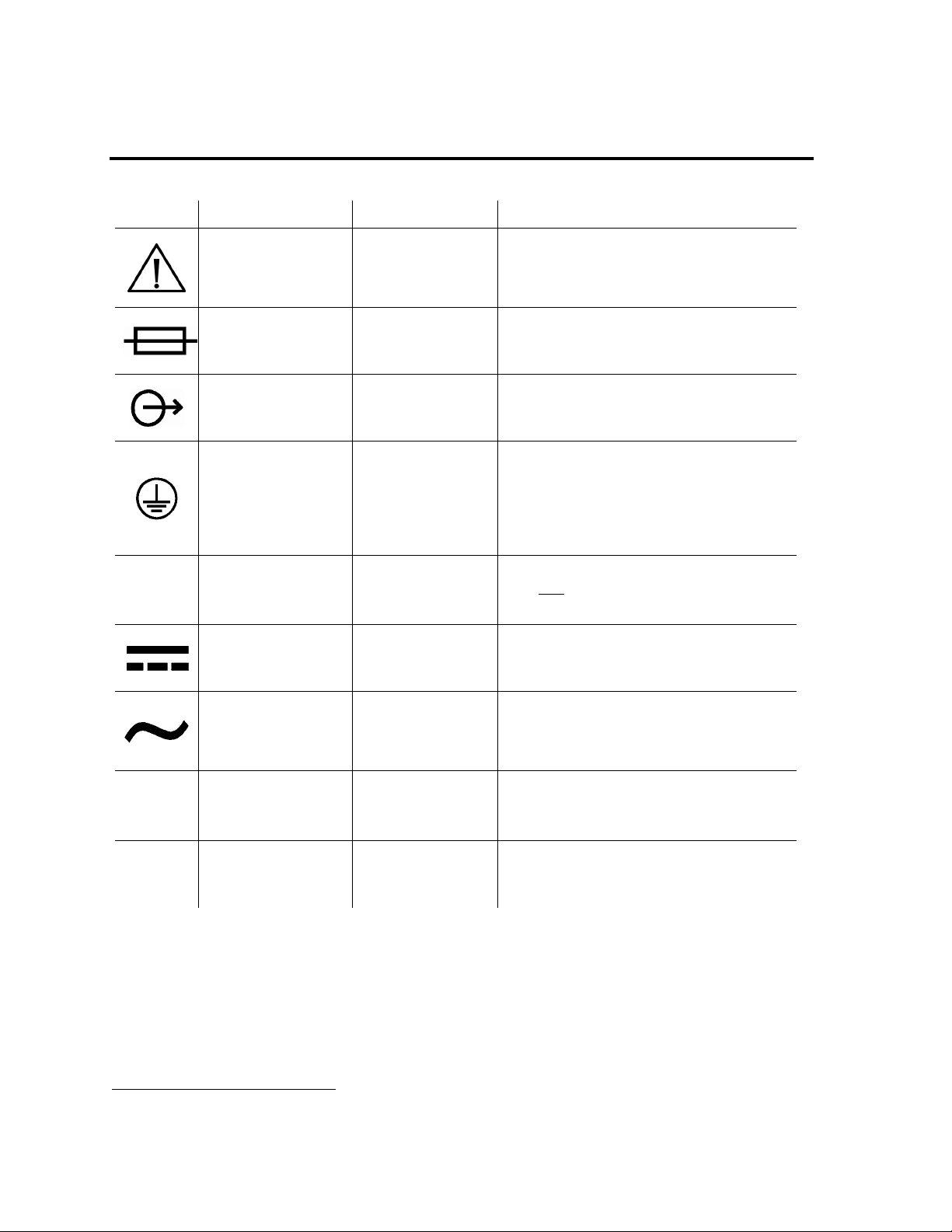
Symbols
Symbol Compliance
4
Title Application
(Prev. IEC 348)
Symbol No.B.3.1
IEC 417
ISO 3864
Symbol No.
417-IEC-5016
IEC 417
Symbol No.
417-IEC-5035
IEC 417
Symbol No.
417-IEC-5019
Caution (refer to
accompanying
documents)
Used to direct the user to the instruction
manual where it is necessary to follow
certain specified instructions where
safety is involved.
Fuse To indicate the fuse boxes, for example,
and their location.
Output To identify an output terminal when it is
necessary to distinguish between inputs
and outputs.
Protective earth
(ground)
To identify any terminal which is
intended for connection to an external
protective conductor for protection
against electric shock in case of a fault
or the terminal of a protective earth
(ground) electrode.
417-IEC-5333
417-IEC-5031
IEC 417
Symbol No.
IEC 417
Symbol No.
Type BF
equipment.
To mark a type BF equipment complying
with IEC
Publication 601.
Direct Current To indicate on the rating plate that the
equipment is suitable for direct current
only; to identify relevant terminals.
Symbol No.
417-IEC-5032
IEC 417
Alternating current To indicate on the rating plate that the
equipment is suitable for alternating
current only; to identify relevant
terminals.
IEC 417
Symbol No.
417-IEC-5172
IEC 60417
Symbol No. 5182
Class II equipment To identify equipment meeting safety
requirements specified for Class II
equipment.
Sound; audio Used to identify controls or terminals
related to audio signals.
4
Reference IEC Medical Electrical Equipment, 2nd. Edition 1988
Page 1-18 LTV® Series ventilator Operator’s Manual
p/n 10664, Rev. T
Page 30

Chapter 2 -
The LTV® Series ventilator is a lightweight, high performance ventilator that is designed to provide the
maximum functionality in the smallest possible package. The LTV
V
ENTILATOR OVERVIEW
®
Series ventilator provides the
following features:
• High performance ventilation in a small lightweight package (10” x 12” x 3”, 13.4 lbs).
®
• Turbine technology allows the LTV
Series ventilator to operate without an external compressed gas
source.
5
• CPAP
• NPPV
, SIMV6, Control, Assist / Control and Apnea Backup ventilation modes.
7
mode ventilation, providing an alarm package suitable for mask ventilation of patients that do
not require life support ventilation.
• Volume Control, Pressure Control (optional) and Pressure Support ventilation.
• Variable alarm settings including High Peak Pressure, Low Peak Pressure, Low Minute Volume,
Apnea, High Breath Rate, and High PEEP.
• Oxygen Blending from a High-Pressure Oxygen source, Low-Pressure Oxygen Bleed-in, O
and O
LTV
Cylinder Duration Monitoring on the LTV® 1000, and Low-pressure Oxygen Bleed-in on the
2
®
950 and 900.
Flush,
2
• Lockable front panel controls.
• Monitors for Breath Rate (f), I:E Ratio, MAP, Minute Ventilation (VE), PEEP, PIP and Tidal Volume
(Vte).
• Real-time patient circuit pressure display with Peak Inspiratory Pressure indicator.
• Variable termination conditions for Pressure Support breaths, including maximum inspiratory time
termination and percentage of peak flow.
• Selectable Percentage of Peak Flow termination for Pressure Control breaths.
• Leak Compensation to improve triggering when a circuit leak is present.
• Single or dual tone output capabilities.
• Operation from a variety of power sources including AC power, internal battery and external DC
power sources.
Intended Use
The LTV® Series ventilator is a restricted medical device designed for use by adults and pediatrics
weighing a minimum of 5 kg (11 lbs), needing Positive Pressure ventilation (delivered invasively or
non-invasively). It is:
• Suitable for service in institutional, homecare and transport settings as a source of continuous or
intermittent ventilatory support.
• Intended for operation only by Respiratory Therapists or other properly trained and qualified
personnel under the direction of a physician and in accordance with applicable state laws and
regulations.
• Pulmonetic Systems Inc. does not recommend that the LTV
its intended use.
5
Continuous Positive Pressure Ventilation
6
Synchronized Intermittent Mandatory Ventilation
7
Non-invasive Positive Pressure Ventilation
Operator’s Manual LTV® Series ventilator Page 2-1
p/n 10664, Rev. T
®
Series ventilator be used outside of
Page 31

Power/Supplies Required
®
To operate the LTV
Series ventilator, you will need the following:
• Power source: Pulmonetic Systems P/N 10537, 110V or 220V AC power source, or
11V to 15V DC power source. This may be an external battery or a
DC power system
8
.
• Oxygen supply: High-pressure oxygen source providing between 40 PSIG and 80 PSIG, or
Low-flow, low-pressure oxygen source providing less than 10 PSIG.
WARNING
Untrained Personnel – Only properly trained personnel should operate the ventilator. The LTV®
Series ventilator is a restricted medical device designed for use by Respiratory Therapists or o t her
properly trained and qualified personnel under the direction of a physician and in accordan ce with
applicable state laws and regulations.
Patient Monitoring - Patients who are dependent on a ventilator should be constantly monitored by
qualified personnel. Such personnel should be prepared to address equipment malfunctions and
circumstances where equipment becomes inoperative. An alternative method of ventilation should be
available for all patients dependent on the ventilator, and qualified personnel should be fully familiar
with emergency ventilation procedures.
AVERTISSEMENT
Personnel non qualifié - Seul le personnel qualifié doit opérer le ventilateur. Le ventilateur de la
série LTV® est un dispositif médical restreint conçu pour être utilisé par les inhalothérapeutes ou
autres personnes qualifiées, et par le personnel qualifié sous la supervision d'un médecin et en
conformité avec les lois et règlements applicables.
Surveillance du patient – Un personnel qualifié doit constamment surveiller les patients qui sont
reliés à un ventilateur. Le personnel doit être en mesure de s’occuper des défectuosités de
fonctionnement de l’équipement ainsi que des circonstances où ce dernier devient inopérant. Une
forme de ventilation alternative doit être disponible à tous les patients reliés au ventilateur et le
personnel qualifié devrait être pleinement familier avec les procédures de ventilation d’urgence.
8
Airline carriers typically allow only dry cell batteries on board aircraft. However, some airlines may allow an
electrical cord to be plugged in if arranged in advance. Pulmonetic Systems recommends checking with the
intended carrier well in advance before traveling.
Page 2-2 LTV® Series ventilator Operator’s Manual
p/n 10664, Rev. T
Page 32

Information/Assistance
For additional information or troubleshooting assistance concerning the operation of the LTV
ventilators, contact a certified Pulmonetic Systems’ service technician or:
Pulmonetic Systems, Inc.
17400 Medina Rd., Suite 100
Minneapolis, Minnesota 55447-1341
Phone: (763) 398-8300
Customer Care Center: (800) 754-1914
Fax: (763) 398-8400
E-mail: [email protected]
Website: http://www.pulmonetic.com
®
Series
Operator’s Manual LTV® Series ventilator Page 2-3
p/n 10664, Rev. T
Page 33

Page 2-4 LTV® Series ventilator Operator’s Manual
p/n 10664, Rev. T
Page 34

Chapter 3 -
This chapter contains information regarding the breath types available on the LTV® Series ventilator.
It covers how breaths are initiated, limited and cycled, and when each type of breath is given.
The following terms are used in discussing how breaths are given:
Initiate
Limit
Cycle
What causes a breath to be given. Breaths may be initiated by a patient trigger, a
push of the manual breath button, or by the ventilator based on the set breath rate
and ventilation mode.
How the breath is controlled. Breaths may be limited to a maximum circuit pressure
or flow.
What causes the breath to be cycled from the inspiratory phase to the exhalation
phase. Breaths may be cycled by the ventilator when a set time or delivered volume
has been reached, or when an alarm condition such as a high pressure limit has
been reached. Spontaneous breaths are terminated when the flow based on patient
demand decreases to 10% of the maximum flow delivered during the breath, or
below 3 Lpm.
B
REATH TYPES
Breath Types
Breaths are defined by how they are initiated, limited and cycled. The breath types are Machine,
Assist, and Patient.
Machine
Initiated By - Ventilator Patient Patient
Limited By - Ventilator Ventilator Ventilator
Cycled By - Ventilator Ventilator Patient
Breaths may be given in any of the following forms: Volume Control, Pressure Control, Pressure
Support and Spontaneous. These breaths are given as described in the sections below.
In addition, the following parameters apply to all breaths:
• The Minimum Inspiratory Time is 300 ms.
• The Minimum Exhalation Time is 346 ms.
• When patient triggers are enabled, triggers are detected during exhalation after the Minimum
Exhalation Time has expired.
Assist Patient9
9
Pressure Support or Spontaneous
Operator’s Manual LTV® Series ventilator Page 3-1
p/n 10664, Rev. T
Page 35

Volume Control Breaths
For Volume Control breaths, the set Tidal Volume is delivered over the set Inspiratory Time and flow
is delivered in a decelerating taper flow waveform. Peak flow is calculated based on the Tidal Volume
and Inspiratory Time and the final flow is 50% of the peak flow. Volume breaths may be machine or
assist type breaths.
When the combination of inspiratory time and tidal volume result in an initial flow of <20 Lpm, the final
flow remains at 10 lpm and the waveform is flattened.
Page 3-2 LTV® Series ventilator Operator’s Manual
p/n 10664, Rev. T
Page 36

Pressure Control Breaths
For Pressure Control breaths
Control setting and maintain it at that pressure for the set Inspiratory Time. Pressure Control breaths
may be machine or assist type breaths.
10
, flow is delivered to elevate the circuit pressure to the Pressure
Adjusting the Rise Time Profile changes the flow and pressure waveforms for Pressure Control
breaths.
Operator’s Manual LTV® Series ventilator Page 3-3
p/n 10664, Rev. T
Page 37

Pressure Control Breaths (cont)
Pressure Control breaths have an optional flow termination criteria. If PC Flow Termination is on
Pressure Control breaths may be time or flow terminated. If the flow drops to the set FLOW TERM
level before the inspiratory time is completed, the inspiration is cycled.
10
Pressure Control and Pressure Support breaths do not compensate for PEEP. Delivered pressure is controlled
by the Pressure Control setting and is not affected by the PEEP setting. i.e.; A Pressure Control setting of
20cmH
Page 3-4 LTV® Series ventilator Operator’s Manual
p/n 10664, Rev. T
O and a PEEP setting of 10cmH2O results in a maximum delivered pressure of 20cmH2O.
2
Page 38

Pressure Support Breaths
For Pressure Support breaths, flow is delivered to elevate the circuit pressure to the Pre ssure
Support setting and maintain it at that pressure until the flow drops below a variable percentage of the
peak flow. Pressure Support breaths may also be cycled by a variable time limit, or by exceeding 2
breath periods. Pressure support breaths are patient type breaths.
For some patients, it may be useful to adjust the variable flow termination percentage. Adjusting the
FLOW TERM setting between 10% and 40% will change the length, volume and comfort of the
inspiration.
Operator’s Manual LTV® Series ventilator Page 3-5
p/n 10664, Rev. T
Page 39

Spontaneous Breaths
For Spontaneous breaths, flow is delivered to meet patient demand and maintain the circuit pressure
at the measured PEEP from the previous breath. The breath is cycled when the flow drops below
10% of the maximum flow delivered during the breath, or below 3 lpm. Spontaneous breaths may
also be terminated by exceeding 2 breath periods. Spontaneous breaths are patient type breaths.
WARNING
Accuracy of PEEP setting - Variations in the patient’s breathing pattern and/or leaks in the patient
circuit (including leaks around the tracheostomy tube cuff) can affect PEEP. PSI recommends that the
clinician set the PEEP to the prescribed level on a test lung while observing the PEEP value in the
LTV display window. The clinician should also periodically monitor the PEEP value in the LTV display
window. Using an inaccurate PEEP setting due to a patient leak can result in less than prescribed
PEEP or undesirable increases in patient circuit pressure when the patient circuit leak changes.
AVERTISSEMENT
Exactitude du paramètre PEP – Les écarts dans le mode de respiration du patient et/ou les fuites
du circuit du patient (y compris les fuites autour du ballonnet pour canule de trachéostomie) peuvent
affecter le PEP. Des études et investigations préliminaires recommandent que le clinicien définisse le
PEP au niveau prescrit sur un poumon d’essai tout en observant la valeur PEP de l’écran graphique
LTV. Le clinicien doit par ailleurs surveiller de façon périodique la valeur PEP de l’écran graphique
LTV. L’utilisation d’un paramètre PEP inapproprié en raison d’une fuite de patient peut
potentiellement résulter en un paramètre inférieur au paramètre PEP prescrit ou en une
augmentation indésirable de la pression du circuit du patient lorsque la fuite du circuit du patient
change
Page 3-6 LTV® Series ventilator Operator’s Manual
p/n 10664, Rev. T
Page 40

Chapter 4 -
V
ENTILATION MODES
The LTV
• Control
• Assist/Control
• SIMV - Synchronized Intermittent Mandatory Ventilation
• CPAP - Continuous Positive Airway Pressure
• Apnea Backup Ventilation
• NPPV - Non-Invasive Positive Pressure Ventilation
Each of these modes is described below.
®
Series ventilator provides the following modes of ventilation:
Control Mode
Control mode ventilation is selected when Assist / Control is selected and Sensitivity is set to
dashes “- - -”. In Control mode, Volume or Pressure Controlled machine breaths are given at the rate
specified by the Breath Rate setting and no triggered breaths are allowed.
Assist/Control Mode
Assist / Control ventilation is selected when Assist / Control is selected and Sensitivity is on. In
Assist / Control mode, the ventilator guarantees a minimum number of Volume or Pressure Controlled
breaths are given. The patient may trigger additional Volume or Pressure Controlled assist breaths.
Operator’s Manual LTV® Series ventilator Page 4-1
p/n 10664, Rev. T
Page 41
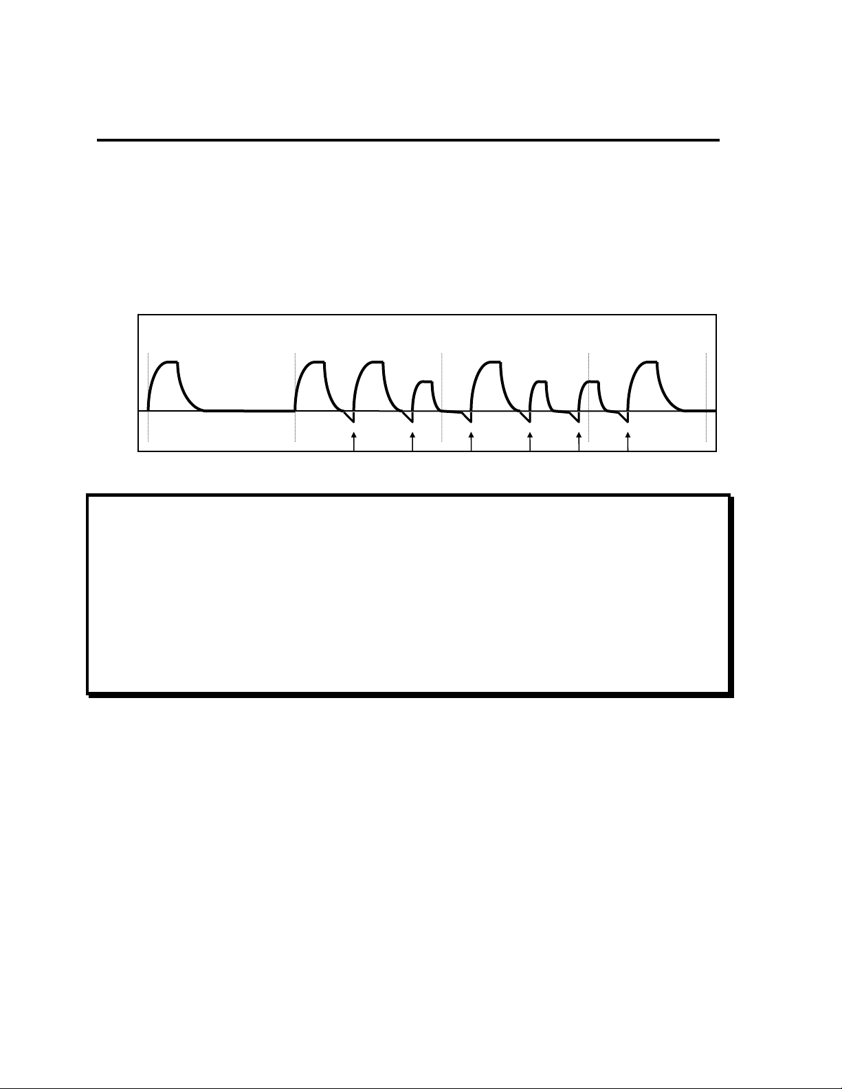
SIMV Mode
SIMV mode is selected when SIMV / CPAP is selected and Breath Rate is set between 1 and 80. In
SIMV mode, machine, assist and patient breaths may be given.
For the first patient trigger detected within a breath period, an assist breath is given. For all
subsequent patient triggers within the same breath period, spontaneous patient breaths are given.
At the beginning of a breath period, if no triggered breaths were given in the previous breath period, a
machine breath is given. If there was a patient trigger in the previous breath cycle, the ventilator will
not give a machine breath in the current breath period unless the set Apnea Interval is exceeded.
Paw
Machine Machine Assist Assist Assist Pressure
Support
Patient Triggers
Pressure Control Machine and Assist Breaths, and Pressure Support Patient Breaths
Pressure
Support
Pressure
Support
NOTE
LTV® ventilators provide an Apnea Backup mode of ventilation. When the set Apnea Interval
(maximum time allowed between the beginning of one breath and the beginning of the next breath) is
exceeded, the APNEA alarm is generated and the ventilator will enter Apnea Backup ventilation
mode.
REMARQUE
Les ventilateurs LTV® procurent un mode de ventilation de secours pour l’apnée. Lorsque l’intervalle
de l’apnée établi (durée maximum allouée entre le début d’une respiration et le début de la respiration
suivante) est excédé, l’alarme APNEA est générée et le ventilateur entre en mode de ventilation de
secours pour l’apnée.
Page 4-2 LTV® Series ventilator Operator’s Manual
p/n 10664, Rev. T
Page 42
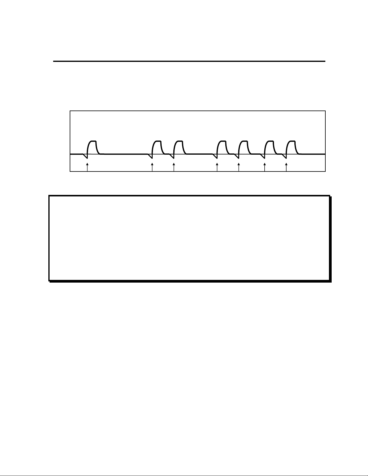
CPAP Mode
CPAP mode is selected when SIMV / CPAP is selected and Breath Rate is set to dashes “—”. In
CPAP mode, when a patient trigger is detected, a patient breath is given. Breaths will be Pressure
Support or Spontaneous breaths according to the Pressure Support setting.
Pressure
Support
Pressure
Support
Pressure
Support
Pressure
Support
Pressure
Support
Pressure
Support
Pressure
Support
Paw
Patient Triggers
Pressure Support Patient Breaths
NOTE
LTV® ventilators provide an Apnea Backup mode of ventilation. When the set Apnea Interval
(maximum time allowed between the beginning of one breath and the beginning of the next breath) is
exceeded, the APNEA alarm is generated and the ventilator will enter Apnea Backup ventilation
mode.
REMARQUE
Les ventilateurs LTV® procurent un mode de ventilation de secours pour l’apnée. Lorsque l’intervalle
de l’apnée établi (durée maximum allouée entre le début d’une respiration et le début de la respiration
suivante) est excédé, l’alarme APNEA est générée et le ventilateur entre en mode de ventilation de
secours pour l’apnée.
Operator’s Manual LTV® Series ventilator Page 4-3
p/n 10664, Rev. T
Page 43

Apnea Backup
The LTV
begins when the time since the last breath start is greater than the set Apnea Interval.
When an apnea alarm occurs:
• If an inspiration is in progress, the ventilator cycles to exhalation.
• The ventilator begins Apnea Backup ventilation in the Assist/Control mode according to the
The breath rate for Apnea Backup mode is determined as follows:
• If the set Breath Rate is ≥ = 12 bpm, the Apnea breath rate is the set Breath Rate.
• If the set Breath Rate is < 12 bpm and the set Breath Rate is not limited by other control settings,
• If the set Breath Rate is limited to <12 bpm, the Apnea breath rate is the highest allowed rate.
The ventilator exits Apnea Backup mode and returns to the previous mode of ventilation when the
operator resets the Apnea alarm or when two consecutive patient-initiated breaths occur.
The Apnea Interval may be changed using the Extended Features menu.
®
Series ventilator provides an Apnea Backup mode of ventilation. Apnea Backup ventilation
current control settings. The active controls are displayed at full intensity, and all other controls
are dimmed.
the Apnea breath rate is 12 bpm.
Page 4-4 LTV® Series ventilator Operator’s Manual
p/n 10664, Rev. T
Page 44

NPPV
The ventilator provides Non-invasive Positive Pressure Ventilation (NPPV) as a secondary
mode that may be selected in addition to the primary ventilation mode. When NPPV mode is
selected, ventilation is delivered according to the selected mode, however, a modified set of alarms
are active. NPPV is selected using the Extended Features menu and is not selectable from the front
panel controls. While the ventilator is operating in NPPV mode, the NPPV LED is lit.
In NPPV mode, only the following alarms are active:
• High Pressure • Apnea Alarm and Apnea Backup ventilation
• Sense Line Disconnect • External Power Lost
• Internal Battery Low • Internal Battery Empty
• Vent Inop • Defaults
All other alarms are disabled. The displays for Low Minute Volume and Low Peak Pressure are set
to dimmed dashes indicating they are not available.
WARNING
NPPV Mode - NPPV11 is not a life support mode and is not suitable for patients that require life
support ventilation. NPPV Mode should only be used for supplemental ventilation of non-life support
patients.
NPPV Mode - When operating in NPPV11 mode, many of the standard alarms are disabled. This may
result in reduced ventilation accuracy should a problem occur. Carefully read Chapter 4 - Ventilation
Modes,
NPPV, before selecting this mode of operation.
AVERTISSEMENT
Mode NPPV – Le mode NPPV n’est pas un mode de maintien des fonctions vitales continu et il n’est
pas approprié pour les patients qui ont besoin d’une ventilation continue pour le maintien des
fonctions vitales. Le mode NPPV ne doit être utilisé que comme ventilation supplémentaire pour les
patients qui ne nécessitent pas de maintien des fonctions vitales.
Mode NPPV – Lorsque l’appareil fonctionne en mode NPPV, bon nombre des alarmes standards
sont désactivées. Par conséquent, si un problème survient, la précision de la ventilation pourrait
diminuer. Assurez-vous de lire attentivement le chapitre 4 – Types de respiration et modes de
ventilation, mode NPPV avant de choisir ce mode de fonctionnement.
11
Non-Invasive Positive Pressure
Operator’s Manual LTV® Series ventilator Page 4-5
p/n 10664, Rev. T
Page 45

Volume / Pressure Ventilation
The LTV® Series ventilator offers both Volume and Pressure ventilation.
When Volume is selected, all machine and assist breaths are Volume Control breaths. Breath s are
given according to the Tidal Volume and Inspiratory Time controls. For more information on Volume
Control breaths, see Chapter 6 - Controls, Tidal Volume.
When Pressure is selected, all machine and assist breaths are Pressure Control breaths. Breaths
are given according to the Pressure Control and Inspiratory Time controls. For more information on
Pressure Control breaths, see Chapter 6 - Controls,
Pressure
Control.
Bias Flow
The LTV® Series ventilator provides a constant bias flow of 10 Lpm during exhalation to assist with
patient triggering.
Page 4-6 LTV® Series ventilator Operator’s Manual
p/n 10664, Rev. T
Page 46

Chapter 5 -
U
SING THE CONTROLS AND INDICATORS
Ventilator Controls
The following diagram shows how the front panel controls and displays are arranged. This illu stration
shows the LTV
Inspiratory / Expiratory Hold are not available on some models.
®
1000. Pressure Control ventilation, Oxygen Blending, O2 Flush (O2% (O2 Flush)) and
Operator’s Manual LTV® Series ventilator Page 5-1
p/n 10664, Rev. T
Page 47

Setting a Control
®
There are 5 kinds of controls on the LTV
Series ventilator. They are:
Variable Controls
Buttons
Set Value Knob
Controls and alarms that have front panel displays.
Push buttons that select an option or perform a function.
Used to set control values and navigate extended features
menus.
Extended Features
Ventilation options that do not have front panel controls but are
available through a special menu.
Mechanical Controls
Controls such as PEEP that are set by mechanical means.
The following sections describe how to set each kind of control.
Variable Controls
To set a variable control:
1) Select the control by pushing the associated button. The display for the selected control will be
displayed at normal brightness, but the remaining control displays will dim.
2) Change the control value by rotating the Set Value Knob. Rotate clockwise to increase and
counter-clockwise to decrease the value. Turning the control knob slowly will change the setting
by a small increment. Turning the control knob more quickly will change the setting by a larger
increment.
3) Deselect the control by:
• Waiting 5 seconds, or
• Pushing the selected button again, or
• Selecting another control, or
• Pushing the Control Lock button
When the control is deselected, all displays will return to their normal brightness. The new control
value goes into effect as soon as the control is deselected.
Page 5-2 LTV® Series ventilator Operator’s Manual
p/n 10664, Rev. T
Page 48

Buttons
Button controls do one of three things:
• Turn a feature on or off, such as Control Lock.
• Toggle between two features, such as Volume or Pressure ventilation.
• Perform a function, such as Manual Breath.
Push the button to activate the feature or change the feature state. A green LED next to the button
indicates when a feature is on.
For Mode buttons, there is a second confirmation push required. To toggle between modes:
1) Push the mode button. The associated LED will flash for 5 seconds.
2) To confirm the mode change, push the mode button again while the LED is flashing. The
ventilator will begin operating in the new mode.
To prevent an accidental shutdown, the ventilator requires a longer push of the On / Standby button
to put the ventilator in the Standby state. To put the ventilator in Standby, push and hold the On /
Standby button for 3 seconds.
Set Value Knob
Use the Set Value Knob to set control values and navigate extended features menus.
To change the setting for a variable control, select the control then turn the knob clockwise or
counter-clockwise until the desired setting is reached.
For information on how to use the Set Value Knob to navigate the extended features menus, see
Chapter 10 - Extended Features.
Extended Features
The Extended Features menus allow you to set ventilation parameters that do not have dedicated
front panel controls. For information on how to use the Set Value Knob to navigate the extended
features menus, see Chapter 10 - Extended Features.
Operator’s Manual LTV® Series ventilator Page 5-3
p/n 10664, Rev. T
Page 49

Mechanical Controls
The ventilator PEEP setting is a manually adjusted mechanical control. Instructions for setting this
control are given in Chapter 6 - Controls.
WARNING
Accuracy of PEEP setting - Variations in the patient’s breathing pattern and/or leaks in the patient
circuit (including leaks around the tracheostomy tube cuff) can affect PEEP. PSI recommends that the
clinician set the PEEP to the prescribed level on a test lung while observing the PEEP value in the
LTV display window. The clinician should also periodically monitor the PEEP value in the LTV display
window. Using an inaccurate PEEP setting due to a patient leak can result in less than prescribed
PEEP or undesirable increases in patient circuit pressure when the patient circuit leak changes.
AVERTISSEMENT
Exactitude du paramètre PEP – Les écarts dans le mode de respiration du patient et/ou les fuites
du circuit du patient (y compris les fuites autour du ballonnet pour canule de trachéostomie) peuvent
affecter le PEP. Des études et investigations préliminaires recommandent que le clinicien définisse le
PEP au niveau prescrit sur un poumon d’essai tout en observant la valeur PEP de l’écran graphique
LTV. Le clinicien doit par ailleurs surveiller de façon périodique la valeur PEP de l’écran graphique
LTV. L’utilisation d’un paramètre PEP inapproprié en raison d’une fuite de patient peut
potentiellement résulter en un paramètre inférieur au paramètre PEP prescrit ou en une
augmentation indésirable de la pression du circuit du patient lorsque la fuite du circuit du patient
change
Page 5-4 LTV® Series ventilator Operator’s Manual
p/n 10664, Rev. T
Page 50

Bright, Dim and Blank Control Displays
Variable controls will be displayed at normal or dimmed intensity, or may be blanked. A display will be
displayed at normal intensity:
• When it is selected for change. All other displays will be dimmed.
• When it is active in the current ventilation mode. Dimmed displays are not active in the current
mode.
NOTE
Be sure to set any controls that may be used in Apnea Backup ventilation to appropriate values. Even
though these controls are dimmed, they will be used if apnea should occur.
REMARQUE
Assurez-vous de régler aux valeurs appropriées, tous les contrôles susceptible s d'être utilisés en
mode ventilation de secours pour l'apnée. Même si ces contrôles sont en veilleuse, ils seront utilisés
en cas d'apnée.
A display will be displayed at dimmed intensity:
• When another control is selected for change.
• When it is not active in the current ventilation mode.
A display will be blank:
• To conserve battery power while operating from battery power:
• If no button pushes or control knob activity occurs for 60 seconds, the displays are turned off. The
display window, 7-segment control displays, and LEDs are turned off. Anytime an alarm occurs,
or if an alarm message is already displayed, the display window will remain active. The Airway
Pressure display is always active.
• To turn the displays back on, push any button or turn the control knob.
• When an option, such as oxygen blending, is not installed.
• When a control feature is not available, such as during Ventilator Checkout tests.
Operator’s Manual LTV® Series ventilator Page 5-5
p/n 10664, Rev. T
Page 51

Flashing Controls
Variable controls and alarms will be displayed solid or flashing. A flashing control means one of the
following things:
• If you are changing a control setting, and the display flashes, you have reached a limited value for
the control. Control Limiting is covered later in this section.
• If an alarm display flashes, it indicates that an alarm has occurred or is occurring. See Chapter 9 Ventilator Alarms for more information on this.
• If a control display flashes, it indicates a special condition such as time termination of a pressure
support breath. For more information, see Chapter 6 - Controls.
• If the Control Lock LED flashes, it indicates you have tried to change the control settings while
the front panel controls are locked. For more information, see Chapter 6 - Controls, Control Lock.
Dashes
If a control display is set to dashes “ - - - ”, it indicates that control is turned off, or is not available in
the current ventilation mode.
Control Limiting
Variable control settings may be limited to less than their specified range for any of the following
reasons:
• To prevent inverse I:E ratios of greater than 4:1
• To ensure a minimum inspiration time of 300 ms
• To ensure a minimum exhalation time of 346 ms
• To ensure a minimum initial flow of 10 lpm for Volume Controlled breaths
• To ensure a maximum initial flow of 100 lpm for Volume Controlled breaths
When you are updating a control and have reached a limited condition, the following things happen:
• The control stops updating and will remain displayed at the highest (or lowest) allowed value.
• The control display will flash.
• The displays for other controls involved in the limited condition will flash.
To set the control to a value outside the limited range, you will need to change the settings for other
controls involved in the limit condition. For instance, if the Breath Rate is set to 12, the maximum
allowed Inspiratory Time is 4.0 seconds. To set the Inspiratory Time to more than 4.0 seconds, you
must first decrease the Breath Rate.
Page 5-6 LTV® Series ventilator Operator’s Manual
p/n 10664, Rev. T
Page 52

Control Locking
The front panel controls may be locked so that settings cannot be accidentally changed. When the
controls are locked, the Control Lock LED will be on. If you try to select or change a control while the
Control Lock is on, the message LOCKED will be displayed in the display window and the Control
Lock LED will flash.
Two different levels of difficulty can be set for control unlocking: Easy and Hard. The Easy unlocking
method should be used when only trained personnel have access to the ventilator. The Hard method
should be used when children or others may have access to the ventilator and you want to prevent
accidental changes to the control settings. Easy unlocking is the default and this setting is changed
using the Extended Features menus
To turn the Control Lock on:
1) Push the Control Lock button.
The Control Lock LED is on whenever the front panel controls are locked.
If you push a button while the controls are locked:
1) The Control Lock LED will flash.
2) LOCKED will be displayed in the display window.
3) The button push is ignored.
To turn the Control Lock off with Easy unlocking:
1) Push the Control Lock button.
To turn the Control Lock off with Hard unlocking:
1) Push and hold the Control Lock button for 3 seconds.
These controls are not affected by the control lock and operate even when the control lock is on:
Manual Breath, Silence / Reset, Select.
12
.
Control Retention
Once a control value is set, that value will be retained in non-volatile memory13. The settings retained
in non-volatile memory will be used when the ventilator is next powered up.
12
See Chapter 10 - Extended Features, Control Unlock for more information.
13
Non-volatile memory is memory that is not erased when the ventilator is turned off or disconnected.
Operator’s Manual LTV® Series ventilator Page 5-7
p/n 10664, Rev. T
Page 53

Page 5-8 LTV® Series ventilator Operator’s Manual
p/n 10664, Rev. T
Page 54

Chapter 6 -
This section explains how each of the LTV® Series ventilator front panel controls work.
C
ONTROLS
Assist/Control / SIMV/CPAP Modes
This button toggles between Assist/Control and SIMV/CPAP modes of ventilation.
To toggle between the modes:
1) Push the mode button. The associated LED will flash for 5 seconds.
2) To confirm the mode change, push the mode button again while the LED is flashing. The
ventilator will begin operating in the new mode as soon as the mode change is complete.
NOTE
When Assist/Control is selected, the ventilator will be in Control or Assist/Control mode, depending
on the Sensitivity setting.
• If Sensitivity is set to dashes “- - -”, the ventilator will be operating in Control mode.
• If Sensitivity is set to any other value, the ventilator will be operating in Assist/Control mode.
When SIMV/CPAP is selected, the ventilator will be in SIMV or CPAP mode, depending on the Breath
Rate setting.
• If Breath Rate is set to dashes “- -”, the ventilator will be operating in CPAP mode.
• If Breath Rate is set to any other value, the ventilator will be operating in SIMV mode.
REMARQUE
Lorsque Aide / Contrôle est sélectionné, le ventilateur sera en mode Contrôle ou Aide, selon le
réglage de la sensibilité.
• Si la sensibilité est réglée sur Traits « - - - », le ventilateur fonctionnera en mode Contrôle.
• Si la sensibilité est réglée sur toute autre valeur, le ventilateur fonctionnera en mode Aide /
Contrôle.
Lorsque le mode SIMV / CPAP est sélectionné, le ventilateur sera en mode SIMV ou CPAP, selon le
réglage du débit respiratoire.
• Si le débit respiratoire est réglé sur Traits « - - », le ventilateur fonctionnera en mode CPAP.
• Si le débit respiratoire est réglé sur toute autre valeur, le ventilateur fonctionnera en mode SIMV.
Operator’s Manual LTV® Series ventilator Page 6-1
p/n 10664, Rev. T
Page 55

Breath Rate
Use the Breath Rate control to establish the minimum rate of machine or assist breaths that the
ventilator will deliver per minute.
To set the Breath Rate:
1) Push the Breath Rate button.
2) Change the setting using the Set Value knob.
Range: “- -”, 1 - 80 bpm
NOTE
When SIMV/CPAP is selected, the ventilator will be in SIMV or CPAP mode, depending on the Breath
Rate setting.
• If Breath Rate is set to dashes “- -”, the ventilator will be operating in CPAP mode.
• If Breath Rate is set to any other value, the ventilator will be operating in SIMV mode.
REMARQUE
Lorsque le mode SIMV / CPAP est sélectionné, le ventilateur sera en mode SIMV ou CPAP, selon le
réglage du débit respiratoire.
• Si le débit respiratoire est réglé sur Traits « - - », le ventilateur fonctionnera en mode CPAP.
• Si le débit respiratoire est réglé sur toute autre valeur, le ventilateur fonctionnera en mode SIMV.
Page 6-2 LTV® Series ventilator Operator’s Manual
p/n 10664, Rev. T
Page 56

Control Lock
The LTV® Series ventilator front panel controls may be locked so that settings are not accidentally
changed. Two different levels of difficulty can be set for control unlocking: Easy and Hard. Easy
unlocking is the default and this setting is changed using the Extended Features menus
information on using the Control Lock, see Chapter 5 - Control Locking.
To turn the Control Lock on:
1) Push the Control Lock button.
The Control Lock LED is on whenever the front panel controls are locked.
To turn the Control Lock off with Easy unlocking:
1) Push the Control Lock button.
To turn the Control Lock off with Hard unlocking:
1) Push and hold the Control Lock button for 3 seconds.
These controls are not affected by the control lock and operate even when the control lock is on:
Manual Breath, Silence / Reset, Select.
14
. For more
14
See Chapter 10 - Extended Features, Control Unlock for more information.
Operator’s Manual LTV® Series ventilator Page 6-3
p/n 10664, Rev. T
Page 57

High Pressure Limit
Use the High Pressure Limit to establish the maximum pressure permitted the patient circuit. When
this limit is reached:
• A HIGH PRES alarm is displayed
• The audible alarm is sounded
• Inspiration is terminated and exhalation begins
The turbine is stopped to allow the circuit pressure to evacuate when the high pressure condition
persists for more than four times the set inspiratory time or more than 3.0 seconds, whichever is less.
To set the High Pressure Limit:
1) Push the High Pressure Limit button.
2) Change the setting using the Set Value knob.
Range: 5 - 100 cmH
O
2
Page 6-4 LTV® Series ventilator Operator’s Manual
p/n 10664, Rev. T
Page 58

Inspiratory / Expiratory Hold
Pushing the Insp/Exp (Inspiratory/Expiratory) Hold control button causes the ventilator to toggle
between the following messages in the display window. Each push causes the next item in sequence
to be displayed:
INSP HOLD
EXP HOLD
Normal monitor display
While INSP HOLD or EXP HOLD is displayed:
• The Insp/Exp Hold control button LED will flash on and off.
• If the Insp/Exp Hold control button is not pushed within 60 seconds, the message will be
removed and the LED will turn off.
• Pushing the Select, Silence / Reset or Control button will return the display to normal and the
LED will stop flashing.
Operator’s Manual LTV® Series ventilator Page 6-5
p/n 10664, Rev. T
Page 59

Inspiratory Hold
An Inspiratory Hold maneuver holds the inspiratory phase of a delivered breath for a duration
sufficient to determine ∆ Pres pressure and static lung compliance of the patient.
To perform the Inspiratory Hold maneuver:
1) Push the Insp/Exp (Inspiratory/Expiratory) Hold control button once
and the display window will
toggle from normal monitor display to INSP HOLD.
2) Push and hold the Insp/Exp (Inspiratory/Expiratory) Hold button during a volume inspiration.
• The ventilator will perform an Inspiratory Hold on the next Volume breath.
• P Plat
15
--- will be displayed in the display window.
• All buttons that are not lockable will operate normally.
• All buttons that are lockable will be ignored.
3) Continue holding the button until the Volume inspiration is completed. During the maneuver:
• The exhalation valve will remain closed.
• Flow will be set to 0 LPM.
• P Plat xxx will be displayed in the display window, where xxx is the real time circuit
pressure.
• The breath period will remain in inspiration phase so no breath triggers are allowed.
• DISC/SENSE and HIGH PRES alarms will terminate the maneuver.
4) Release the button when the pressure setting is P Plat (or when 6.0 seconds elapse, whichever
comes first):
• The exhalation valve will be opened and a normal exhalation phase will begin.
• The display will cycle every 2 seconds between ∆ Pres xxx where xxx is the change in
pressure
16
, C Static xxx where xxx is the static compliance17 and
P Plat xxx where xxx is the plateau pressure.
NOTE
Breath period timing and apnea timing will be suspended while the maneuver is performed. As a
result, the apnea alarm will not alarm during the maneuver.
REMARQUE
La synchronisation de la période de respiration et la synchronisation de l’apnée sont interrompues
pendant la manœuvre. Ainsi, l’alarme d’apnée ne se déclenche pas au cours de la manœuvre.
Range: P Plat 0 - 100 cmH
∆ Pres 0 - 100 cmH
C Static 1 – 999 ml/cmH
15
“P Plat” is Plateau pressure reached during Inspiratory Hold maneuver.
16
∆ Pres is calculated as P Plat Pressure – PEEP measured from previous breath.
17
C Static is calculated as Set Delivered Volume / ∆ Pres.
Page 6-6 LTV® Series ventilator Operator’s Manual
p/n 10664, Rev. T
O
2
O
2
O
2
Page 60

NOTE
The ventilator will not perform an Inspiratory Hold maneuver during Pressure Control, Pressure
Support or Spontaneous breaths.
If the button is held during exhalation or any non-volume inspiration:
• The associated LED will be blinking.
• All buttons that are not lockable will operate normally.
• All buttons that are lockable will be ignored.
If the button is released before the inspiration is complete, the display will
return to INSP HOLD.
Once the maneuver is completed, if any buttons are touched or an alarm
occurs, the ∆ Pres, C Static or P Plat display will be cleared.
After 60 seconds, the display will be cleared.
REMARQUE
Le ventilateur n’effectue pas une manœuvre de maintien de l’inspiration au cours du contrôle de
pression, du soutien de pression et de ventilations spontanées.
Lorsque le bouton est maintenu pendant l’exhalation ou toute inspiration sans volume:
• Le LED correspondant demeure allumé en continu.
• Tous les boutons non verrouillables fonctionnent normalement.
• Tous les boutons verrouillables sont ignorés.
Lorsque le bouton est relâché avant la fin de l’inspiration, l’affichage
indique INSP HOLD.
Au terme de la manœuvre, l’actionnement d’un bouton ou le déclenchement d’une alarme entraînent
l’effacement de l’affichage ∆ Pres ou C Static.
L’affichage est effacée après 60 secondes.
Operator’s Manual LTV® Series ventilator Page 6-7
p/n 10664, Rev. T
Page 61

Expiratory Hold
An Expiratory Hold maneuver holds the expiratory phase of a delivered breath for a duration sufficient
to determine the AutoPEEP of a patient.
To perform the Expiratory Hold maneuver:
1) Push the Insp/Exp (Inspiratory/Expiratory) Hold button twice
and the display widow will toggle
from normal monitor display to EXP HOLD.
2) Push and hold the Insp/Exp (Inspiratory/Expiratory) Hold button during a Volume or Pressure
Control exhalation and the ventilator will perform an Expiratory Hold at the end of that exhalation.
• Exhalation will proceed normally with the exhalation valve open and normal bias flow.
• All buttons that are not lockable will operate normally.
• All buttons that are lockable will be ignored.
• The breath will remain in exhalation phase.
• If a Patient Effort is detected, the maneuver will be terminated and the appropriate breath
will be given.
• DISC/SENSE and HIGH PRES alarms will terminate the maneuver.
3) Continue holding the button until P Exp with a numeric value is displayed, or the next breath is
scheduled to begin, either due to Breath Rate or a Manual Breath button push. During the
maneuver:
• The exhalation valve will be closed.
• Flow will be set to 0 LPM.
• P Exp xxx will be displayed in the display window, where xxx is the real time circuit
pressure
18
.
• The breath will remain in expiration phase.
• DISC/SENSE and HIGH PRES alarms will terminate the maneuver.
• If a Patient Effort is detected, the maneuver will be terminated and the appropriate breath
will be given.
4) Release the button (or when 6.0 seconds elapse, whichever comes first):
• A normal inspiration phase will begin.
• AutoPEEP xxx will be displayed where xxx is the autoPEEP
18
.
• Any machine breath starts or apnea alarms that were held off will resume.
NOTE
Breath period timing and apnea timing will be suspended while the maneuver is performed. As a
result, the apnea alarm will not alarm during the maneuver.
REMARQUE
La synchronisation de la période de respiration et la synchronisation de l’apnée sont interrompues
pendant la manœuvre. Ainsi, l’alarme d’apnée ne se déclenche pas au cours de la manœuvre.
Range: P Exp 0 - 100 cmH
AutoPEEP 0 - 100 cmH
18
AutoPEEP is calculated as P Exp at end of Expiratory Hold maneuver minus P Exp at end of normal
exhalation (monitored PEEP).
Page 6-8 LTV® Series ventilator Operator’s Manual
p/n 10664, Rev. T
2
2
O
O
Page 62

NOTE
The ventilator will not perform an Expiratory Hold maneuver during Pressure Support or Spontaneous
breaths.
If the button is held during inspiration or during Pressure Support or spontaneous exhalation:
• The associated LED will be blinking.
• All buttons that are not lockable will operate normally.
• All buttons that are lockable will be ignored.
If the button is released before the expiration is complete, the display will return to EXP HOLD.
Once the maneuver is completed, if any buttons are touched or an alarm occurs, the AutoPEEP
display will be cleared.
After 60 seconds, the AutoPEEP display will be cleared.
REMARQUE
Le ventilateur n’effectue pas une manœuvre de maintien de l’expiration au cours du soutien de
pression ou de ventilations spontanées.
Lorsque le bouton est maintenu pendant l’inspiration, le soutien de pression ou des ventilations
spontanées:
• Le LED correspondant demeure allumé en continu.
• Tous les boutons non verrouillables fonctionnent normalement.
• Tous les boutons verrouillables sont ignorés.
Lorsque le bouton est relâché avant la fin de l’expiration, l’affichage indique EXP HOLD.
Au terme de la manœuvre, l’actionnement d’un bouton ou le déclenchement d’une alarme entraînent
l’effacement de l’affichage AutoPEEP.
L’affichage AutoPEEP est effacée après 60 secondes.
Operator’s Manual LTV® Series ventilator Page 6-9
p/n 10664, Rev. T
Page 63

Inspiratory Time
This control sets the length of the inspiratory period for Volume Controlled and Pressure Controlled
breaths.
The Inspiratory Time setting, along with the Volume Control setting are used to determine the peak
flow for Volume controlled breaths. While the Inspiratory Time is being updated, the Calculated Peak
Flow will be displayed in the display window.
To set the Inspiratory Time:
1) Push the Inspiratory Time button.
2) Change the setting using the Set Value knob.
Range: 0.3 - 9.9 sec
Page 6-10 LTV® Series ventilator Operator’s Manual
p/n 10664, Rev. T
Page 64

Low Minute Volume
The Low Minute Volume alarm sets the minimum expected exhaled Minute Volume. The exhaled
Minute Volume is recalculated after every breath. If the Minute Volume does not meet or exceed the
Low Minute Volume setting:
• A LOW MIN VOL alarm is displayed
• The audible alarm is sounded
The Low Minute Volume alarm is not active in NPPV mode.
To set the Low Minute Volume alarm:
1) Push the Low Minute Volume button.
2) Change the setting using the Set Value knob.
Range: Off, 0.1 - 99 L
WARNING
Low Minute Volume Control Settings - The Low Minute Volume control should be set to its highest
clinically appropriate value. If there is a clinical need to set the Low Minute Volume alarm to lower
values or off (“- - -“), perform a clinical assessment to determine if an alternative monitor (i.e. a Pulse
Oxymeter with an audible alarm, or a Cardio Respiratory Monitor) should be used.
AVERTISSEMENT
Réglages du contrôle de volume bas par minute - Le contrôle du volume bas par minute doit être
ajusté à la plus haute valeur clinique appropriée. Si l’alarme de volume bas par minute doit être
ajustée à des valeurs inférieures ou mise à l’arrêt (“- - -“) p our satisfaire aux besoins cliniques,
effectuer une évaluation clinique afin de déterminer si l’utilisation d’un autre moniteur (c.-à-d.,
sphygmo-oxymètre muni d’une alarme sonore ou un moniteur cardio-respiratoire) s’avère pertinente.
Operator’s Manual LTV® Series ventilator Page 6-11
p/n 10664, Rev. T
Page 65

Low Pressure
The Low Pressure alarm can be set to apply to All breaths or to Volume Control and Pressure
Control breaths only. (For information on selecting breath types, see Chapter 10 - Extended Features,
Low Peak Pressure Alarm.) The Low Pressure alarm establishes the minimum expected circuit
pressure for the selected breath types. If the circuit pressure does not meet or exceed the Low
Pressure setting:
• A LOW PRES alarm is displayed
• The audible alarm is sounded
The Low Pressure alarm is not active in NPPV mode.
To set the Low Pressure alarm:
1) Push the Low Pressure button.
2) Change the setting using the Set Value knob.
Range: “- -”, 1 - 60 cmH
WARNING
Patient Circuit Accessories - The use of accessories such as Speaking Valves, Heat-Moisture
Exchangers and Filters create additional patient circuit resistance and in the event of a disconnectio n,
may impede the generation of a Low Pressure Alarm. Ensure that the Low Pressure Alarm settings
accommodate these types of accessories when used in combination with patient circuits.
2
O
AVERTISSEMENT
Accessoires du circuit du patient - L’utilisation d’accessoires tels que les membrane s vocales, les
échangeurs thermohydriques et les filtres, produit une résistance a dditionnelle dans le circuit de
patient et en cas de débranchement, elle risque d’empêcher la génération de l’al arme de basse
pression. S’assurer que les paramètres de l’alarme de basse pression s’adaptent à ces types
d’accessoires lorsqu’ils sont utilisés avec les circuits du patient.
Page 6-12 LTV® Series ventilator Operator’s Manual
p/n 10664, Rev. T
Page 66

Low Pressure O2 Source (LTV® 1000 Only)
When selected, this option allows oxygen to be supplied from a low pressure / low flow oxygen
source such as an oxygen concentrator or line mounted flow meter. Oxygen from the low pressure
source is mixed with air inside the ventilator. The O
inlet flow and the total minute volume and is not regulated by the ventilator. Use the Input O2
the O
2
Flow chart (page 6-15) to determine the correct O
• When the Low Pressure O
to the ventilator, an Automatic High O
Source option is selected and a high O2 pressure source is attached
2
Switch Over safety response19 generates a HIGH O2
2
PRES alarm, switches the ventilator to High Pressure O
of oxygen to be delivered in the gas flow to 21%.
When the Low Pressure O
Source option is not selected, a high pressure oxygen source is
2
expected, and oxygen blending is done within the ventilator. The ventilator expects an oxygen source
with a pressure of 40 - 80 PSIG. The O
Flush) setting on the ventilator front panel.
(O
2
percent delivered to the patient is determined by the O2 %
2
To toggle the state of the Low Pressure O
1) Push the Low Pressure O
• While the Low Pressure O
Source button.
2
Source is selected, the associated LED will be on.
2
2
While Low Pressure O
Source is on:
2
• The O2 Inlet Pressure Low alarm is inactive.
• The O
• The O
Pressure High alarm is set to activate at > 10 PSIG.
2
% (O2 Flush) display will display dimmed dashes and O2 % cannot be set.
2
• Oxygen inlet flow must be set to obtain the desired oxygen percentage.
percent delivered to the patient is determined by
2
flow for the desired FIO2.
2
Source mode and sets the percentage
2
Source:
WARNING
Inspired Oxygen (FIO2) Concentration – If the patient has a variable respiratory rate, his/her minute
ventilation will fluctuate. If exact concentrations of inspired oxygen (FIO2) are required to be delivered
to the patient, it is recommended that an accurate oxygen analyzer with alarms be used.
AVERTISSEMENT
Concentration d’oxygène inspiré (FIO2) – Si la fréquence respiratoire du patient est variable, sa
ventilation-minute va fluctuer. Lorsqu’une concentration exacte d’oxygène inspiré (FIO2) est
nécessaire pour une transmission au patient, il est recommandé d’utiliser un analyse ur de niveau
d’oxygène2 précis, comportant des alarmes.
19
The Automatic High O2 Switch Over safety response is only available on LTV®1000 ventilators.
Operator’s Manual LTV® Series ventilator Page 6-13
p/n 10664, Rev. T
Page 67

Low Pressure O2 Source (cont.)
NOTE
The Oxygen Inlet High Pressure Alarm at 10 PSIG is only active when Low Pressure O2 Source is on.
REMARQUE
L'alarme de haute pression d'entrée de l'oxygène réglée sur 10 PSIG ne sera active que lorsque la
source de basse pression O2 est activée.
While Low Pressure O
• The O2 Inlet Pressure Low alarm is set to activate at less than 35 PSIG.
• The O
• The O
Pressure High alarm is set to activate at greater than 85 PSIG.
2
% (O2 Flush) may be used to set the desired percentage of oxygen.
2
Source is off:
2
NOTE
The Oxygen Inlet High Pressure Alarm at 85 PSIG and Oxygen Inlet Low Pressure Alarm at 35 PSIG
are only active when Low Pressure O2 Source is off and the O2 % (O2 Flush) setting is greater than
21%.
REMARQUE
L'alarme de haute pression d'entrée de l'oxygène réglée sur 85 PSIG, et l'alarme de basse pression
d'entrée de l'oxygène réglée sur 35 PSIG ne seront actives que lorsque la source de basse pression
O2 est désactivée et que le réglage du O2 % (Flush O2) est supérieur à 21%.
When the Oxygen Blending option is not installed:
The Low Pressure O2 Source button is only active when the oxygen blending option is installed.
Oxygen may still be supplied through the low pressure, low flow inlet, but the Low Pressure O
Source button, O
% (O2 Flush) control, and the Oxygen Inlet Pressure alarms are inactive.
2
2
WARNING
Disabled Oxygen Inlet Pressure Alarms - When the oxygen blending option is not installed, the
Oxygen Inlet Pressure Alarms are disabled.
AVERTISSEMENT
Alarmes de pression d'entrée de l'oxygène désactivées - Lorsque l'option de mélange d'oxygène
n'est pas activée, les alarmes de pression d'entrée de l'oxygène sont désactivées.
Page 6-14 LTV® Series ventilator Operator’s Manual
p/n 10664, Rev. T
Page 68

Low Pressure O2 Source (cont)
Low Pressure O2 Blending:
Oxygen will be applied through the low pressure, low flow inlet. Use this chart to determine the
approximate O
flow required to deliver the desired FIO2.
2
WARNING
Inspired Oxygen (FIO2) Concentration – If the patient has a variable respiratory rate, his/her minute
ventilation will fluctuate. If exact concentrations of inspired oxygen (FIO2) are required to be delivered
to the patient, it is recommended that an accurate oxygen analyzer with alarms be used.
AVERTISSEMENT
Concentration d’oxygène inspiré (FIO2) – Si la fréquence respiratoire du patient est variable, sa
ventilation-minute va fluctuer. Lorsqu’une concentration exacte d’oxygène inspiré (FIO2) est
nécessaire pour une transmission au patient, il est recommandé d’utiliser un analyse ur de niveau
d’oxygène précis, comportant des alarmes.
Operator’s Manual LTV® Series ventilator Page 6-15
p/n 10664, Rev. T
Page 69

Low Pressure O2 Source (cont.)
To determine the required O2 input flow:
1) Find the desired FIO
2) Calculate the patient’s minute ventilation rate by using the following formula: Tidal volume x
breath rate.
3) Follow the FIO
2
4) Read across horizontally to the left side of chart to the required Input O
(bottom of chart).
2
up to the applicable slanted VE (minute volume) line (right side of chart).
Flow (lpm).
2
To determine the delivered O
1) Find the Input O
2) Follow the Input O
Flow (left side of chart).
2
Flow across horizontally to the right to the applicable slanted VE (minute
2
volume) line.
3) Read down to the FIO
(bottom of chart).
2
concentration:
2
Page 6-16 LTV® Series ventilator Operator’s Manual
p/n 10664, Rev. T
Page 70

Manual Breath
Use the Manual Breath button to deliver one (1) Machine breath. The breath will be a Volume Control
or Pressure Control breath as defined by the current ventilator settings. The Manual Breath LED is on
during the Manual Breath inspiration.
To deliver a Manual breath:
1) Push the Manual Breath button.
The Manual Breath button is only active during exhalation.
Operator’s Manual LTV® Series ventilator Page 6-17
p/n 10664, Rev. T
Page 71

O2 % (O2 Flush) (LTV® 1000 Only)
The O2 % (O2 Flush) button is a dual function control (O2 % and O2 Flush).
• When being used to set the percentage of oxygen delivered by the ventilator through the oxygen
blending system (O
• When being used to elevate the delivered FIO
and hold the O2 % (O2 Flush) button for 3 seconds, as described in Chapter 10 - Extended
push
Features, O2 Flush.
The O2% control establishes the percentage of oxygen to be delivered through the oxygen blendin g
system. Oxygen blending requires a high pressure oxygen source and is active only when Low
Pressure O
Source is not selected20. When Low Pressure O2 Source is selected, this control is
2
displayed as dashes “---” and may not be modified.
To set the percentage of oxygen delivered by the ventilator:
%), push and release the O2 % (O2 Flush) button, as described below.
2
to 100% for a preset period of time (O2 Flush),
2
1) Push and release
the O2 % (O2 Flush) button.
2) Change the setting using the Set Value knob.
Range: 21 - 100 %
WARNING
Inspired Oxygen (FIO2) Concentration – If the patient has a variable respiratory rate, his/her minute
ventilation will fluctuate. If exact concentrations of inspired oxygen (FIO2) are required to be delivered
to the patient, it is recommended that an accurate oxygen analyzer with alarms be used.
AVERTISSEMENT
Concentration d’oxygène inspiré (FIO2) – Si la fréquence respiratoire du patient est variable, sa
ventilation-minute va fluctuer. Lorsqu’une concentration exacte d’oxygène inspiré (FIO2) est
nécessaire pour une transmission au patient, il est recommandé d’utiliser un analyse ur de niveau
d’oxygène2 précis, comportant des alarmes.
CAUTION
Oxygen Supply Contamination - The accuracy of the oxygen delivery capabilities of LTV®
ventilators can be compromised by foreign debris contamination in the oxygen supply system. To
reduce the risk of airborne contaminants entering the ventilator, ensure that any oxygen supply
connected to the ventilator is clean, properly filtered21 and that the ventilator’s O2 Inlet Port Cap is
securely installed on the O2 Inlet Port whenever the ventilator is not connected to an external oxygen
supply.
20
For information on using a low pressure, low flow source, see Low pressure O2 source in this section.
21
In addition to the existing internal O2 Inlet filter, P/N 14313, an External, In-Line Oxygen Filter (P/N 14470) is
available from Pulmonetic Systems, Inc.
Page 6-18 LTV® Series ventilator Operator’s Manual
p/n 10664, Rev. T
Page 72

O2 % (O2 Flush) (cont)
ATTENTION
Contamination de la réserve d’oxygène — La précision de la capacité d’alimentation en oxygène
des ventilateurs LTV® peut être compromise par la présence de corps étrangers dans le système
d’alimentation en oxygène. Afin de diminuer le risque de présence d’agents contaminants
atmosphériques dans le ventilateur, assurez-vous que la réserve d’oxygène reliée au ventilateur est
propre et filtrée de manière adéquate21, et que le bouchon de l’orifice d’alimentation en oxygène est
correctement installé à chaque fois que le ventilateur n’est pas relié à une source d'oxygène externe.
NOTE
The Oxygen Inlet High Pressure Alarm at 85 PSIG and Oxygen Inlet Low Pressure Alarm at 35 PSIG
are only active when Low Pressure O2 Source is off and the O2 % (O2 Flush) setting is greater than
21%.
REMARQUE
L'alarme de haute pression d'entrée de l'oxygène réglée sur 85 PSIG, et l'alarme de basse pression
d'entrée de l'oxygène réglée sur 35 PSIG ne seront actives que lorsque la source de basse pression
O2 est désactivée et que le réglage du O2 % (O2 Flush) est supérieur à 21%.
When the Oxygen Blending option is not installed:
% (O2 Flush) is only available when the oxygen blending option is installed. Oxygen may still be
O
2
supplied through the low pressure low flow inlet
Flush) controls, and the Oxygen Inlet Pressure alarms are inactive.
WARNING
Disabled Oxygen Inlet Pressure Alarms - When the oxygen blending option is not installed, the
Oxygen Inlet Pressure Alarms are disabled.
AVERTISSEMENT
Alarmes de pression d'entrée de l'oxygène désactivées - Lorsque l'option de mélange d'oxygène
n'est pas activée, les alarmes de pression d'entrée de l'oxygène sont désactivées.
22
, but the Low Pressure O2 Source and O2 % (O2
22
See Low Pressure O2 Source in this chapter for more information.
Operator’s Manual LTV® Series ventilator Page 6-19
p/n 10664, Rev. T
Page 73

On / Standby
This button switches the LTV® Series ventilator between Standby and On.
When the ventilator is on, the On / Standby LED will be on. The ventilator will operate on external
power if it is available, or internal battery, if there is no external power or the external power source is
depleted. The internal battery will be charged from the external power source while the ventilator is
operating on external power.
When the ventilator is in Standby, the On / Standby LED will be off, however, the internal battery will
continue to charge.
To turn the ventilator on from the Standby state:
1) Push the On / Standby button.
To put the ventilator into Standby:
1) Push and hold the On / Standby button for 3 seconds.
2) An Inop alarm will occur. To cancel the Inop alarm, push the Silence/Reset button.
• For ventilators with an audio sound symbol (
audible chirp occurs after the alarm is silenced.
3) The VENT INOP LED will remain lit for a minimum of 5 minutes.
) on the back panel label, verify a confirming
Page 6-20 LTV® Series ventilator Operator’s Manual
p/n 10664, Rev. T
Page 74

PEEP Valve
The PEEP Valve establishes the Positive End Expiratory Pressure. The PEEP Valve is located on the
exhalation valve assembly. PEEP should be set according to a physician's direction.
To set the PEEP Valve:
1) Use the Select button to display the PEEP monitor in the display window.
2) Push and hold the PEEP Valve Lock, then rotate the PEEP valve clockwise to increase the
pressure or counter-clockwise to decrease the pressure. (See below)
WARNING
Accuracy of PEEP setting - Variations in the patient’s breathing pattern and/or leaks in the patient
circuit (including leaks around the tracheostomy tube cuff) can affect PEEP. PSI recommends that the
clinician set the PEEP to the prescribed level on a test lung while observing the PEEP value in the
LTV display window. The clinician should also periodically monitor the PEEP value in the LTV display
window. Using an inaccurate PEEP setting due to a patient leak can result in less than prescribed
PEEP or undesirable increases in patient circuit pressure when the patient circuit leak changes.
AVERTISSEMENT
Exactitude du paramètre PEP – Les écarts dans le mode de respiration du patient et/ou les fuites
du circuit du patient (y compris les fuites autour du ballonnet pour canule de trachéostomie) peuvent
affecter le PEP. Des études et investigations préliminaires recommandent que le clinicien définisse le
PEP au niveau prescrit sur un poumon d’essai tout en observant la valeur PEP de l’écran graphique
LTV. Le clinicien doit par ailleurs surveiller de façon périodique la valeur PEP de l’écran graphique
LTV. L’utilisation d’un paramètre PEP inapproprié en raison d’une fuite de patient peut
potentiellement résulter en un paramètre inférieur au paramètre PEP prescrit ou en une
augmentation indésirable de la pression du circuit du patient lorsque la fuite du circuit du patient
change
WARNING
PEEP Valve Rotation – Attempting to adjust the PEEP valve counterclockwise past zero (0) may
damage the PEEP valve assembly or cause circuit leaks.
AVERTISSEMENT
Rotation de la valve de pression expiratoire positive – Si vous essayez d’ajuster la valve de
pression expiratoire positive en sens inverse des aiguilles d’une montre passé zéro (0), vous pourriez
endommager la valve de pression expiratoire positive ou causer une fuite dans le circuit.
Operator’s Manual LTV® Series ventilator Page 6-21
p/n 10664, Rev. T
Page 75

PEEP Valve (cont)
3) Using the Airway Pressure display and the monitored PEEP as guides, adjust the PEEP Valve
until the desired PEEP pressure is displayed and release the PEEP Valve Lock.
Range: 0 to 20 cmH
O
2
Page 6-22 LTV® Series ventilator Operator’s Manual
p/n 10664, Rev. T
Page 76

Pressure Control (LTV® 1000 & 950 Only)
This optional control establishes the target pressure above 0 cmH2O for Pressure Control breaths23.
The inspiratory time for the Pressure Control breath is determined by the Inspiratory Time setting.
The ventilator controls inspiratory flow to maintain the set circuit pressure for the set time.
To set the Pressure Control level:
1) Push the Pressure Control button.
2) Change the setting using the Set Value knob.
To select Pressure Control:
1) Toggle the Volume/Pressure mode to select Pressure ventilation
Range: 1 - 99 cmH
2
O
Flow Termination for Pressure Control breaths may be enabled under Extended Features
termination is enabled, the Pressure Control display will flash briefly after each flow terminated
breath.
The Rise Time profile for Pressure Control breaths may be selected under Extended Features
24
.
25
. If flow
26
.
23
Pressure Control and Pressure Support breaths do not compensate for PEEP. Delivered pressure is controlled
by the Pressure Control setting and is not affected by the PEEP setting. i.e.; A Pressure Control setting of
20cmH
24
See Chapter 6 -Controls for more information on how to select Pressure ventilation.
25
See Chapter 10 - Extended Features for how to set the Variable Flow Termination percentage and enable
Flow Termination for Pressure Control breaths.
26
See Chapter 10 - Extended Features for how to set the Flow Rise Time profile.
Operator’s Manual LTV® Series ventilator Page 6-23
p/n 10664, Rev. T
O and a PEEP setting of 10cmH2O results in a maximum delivered pressure of 20cmH2O.
2
Page 77

Pressure Control (cont)
NOTE
Be sure that the Pressure Control setting is higher than the PEEP setting established by the
mechanical PEEP valve.
Be sure that Pressure ventilation is selected.
If desired, select optional flow termination and flow termination percentage under Extended Features.
If desired, select the rise time profile under Extended Features. The default setting is Rise Time
Profile 4.
REMARQUE
Assurez-vous que le contrôle de la pression est supérieur au réglage PEEP établi par la soupape
mécanique PEEP.
Assurez-vous que la pression de ventilation est sélectionnée.
Si souhaité, sélectionnez le débit de terminaison optionnel et le pourcentage de débit de terminaison
sous Caractéristiques étendues.
Si souhaité, sélectionnez le profil du temps de montée sous Caractéristiques étendues. Le réglage
par défaut est Temps de montée à profil 4.
Page 6-24 LTV® Series ventilator Operator’s Manual
p/n 10664, Rev. T
Page 78

Pressure Support
This optional control establishes the target pressure above 0 cmH2O for Pressure Support patient
breaths. If Pressure Support is set to dashes “—”, all patient breaths will be given as Spontaneous
breaths. Inspiratory flow for Pressure Support and Spontaneous breaths is controlled to meet the
patient demand.
To set Pressure Support:
1) Push the Pressure Support button.
2) Change the setting using the Set Value knob.
Range: “- -”, 1 - 60 cmH
Pressure Support breaths may be terminated by flow or by time.
Flow Termination: Pressure Support breaths are flow terminated when the flow decreases to a set
percentage of the peak flow
Time Termination: Pressure Support breaths are time terminated
two breath periods, or when the inspiratory time exceeds the set Time Termination Limit
flow termination criteria is reached. The Pressure Support display will flash briefly after each time
terminated breath.
The Rise Time profile for Pressure Support breaths may be selected under Extended Features
O
2
27
delivered for that breath.
28
when the inspiratory time exceeds
29
before the
30
.
27
See Chapter 10 - Extended Features for how to set the Variable Flow Termination for Pressure Support
breaths. Spontaneous breaths are terminated at 10% of peak flow, or when flow drops below 3 Lpm.
28
Only Pressure Support breaths are time terminated. Spontaneous breaths, where Pressure Support is set to "-
-", are not time terminated.
29
See Chapter 10 - Extended Features for how to set the Variable Time Termination.
30
See Chapter 10 - Extended Features for how to set the Flow Rise Time profile.
Operator’s Manual LTV® Series ventilator Page 6-25
p/n 10664, Rev. T
Page 79

Pressure Support (cont)
NOTE
Be sure that the Pressure Support setting is higher than the PEEP setting established by the
mechanical PEEP valve.
If desired, select the flow termination percentage under Extended Features. The default setting is
25%.
If desired, select the rise time profile under Extended Features. The default setting is Rise Time
Profile 4.
REMARQUE
Assurez-vous que le réglage du contrôle de la pression est supérieur au réglage PEEP établi par la
soupape mécanique PEEP.
Si souhaité, sélectionnez le pourcentage du débit de terminaison optionnel sous Cara ctéristiques
étendues. Le réglage par défaut est 25%.
Si souhaité, sélectionnez le profil du temps de montée sous Caractéristiques étendues. Le réglage
par défaut est Temps de montée à profil 4.
Page 6-26 LTV® Series ventilator Operator’s Manual
p/n 10664, Rev. T
Page 80

Select
Use this button to change the monitor in the display window and to select items in the Extended
Feature menus.
Monitored Data:
The monitored data displays may be automatically or manually scrolled.
To cycle through the available monitored data automatically from a halted scan:
1) Push the monitor Select button twice
2) Pushing the Select button once
data will remain in the display window.
3) Each time you push the button once
4) To resume scan, push the Select button twice
The monitored data is displayed for 3 seconds.
Extended Features:
To enter the Extended Features menu:
1) Push and hold the Select button for 3 seconds.
The first Menu Item will be displayed, for example: ALARM OP
For more information on how to use the Extended Features menu, see Chapter 10 - Extended
Features.
within 0.3 sec.
while scan is active will halt scanning and the currently displayed
, the next data item in the list will be displayed.
.
Operator’s Manual LTV® Series ventilator Page 6-27
p/n 10664, Rev. T
Page 81

Sensitivity
Use the Sensitivity control to establish the threshold level to allow the patient to flow trigger Assist
and Patient breaths.
A flow trigger occurs when:
• The sensitivity is set to any value from 1 to 9,
• And the ventilator is in exhalation phase,
• And the minimum exhalation time has expired,
• And the flow is greater than or equal to the Sensitivity setting.
The LEAK measurement displayed in the RT XDCR DATA menu can be used to help select an
appropriate sensitivity value. Typically, the sensitivity value is set higher than the displayed LEAK
measurement. For instance, if the LEAK measurement were up to 2.53, a minimum sensitivity of
three (3) would be appropriate.
Backup pressure triggers are enabled when the setting is any value other than a dash “-”.
A backup pressure trigger occurs when:
• The sensitivity is set to any value from 1 to 9,
• And the ventilator is in exhalation phase,
• And the minimum exhalation time has expired,
• And the airway pressure drops below -3 cmH
When a trigger is detected, the Patient Effort LED is illuminated briefly.
2
O.
NOTE
Triggers are disabled when the Sensitivity setting is set to “-”.
REMARQUE
Les amorces sont désactivées lorsque le réglage de la sensibilité est réglé su r « - ».
To set Sensitivity:
1) Push the Sensitivity button.
2) Change the setting using the Set Value knob.
Range: 1 - 9, “-”, 1 is the most sensitive, 9 is the least sensitive and “-“ is off.
Page 6-28 LTV® Series ventilator Operator’s Manual
p/n 10664, Rev. T
Page 82

Set Value Knob
Use the Set Value Knob to establish control values and navigate extended features menus.
Variable Controls:
To change the setting for a variable control:
1) Push the button for the control to be modified.
2) Turn the Set Value knob clockwise to increase the value, or
3) Turn the Set Value knob counter-clockwise to decrease the value.
To change the setting by small increments, turn the knob slowly. To change the setting by larger
increments, turn the knob more quickly.
Extended Features:
To navigate through a list of items in an Extended Features menu:
1) Turn the Set Value knob clockwise to display the next menu item, or
2) Turn the Set Value knob counter-clockwise to display the previous menu item.
Operator’s Manual LTV® Series ventilator Page 6-29
p/n 10664, Rev. T
Page 83

Silence / Reset
Use this button to silence an alarm for 60 seconds, to reset an alarm, to start a 60 second preemptive
silence period, and to permanently silence the Vent Inop and Standby alarms. Two important
definitions for understanding how the Silence / Reset button works:
• Active alarm: An alarm for which the condition currently exists.
• Inactive alarm: An alarm that has occurred, but for which the condition no longer
exists.
Silencing and Clearing Alarms:
To silence an active alarm for 60 seconds:
1) Push the Silence / Reset button. The audible alarm will be silenced for 60 seconds. Once the
silence period expires, the audible alarm will resume sounding.
To clear an inactive alarm:
1) Push the Silence / Reset button. The visual alarm displays will be cleared.
To cancel an active alarm:
1) Push the Silence / Reset button twice
displays will be cleared and the silence period will be terminated.
Preemptive Silence Period
To start a preemptive silence period:
1) Push the Silence / Reset button. A 60 second silence period will begin. For any alarms that
occur during the silence period, the visual displays will flash, but the audible alarm will remain
silenced until the end of the silence period.
Vent Inop and Standby alarms:
To silence the Vent Inop or Standby alarm:
1) Push the Silence / Reset button. The audible alarm will be permanently silenced, but the Vent
Inop LED will remain lit for a minimum of 5 minutes. This does not adversely affect battery life.
. The audible alarm will be silenced and the visual alarm
Page 6-30 LTV® Series ventilator Operator’s Manual
p/n 10664, Rev. T
Page 84

Tidal Volume
Use the Tidal Volume Control to establish the volume of gas which the ventilator will produce and
deliver during Volume Controlled breaths. Flow is delivered in a taper waveform over the set
Inspiratory Time. The peak flow is calculated based on the Tidal Volume and Inspiratory Time with a
maximum flow of 100 lpm and a minimum flow of 10 lpm. Flow is decelerated from the calculated
peak flow to 50% of the calculated peak flow.
While the Tidal Volume is being updated, the Calculated Peak Flow is displayed in the display
window.
To set the Tidal Volume:
1) Push the Tidal Volume button.
2) Change the setting using the Set Value knob.
3) Push the Tidal Volume button again to deselect the setting and accept the new value.
Range: 50 - 2000 ml
NOTE
Be sure that Volume ventilation is selected.
REMARQUE
Assurez-vous que le volume de ventilation est sélectionné.
Operator’s Manual LTV® Series ventilator Page 6-31
p/n 10664, Rev. T
Page 85

Volume / Pressure Mode (LTV® 1000 & 950 Only)
Use this button to toggle between Pressure Control and Volume Control modes of ventilation.
To toggle between the modes:
1) Push the mode button once
2) To confirm the mode change, push the mode button again while the LED is flashing.
The ventilator will begin operating in the new mode as soon as the mode change is complete.
. The associated LED will flash for 5 seconds.
Page 6-32 LTV® Series ventilator Operator’s Manual
p/n 10664, Rev. T
Page 86

Chapter 7 -
This section describes each of the LTV® Series ventilator front panel displays.
D
ISPLAYS AND INDICATORS
Airway Pressure
The Airway Pressure display is a bar of 60 LEDs that is used to display the real-time airway circuit
pressure. The displayed pressures range from -10 cmH
In addition to displaying the real-time airway pressure, a single LED is lit showing the Peak Inspiratory
Pressure of the previous breath.
O to 108 cmH2O in increments of 2 cmH2O.
2
Display Window
The display window is a 12 character, 5x7 dot matrix array that is used to display alarms, monitored
data, and Extended Features menu items. Messages are displayed with the following priorities
(highest to lowest):
31
• Alarm Messages
• Extended Features Menu Items
• Monitored Data
33
32
Indicators
The following section describes the purpose of the LED indicators on the front panel that do not have
associated front panel controls.
31
See Chapter 9 - Ventilator Alarms and Chapter 6 - Controls, Silence / Reset for more information on how to
clear alarm displays.
32
See Chapter 10 - Extended Features for more information on how to use the Extended Features Menus.
33
See Chapter 8 - Monitored Data and Chapter 6 - Controls, Select for more information on displaying monitors.
Operator’s Manual LTV® Series ventilator Page 7-1
p/n 10664, Rev. T
Page 87

Battery Level
The Battery Level indicator shows the level of available internal battery power while running from the
internal battery. When the ventilator is running from an external power source, the Battery Level
indicator is off. When running from the internal battery at the nominal settings shown below, the
indicator shows the following levels:
Alarm
LED
Color
Battery Level
Approximate Battery
Time
(Total time: 60 mins)
-- Green Internal battery level is acceptable 45 minutes
BAT LOW
BAT EMPTY
Amber Internal battery level is low 10 minutes
Red Internal battery level is critically low 5 minutes
Nominal Settings
Mode Assist/Control, Volume Peep 5 cmH
O
2
Breath Rate 15 bpm 02 % 21%
Tidal Volume 800 ml Lung Compliance 50 ml/cmH2O
Inspiratory Time 1.5 sec ET Tube Resistance 5.87 cmH2O/L/s
Sensitivity 2 lpm Battery Temperature
25° C
®
When an LTV
Series ventilator is operated on its internal battery to the point that the internal battery
is completely depleted, the ventilator will shut down. If the ventilator remains in this state, the internal
battery may recharge slightly within a few seconds / minutes and cause the ventilator to automatically
restart and operate for a short period of time. This cycle may repeat several times, depending on the
condition of the internal battery.
Page 7-2 LTV® Series ventilator Operator’s Manual
p/n 10664, Rev. T
Page 88

Battery Level (cont)
WARNING
Battery run time - When the battery reaches the BAT LOW level, the ventilator will only run for
approximately 10 minutes before generating a battery empty alarm (BAT EMPTY). The approximate
times shown here are based on tests using the nominal settings, a new battery and a full 8- hour
charge cycle as specified in Appendix A - Ventilator Specifications. Actual run time may be more or
less depending on ventilator settings, patient demand, and battery age or condition. It is highly
recommended that an alternate power source is secured PRIOR to the ventilator reaching the BAT
EMPTY alarm condition to ensure continuous, uninterrupted patient ventilation.
AVERTISSEMENT
Durée d’utilisation de la batterie – Lorsque la batterie atteint le niveau BAT INT BASS, le
ventilateur fonctionne pendant environ 10 minutes avant d’émettre une alarme de batterie faible (BAT
INT VIDE). Cette durée approximative est basée sur des tests avec des paramètres nominaux, une
nouvelle batterie et un cycle de chargement complet de 8 heures, tel que spécifié dans l’Annexe A –
Spécifications du ventilateur. La durée d’utilisation réelle pourrait être supérieure ou inférieure, selon
les paramètres du ventilateur, la demande du patient et l’âge ou l’état de la batterie. Il est fortement
recommandé qu’une source d’alimentation alternative soit connectée AVANT que le ventilateur
n’atteigne l’état d’alarme BAT INT VIDE afin d’assurer une ventilation continue et ininterrompue au
patient.
Operator’s Manual LTV® Series ventilator Page 7-3
p/n 10664, Rev. T
Page 89

Charge Status
The Charge Status indicator shows the charge state of the internal battery. This LED is on when the
ventilator is supplied with external power and the internal battery is being charged. The charge status
is indicated as follows:
LED Color Charge Status
Flashing Amber The ventilator is performing pre-charge testing of the battery before
starting the charge process. This occurs when external power is first
connected. The process normally takes a few seconds but may take up to
an hour on a deeply discharged battery.
Green The internal battery is charged to full level. While in this state, the charger
will continue to trickle charge the battery.
Amber The internal battery is being bulk charged. The battery has not reached a
full charge level yet.
Red The ventilator has detected a charge internal battery fault. The internal
battery cannot be charged.
CAUTION
Charge Fault - If the Charge Status LED indicates a charge fault, contact a certified Pulmonetic
Systems’ service technician immediately.
Internal Battery Use: The internal battery is intended for use during short periods while switching
between external power supplies, in emergencies or for short durat ion transports. The length of time
the ventilator will operate on internal power is a function of factors such as settings, charge level and
condition of the battery; therefore, the use of the internal battery as a standard operating practice is
not recommended.
ATTENTION
Erreur de charge - Si le DEL de l'état de charge indique une erreur de charge, veuillez contacter
immédiatement un technicien de service certifié Pulmonetic Systems.
Utilisation de la batterie interne: La batterie interne est conçue pour être utilisée sur de courtes
périodes pendant la commutation entre des connexions d’alimentation externe, les situ ations
d’urgence ou les transports de courte durée. La durée penda nt laquelle le ventilateur fonctionnera sur
l’alimentation interne dépend de facteurs tels, la configuration, le niveau de la charge et la condition
de la batterie; l’utilisation de la batterie interne pour l'opération normale n’est donc pas
recommandée.
Page 7-4 LTV® Series ventilator Operator’s Manual
p/n 10664, Rev. T
Page 90

External Power
The External Power indicator shows the level of external power while the ventilator is operating from
an external power source. When the ventilator is running from the internal battery, the External
Power indicator is off. When running from external power, the indicator shows the following levels:
(See Chapter 7 - Battery Level for approximate battery time.)
LED Color Power Level
Green External Power level is acceptable
Amber External Power level is low
External power may be provided by connecting the ventilator to an external DC power source,
external battery or to the LTV
®
AC Power Adapter.
CAUTION
AC Power Source - When connecting the ventilator to an AC power source, use only the approved
LTV® AC Power Adapter.
External DC Power Source or External Battery - When connecting the LTV® Series ventilator to an
external DC power source or external battery, use only the approved method and connectors
specified in Chapter 14 - Power and Battery Operation.
Internal Battery Use: The internal battery is intended for use during short periods while switching
between external power supply connections, emergency situations or short duration transports. The
length of time the ventilator will operate on internal power is a function of many factors such as
settings, charge level and condition or age of the battery; therefore, the use of the internal battery as
a standard operating practice is not recommended.
ATTENTION
Source d'alimentation c.a. - Lorsque vous branchez le ventilateur sur une source d'alimentation
c.a., utilisez l'adaptateur c.a. LTV® approuvé.
Source de courant continu ou pile externe - Lorsque vous branchez les ventilateurs de la série
LTV® sur une source de courant continu ou sur une pile externe, utilisez seulement les méthodes et
les connecteurs approuvés spécifiés au chapitre 14 - Alimentation et opération av ec pile.
Utilisation de la batterie interne: La batterie interne est conçue pour être utilisée sur de courtes
périodes pendant la commutation entre des connexions d’alimentation externe, les situ ations
d’urgence ou les transports de courte durée. La durée penda nt laquelle le ventilateur fonctionnera sur
l’alimentation interne dépend de plusieurs facteurs tels, la configuration, le niveau de la charge et la
condition ou l’âge de la batterie; l’utilisation de la batterie interne pour l'opération normale n’est donc
pas recommandée.
Operator’s Manual LTV® Series ventilator Page 7-5
p/n 10664, Rev. T
Page 91

NPPV
The NPPV34 indicator LED is lit when NPPV mode is selected. NPPV mode is selected under the
Extended Features. For more information on NPPV mode, see Chapter 4 - Ventilation Modes,
NPPV and Chapter 10 - Extended Features.
Patient Effort
This LED is lit briefly each time a patient trigger is detected. See Chapter 6 - Controls, Sensitivity for
more information on patient triggers.
Vent Inop
The Vent Inop LED is lit any time the ventilator is in the Inop state. This occurs when:
• The ventilator is put into Standby using the On / Standby button.
• The ventilator power sources, both external and internal, are insufficient to operate the ventilator.
• A Vent Inop alarm sounds.
An audible alarm sounds continuously when the ventilator enters the Vent Inop state, and may be
silenced by pushing the Silence / Reset button.
While in the Vent Inop state, the ventilator is set to a safe state, allowing the patient to breathe
spontaneously from room air.
34
Non-Invasive Positive Pressure Ventilation
Page 7-6 LTV® Series ventilator Operator’s Manual
p/n 10664, Rev. T
Page 92

Chapter 8 -
This section describes each of the monitored data displays and how the data is calculated. Monitored
data is shown in the Display Window and is actively updated whenever alarms and extended features
are not displayed.
M
ONITORED DATA
NOTE
Some monitored data depends on valid transducer calibrations. If valid calibration data is not
available, the monitored data display will be replaced with the message NO CAL.
REMARQUE
Certaines données surveillées dépendent de la validité du calibrage du transducteur. Si des données
de calibrage valides ne sont pas disponibles, le données surveillées affichées seront remplacées par
le message NO CAL.
WARNING
NO CAL Condition - Operation of the LTV® Series ventilator under a NO CAL condition may result in
inaccurate pressure and volume measurements. Should this condition occur, disconnect the patient
from the ventilator, provide an alternative method of ventilation and immediately contact a certified
Pulmonetic Systems’ service technician or Pulmonetic Systems, Inc.
AVERTISSEMENT
Condition NO CAL - L'opération continue du ventilateur de la série LTV® sous condition NO CAL
peut résulter en mesures de pression et de volume erronées. Si cette condition se présente, le
ventilateur doit être retiré du service, et vous devez immédiatement contacter votre technicien de
service certifié de Pulmonetic Systems ou Pulmonetic Systems Inc.
Operator’s Manual LTV® Series ventilator Page 8-1
p/n 10664, Rev. T
Page 93

Automatic or Manual Data Display Scrolling
The monitored data displays may be automatically or manually scrolled.
To cycle through the available monitored data automatically from a halted scan:
1) Push the monitor Select button twice
2) Pushing the Select button once
data will remain in the display window.
3) Each time you push the button once
4) To resume scan, push the Select button twice
The monitored data is displayed for 3 seconds, in the following order:
Display Monitored Data Units
PIP Peak Inspiratory Pressu re cmH2O
MAP Mean Airway Pressure cmH2O
PEEP Positive End Expiratory Pressure cmH2O
f Total Breath Rate Breaths Per Minute
Vte Exhaled Tidal Volume Milliliters
VE Minute Volume Liters
I:E I:E Ratio Smaller unit normalized to 1
I:Ecalc Calculated I:E ratio based on Breath Rate and
Inspiratory Time
Vcalc Calculated Peak Flow for Volume Breaths Liters Per Minute
Following the displayed monitored data, the Alarm Informational Messages listed below (whe n
applicable) will be displayed for 3 seconds.
within 0.3 seconds.
while scan is active will halt scanning and the currently displayed
, the next data item in the list will be displayed.
.
Smaller unit normalized to 1
NOTE
While automatic scrolling is active and when applicable, the following messages35 will also be
displayed along with the monitored data:
* LMV OFF * HIGH f OFF
* LPPS OFF * HI PEEP OFF
* LMV LPPS OFF * f PEEP OFF
REMARQUE
Lorsque le défilement automatique est actif, et en fonction du contexte, les messages suivants seront
également affichés avec les données surveillées :
* Vmin ARRET * f HTE ARRET
* PminAI ARRET * PEPmax ARRET
* Vm-Pmin NON * f PEP ARRET
35
See Chapter 9 - Ventilator Alarms, Alarm Status Messages for additional information.
Page 8-2 LTV® Series ventilator Operator’s Manual
p/n 10664, Rev. T
Page 94

PIP xxx cmH2O
The Peak Inspiratory Pressure (PIP) monitor displays the greatest pressure measured during the
inspiratory phase and the first 300 ms of exhalation
Monitored PIP data is measured and displayed at the completion of inspiration.
36
.
MAP xx cmH2O
The Mean Airway Pressure (MAP) monitor displays a running average of the airway pressure for the
last 60 seconds. MAP data is recalculated and displayed in 10 second intervals.
PEEP xx cmH2O
The Positive End Expiratory Pressure (PEEP) monitor displays the pressure in the patient circuit at
the completion of exhalation. PEEP data is displayed at the completion of exhalation.
WARNING
Accuracy of PEEP setting - Variations in the patient’s breathing pattern and/or leaks in the patient
circuit (including leaks around the tracheostomy tube cuff) can affect PEEP. PSI recommends that the
clinician set the PEEP to the prescribed level on a test lung while observing the PEEP value in the
LTV display window. The clinician should also periodically monitor the PEEP value in the LTV display
window. Using an inaccurate PEEP setting due to a patient leak can result in less than prescribed
PEEP or undesirable increases in patient circuit pressure when the patient circuit leak changes.
AVERTISSEMENT
Exactitude du paramètre PEP – Les écarts dans le mode de respiration du patient et/ou les fuites
du circuit du patient (y compris les fuites autour du ballonnet pour canule de trachéostomie) peuvent
affecter le PEP. Des études et investigations préliminaires recommandent que le clinicien définisse le
PEP au niveau prescrit sur un poumon d’essai tout en observant la valeur PEP de l’écran graphique
LTV. Le clinicien doit par ailleurs surveiller de façon périodique la valeur PEP de l’écran graphique
LTV. L’utilisation d’un paramètre PEP inapproprié en raison d’une fuite de patient peut
potentiellement résulter en un paramètre inférieur au paramètre PEP prescrit ou en une
augmentation indésirable de la pression du circuit du patient lorsque la fuite du circuit du patient
change
f xxx bpm
The Total Breath Rate displays the breaths per minute based on the last 8 breaths, and includes all
breath types. Total Breath Rate is recalculated and updated at the end of each exhalation or every 20
seconds.
36
This is done to protect the patient, since often the highest pressure is obtained at the beginning of the
exhalation phase.
Operator’s Manual LTV® Series ventilator Page 8-3
p/n 10664, Rev. T
Page 95

Vte xxx ml
The Exhaled Tidal Volume (Vte) monitor displays the tidal volume as measured at the patient wye.
Vte data is recalculated and displayed at the completion of every exhalation.
VE xx.x L
The Minute Volume (VE) monitor displays the exhaled tidal volume for the last 60 seconds as
calculated from the last 8 breaths. VE data is recalculated and displayed at the completion of every
exhalation or every 20 seconds, whichever occurs first.
I:E xx:xx
The I:E Ratio displays the unitless ratio between measured inspiratory time and measured exhalation
time. The smaller of the inspiratory and exhalation times is normalized to one. Both normal and
inverse I:E Ratios are displayed.
NOTE
In normal ventilation, I:Ecalc (calculated I:E ratio) is displayed while changes are being made to the
Inspiratory Time or the Breath rate values.
REMARQUE
En mode de ventilation normale, IEcalc (ratio I:E calculé) est affiché pendant que des changements
sont apportés aux valeurs Durée inspiratoire ou Rythme respiratoire.
I:Ecalc xx:xx
The Calculated I:E ratio (I:Ecalc) display is based on the set Breath Rate and Inspiratory Time. The
display is updated in real-time while either setting is being changed. In modes where Vcalc is
displayed during Inspiratory Time changes, the display can be toggled between Vcalc and I:E calc
using the Select button.
Vcalc xxx Lpm
The Calculated Peak Flow is based on the Tidal Volume and Inspiratory Time settings. Vcalc is
included in the list of monitored values when Volume ventilation is selected, and is not included when
pressure ventilation is selected. Vcalc is automatically displayed when Tidal Volume or Inspiratory
37
is selected for change. When both controls are deselected, the previously displayed monitored
Time
data will be restored to the display window.
37
Vcalc is only displayed while Inspiratory Time is selected if Volume Mode is selected. Vca lc is displayed any
time Tidal Volume is selected regardless of the current ventilation mode.
Page 8-4 LTV® Series ventilator Operator’s Manual
p/n 10664, Rev. T
Page 96

Chapter 9 -
When conditions requiring immediate operator interaction are detected by the LTV® Series ventilator,
an alarm is generated. Some alarms can reset themselves, for instance, a high pressure alarm that is
caused by a cough. Other alarms require some action from the operator and the audible and visual
alarms will continue until the problem is corrected.
When an alarm occurs:
• A flashing alarm message appears in the display window.
• An audible alarm sounds.
• Any associated control displays flash.
• Depending on the alarm, other actions may be taken, such as terminating an inspiration or
opening the exhalation valve.
When an alarm condition clears:
• The audible alarm is silenced.
• The alarm message continues to flash in the display window.
• Any associated control displays continue to flash.
WARNING
Adjustable and Critical Alarms – For safety purposes, all adjustable alarms and all critical alarms
must be checked to insure proper operation.
Audible Alarms - Failure to immediately identify and correct audible alarm situations may result in
serious patient injury.
V
ENTILATOR ALARMS
AVERTISSEMENT
Alarmes ajustables et critiques - Afin d'assurer l'opération sécuritaire des ventilateurs de la série
LTV®, toutes les alarmes ajustables doivent être réglées avant l'opération. De plus, toutes les
alarmes critiques (par exemple, alarme de basse pression), doivent être inspectées avant de laisser
le patient seul.
Alarmes sonores - L'échec à identifier et à corriger dans l'immédiat les situations d'alarmes sonores
peut causer des blessures au patient.
®
The following sections describe what alarms can occur on the LTV
correct them.
Operator’s Manual LTV® Series ventilator Page 9-1
p/n 10664, Rev. T
Series ventilator and how to
Page 97

APNEA, APNEA xx bpm
When the time since the start of the last breath is longer than the set Apnea Interval, the APNEA
alarm is generated. When an Apnea alarm occurs, the ventilator will enter Apnea Backup ventilation
mode. For more information on Apnea Backup mode, see Chapter 4 - Ventilation Modes, Apnea
Backup. For more information on the variable Apnea Interval, see Chapter 10 - Extended Features.
When an APNEA alarm occurs:
• Any inspiration in progress is terminated.
• The ventilator changes to Apnea Backup ventilation.
• The APNEA xx bpm backup ventilation breath rate is displayed.
• Control displays used while in Apnea Backup mode are illuminated and all other control displays
are dimmed.
• The audible alarm is sounded.
While in Apnea Backup mode, the alarm will continue to sound and the alarm message and breath
rate will be flashed in the display window. Apnea backup mode will continue until the operator resets
the alarm or the patient triggers 2 consecutive breaths.
When the APNEA alarm is reset by 2 consecutive triggered breaths:
• Apnea Backup Ventilation terminates and the ventilator returns to the previous mode.
• The APNEA alarm message remains flashing in the window but the breath rate is no longer
displayed.
• Control displays used in the selected ventilation mode are illuminated and all other control
displays are dimmed.
• The audible alarm is silenced.
To reset the APNEA alarm and exit Apnea Backup ventilation:
1) Push the Silence / Reset button twice
.
Page 9-2 LTV® Series ventilator Operator’s Manual
p/n 10664, Rev. T
Page 98

BAT EMPTY
When the ventilator is operating on internal battery power and the battery charge level falls below the
empty threshold, the BAT EMPTY alarm is generated. For patient safety, this alarm can only be
silenced once for 30 seconds and cannot be silenced preemptively. After the 30 seconds has
elapsed, the alarm cannot be silenced again and will continue to sound and display until an alternate
power source is provided or the battery is depleted and the ventilator goes INOP. This alarm will
always sound at maximum volume (85 dbA)
WARNING
BAT EMPTY alarm - A BAT EMPTY alarm indicates the internal battery is almost depleted. Connect
the ventilator to an external power source immediately.
AVERTISSEMENT
Alarme BAT EMPTY - Une alarme BAT EMPTY indique que la pile interne est pratiquement à plat.
Branchez immédiatement le ventilateur à une source d'alimentation externe.
When a BAT EMPTY alarm occurs:
• The Battery Level LED displays red.
• The BAT EMPTY message is displayed.
• The audible alarm is sounded.
NOTE
Volume of the BAT EMPTY alarm cannot be lowered. For patient safety, this alarm will always sound
at full volume
REMARQUE
Le volume de l’alarme batterie faible ne peut être réduit. Pour la sécurité des patients, le volume de
l’émission de cette alarme est toujours fort.
To temporarily silence the BAT EMPTY alarm:
1) Push the Silence / Reset button once to silence the audible alarm for 30 seconds only.
The BAT EMPTY alarm can only be silenced once and cannot be reset until the battery is recharged
or external power is applied.
Operator’s Manual LTV® Series ventilator Page 9-3
p/n 10664, Rev. T
Page 99

BAT EMPTY (cont.)
NOTE
When the battery reaches empty, the ventilator may run for approximately 5 minutes before
shutdown, based on the nominal settings, a new battery and a full 8 - hour charge cycle as specified
in Appendix A - Ventilator Specifications. Actual run time may be more or less depending on ventilator
settings, patient demand, and battery age.
Internal Battery Use: The internal battery is intended for use during short periods while switching
between external power supply connections, emergency situations or short duration transports. The
length of time the ventilator will operate on internal power is a function of many factors such as
settings, charge level and condition or age of the battery; therefore, the use of the internal battery as
a standard operating practice is not recommended.
REMARQUE
Lorsque la batterie atteint le niveau Vide, le ventilateur continuera de fonctionner pendant environ
cinq minutes avant de s’éteindre, dans le cas de réglages nominaux, d’une nou velle batterie et d’un
cycle de charge complet de huit heures, tel que spécifié dans l’annexe A, Ventilator Specifications. La
durée de fonctionnement réelle peut être inférieure ou supérieure, suivant les réglages du ventilateur,
les besoins du patient et l’âge de la batterie.
Utilisation de la batterie interne: La batterie interne est conçue pour être utilisée sur de courtes
périodes pendant la commutation entre des connexions d’alimentation externe, les situ ations
d’urgence ou les transports de courte durée. La durée penda nt laquelle le ventilateur fonctionnera sur
l’alimentation interne dépend de plusieurs facteurs tels, la configuration, le niveau de la charge et la
condition ou l’âge de la batterie; l’utilisation de la batterie interne pour l'opération normale n’est donc
pas recommandée.
When an LTV
is completely depleted, the ventilator will shut down. If the ventilator remains in this state, the internal
battery may recharge slightly within a few seconds / minutes and cause the ventilator to automatically
restart and operate for a short period of time. This cycle may repeat several times, depending on the
condition of the internal battery.
®
Series ventilator is operated on its internal battery to the point that the internal battery
Page 9-4 LTV® Series ventilator Operator’s Manual
p/n 10664, Rev. T
Page 100

BAT LOW
When the ventilator is operating on internal battery power and the battery charge level falls below the
low threshold, a BAT LOW alarm is generated.
When a BAT LOW alarm occurs:
• The Battery Level LED is displayed Amber.
• The BAT LOW message is displayed.
• The audible alarm is sounded.
To reset the BAT LOW alarm:
1) Push the Silence / Reset button twice.
WARNING
Battery run time: When the battery reaches the BAT LOW level, the ventilator will only run for
approximately 10 minutes before generating a battery empty alarm (BAT EMPTY). This approximate
time is based on tests using the nominal settings, a new battery and a full 8 hour charge cycle as
specified in Appendix A - Ventilator Specifications. Actual run time may be more or less depending on
ventilator settings, patient demand, and battery age or condition. It is highly recommended that an
alternate power source is connected PRIOR to the ventilator reaching the BAT EMPTY alarm
condition to ensure continuous, uninterrupted patient ventilation
AVERTISSEMENT
Durée d’utilisation de la batterie – Lorsque la batterie atteint le niveau BAT INT BASS, le
ventilateur fonctionne pendant environ 10 minutes avant d’émettre une alarme de batterie faible (BAT
INT VIDE). Cette durée approximative est basée sur des tests avec des paramètres nominaux, une
nouvelle batterie et un cycle de chargement complet de 8 heures, tel que spécifié dans l’Annexe A –
Spécifications du ventilateur. La durée d’utilisation réelle pourrait être supérieure ou inférieure, selon
les paramètres du ventilateur, la demande du patient et l’âge ou l’état de la batterie. Il est fortement
recommandé qu’une source d’alimentation alternative soit connectée AVANT que le ventilateur
n’atteigne l’état d’alarme BAT INT VIDE afin d’assurer une ventilation continue et ininterrompue au
patient
Operator’s Manual LTV® Series ventilator Page 9-5
p/n 10664, Rev. T
 Loading...