


OPERATOR’S AND MAINTENANCE MANUAL
ELECTRONIC PRESSURE BOOSTING SYSTEM
IT EN ES FR DE
Model |
V in |
A max |
P1 |
P2 |
|
|
|
|
|
XILENT X3 |
1~230 V a.c. |
4,8 A |
0,9 kW |
0,7 kW (0,9 HP) |
|
|
|
|
|
XILENT X5 |
1~230 V a.c. |
7,5 A |
1,5 kW |
1,1 kW (1,5 HP) |
|
|
|
|
|
Safety rules
Important safety instructions.
This symbol warns that failure to comply with the safety instructions entails a risk of electrical shock.
This symbol warns that failure to comply with the safety instructions entails a risk of damage to persons or property.
Before installing and using the product:
•Carefully read this manual in all its parts.
•Check that the rating plate data are those expected and suitable for the system, and in particular that the rated current of the motor is compatible with the rating data of the inverter.
•Installation and maintenance must be performed by qualified
personnel responsible for performing the electrical connections according to the applicable regulations.
•The manufacturer declines all responsibility for any damage resulting from improper use of the product and is not responsible for damage caused by maintenance or repairs performed by personnel not qualified and/or using unapproved spare parts.
•The use of non original spares, tampering or misuse, void the warranty of the product.
During first installation or maintenance, make sure:
•Power has been interrupted on the power line
•The electric power network is equipped with safeties, in particular highly sensitive differential circuit breakers (30 mA in Class A) and with ground connections in compliance with current regulations.
•Before removing the cover of the inverter or beginning operations on it, it is necessary to disconnect the system from the electrical network and wait at least 5 minutes so that the capacitors have time to discharge through the incorporated discharge resistors.
•ATTENTION: while out of service (red LED flashing) XILENT
remains powered up; before any intervention you must switch it off.
Emergency Stop
While the pump is running, it is possible to perform an emergency stop by pressing the I/O button.
In applications with inverters in parallel only the MASTER inverter locks the system.
In the first stage of installation and maintenance, make sure power has been cut off on the electrical
network
In the first stage of installation and maintenance, make sure that the plant is not under pressure
do not open the covers of the inverter, except the connector cover
Introduction
XILENT is an Electronic water pressure system breaking the market standards.
It provides a new installation experience, silent running and maximum performance, by conveniently replace traditional pump systems.
XILENT adjusts its performance according to water demand, providing constant pressure to all taps and energy savings.
It has been designed for residential including boosting from roof tanks, break tanks and ground tanks, as well as rainwater tanks. It integrates water cooled pump, inverter, tank, flow and pressure sensors, non-return valve and main disconnector all-in-one compact unit that is quick and easy to install.
It features :
•single-phase a.c. power supply input
•controls the hydraulic and electric operating parameters, and protects the pump against faults
keyboard
•can be equipped with expansion card that allows you to work in parallel with other inverters in pumping units, and manage an input and output signal
•is suitable for every type of pressurisation system, even already existing one
•limits inrush and operation currents, with energy saving
In parallel applications it is possible to distinguish a MASTER inverter and a SLAVE inverter, controlled by the MASTER.The MASTER inverter receives the parameter programming and controls the operating data, and enables and disables the SLAVE according to need.If the MASTER is off, the SLAVES return to be autonomous and continue operating independently.When working in parallel with other inverters, XILENT controls the alternation of starting to make the use of the pumps uniform.
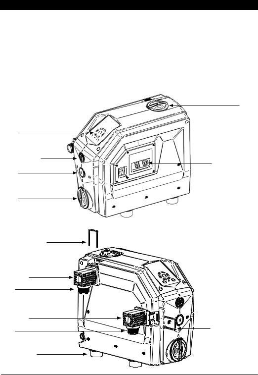
filling cap
inflation of the vessel
vent cap
drain cap
connector locking forks
Adjustable elbow fitting, with OR
delivery
Adjustable elbow fitting, with OR
suction
anti-vibration feet
cable glands I/O signals
 main switch
connector locking forks

Installation and hydraulic connections
1. Adjust the feet |
|
2. Remove the fork covers |
|
3. Remove the forks |
|
|
|||
|
|
|
|
|
|
|
|
|
|
4. Insert the elbow fittings with O-RING |
5. Insert the forks |
6. Insert the fork covers |
OUT
IN
 OK
OK
Electric connections (expansion board)
9-10 SLAVEE
Remove the cover |
|
7-8 0 V |
|
5-6 RS485 |
|
|
|
|
|
|
3-4 OUTPUT |
|
|
1-2 INPUT |
1-2 |
INPUT |
LEVEL SIGNAL - jumper in the absence of signal |
3-4 |
OUTPUT |
ALARM SIGNAL - max 0,3 A @ 230 Va.c. / 1A @ 30 Vd.c. |
5-6 |
RS 485 |
communication MASTER / SLAVE |
7-8 |
0 V |
not connected |
9-10 |
SLAVE |
if it is bridged, the inverter is SLAVEE |
 Loading...