

Page 1

Thank You!
Thank you from the entire PSE family for purchasing a PSE bow!
Your bow was manufactured from the finest materials available and
handcrafted with pride in the USA. With proper care you will enjoy the
use of this product for years to come.
Please read this entire booklet before shooting or adjusting your bow.
Remember, many adjustments to a compound bow require the use of a
bow press. Whenever shooting a bow, be certain of your target as well as
what else lies down range.
NOTE: IMPORTANT WARRANTY REGISTRATION INFORMATION IS ON PAGE 43
PSE COMPOUND BOW OWNER’S INFORMATION
Fill in the following information for your personal records.
Bow Model
Bow Serial Number:
See page 43 for the serial number location on your bow.
Purchased From:
Purchase Date:
Draw Length Draw Weight
PAGE
2
Page 2

COMPOUND BOW
USER’S GUIDE
INDEX
SUBJECT PAGE
Welcome to PSE and general product information ............................................................. 4
Compound bow terminology ................................................................................................ 5
PSE cable configurations ........................................................................................................ 6
PSE X-Tech™ bow press info ..............................................................................................7-9
Installation of accessories ....................................................................................................10
Other adjustments ............................................................................................................... 10
Setting up your bow ............................................................................................................. 11
FlexSlide™ installation and adjustments ............................................................................. 12
BackStop™ 3 installation and adjustments ......................................................................... 12
BackStop™ 2 installation and adjustments ......................................................................... 13
Sting Stop™ installation and adjustments ........................................................................... 13
Limb bands and cable guard dampers ............................................................................. 14
Changing the FlexSlide™ rod .............................................................................................. 15
PSE asymmetric idler ............................................................................................................ 15
Cam adjustments ................................................................................................................. 16
Draw stop information ......................................................................................................... 17
Limb stop adjustments ........................................................................................................ 17
PSE Pro Series bows- draw setting charts ........................................................................... 18
PSE Mainline bows- draw setting charts ............................................................................. 19
PSE Surge™with Morph™ cam settings charts ............................................................. 20-21
PSE Fever™One Pro with Morph™ cam settings charts ............................................... 22-23
PSE Stinger™ X with XS cam information ..................................................................... 24-25
PSE Vision™cam information...............................................................................................27
PSE Fever™ with Vision™ “performance” cam setting charts ...................................... 32-33
PSE Fever™ with Vision™ “grow with you” cam setting charts .................................... 34-35
PSE Mini Burner™ XT with Vision™ “performance” setting charts ............................... 36-37
PSE Mini Burner™ XT with Vision™ “grow with you” setting charts ............................ 38-39
PSE limited lifetime warranty information
PSE Signature items online store information ................................................................ 41
Notes ............................................................................................................................... 42
PSE warranty registration information............................................................................ 43
...................................................................... 40
PAGE
3
Page 3

COMPOUND BOW
USER’S GUIDE
GENERAL OPERATING INSTRUCTIONS
• Always inspect your bow thoroughly before each shooting session to insure that it is in good
working order. Check for worn, loose or missing components and have them replaced at an
authorized PSE dealer as required, i.e. bushings, spacers, etc.
•
Inspect your arrows to insure that they are straight, undamaged and that each nock is in good
condition. A cracked nock can break when fired from the bow and cause the bow to “dry fire”
resulting in possible injury to the archer and damage to the bow. Dry-firing is drawing and
releasing the bowstring without an arrow on the string.
•
When purchasing arrows for your bow, consult the selection chart from the arrow manufacturer
and select the correct arrow for your application. Always use an arrow that is at least 5 grains per
pound of peak bow weight. Failure to do so could cause personal injury and damage to your bow.
BOW MAINTENANCE
Your PSE bow will give you many years of use if maintained and cared for properly.
It is a mechanical device that is subject to wear and therefore must be inspected periodically and
given the proper adjustments and service. It is recommended that this service be performed at least
once a year by an authorized PSE dealer. All components, including string, cables, axles, e-clips,
limbs and riser should be carefully inspected for damage or wear.
STRINGS AND CABLES
Apply a light coat of high quality bowstring wax to your string and cable each time you shoot your
bow. It is especially important NOT to wax the area of the string that wraps around the idler wheel.
This area of the string should be treated with a cam lubricant. This will help reduce wear on your
string and cables. Inspect the string and cables regularly and replace them when there is evidence of
wear, every 5000 shots or every 12 months.
I
MPORTANT: Before servicing any PSE bow in a bow press, back out each limb
bolt the maximum number of turns from bottom.
• Keep synthetic cables and strings waxed. Apply bow string wax to your synthetic cables and string
before each shooting session.
•
Strings and cables must be replaced periodically. A worn cable or string can suddenly break
causing serious injury to the archer and damage to the bow. It is recommended that the string
and cables be replaced at least every 5,000 shots or 12 months.
PSE recommends that this work be performed by an authorized PSE dealer.
•
Always store your bow in a cool dry place. High temperatures, such as those that can occur in
the interior of a vehicle, can cause serious damage to your bow.
•
After use in high humidity or damp conditions, wipe metal components of your bow
with a light oil.
SAFETY
As with any weapon, safe operation of your PSE bow must always be the highest priority.
ALWAYS WEAR SAFETY GLASSES WHEN HANDLING A BOW.
Do not attempt to use your bow without proper instruction.
Doing so can result in serious injury.
a.
NEVER DRY-FIRE YOUR BOW. Dry-firing is drawing and releasing the bowstring without an
arrow on the string. Dry-firing will likely cause damage to the bow and serious injury to the
archer. In the event of a dry-fire, have an authorized PSE dealer inspect the bow
for damage.
Always be sure of your intended target as well as what lies behind the target area. An arrow can travel
b.
a considerable distance, so it is important to have a safe and sound backstop.
c.
If you draw a bow and need to let it down, do so in a slow and careful manner. Keep your
support arm straight and prepare for a rapid and violent let-down. Avoid hitting your hand on
protruding accessories such as the cable guard or quiver. Keep your head and face back and
out of danger during let-down. Never draw a bow with a peak weight above your comfort level.
Always use a wrist sling when drawing a bow.
d.
Never modify any part of the bow or its components by drilling extra holes or removing material.
This voids the warranty and presents safety problems.
e. It is not recommended to time the bow using a draw board unless the draw board is operated by
a winch or other mechanical pulling device.
PAGE
4
Page 4
TOP
LIMB
BOLT
QUIVER BRACKET
AND QUICK-MOUNT*
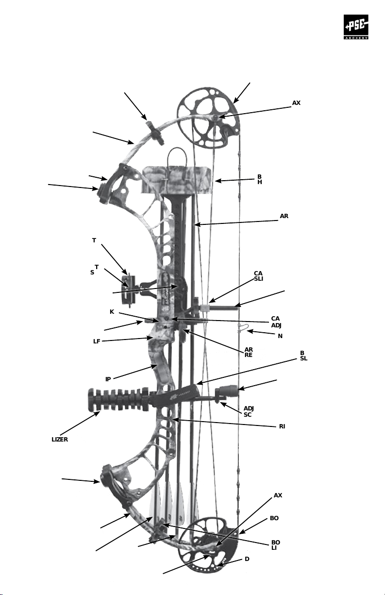
COMPOUND BOW
COMPOUND BOW TERMINOLOGY
(HYBRID DUAL CAM MODELS- SHOWN)
TOP CAM
or IDLER WHEEL
TOP
LIMB(S)
TOP LIMB
POCKET
SIGHT
SIGHT
PINS
TUNING
ALIGNMENT MARK
ARROW CLIP
ARROW SHELF
TOP
LIMB
BAND(S)
USER’S GUIDE
(SINGLE CAM MODEL)*
AXLE
BOW QUIVER
HOOD AND FOAM
ARROW
CABLE
SLIDE
ARROW
REST
CABLE GUARD ROD
OR FLEXSLIDE*
CABLE GUARD
ADJUSTMENT SCREW
NOCK LOOP
BOW
SLING
STABILIZER
BOTTOM
LIMB BOLT
BOTTOM
LIMBS
VANE
or
FLETCHING
GRIP
NOCK
MODULE
POSITION HOLES
BACKSTOP
BACKSTOP™2*
OR STINGSTOP
BACKSTOP™*
ADJUSTMENT
SCREW
RISER
AXLE
BOTTOM CAM
BOTTOM
LIMB BAND(S)
DRAW STOP
* = DEPENDS ON BOW MODEL
™
3* (SHOWN)
™
*
PAGE
5
Page 5
COMPOUND BOW
USER’S GUIDE
CABLE CONFIGURATIONS
IDLER WHEEL
ONE CAM BOW
BUSS CABLE
STRING
STRING
TOP CAM
TOP CAM
STRING
BUSS CABLE
CONTROL
CABLE
STRING
HYBRID CAM BOW
BUSS
CABLE
STRING
TWO CAM BOW
BOTTOM CAM
BOTTOM CAM
BUSS
CABLE
BUSS
CABLE
CONTROL
CABLE
BUSS
CABLE
STRING
STRING
PAGE
6
BUSS
CABLE
BUSS
CABLE
STRING
BOTTOM CAM
Page 6
COMPOUND BOW
USER’S GUIDE
PSE X TECHNOLOGY
PSE X Technology bows come with many unique features that will enhance your
archery experience.
USING A BOW PRESS WITH X TECHNOLOGY BOWS
ALL PSE X Technology bows MUST be serviced in an approved bow press and require special
consideration. Do not attempt to service these bows in any bow press without reviewing the
procedures described herein.
Use of a non-approved bow press or improper use of an approved bow press WILL result
in damage to the bow and possible personal injury. Damages incurred by improper use
or maintenance will not be covered under the warranty. See the PSE website at
www.pse-archery.com for a list of approved bow presses.
There are two basic types of approved presses available: compression-type
and pull-type. (Pg8)
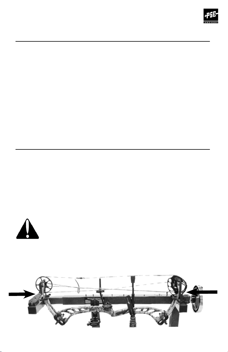
COMPRESSION-TYPE BOW PRESS: (PREFERRED)
This type of press pushes in a horizontal direction against the tips of the limbs.
No other support for the bow is required.
When using a press of this type, back each limb bolt out the maximum number of turns
indicated on your bow’s hang tag. Position the bow in the press and crank press inward to
apply a compression force against the limb tips as shown below.
COMPRESS ONLY FAR ENOUGH TO LOOSEN THE STRING AND CABLES.
OVER COMPRESSING COULD BREAK THE LIMBS AND CAUSE PERSONAL
INJURY.
ANY DAMAGES INCURRED FROM OVER-COMPRESSING WILL NOT BE
COVERED UNDER WARRANTY.
COMPRESSION-TYPE BOW PRESS
X Technology continued on next page
PAGE
7
Page 7
COMPOUND BOW
USER’S GUIDE
PSE X TECHNOLOGY USING A BOW PRESS
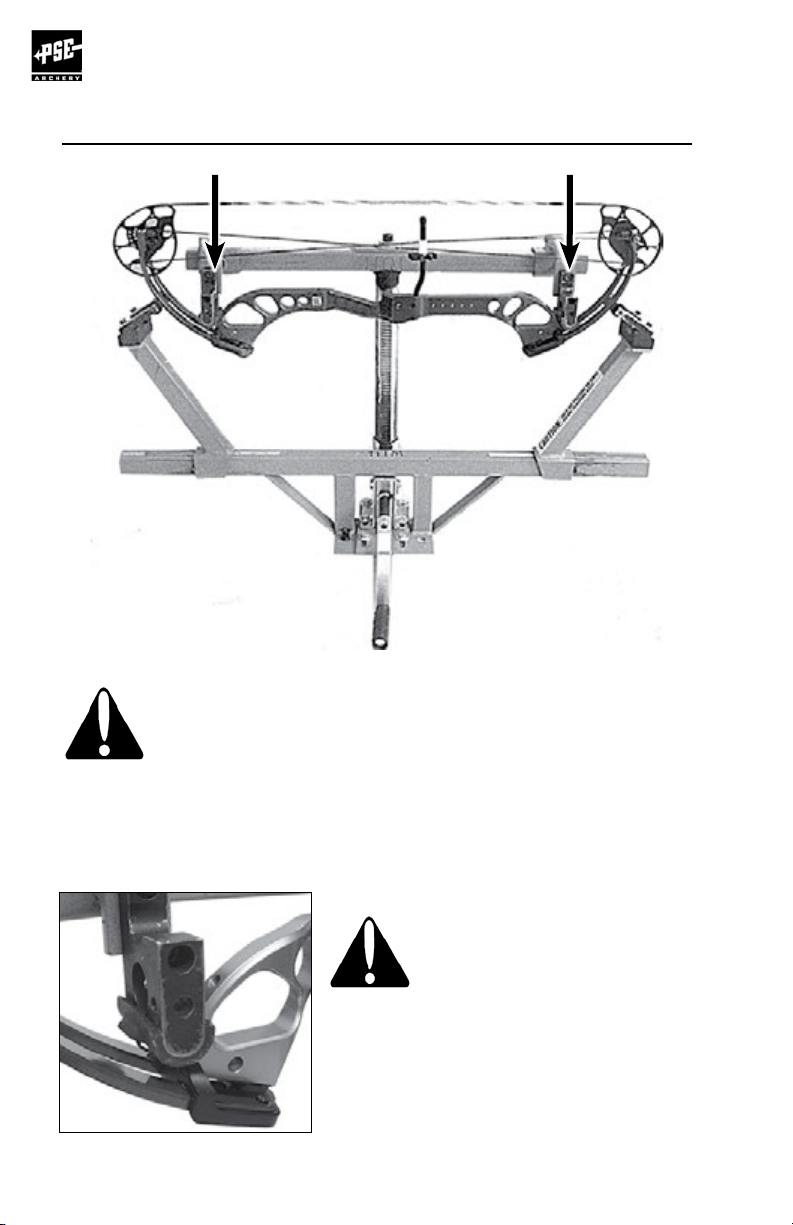
PULL-TYPE BOW PRESS
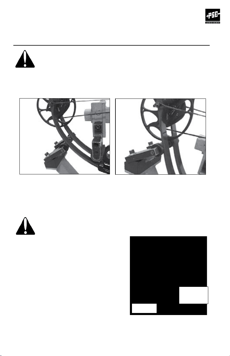
PULL-TYPE BOW PRESS:
This type of press pulls the riser of the bow in a vertical direction between
rollers that compress the limbs.
When using this type press it is very important to position the rollers and
pressure points correctly! See illustration above.
Back each limb bolt out the maximum number of turns indicated on your bow’s hang tag
and position the pressure points on the riser as close to the limbs as possible WITHOUT
making contact with the limbs as shown in the photo below.
THE PRESSURE POINTS MUST NOT CONTACT THE
LIMBS AT ANY TIME DURING SERVICING.
PULL-TYPE BOW PRESS
PAGE
8
X Technology continued on next page
Page 8
COMPOUND BOW
USER’S GUIDE
PSE X TECHNOLOGY USING A BOW PRESS (Continued)
Position the limb rollers outward on the limbs so that when the riser is pulled down
the bow does not slip through/between the rollers before releasing tension on the
string and cables. The rollers must be at least 4” from the limb pockets or the limbs
will break. While placing tension on the limbs, BE VERY CAREFUL NOT TO PULL THE RISER
DOWN TOO FAR. DEFLECT THE LIMBS JUST ENOUGH TO REMOVE THE STRING AND
CABLES. Never allow the rollers to go past the end of the limb belly (thinnest part).
Service such as peep and string mounted vibration damper installation and string replacement
can be performed with a “Pocket Press” portable bow press available from your local PSE
dealer. These pocket presses are available for a variety of axle-to-axle lengths and cam types.
SERVICING BOWS WITH PSE FT CAMS (PSE FULL THROTTLE™)
CAUTION • CAUTION • CAUTION!
When servicing bows with PSE FT cams, such as the
Full Throttle™, it is important to use a bow press
that has enough clearance for the cams.
On some bow presses the cams may make
contact with the area shown in Figure 1 when
compressing the limbs. Watch very carefully as the
bow is compressed. If either cam comes in contact
with the bow press, STOP IMMEDIATELY
or permanent damage to bow
components may occur.
Contact the bow press manufacturer for
further information.
Figure 1
Cam may
hit here
PAGE
9
Page 9
COMPOUND BOW
USER’S GUIDE
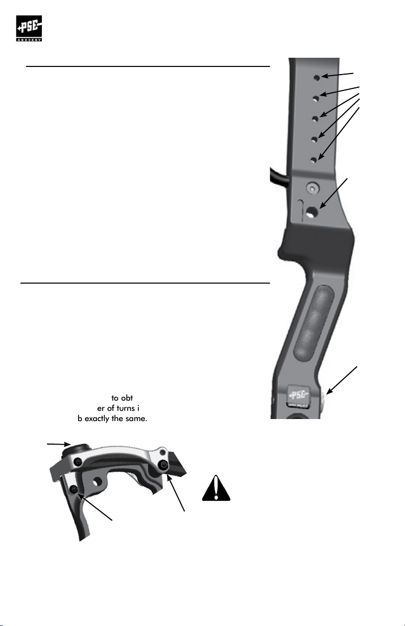
INSTALLATION OF ACCESSORIES
Arrowrest/Overdraw: The arrowrest or overdraw should be
installed according to the instructions received with the product.
It is usually mounted to the riser in the threaded hole on the
side opposite the shelf (Hole “A”) using the hardware provided
with the arrowrest or overdraw.
Sight: The sight should be installed according to the instructions
received with the product. It is usually mounted to the riser in
the threaded holes (Holes “B”) on the side opposite the shelf
using the hardware provided with the sight. Some bows are
equipped with multiple sight mounting holes which allow the
sight to be moved up or down.
Stabilizer: The stabilizer should be mounted according to the
manufacturer’s recommendation. It is usually mounted in the
threaded hole on the front of the riser (Hole “C”).
Bow Sling: The bow sling attaches to the riser of the bow
generally with the stabilizer. If a stabilizer is not used, attach the
sling to the riser with the correct sized bolt (5/16” - 24) using
the hole provided for the stabilizer (Hole “C”).
OTHER ADJUSTMENTS
Draw Weight: Your bow is factory-set to within 2 lbs.
of the peak draw weight indicated on the bow hang tag and the
last 2 digits of the serial number. Changes in draw weight can
be made by turning the limb bolt in or out. Before making any
changes in weight, turn the limb bolt clockwise to the bottom
position. Never use extreme torque when turning the bolt or
damage to the limb may occur. The limb bolt may then be
turned counterclockwise to obtain the desired weight, but NEVER
more than the number of turns indicated on the hang tag.
Adjust each limb exactly the same. (See note and Fig. A below)
Limb
bolt
Holes
B
Hole
A
Hole
C
CAUTION: On some bow models,
the limb bolt locking screw, limb
Fig. A
Limb
Pocket tang
locking screw
Your Authorized PSE Dealer is supplied with technical information on PSE bows
and cams. Please see your Dealer for assistance when making these adjustments.
PAGE
10
support
screw
support screws or pocket tang
locking screw MUST be loosened
BEFORE adjusting.
Page 10
COMPOUND BOW
SETTING-UP YOUR BOW
Tuning
NOCKING POINT PLACEMENT:
Finger shooters: Install the nocking point so that the arrow
passes the center of the arrow rest mounting hole and
runs slightly point-down relative to the tuning mark on the
window of the bow.
Release Aid shooters: Install the nocking point so that
the arrow passes the center of the arrow rest mounting
hole and runs parallel to the alignment mark on the
window of the bow.
ARROW REST ADJUSTMENT:
When shooting with a release aid, the in/out position
of the arrow rest should be adjusted so that the arrow
runs parallel with the tuning mark on the shelf when
viewed from above. When shooting with fingers the
arrow should point slightly outside the tuning alignment
mark on the shelf.
NOTE: Tuning alignment marks are for reference
only. Adjustments will likely be necessary to
nocking point and in/out position during tuning
Mark
USER’S GUIDE
Arrow rest mounting hole
Tuning
Mark
Alignment
Mark
SIGHT ADJUSTMENT:
When adjusting the sight pin locations, always remember
to “follow the group”. That is, if the shot group is to the
left of the target, move the sight pins to the left. If the shot
group is low, move the sight pins down.
••
•
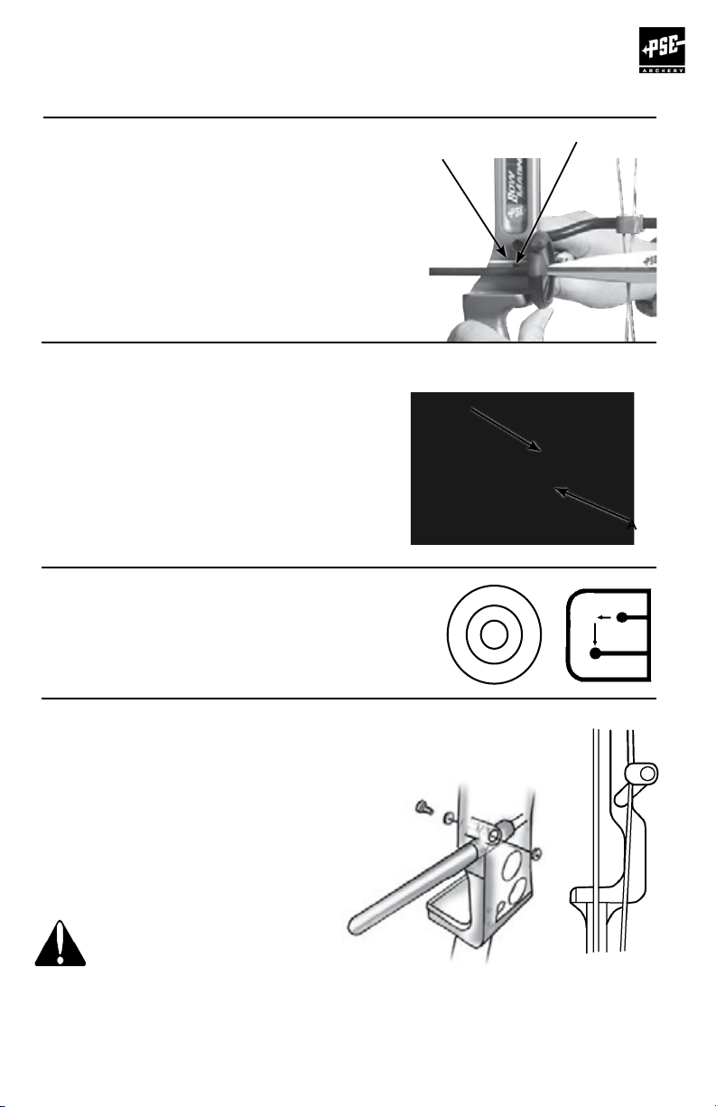
CABLE GUARD ADJUSTMENT
AND INSTALLATION:
Install the cable guard as shown in
Figure A. Adjust the cable guard so the
cables just clear the arrow vanes. On bows
using an offset cable guard rod, adjustments
must be done with the rod in the up position
(approximately 2 o’clock) as shown in
Figure B (10 o’clock for left handed bows).
Over-rotating an adjustable cable
guard creates excessive arrow
clearance and may cause the cable
to track incorrectly on the wheels
and cause personal injury and/or
damage to the bow.
Note: Rotational adjustments to the cable guard may affect arrow tuning
Figure A
Figure B
PAGE
11
Page 11
COMPOUND BOW
USER’S GUIDE
FLEXSLIDE™ ADJUSTMENT & INSTALLATION
The PSE FlexSlide™ cable guard system is based on the same advanced
design and analysis used to create PSE Limbs. The flex-tuned design
and adjustable offset are engineered to create more consistent lateral
loads through the draw cycle and improve bow accuracy.
1. The standard factory setting adjusts the
FlexSlide
arrow clearance.
2. To adjust the lateral position, turn the
adjustment screw counterclockwise to
reduce arrow clearance or clockwise to
increase arrow clearance.
3. After making adjustments to your
FlexSlide
and BackStop
the bow, the buss cable should never
contact the arrow shaft or any part of
the Backstop
4. If any contact exists, tighten the
adjustment screw to create adequate
clearance. One full turn on the adjustment
screw will move the slide approximately 1/8”.
™
to its bottom position for maximum
™
, check both arrow clearance
™
clearance. When drawing
™
.
FlexSlide
Pivot with
Alignment
Tabs
Low Friction
FlexSlide Rod
FlexSlide
Limb
FlexSlide
Washer with
Alignment Tabs
Lateral
Adjustment
Screw
NOTE: Lateral adjustments to the FlexSlide
™
may affect arrow tuning.
BACKSTOP™3 INSTRUCTIONS
Note: Some PSE Pro Series and Mainline bow models come from the factory with the Backstop
3 installed. These instructions refer to reinstallation or adjustment if needed after making
adjustments
1. Install the BackStop™ 3 into the threaded hole below the
grip on the string-facing side of the bow.
2. Adjust the rotator until it makes contact with the string. Mark the string ¼”
above and ¼” below where it makes contact with the string. Remove the Backstop™ 3
and add serving to that area of the string if it does not already exist. Reinstall the
Backstop™ 3.
3. Securely tighten the base to the bow handle using the cross-drilled hole.
4. Adjust the Backstop™3 by rotating and sliding in and out to the desired position.
Tighten the rotator screw. The Backstop™ 3 design allows for the
bumper to be positioned so the string strikes the center of the bumper.
It is desired to have some clearance (approximately 1/16”) between the bumper
and the bowstring at brace.
Lateral Adjustments
Serve string
in this area.
1/16”
™
PAGE
12
Rotational Adjustments
Page 12
COMPOUND BOW
USER’S GUIDE
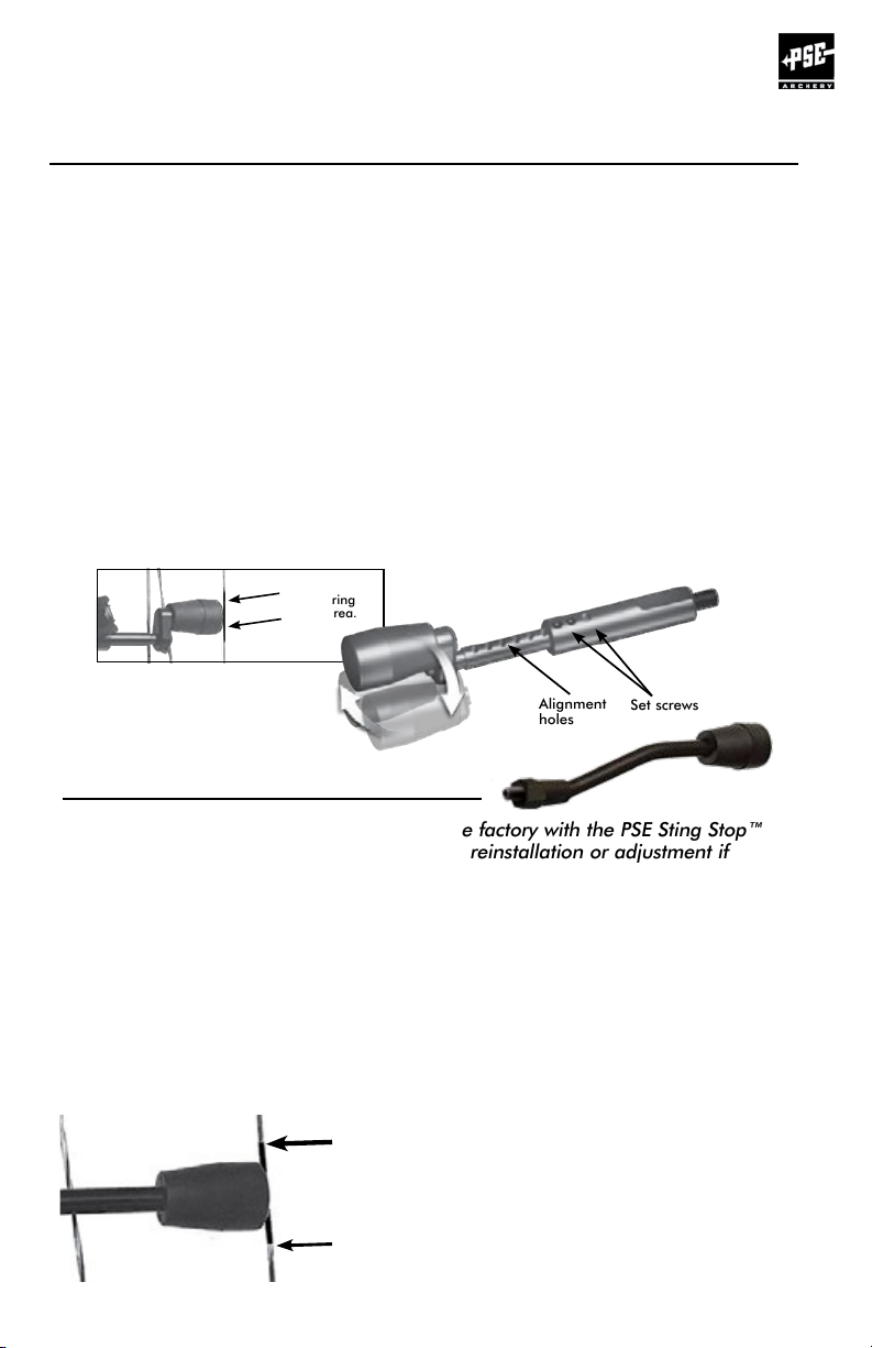
BACKSTOP™2 INSTRUCTIONS
Note: Some PSE bow models come from the factory with the Backstop™ 2 installed. These
instructions refer to reinstallation or adjustment if needed after making adjustments.
to your PSE bow.
1. Remove the set screws from the base using a T8 Torx wrench.
2. Install the Backstop™ 2 into the threaded hole below the
grip on the string-facing side of the bow.
3. Extend the Backstop™ 2 until it makes contact with the string. Mark the string ¼”
above and ¼” below where it makes contact with the string. Remove the Backstop™ 2
and add serving to that area of the string. Reinstall the Backstop™ 2.
4. Securely tighten the base to the bow handle.
6. Extend rod from base. Install the set screws to secure rod in this position.
Tighten set screws. It is desired to have some clearance (approximately 1/16”)
between the bumper and the bowstring at brace.
7. Rotation instructions- Adjust the Backstop™ 2 to the desired position and tighten the
rotator screw. The Backstop™ 2 design allows for the bumper to be positioned so the
string strikes the center of the bumper. It is desired to have some clearance
(approximately 1/16”) between the bumper and the bowstring at brace.
Serve string
in this area.
Alignment
holes
Set screws
STING STOP™ INSTRUCTIONS
Note: Several PSE bow models come from the factory with the PSE Sting Stop™
Backstop installed. These instructions refer to reinstallation or adjustment if
needed after making adjustments to your PSE bow.
1. Thread the Sting Stop™nut all the way up toward the bumper of the Sting Stop™ rod.
2. Thread the Sting Stop™rod into the threaded hole below the grip on the riser. The
bowstring will need to be displaced slightly to one side to thread the rod into the bow.
3. Unscrew the Sting Stop™until the rubber bumper approaches the bowstring. Mark the
string 1/4” above the rubber bumper in its highest position and 1/4” below the bumper
in its lowest position. Remove the Sting Stop™ and add serving to the marked area of the
string if it does not already exist. Reinstall the Sting Stop™.
4. Adjust the Sting Stop™to the desired position and
tighten the Sting Stop™ nut against the riser. The
Sting Stop™ design allows for the bumper to be
positioned so the string strikes the center of the
Serve string
in this area.
bumper. It is desired to have some clearance
(approximately 1/16”) between the bumper and the
bowstring at brace. It is preferred to have the Sting
Stop™rod in the up position if possible, but may
not be possible in order to achieve the necessary
clearance and contact point.
PAGE
13
Page 13
COMPOUND BOW
USER’S GUIDE
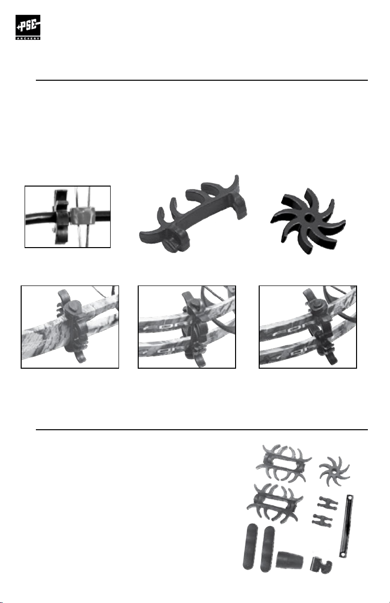
INSTALLING LIMB BANDS AND CABLE GUARD DAMPER
If your bow is equipped with a Cable Guard Damper it should be even with
the cable slide when the bow is at rest. More than one Cable Guard Damper
can be used.
If your solid limb bow is equipped with limb bands, the proper placement of the
bands is approximately 1/8” beyond the limb fork.
If your split limb bow is equipped with limb bands, the proper placement of the
bands is at least 1/4” away from the cam.
Cable Guard Damper
Limb Band on
Solid Limb
Limb Band Damper Cable Guard Damper
Limb Bands across
Split Limb
Limb Bands on
Split Limb (one per limb)
CHECK OUT OUR LINE OF BRIGHT COLORED RUBBER
Your PSE dealer carries a full line of colored rubber
add-ons for your PSE bow. Choose from pink,
orange, yellow, blue, purple, black, red and
lime green.
PAGE
14
Page 14

COMPOUND BOW
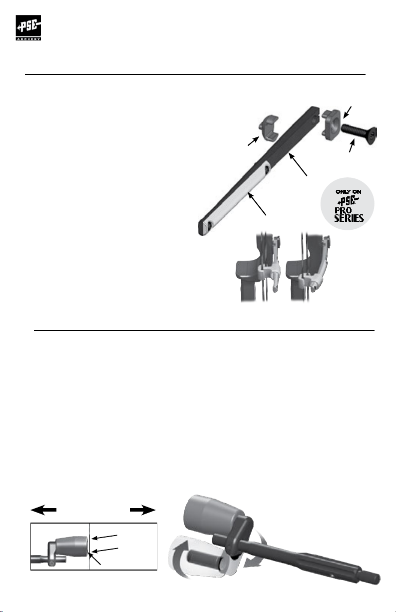
CHANGING THE FLEX SLIDE ROD
If you are replacing a PSE Flex slide rod or changing
to a different color, follow these instructions.
FIGURE 1:
Unsnap the two strings from the cable slide- noting
the orientation of the two different clips (shorter clip
closest to the riser)
FIGURE 2:
Slide the cable slide off the Flex slide
FIGURE 3:
Using a T9 torx wrench remove the two screws.
Replace with the new Flex slide rod and tighten
the screws.
Re-assembly is the reverse of the
instructions above.
USER’S GUIDE
PSE ASYMMETRIC IDLER
PSE single cam bows are equipped with a special
asymmetric idler wheel, which is assembled on the
top limbs. It is essential that the idler be
oriented properly.
The wide edge of the idler always goes to the
cable guard side of the bow.
The illustration shows the proper orientation of
the idler for a right-handed bow when viewed while
holding the bow as it is shot.
Wide edge
PAGE
15
Page 15

COMPOUND BOW
USER’S GUIDE
CAM ADJUSTMENTS
WHEELS/CAMS: Many PSE wheels and cams have adjustable features. Each one comes from
the factory set up and ready to use but there may be occasions that you need to adjust the
characteristics of your bow. In some cases you will need a PSE Tune Chart to determine what
to adjust, and you may need to see a PSE Dealer for information. If you are not sure of the
adjustment you are making, stop and see your PSE Dealer for assistance. In some cases, an
appropriate bow press will be needed to make adjustments to cams and wheels. If you do not
have an appropriate press, see your PSE Dealer.
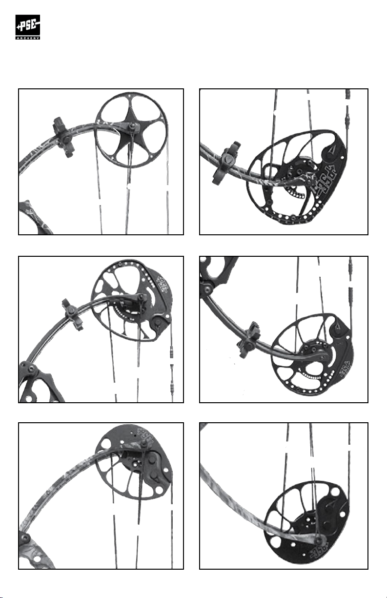
CAM ORIENTATION:
On cams with orientation marks, a reference mark is found to indicate an approximate
orientation. This line is for reference only is meant to give approximate orientation
only and may vary between bow models. The orientation of the cams may be changed slightly
by twisting or untwisting the string or cables.
ALL INNER-CAMS:
The inner-cam system allows draw length adjustments over a prescribed range usually without
putting the bow in a bow press. There are two types of inner-cam systems: discrete setting
inner-cams and Posi-Lock inner-cams.
Discrete setting inner-cams have the adjustment screws going through a specific hole in the
inner-cam and threading into the cam. The screws need to be completely removed to make
adjustments. The “A” setting is the longest draw length for that bow and draw lengths get
shorter as you progress through the alphabet (A to B, B to C, etc.)
Posi-lock adjustable inner-cams are adjustable in ½” draw length increments. The “A” setting is
the longest setting for the cam. Draw lengths get shorter as you progress through the alphabet
(“A” to “B”, “B” to “C”, etc.) by roughly ½” per letter.
Second and third generation Posi-lock inner-cams
allow for draw length adjustments in ½” increments
without changing inner-cams. To adjust draw length,
loosen the two 8-32 button head screws two full
turns. This will allow the inner-cam to be lifted far
enough to disengage the positioning pin and allow
the inner-cam to rotate to a new position. Some
cams may require the 8-32 button head screws to
move to alternate locations to reach the new draw
length adjustment position. Some draw length
adjustment positions may not be accessible without
putting the bow in a bow press. When the new
draw length adjustment position has been achieved
with the inner-cam, tighten the two 8-32 button
head screws and move the draw stop to the
matching setting (“A” and “A”, “B” and “B”).
In cases where there is an inner-cam on both the top and bottom cam, both cams must be
set in the same letter position for the bow to tune and shoot properly. In cases where there
is a separate draw stop, the draw stop must be moved to the hole marked with the letter
corresponding to the inner-cam setting.
PAGE
16
8-32 Button Head Screw
Positioning Pin
Page 16
COMPOUND BOW
USER’S GUIDE
INFORMATION ON DRAW STOP ADJUSTMENTS:
The position of the draw stop must match the setting on the inner-cam. For example, if the cam is set on “E”, the draw
stop must be placed in one of the draw stop holes marked with an “E”. If the inner-cam is in the “B” setting, the stop
must be in the “B” position. Certain hybrid cams have top and bottom stops. They can be shot with both stops for a
harder “wall” or with only the top stop for a softer “wall”. Never shoot hybrid cams with the two stop option with only the
bottom stop. In either case, the stops need to be in the holes marked with the same marking as the inner-cam setting.
Draw Stop
Draw Stop
Screw
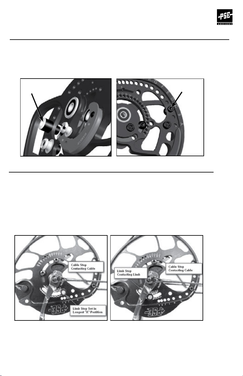
LIMB STOP ADJUSTMENTS
On bows equipped with a limb stop and cable stop, use of the limb stop is optional. If
choosing not to use the limb stop it may be removed or set in the longest “A” position so
that it does not contact the limb before the cable stop. Engraving for limb stop positions is
approximate and for reference only. Many factors will cause changes to the optimum limb
stop position.
OPTION 1: (If a safe method of holding the bow at full draw is available, such as a draw
board) Set Limb Stop to the Longest “A” Location and time bow to cable stops at desired
draw length as shown in Figure 1. Using a safe method to hold the bow at full draw adjust
limb stop so it contacts the limb as shown in Figure 2.
FIGURE 2FIGURE 1
OPTION 2: Set Limb Stop to the Longest “A” Postition. Time bow to cable stops at desired
draw length.Set Limb stop to the corresponding stop position. Draw bow with an arrow,
pointed at a safe range or target and observe whether the cable stop or Limb Stop contacts
first. Make small adjustments to the Limb Stop position and recheck until it contacts at
the same time as the cable stop.
PAGE
17
Page 17
COMPOUND BOW
USER’S GUIDE
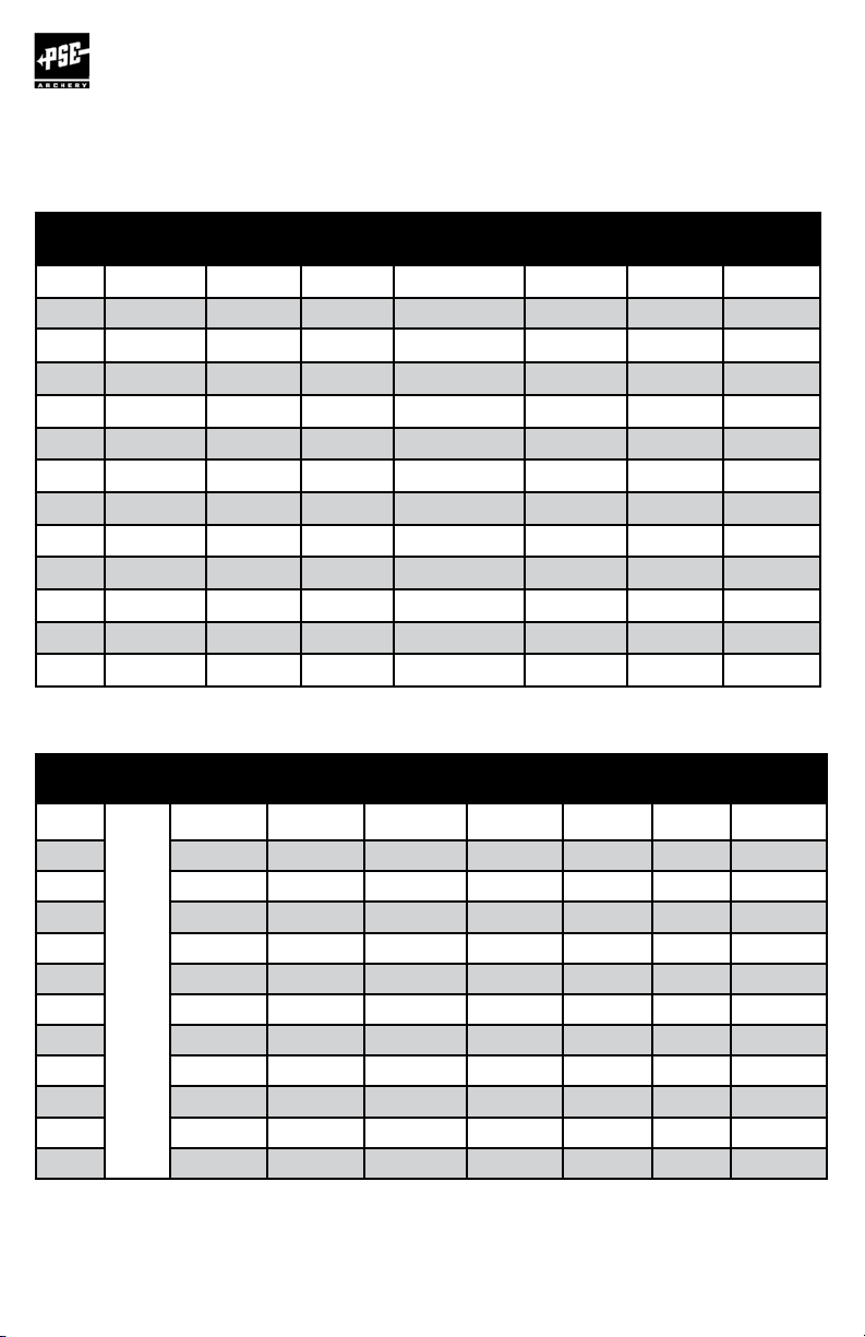
PSE PRO SERIES BOWS: DRAW SETTING CHART
NOTE: The PSE Full Throttle has cam-specific draw lengths from 26-1/2” to 30” in 1/2” increments.
SETTING DECREE DNA SP SOURCE HD PREMONITION HD
A 30 30 31 1/2 30 30 33 31
B 29 1/2 29 1/2 31 29 1/2 29 1/2 32 1/2 30 1/2
C 29 29 30 1/2 29 29 32 30
D 28 1/2 28 1/2 30 28 1/2 28 1/2 31 1/2 29 1/2
E 28 28 29 1/2 28 28 31 29
F 27 1/2 27 1/2 29 27 1/2 27 1/2 30 1/2 28 1/2
G 27 27 28 1/2 27 27 30 28
H 26 1/2 26 1/2 28 26 1/2 26 1/2 29 1/2 27 1/2
I 26 26 27 1/2 26 26 29 27
J 25 1/2 25 1/2 27 25 1/2 25 1/2 28 1/2 26 1/2
K 25 25 26 1/2 25 25 28 26
L 24 1/2 24 1/2 26 24 1/2 24 1/2 27 1/2 25 1/2
M
- -
25 1/2 24 24 - -
VERGE
& STILETTO
FREAK SP DRIVE LT
SETTING
FEVER
PRO
B 31
C 30 1/2
D 30
E 29 1/2
SEE
F 29
PAGES
24-25
G 28 1/2
H 28
I 27 1/2
J 27
K -
L -
PAGE
18
DOMINATOR
MAX
31 1/2
DOMINATOR
MAX MD
30 30 1/2 33
29 1/2 30 32 1/2
29 29 1/2 32
28 1/2 29 31 1/2
28 28 1/2 31
27 1/2 28 30 1/2
27 27 1/2 30
26 1/2 27 29 1/2
26 26 1/2 29
25 1/2 26 28 1/2
25
24 1/2
DOMINATOR
3D MAX
-
-
DOMINATOR
3D MAX DC
28
27 1/2
SUPRA
MAX
PHENOM
PHENOM
SD
30 30 28 1/2
29 1/2 29 1/2 28
29 29 27 1/2
28 1/2 28 1/2 27
28 28 26 1/2
27 1/2 27 1/2 26
27 27 25 1/2
26 1/2 26 1/2 25
26 26 24 1/2
25 1/2 25 1/2 24
- - 23 1/2
- - 23
Page 18

COMPOUND BOW
USER’S GUIDE
PSE MAIN LINE BOWS: DRAW SETTING CHART
SETTING BOWMADNESS 34 BOWMADNESS 32 BOWMADNESS 30
A 30 1/2 30 30
B 30 29 1/2 29 1/2
C 29 1/2 29 29
D 29 28 1/2 28 1/2
E 28 1/2 28 28
F 28 27 1/2 27 1/2
G 27 1/2 27 27
H 27 26 1/2 26 1/2
I 26 1/2 26 26
J 26 25 1/2 25 1/2
K 25 1/2 25 25
L 25 24 1/2 24 1/2
M 24 1/2 24 24
N - - 23 1/2
PSE Mainline bows with highly adjustable cams continued on page 20
PAGE
19
Page 19

COMPOUND BOW
USER’S GUIDE
PSE HIGHLY ADJUSTABLE
CAM INFORMATION
The following pages of information apply to the
following PSE models:
™
• PSE SURGE
™
• PSE FEVER
• PSE STINGER
• PSE FEVER
ONE PRO
™
X
™
• PSE MINI BURNER
PAGE
20
™
XT
Page 20

COMPOUND BOW
USER’S GUIDE
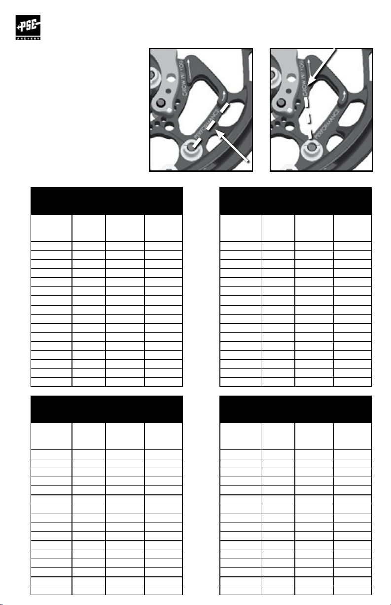
PSE MORPH™ CAM INFORMATION
BOWS: PSE SURGE
ADJUSTING THE MORPH CAM:
Select the “PERFORMANCE” or “GROW WITH YOU” cable position based on the desired draw
characteristics and peak weight range.
Rotate the inner-cam position (A thru Q) to match the desired draw length. To adjust, loosen
each #8-32 button head screw approx. 2 full turns. Rotate into position and tighten screws.
NOTE: the 3rd tapped hole position in the inner-cam may be used if the screw becomes hidden
behind the limb.
The “R” position is a unique guide and hub track design for minimum draw weight
and draw length. Remove the inner-cam and stop from the cam, align with the “R”
holes and install the screws.
AND FEVER
™
ONE PRO
™
PAGE
21
Page 21

COMPOUND BOW
USER’S GUIDE
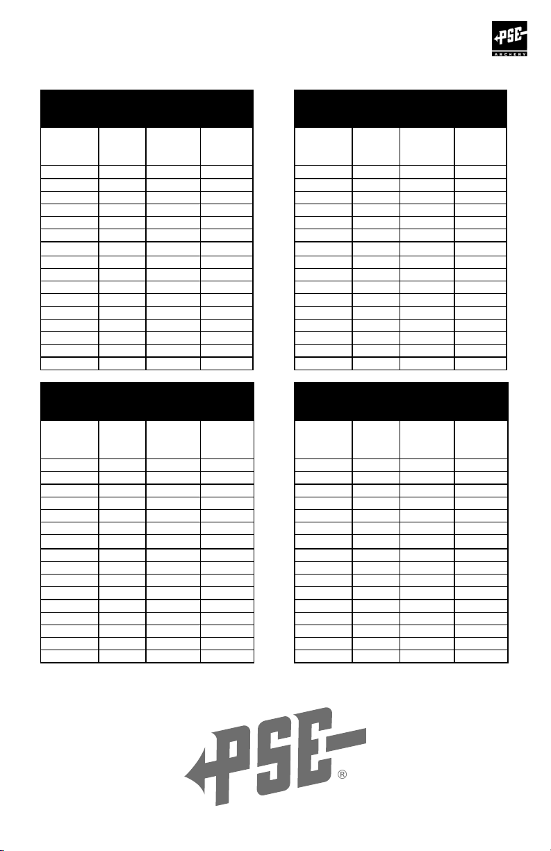
PSE SURGE™ AND FEVER™ONE PRO:
MORPH™ CAM DRAW SETTING CHARTS
PSE SURGE 70#
PERFORMANCE
CABLE SETTINGS
Inner
Cam
Stop
Setting
A 30” 70 49
B 29½” 70 49
C 29” 70 49
D 28½” 70 49
E 28” 70 49
F 27½” 70 49
G 27” 70 49
H 26½” 70 49
I 26” 70 49
J 25½” 70 49
K 25” 70 49
L 24½” 70 49
M 24” 70 49
N 23½” 70 49
O 23” 70 49
P 22½” 70 49
Q 22” 70 49
R* N/A N/A N/A
Draw
Length
Setting
Draw
Weight
at
Bottom
Draw
Weight
12 Turns
Off
PSE SURGE 70#
GROW WITH YOU
CABLE SETTINGS
Inner
Cam
Stop
Setting
A 29½” 62½ 43¾
B 29” 61¾ 43½
C 28½” 61¼ 43¼
D 28” 60¾ 42½
E 27½” 60 42
F 27” 59½ 41½
G 26½” 59 40¾
H 26” 58¼ 40¼
I 25½” 57¾ 39¾
J 24⅞” 57 39
K 24¼” 56 38½
L 23⅝” 54¾ 37¾
M 23” 53½ 36½
N 22⅜” 51¼ 35
O 21¾” 48¾ 33½
P 21⅛” 45¾ 31¾
Q 20½” 42½ 30
R 19½” 32¾ N23A
Draw
Length
Setting
Draw
Weight
at
Bottom
Draw
Weight
12 Turns
Off
*CAUTION: The “R” inner-cam and stop settings may ONLY
be used with the cable in the “GROW WITH YOU” position.
PAGE
22
Page 22

COMPOUND BOW
USER’S GUIDE
PSE SURGE 60#
PERFORMANCE
CABLE SETTINGS
Inner
Cam
Stop
Setting
Draw
Length
Setting
A 30” 60 42
B 29½” 60 42
C 29” 60 42
D 28½” 60 42
E 28” 60 42
F 27½” 60 42
G 27” 60 42
H 26½” 60 42
I 26” 60 42
J 25½” 60 42
K 25” 60 42
L 24½” 60 42
M 24” 60 42
N 23½” 60 42
O 23” 60 42
P 22½” 60 42
Q 22” 60 42
R* N/A N/A N/A
Draw
Weight
at
Bottom
PSE SURGE 50#
PERFORMANCE
CABLE SETTINGS
Inner
Cam
Stop
Setting
Draw
Length
Setting
A 30” 50 35
B 29½” 50 35
C 29” 50 35
D 28½” 50 35
E 28” 50 35
F 27½” 50 35
G 27” 50 35
H 26½” 50 35
I 26” 50 35
J 25½” 50 35
K 25” 50 35
L 24½” 50 35
M 24” 50 35
N 23½” 50 35
O 23” 50 35
P 22½” 50 35
Q 22” 50 35
R* N/A N/A N/A
Draw
Weight
at
Bottom
Draw
Weight
12 Turns
Off
Draw
Weight
12 Turns
Off
PSE SURGE 60#
GROW WITH YOU
CABLE SETTINGS
Inner
Cam
Stop
Setting
Draw
Length
Setting
A 29½” 53½ 37½
B 29” 53 37¼
C 28½” 52½ 37
D 28” 52 36½
E 27½” 51½ 36
F 27” 51 35½
G 26½” 50½ 35
H 26” 50 34½
I 25½” 49½ 34
J 24⅞” 48¾ 33½
K 24¼” 48 33
L 23⅝” 47 32¼
M 23” 45¾ 31¼
N 22⅜” 44 30
O 21¾” 41¾ 28¾
P 21⅛” 39¼ 27¼
Q 20½” 36½ 25¾
R 19½” 28 20
Draw
Weight
at
Bottom
PSE SURGE 50#
GROW WITH YOU
CABLE SETTINGS
Inner
Cam
Stop
Setting
Draw
Length
Setting
A 29½” 44¾ 31
B 29” 44½ 30¾
C 28½” 44¼ 30½
D 28” 44 30¼
E 27½” 43½ 30
F 27” 43 29¾
G 26½” 42½ 29¼
H 26” 42 28¾
I 25½” 41½ 28¼
J 24⅞” 40¾ 27¾
K 24¼” 39¾ 27¼
L 23⅝” 38¾ 26½
M 23” 37¾ 25¾
N 22⅜” 36½ 24¾
O 21¾” 35 23¾
P 21⅛” 33½ 22¾
Q 20½” 31½ 21½
R 19½” 23½ 16½
Draw
Weight
at
Bottom
Draw
Weight
12 Turns
Off
Draw
Weight
12 Turns
Off
PAGE
23
Page 23

COMPOUND BOW
USER’S GUIDE
PSE FEVER™ ONE PRO:
MORPH™ CAM DRAW SETTING CHARTS
PSE FEVER ONE PRO 70#
PERFORMANCE
CABLE SETTINGS
Inner
Cam
Stop
Setting
Draw
Length
Setting
A 30” 70 49
B 29½” 70 49
C 29” 70 49
D 28½” 70 49
E 28” 70 49
F 27½” 70 49
G 27” 70 49
H 26½” 70 49
I 26” 70 49
J 25½” 70 49
K 25” 70 49
L 24½” 70 49
M 24” 70 49
N 23½” 70 49
O 23” 70 49
P 22½” 70 49
Q 22” 70 49
R* N/A N/A N/A
Draw
Weight
at
Bottom
Draw
Weight
12 Turns
Off
PSE FEVER ONE PRO 70#
Inner
Cam
Stop
Setting
A 29½” 62½ 43¾
B 29” 61¾ 43½
C 28½” 61¼ 43¼
D 28” 60¾ 42½
E 27½” 60 42
F 27” 59½ 41½
G 26½” 59 40¾
H 26” 58¼ 40¼
I 25½” 57¾ 39¾
J 24⅞” 57 39
K 24¼” 56 38½
L 23⅝” 54¾ 37¾
M 23” 53½ 36½
N 22⅜” 51¼ 35
O 21¾” 48¾ 33½
P 21⅛” 45¾ 31¾
Q 20½” 42½ 30
R 19½” 32¾ N23A
GROW WITH YOU
CABLE SETTINGS
Draw
Length
Setting
Draw
Weight
Bottom
Draw
at
Weight
12 Turns
Off
PSE FEVER ONE PRO 60#
PERFORMANCE
CABLE SETTINGS
Inner
Cam
Stop
Setting
A 29” 60 42
B 28½” 60 42
C 28” 60 42
D 27½” 60 42
E 27” 60 42
F 26½” 60 42
G 26” 60 42
H 25½” 60 42
I 25” 60 42
J 24½” 60 42
K 24” 60 42
L 23½” 60 42
M 23” 60 42
N 22½” 60 42
O 22” 60 42
P 21½” 60 42
Q 21” 60 42
R* N/A N/A N/A
Draw
Length
Setting
Weight
Bottom
*CAUTION: The “R” inner-cam and stop settings may ONLY
PAGE
24
be used with the cable in the “GROW WITH YOU” position.
Draw
at
Draw
Weight
12 Turns
Off
PSE FEVER ONE PRO 60#
GROW WITH YOU
CABLE SETTINGS
Inner
Cam
Stop
Setting
A 28½” 53½ 37½
B 28” 53 37¼
C 27½” 52½ 37
D 27” 52 36½
E 26½” 51½ 36
F 26” 51 35½
G 25½” 50½ 35
H 25” 50 34½
J 24” 48¾ 33½
K 23½” 48 33
L 22⅞” 47 32¼
M 22¼” 45¾ 31¼
N 21⅝” 44 30
O 21” 41¾ 28¾
P 20¼” 39¼ 27¼
Q 19½” 36½ 25¾
R 18½” 28 20
Draw
Length
Setting
I 24½” 49½ 34
Draw
Weight
at
Bottom
Draw
Weight
12 Turns
Off
Page 24

COMPOUND BOW
USER’S GUIDE
PSE FEVER ONE PRO 50#
PERFORMANCE
CABLE SETTINGS
Inner
Cam
Stop
Setting
Draw
Length
Setting
A 29” 50 35
B 28½” 50 35
C 28” 50 35
D 27½” 50 35
E 27” 50 35
F 26½” 50 35
G 26” 50 35
H 25½” 50 35
I 25” 50 35
J 24½” 50 35
K 24” 50 35
L 23½” 50 35
M 23” 50 35
N 22½” 50 35
O 22” 50 35
P 21½” 50 35
Q 21” 50 35
R* N/A N/A N/A
Draw
Weight
at
Bottom
PSE FEVER ONE PRO 40#
PERFORMANCE
CABLE SETTINGS
Inner
Cam
Stop
Setting
Draw
Length
Setting
A 29” 40 28
B 28½” 40 28
C 28” 40 28
D 27½” 40 28
E 27” 40 28
F 26½” 40 28
G 26” 40 28
H 25½” 40 28
I 25” 40 28
J 24½” 40 28
K 24” 40 28
L 23½” 40 28
M 23” 40 28
N 22½” 40 28
O 22” 40 28
P 21½” 40 28
Q 21” 40 28
R* N/A N/A N/A
Draw
Weight
at
Bottom
Draw
Weight
12 Turns
Off
Draw
Weight
12 Turns
Off
PSE FEVER ONE PRO 50#
GROW WITH YOU
CABLE SETTINGS
Inner
Cam
Stop
Setting
Draw
Length
Setting
A 28½” 44¾ 31
B 28” 44½ 30¾
C 27½” 44¼ 30½
D 27” 44 30¼
E 26½” 43½ 30
F 26” 43 29¾
G 25½” 42½ 29¼
H 25” 42 28¾
I 24½” 41½ 28¼
J 24” 40¾ 27¾
K 23½” 39¾ 27¼
L 22⅞” 38¾ 26½
M 22¼” 37¾ 25¾
N 21⅝” 36½ 24¾
O 21” 35 23¾
P 20¼” 33½ 22¾
Q 19½” 31½ 21½
R 18½” 23½ 16½
Draw
Weight
at
Bottom
PSE FEVER ONE PRO 40#
GROW WITH YOU
CABLE SETTINGS
Inner
Cam
Stop
Setting
Draw
Length
Setting
A 28½” 35¾ 24¾
B 28” 35½ 24½
C 27½” 35½ 24½
D 27” 35¼ 24¼
E 26½” 34¾ 24
F 26” 34½ 23¾
G 25½” 34 23½
H 25” 33½ 23
I 24½” 33¼ 22½
J 24” 32½ 22¼
K 23½” 31¾ 21¾
L 22⅞” 31 21¼
M 22¼” 30¼ 20½
N 21⅝” 29¼ 19¾
O 21” 28 19
P 20¼” 26¾ 18¼
Q 19½” 25¼ 17¼
R 18½” 18¾ 13
Draw
Weight
at
Bottom
Draw
Weight
12 Turns
Off
Draw
Weight
12 Turns
Off
PAGE
25
Page 25

COMPOUND BOW
USER’S GUIDE
LOOKING FOR THE LATEST INFORMATION
ON PSE PRODUCTS AND SERVICES?
PSE-ARCHERY.COM
The PSE website has
numerous resources for
the PSE owner:
• The latest PSE products
• Product feature videos
• Serial number search
• Online product
registration
• Tune charts on PSE bows
from 1991 to present
• Purchase bows,
accessories,
PSE Signature Items
and more!
PAGE
26
EXPERIENCE. PERFORMANCE.
Page 26

COMPOUND BOW
USER’S GUIDE
PSE SX CAM INFORMATION
BOWS: PSE STINGER
ADJUSTING THE SX CAM:
Select the “PERFORMANCE” or “GROW WITH YOU” cable position based on the desired draw
characteristics and peak weight range.
Rotate the inner-cam position (A thru P) to match the desired draw length. To adjust, loosen
each #8-32 button head screw approx. 2 full turns. Rotate into position and tighten screws.
NOTE: the 3rd tapped hole position in the inner-cam may be used if the screw becomes hidden
behind the limb.
™
X
“Grow With You” Setting
“Performance” Setting
PAGE
27
Page 27
COMPOUND BOW
USER’S GUIDE
PSE STINGER™X
INCLUDES
STINGER™X STILETTO™
SX™ CAM DRAW
SETTING CHARTS
PSE STINGER X- 70#
PERFORMANCE
CABLE SETTINGS
Inner
Cam
Stop
Setting
A 30 70 49
B 29½ 70 49
C 29 70 49
D 28½ 70 49
E 28 70 49
F 28 70 49
G 27 70 49
H 26½ 70 49
J 25½ 70 49
K 25 70 49
L 24½ 70 49
M 24 70 49
N 23½ 70 49
O 23 70 49
P 22½ 70 49
Draw
Length
Setting
I 26 70 49
Draw
Weight
at
Bottom
PSE STINGER X- 60#
PERFORMANCE
CABLE SETTINGS
Inner
Cam
Stop
Setting
A 30 60 42
B 29½ 60 42
C 29 60 42
D 28½ 60 42
E 28 60 42
F 28 60 42
G 27 60 42
H 26½ 60 42
J 25½ 60 42
K 25 60 42
L 24½ 60 42
M 24 60 42
N 23½ 60 42
O 23 60 42
PAGE
P 22½ 60 42
28
Draw
Length
Setting
I 26 60 42
Draw
Weight
at
Bottom
Draw
Weight
12 Turns
Off
Draw
Weight
12 Turns
Off
PSE STINGER X- 70#
GROW WITH YOU
CABLE SETTINGS
Inner
Cam
Stop
Setting
A 29½ 63½ 44¼
B 29 63 44
C 28½ 62½ 43¾
D 28 61¾ 43¼
E 27½ 61¼ 42½
F 27 60¾ 42
G 26½ 60 41½
H 26 59½ 40¾
J 24⅞ 58 39¾
K 24¼ 57¼ 39
L 23⅝ 56 38¼
M 23 54¼ 37
N 22⅜ 52½ 35½
O 21¾ 50¼ 34¼
P 21 47¾ 32
Draw
Length
Setting
I 25½ 59 40¼
Draw
Weight
at
Bottom
PSE STINGER X- 60#
GROW WITH YOU
CABLE SETTINGS
Inner
Cam
Stop
Setting
A 29½ 54½ 38
B 29 54 37¾
C 28½ 53½ 37½
D 28 53 37
E 27½ 52½ 36½
F 27 52 36
G 26½ 51½ 35½
H 26 51 35
J 24⅞ 49¾ 34
K 24¼ 49 33½
L 23⅝ 48 32¾
M 23 46½ 31¾
N 22⅜ 45 30½
O 21¾ 43 29¼
P 21 41 27½
Draw
Length
Setting
I 25½ 50½ 34½
Draw
Weight
at
Bottom
Draw
Weight
12 Turns
Off
Draw
Weight
12 Turns
Off
Page 28
COMPOUND BOW
®
USER’S GUIDE
PSE STINGER X- 50#
PERFORMANCE
CABLE SETTINGS
Inner
Cam
Stop
Setting
Draw
Length
Setting
A 30 50 35
B 29½ 50 35
C 29 50 35
D 28½ 50 35
E 28 50 35
F 28 50 35
G 27 50 35
H 26½ 50 35
I 26 50 35
J 25½ 50 35
K 25 50 35
L 24½ 50 35
M 24 50 35
N 23½ 50 35
O 23 50 35
P 22½ 50 35
Draw
Weight
at
Bottom
PSE STINGER X- 40#
PERFORMANCE
CABLE SETTINGS
Inner
Cam
Stop
Setting
Draw
Length
Setting
A 30 40 28
B 29½ 40 28
C 29 40 28
D 28½ 40 28
E 28 40 28
F 28 40 28
G 27 40 28
H 26½ 40 28
I 26 40 28
J 25½ 40 28
K 25 40 28
L 24½ 40 28
M 24 40 28
N 23½ 40 28
O 23 40 28
P 22½ 40 28
Draw
Weight
at
Bottom
Draw
Weight
12 Turns
Off
Draw
Weight
12 Turns
Off
PSE STINGER X- 50#
GROW WITH YOU
CABLE SETTINGS
Inner
Cam
Stop
Setting
Draw
Length
Setting
A 29½ 45½ 31¾
B 29 45 31½
C 28½ 44½ 31¼
D 28 44¼ 30¾
E 27½ 43¾ 30½
F 27 43¼ 30
G 26½ 43 29½
H 26 42½ 29¼
I 25½ 42 28¾
J 24⅞ 41½ 28¼
K 24¼ 40¾ 28
L 23 5/8 40 27¼
M 23 38¾ 26½
N 22⅜ 37½ 25½
O 21¾ 35¾ 24½
P 21 34¼ 23
Draw
Weight
at
Bottom
PSE STINGER X- 40#
GROW WITH YOU
CABLE SETTINGS
Inner
Cam
Stop
Setting
Draw
Length
Setting
A 29½ 36½ 25½
B 29 36 25¼
C 28½ 35½ 25
D 28 35½ 24½
E 27½ 35 24½
F 27 34½ 24
G 26½ 34½ 23½
H 26 34 23½
I 25½ 33½ 23
J 24⅞ 33¼ 22½
K 24¼ 32½ 22½
L 23⅝ 32 21¾
M 23 31 21¼
N 22⅜ 30 20½
O 21¾ 28½ 19½
P 21 27½ 18½
Draw
Weight
at
Bottom
Draw
Weight
12 Turns
Off
Draw
Weight
12 Turns
Off
PAGE
29
Page 29

COMPOUND BOW
USER’S GUIDE
THE PSE WEBSITE IS YOUR RESOURCE
FOR EVERYTHING WE HAVE TO OFFER!
PAGE
30
www.pse-archery.com
Page 30

COMPOUND BOW
USER’S GUIDE
PSE VISION™ CAM INFORMATION
BOWS: PSE VISION™, PSE FEVER™ AND
PSE MINI BURNER
ADJUSTING THE VISION™CAM:
DRAW LENGTH:
STRING POST ADJUSTMENTS
PSE Vision cams have a string post adjustment for draw length as well as inner cam
adjustments and “Flexible Cam” adjustments. To make a string post adjustment, compress
the bow in a suitable bow press and relieve tension from the string and cables. See the draw
length adjustment chart for your bow for details.
Select the draw length and the “PERFORMANCE” or “GROW WITH YOU” cable position
based on the desired draw characteristics and peak weight range. If your desired draw
length lies in the short post category, an approved bow press will be required to make this
adjustment.Once the string is positioned onto the string posts of your choice, adjust the
inner-cam to the desired location.
The inner-cam has holes marked “A” through “J” for adjusting draw length as well as a set of
threaded holes marked “S” and “L”. The “L” holes are used for longer draw lengths and the
“S” holes are used for shorter draw lengths. See the following tables for the setting required
to achieve different draw lengths and weight for bows using this cam.
™
XT
To make the necessary adjustment, remove the screw holding the inner-cam in place and
rotate the inner-cam so the letter setting desired lines up with the threaded “L” or “S” hole
in the cam. Replace and tighten the screw. IT IS IMPORTANT THAT BOTH TOP AND
BOTTOM CAMS BE ADJUSTED THE SAME. These adjustments can be made either with or
without a bow press.
PAGE
PAGE
31
31
Page 31

COMPOUND BOW
USER’S GUIDE
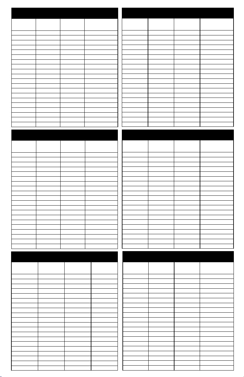
PSE FEVER™: PERFORMANCE DRAW SETTINGS
PSE FEVER 60# PERFORMANCE
CABLE SETTINGS-LONG POST
Inner Cam
Stop
Setting
A-L 29” 60 40
B-L 28¾” 60 40
C-L 27½” 60 40
D-L 27” 60 40
E-L 25¾” 60 40
F-L 25¼” 60 40
G-L 24¼” 60 40
H-L 24” 60 40
I-L 22½” 60 40
J-L 21¾” 60 40
A-S 21¼” 60 40
B-S 20” 60 40
C-S 19¼” 60 40
D-S 18½” 60 40
E-S 18” 60 40
F-S 17¾” 60 40
G-S 17½” 60 40
H-S 17¼” 60 40
I-S 17¼” 60 40
J-S 17” 60 40
PAGE
32
Draw
Length
Setting
Draw
Weight
at
Bottom
Draw
Weight
12 Turns
Off
PSE FEVER 60# PERFORMANCE
CABLE SETTINGS-SHORT POST
Inner Cam
Stop
Setting
A-L 28” 52 36
B-L 27½” 52 36
C-L 26½” 52 36
D-L 26” 52 36
E-L 24¾” 52 36
F-L 24½” 52 36
G-L 23” 52 36
H-L 22½” 52 35
I-L 21¼” 48 33
J-L 20¼” 48 31
A-S 19¾” 47 31
B-S 18½” 47 31
C-S 18” 47 31
D-S 17” 47 31
E-S 16½” 47 31
F-S 16¼” 47 31
G-S 16” 47 31
H-S 16” 47 31
I-S 15¾” 47 31
J-S 15½” 47 31
Draw
Length
Setting
Draw
Weight
at
Bottom
Draw
Weight
12 Turns
Off
Page 32

PSE FEVER 50# PERFORMANCE
Inner Cam
CABLE SETTINGS-LONG POST
Stop
Setting
A-L 29” 50 33
B-L 28¾” 50 33
C-L 27½” 50 33
D-L 27” 50 33
E-L 25¾” 50 33
F-L 25¼” 50 33
G-L 24¼” 50 33
H-L 24” 50 33
I-L 22½” 50 33
J-L 21¾” 50 33
A-S 21¼” 50 33
B-S 20” 50 33
C-S 19¼” 50 33
D-S 18½” 50 33
E-S 18” 50 33
F-S 17¾” 50 33
G-S 17½” 50 33
H-S 17¼” 50 33
I-S 17¼” 50 33
J-S 17” 50 33
Draw
Length
Setting
Draw Weight
at
Bottom
PSE FEVER 40# PERFORMANCE
Inner Cam
CABLE SETTINGS-LONG POST
Stop
Setting
A-L 29” 40 26
B-L 28¾” 40 26
C-L 27½” 40 26
D-L 27” 40 26
E-L 25¾” 40 26
F-L 25¼” 40 26
G-L 24¼” 40 26
H-L 24” 40 26
I-L 22½” 40 26
J-L 21¾” 40 26
A-S 21¼” 40 26
B-S 20” 40 26
C-S 19¼” 40 26
D-S 18½” 40 26
E-S 18” 40 26
F-S 17¾” 40 26
G-S 17½” 40 26
H-S 17¼” 40 26
I-S 17¼” 40 26
J-S 17” 40 26
Draw
Length
Setting
Draw Weight
at
Bottom
PSE FEVER 29# PERFORMANCE
Inner Cam
CABLE SETTINGS-LONG POST
Stop
Setting
A-L 29” 29 19
B-L 28¾” 29 19
C-L 27½” 29 19
D-L 27” 29 19
E-L 25¾” 29 19
F-L 25¼” 29 19
G-L 24¼” 29 19
H-L 24” 29 19
I-L 22½” 29 19
J-L 21¾” 29 19
A-S 21¼” 29 19
B-S 20” 29 19
C-S 19¼” 29 19
D-S 18½” 29 19
E-S 18” 29 19
F-S 17¾” 29 19
G-S 17½” 29 19
H-S 17¼” 29 19
I-S 17¼” 29 19
J-S 17” 29 19
Draw
Length
Setting
Draw Weight
at
Bottom
Draw
Weight
12 Turns Off
Draw
Weight
12 Turns Off
Draw
Weight
12 Turns Off
PSE FEVER 50# PERFORMANCE
CABLE SETTINGS-SHORT POST
Inner Cam
Stop
Setting
A-L 28” 43 30
B-L 27½” 43 30
C-L 26½” 43 30
D-L 26” 43 30
E-L 24¾” 43 30
F-L 24½” 43 30
G-L 23” 43 30
H-L 22½” 43 29
I-L 21¼” 40 27
J-L 20¼” 40 26
A-S 19¾” 39 26
B-S 18½” 39 26
C-S 18” 39 26
D-S 17” 39 26
E-S 16½” 39 26
F-S 16¼” 39 26
G-S 16” 39 26
H-S 16” 39 26
I-S 15¾” 39 26
J-S 15½” 39 26
Draw
Length
Setting
DrawWeight
at
Bottom
PSE FEVER 40# PERFORMANCE
CABLE SETTINGS-SHORT POST
Inner Cam
Stop
Setting
A-L 28” 35 24
B-L 27½” 35 24
C-L 26½” 35 24
D-L 26” 35 24
E-L 24¾” 35 24
F-L 24½” 35 24
G-L 23” 35 24
H-L 22½” 35 23
I-L 21¼” 32 22
J-L 20¼” 32 21
A-S 19¾” 31 21
B-S 18½” 31 21
C-S 18” 31 21
D-S 17” 31 21
E-S 16½” 31 21
F-S 16¼” 31 21
G-S 16” 31 21
H-S 16” 31 21
I-S 15¾” 31 21
J-S 15½” 31 21
Draw
Length
Setting
DrawWeight
at
Bottom
PSE FEVER 29# PERFORMANCE
CABLE SETTINGS-SHORT POST
Inner Cam
Stop
Setting
A-L 28” 25 18
B-L 27½” 25 18
C-L 26½” 25 18
D-L 26” 25 18
E-L 24¾” 25 18
F-L 24½” 25 18
G-L 23” 25 18
H-L 22½” 25 17
I-L 21¼” 23 16
J-L 20¼” 23 15
A-S 19¾” 23 15
B-S 18½” 23 15
C-S 18” 23 15
D-S 17” 23 15
E-S 16½” 23 15
F-S 16¼” 23 15
G-S 16” 23 15
H-S 16” 23 15
I-S 15¾” 23 15
J-S 15½” 23 15
Draw
Length
Setting
Draw Weight
at
Bottom
Draw
Weight
12 Turns Off
Draw
Weight
12 Turns Off
Draw
Weight
12 Turns Off
PAGE
33
Page 33

COMPOUND BOW
USER’S GUIDE
PSE FEVER™: GROW WITH YOU DRAW SETTINGS
PSE FEVER 60# GROW WITH YOU
CABLE SETTINGS-LONG POST
Inner Cam
Stop
Setting
A-L 28¾” 54 37¼
B-L 28½” 54 37¼
C-L 27¼” 54 37¼
D-L 26¾” 54 37¼
E-L 25½” 54 37¼
F-L 25” 54 37¼
G-L 24” 54 37¼
H-L 23¼” 54 37¼
I-L 22” 54 36
J-L 21½” 52¾ 34¾
A-S 21” 51½ 33½
B-S 19½” 49¼ 32½
C-S 18¾” 48 31¼
D-S 17½” 43¼ 28¾
E-S 17” 40¾ 26½
F-S 16” 36 24
G-S 15½” 33½ 21½
H-S 14½” 28¾ 19¼
I-S 14¼” 28¾ 19¼
J-S 13½” 28¾ 19¼
PAGE
34
Draw
Length
Setting
Draw
Weight at
Bottom
Draw
Weight
12 Turns Off
PSE FEVER 60# GROW WITH YOU
CABLE SETTINGS-SHORT POST
Inner Cam
Stop
Setting
A-L 27¾” 49¼ 33½
B-L 27¼” 49¼ 33½
C-L 26” 49¼ 33½
D-L 25½” 49¼ 33½
E-L 24½” 49¼ 33½
F-L 24” 48 32½
G-L 22¾” 46¾ 31¼
H-L 22¼” 45½ 31¼
I-L 21” 43¼ 28¾
J-L 20” 42 28¾
A-S 19½” 40¾ 31¼
B-S 18” 37¼ 25¼
C-S 17½” 34¾ 22¾
D-S 16” 30 20½
E-S 15¼” 27½ 18
F-S 14” 22¾ 14½
G-S 13½” 20½ 13¼
H-S 12½” 15½ 10¾
I-S 12” 13¼ 9½
J-S 11” 13¼ 8½
Draw
Length
Setting
Draw
Weight at
Bottom
Draw
Weight
12 Turns Off
Page 34

PSE FEVER 50# GROW WITH YOU
CABLE SETTINGS-LONG POST
Inner Cam
Stop
Setting
A-L 28¾” 45 31
B-L 28½” 45 31
C-L 27¼” 45 31
D-L 26¾” 45 31
E-L 25½” 45 31
F-L 25” 45 31
G-L 24” 45 31
H-L 23¼” 45 31
I-L 22” 45 30
J-L 21½” 44 29
A-S 21” 43 28
B-S 19½” 41 27
C-S 18¾” 40 26
D-S 17½” 36 24
E-S 17” 34 22
F-S 16” 30 20
G-S 15½” 28 18
H-S 14½” 24 16
I-S 14¼” 24 16
J-S 13½” 24 16
Draw
Length
Setting
Draw
Weight at
Bottom
Draw
Weight
12 Turns Off
PSE FEVER 50# GROW WITH YOU
CABLE SETTINGS-SHORT POST
Inner Cam
Stop
Setting
A-L 27¾” 41 28
B-L 27¼” 41 28
C-L 26” 41 28
D-L 25½” 41 28
E-L 24½” 41 28
F-L 24” 40 27
G-L 22¾” 39 26
H-L 22¼” 38 26
I-L 21” 36 24
J-L 20” 35 24
A-S 19½” 34 26
B-S 18” 31 21
C-S 17½” 29 19
D-S 16” 25 17
E-S 15¼” 23 15
F-S 14” 19 12
G-S 13½” 17 11
H-S 12½” 13 9
I-S 12” 11 8
J-S 11” 11 7
Draw
Length
Setting
Draw
Weight at
Bottom
Draw
W
eight
12 Turns Off
PSE FEVER 40# GROW WITH YOU
CABLE SETTINGS-LONG POST
Inner Cam
Stop
Setting
A-L 28¾” 36 24¾
B-L 28½” 36 24¾
C-L 27¼” 36 24¾
D-L 26¾” 36 24¾
E-L 25½” 36 24¾
F-L 25” 36 24¾
G-L 24” 36 24¾
H-L 23¼” 36 24¾
I-L 22” 36 24
J-L 21½” 35¼ 23¼
A-S 21” 34½ 22½
B-S 19½” 32¾ 21½
C-S 18¾” 32 20¾
D-S 17½” 28¾ 19¼
E-S 17” 27¼ 17½
F-S 16” 24 16
G-S 15½” 22½ 14½
H-S 14½” 19¼ 12¾
I-S 14¼” 19¼ 12¾
J-S 13½” 19¼ 12¾
Inner Cam
Stop
Setting
A-L 28¾” 26 18
B-L 28½” 26 18
C-L 27¼” 26 18
D-L 26¾” 26 18
E-L 25½” 26 18
F-L 25” 26 18
G-L 24” 26 18
H-L 23¼” 26 18
I-L 22” 26 17½
J-L 21½” 25½ 16¾
A-S 21” 25 16¼
B-S 19½” 23¾ 15¾
C-S 18¾” 23¼ 15
D-S 17½” 21 14
E-S 17” 19¾ 12¾
F-S 16” 17½ 11½
G-S 15½” 16¼ 10½
H-S 14½” 14 9¼
I-S 14¼” 14 9¼
J-S 13½” 14 9¼
Draw
Length
Setting
PSE FEVER 29# GROW WITH YOU
CABLE SETTINGS-LONG POST
Draw
Length
Setting
Draw
Weight at
Bottom
Draw
Weight at
Bottom
Draw
Weight
12 Turns Off
Draw
Weight
12 Turns Off
PSE FEVER 40# GROW WITH YOU
CABLE SETTINGS-SHORT POST
Inner Cam
Stop
Setting
A-L 27¾” 32¾ 21½
B-L 27¼” 32¾ 21½
C-L 26” 32¾ 21½
D-L 25½” 32¾ 21½
E-L 24½” 32¾ 21½
F-L 24” 32 21½
G-L 22¾” 31¼ 20¾
H-L 22¼” 30½ 20¾
I-L 21” 28¾ 19¼
J-L 20” 28 19¼
A-S 19½” 27¼ 20¾
B-S 18” 24¾ 16¾
C-S 17½” 23¼ 15¼
D-S 16” 20 13½
E-S 15¼” 18½ 12
F-S 14” 15¼ 9½
G-S 13½” 13½ 8¾
H-S 12½” 10½ 7¼
I-S 12” 8¾ 6½
J-S 11” 8¾ 5½
PSE FEVER 29# GROW WITH YOU
Inner Cam
Stop
Setting
A-L 27¾” 23¾ 16¼
B-L 27¼” 23¾ 16¼
C-L 26” 23¾ 16¼
D-L 25½” 23¾ 16¼
E-L 24½” 23¾ 16¼
F-L 24” 23¼ 15¾
G-L 22¾” 22½ 15
H-L 22¼” 22 15
I-L 21” 21 14
J-L 20” 20¼ 14
A-S 19½” 19¾ 15
B-S 18” 18 12¼
C-S 17½” 16¾ 11
D-S 16” 14½ 9¾
E-S 15¼” 13¼ 8¾
F-S 14” 11 7
G-S 13½” 9¾ 6½
H-S 12½” 7½ 5¼
I-S 12” 6½ 4¾
J-S 11” 6½ 4
Draw
Length
Setting
CABLE SETTINGS-SHORT POST
Draw
Length
Setting
Draw
Weight at
Bottom
Draw
Weight at
Bottom
Draw
Weight
12 Turns Off
Draw
Weight
12 Turns Off
Page 35

COMPOUND BOW
USER’S GUIDE
MINI BURNER™ XT: PERFORMANCE DRAW SETTINGS
PSE MINI BURNER XT- 50# PERFORMANCE
CABLE SETTINGS-LONG POST
Inner Cam
Stop
Setting
A-L 28¼” 50 37
B-L 28” 50 37
C-L 27” 50 37
D-L 26½” 50 35
E-L 25¼” 50 35
F-L 25” 50 35
G-L 23¾” 50 35
H-L 23½” 50 35
I-L 22½” 50 35
J-L 21½” 50 35
A-S 21” 50 34
B-S 20” 50 34
C-S 19¼” 50 34
D-S 18¼” 50 34
E-S 18” 50 34
F-S 17¾” 50 34
G-S 17½” 50 34
H-S 17¼” 50 34
I-S 17” 50 34
J-S 16¾” 50 34
PAGE
36
Draw
Length
Setting
Draw
Weight at
Bottom
Draw
Weight
6 Turns Off
PSE MINI BURNER XT- 50# PERFORMANCE
CABLE SETTINGS-SHORT POST
Inner Cam
Stop
Setting
A-L 27½” 43 33
B-L 27¼” 43 33
C-L 26” 43 33
D-L 25¾” 43 32
E-L 24½” 43 32
F-L 24” 43 32
G-L 22¾” 42 32
H-L 22½” 42 31
I-L 21¼” 40 29
J-L 20¾” 40 29
A-S 20” 40 29
B-S 18¾” 40 29
C-S 18” 40 29
D-S 17¼” 40 29
E-S 16¾” 40 29
F-S 16½” 40 29
G-S 16¼” 40 29
H-S 16” 40 29
I-S 15¾” 40 28
J-S 15½” 40 28
Draw
Length
Setting
Draw
Weight at
Bottom
Draw
Weight
6 Turns Off
Page 36

PSE MINI BURNER XT- 40# PERFORMANCE
Inner Cam
CABLE SETTINGS-LONG POST
Stop
Setting
A-L 28¼” 40 30
B-L 28” 40 30
C-L 27” 40 30
D-L 26½” 40 28
E-L 25¼” 40 28
F-L 25” 40 28
G-L 23¾” 40 28
H-L 23½” 40 28
I-L 22½” 40 28
J-L 21½” 40 28
A-S 21” 40 28
B-S 20” 40 27
C-S 19¼” 40 27
D-S 18¼” 40 27
E-S 18” 40 27
F-S 17¾” 40 27
G-S 17½” 40 27
H-S 17¼” 40 27
I-S 17” 40 27
J-S 16¾” 40 27
PSE MINI BURNER XT- 29# PERFORMANCE
Inner Cam
Stop
Setting
A-L 28¼” 29 21
B-L 28” 29 21
C-L 27” 29 21
D-L 26½” 29 20
E-L 25¼” 29 20
F-L 25” 29 20
G-L 23¾” 29 20
H-L 23½” 29 20
I-L 22½” 29 20
J-L 21½” 29 20
A-S 21” 29 20
B-S 20” 29 20
C-S 19¼” 29 20
D-S 18¼” 29 20
E-S 18” 29 20
F-S 17¾” 29 20
G-S 17½” 29 20
H-S 17¼” 29 20
I-S 17” 29 20
J-S 16¾” 29 20
PSE MINI BURNER XT- 20# PERFORMANCE
Inner Cam
Stop
Setting
A-L 28¼” 20 15
B-L 28” 20 15
C-L 27” 20 15
D-L 26½” 20 14
E-L 25¼” 20 14
F-L 25” 20 14
G-L 23¾” 20 14
H-L 23½” 20 14
I-L 22½” 20 14
J-L 21½” 20 14
A-S 21” 20 14
B-S 20” 20 14
C-S 19¼” 20 14
D-S 18¼” 20 14
E-S 18” 20 14
F-S 17¾” 20 14
G-S 17½” 20 14
H-S 17¼” 20 14
I-S 17” 20 14
J-S 16¾” 20 14
Draw
Length
Setting
CABLE SETTINGS-LONG POST
Draw
Length
Setting
CABLE SETTINGS-LONG POST
Draw
Length
Setting
Draw
Weight at
Bottom
Draw
Weight at
Bottom
Draw
Weight at
Bottom
6 Turns Off
6 Turns Off
6 Turns Off
Draw
Weight
Draw
Weight
Draw
Weight
PSE MINI BURNER XT- 40# PERFORMANCE
CABLE SETTINGS-SHORT POST
Inner Cam
Stop
Setting
A-L 27½” 35 27
B-L 27¼” 35 27
C-L 26” 35 27
D-L 25¾” 35 26
E-L 24½” 35 26
F-L 24” 35 26
G-L 22¾” 34 26
H-L 22½” 34 25
I-L 21¼” 32 23
J-L 20¾” 32 23
A-S 20” 32 23
B-S 18¾” 32 23
C-S 18” 32 23
D-S 17¼” 32 23
E-S 16¾” 32 23
F-S 16½” 32 23
G-S 16¼” 32 23
H-S 16” 32 23
I-S 15¾” 32 23
J-S 15½” 32 23
PSE MINI BURNER XT- 29# PERFORMANCE
Inner Cam
Stop
Setting
A-L 27½” 25 19
B-L 27¼” 25 19
C-L 26” 25 19
D-L 25¾” 25 19
E-L 24½” 25 19
F-L 24” 25 19
G-L 22¾” 24 19
H-L 22½” 24 18
I-L 21¼” 23 17
J-L 20¾” 23 17
A-S 20” 23 17
B-S 18¾” 23 17
C-S 18” 23 17
D-S 17¼” 23 17
E-S 16¾” 23 17
F-S 16½” 23 17
G-S 16¼” 23 17
H-S 16” 23 17
I-S 15¾” 23 16
J-S 15½” 23 16
PSE MINI BURNER XT- 20# PERFORMANCE
Inner Cam
Stop
Setting
A-L 27½” 17 13
B-L 27¼” 17 13
C-L 26” 17 13
D-L 25¾” 17 13
E-L 24½” 17 13
F-L 24” 17 13
G-L 22¾” 17 13
H-L 22½” 17 13
I-L 21¼” 16 12
J-L 20¾” 16 12
A-S 20” 16 12
B-S 18¾” 16 12
C-S 18” 16 12
D-S 17¼” 16 12
E-S 16¾” 16 12
F-S 16½” 16 12
G-S 16¼” 16 12
H-S 16” 16 12
I-S 15¾” 16 11
J-S 15½” 16 11
Draw
Length
Setting
CABLE SETTINGS-SHORT POST
Draw
Length
Setting
CABLE SETTINGS-SHORT POST
Draw
Length
Setting
Draw
Weight at
Bottom
Draw
Weight at
Bottom
Draw
Weight at
Bottom
Draw
Weight
6 Turns Off
W
6 Turns Off
W
6 Turns Off
Draw
eight
Draw
eight
Page 37

COMPOUND BOW
USER’S GUIDE
MINI BURNER™ XT: GROW WITH YOU DRAW SETTINGS
PSE MINI BURNER XT- 50# GROW WITH YOU
CABLE SETTINGS-LONG POST
Inner Cam
Stop
Setting
A-L 28” 45 33
B-L 27¾” 45 33
C-L 26¾” 45 33
D-L 26¼” 45 32
E-L 25” 45 32
F-L 24¾” 45 32
G-L 23½” 45 32
H-L 23¼” 45 32
I-L 22” 45 32
J-L 21” 45 32
A-S 20¾” 44 31
B-S 19½” 40 30
C-S 19” 40 30
D-S 17¾” 37 27
E-S 17¼” 36 25
F-S 16” 30 23
G-S 15¾” 29 22
H-S 15” 26 20
I-S 14¾” 25 19
J-S 14” 25 19
PAGE
38
Draw
Length
Setting
Draw
Weight at
Bottom
Draw
Weight
6 Turns Off
PSE MINI BURNER XT- 50# GROW WITH YOU
CABLE SETTINGS-SHORT POST
Inner Cam
Stop
Setting
A-L 27¼” 40 30
B-L 27” 40 30
C-L 25¾” 40 30
D-L 25½” 39 30
E-L 24” 39 29
F-L 23¾” 39 29
G-L 22½” 38 29
H-L 22½” 38 28
I-L 21” 36 27
J-L 20½” 36 26
A-S 19¾” 34 26
B-S 18½” 32 24
C-S 17¾” 29 22
D-S 16½” 27 19
E-S 15½” 25 17
F-S 14¾” 21 15
G-S 14” 19 11
H-S 13” 16 11
I-S 12¾” 14 10
J-S 11½” 14 9
Draw
Length
Setting
Draw
Weight at
Bottom
Draw
Weight
6 Turns Off
Page 38
PSE MINI BURNER XT- 40# GROW WITH YOU
CABLE SETTINGS-LONG POST
Inner Cam
Stop
Setting
A-L 28” 36 26½
B-L 27¾” 36 26½
C-L 26¾” 36 26½
D-L 26¼” 36 25½
E-L 25” 36 25½
F-L 24¾” 36 25½
G-L 23½” 36 25½
H-L 23¼” 36 25½
I-L 22” 36 25½
J-L 21” 36 25½
A-S 20¾” 35¼ 24¾
B-S 19½” 32 24
C-S 19” 32 24
D-S 17¾” 29½ 21½
E-S 17¼” 28¾ 20
F-S 16” 24 18½
G-S 15¾” 23¼ 17½
H-S 15” 20¾ 16
I-S 14¾” 20 15¼
J-S 14” 20 15¼
PSE MINI BURNER XT- 29# GROW WITH YOU
Inner Cam
Stop
Setting
A-L 28” 26 19¼
B-L 27¾” 26 19¼
C-L 26¾” 26 19¼
D-L 26¼” 26 18½
E-L 25” 26 18½
F-L 24¾” 26 18½
G-L 23½” 26 18½
H-L 23¼” 26 18½
I-L 22” 26 18½
J-L 21” 26 18½
A-S 20¾” 25½ 18
B-S 19½” 23¼ 17½
C-S 19” 23¼ 17½
D-S 17¾” 21½ 15¾
E-S 17¼” 21 14½
F-S 16” 17½ 13¼
G-S 15¾” 16¾ 12¾
H-S 15” 15 11½
I-S 14¾” 14½ 11
J-S 14” 14½ 11
PSE MINI BURNER XT- 20# GROW WITH YOU
Inner Cam
Stop
Setting
A-L 28” 18 13¼
B-L 27¾” 18 13¼
C-L 26¾” 18 13¼
D-L 26¼” 18 12¾
E-L 25” 18 12¾
F-L 24¾” 18 12¾
G-L 23½” 18 12¾
H-L 23¼” 18 12¾
I-L 22” 18 12¾
J-L 21” 18 12¾
A-S 20¾” 17½ 12½
B-S 19½” 16 12
C-S 19” 16 12
D-S 17¾” 14¾ 10¾
E-S 17¼” 14½ 10
F-S 16” 12 9¼
G-S 15¾” 11½ 8¾
H-S 15” 10½ 8
I-S 14¾” 10 7½
J-S 14” 10 7½
Draw
Length
Setting
CABLE SETTINGS-LONG POST
Draw
Length
Setting
CABLE SETTINGS-LONG POST
Draw
Length
Setting
Draw
Weight at
Bottom
Draw
Weight at
Bottom
Draw
Weight at
Bottom
6 Turns Off
6 Turns Off
Draw
Weight
Draw
Weight
Draw
Weight
6 Turns Off
PSE MINI BURNER XT- 40# GROW WITH YOU
Inner Cam
Inner Cam
Inner Cam
CABLE SETTINGS-SHORT POST
Stop
Setting
A-L 27¼” 32 24
B-L 27” 32 24
C-L 25¾” 32 24
D-L 25½” 31¼ 24
E-L 24” 31¼ 23¼
F-L 23¾” 31¼ 23¼
G-L 22½” 30½ 23¼
H-L 22½” 30½ 22½
I-L 21” 28¾ 21½
J-L 20½” 28¾ 20¾
A-S 19¾” 27¼ 20¾
B-S 18½” 25½ 19¼
C-S 17¾” 23¼ 17½
D-S 16½” 21½ 15¼
E-S 15½” 20 13½
F-S 14¾” 16¾ 12
G-S 14” 15¼ 8¾
H-S 13” 12¾ 8¾
I-S 12¾” 11¼ 8
J-S 11½” 11¼ 7¼
PSE MINI BURNER XT- 29# GROW WITH YOU
Stop
Setting
A-L 27¼” 23¼ 17½
B-L 27” 23¼ 17½
C-L 25¾” 23¼ 17½
D-L 25½” 22½ 17½
E-L 24” 22½ 16¾
F-L 23¾” 22½ 16¾
G-L 22½” 22 16¾
H-L 22½” 22 16¼
I-L 21” 21 15¾
J-L 20½” 21 15
A-S 19¾” 19¾ 15
B-S 18½” 18½ 14
C-S 17¾” 16¾ 12¾
D-S 16½” 15¾ 11
E-S 15½” 14½ 9¾
F-S 14¾” 12¼ 8¾
G-S 14” 11 6½
H-S 13” 9¼ 6½
I-S 12¾” 8 5¾
J-S 11½” 8 5¼
PSE MINI BURNER XT- 20# GROW WITH YOU
Stop
Setting
A-L 27¼” 16 12
B-L 27” 16 12
C-L 25¾” 16 12
D-L 25½” 15½ 12
E-L 24” 15½ 11½
F-L 23¾” 15½ 11½
G-L 22½” 15¼ 11½
H-L 22½” 15¼ 11¼
I-L 21” 14½ 10¾
J-L 20½” 14½ 10½
A-S 19¾” 13½ 10½
B-S 18½” 12¾ 9½
C-S 17¾” 11½ 8¾
D-S 16½” 10¾ 7½
E-S 15½” 10 6¾
F-S 14¾” 8½ 6
G-S 14” 7½ 4½
H-S 13” 6½ 4½
I-S 12¾” 5½ 4
J-S 11½” 5½ 3½
Draw
Length
Setting
CABLE SETTINGS-SHORT POST
Draw
Length
Setting
CABLE SETTINGS-SHORT POST
Draw
Length
Setting
Draw
Weight at
Bottom
Draw
Weight at
Bottom
Draw
Weight at
Bottom
Draw
Weight
6 Turns Off
Draw
Weight
6 Turns Off
Draw
Weight
6 Turns Off
Page 39

COMPOUND BOW
USER’S GUIDE
®
LIMITED LIFETIME WARRANTY
Each PSE Bow is backed by a PSE Limited Lifetime Warranty to the
original owner for the life of the product. Product will be replaced
or repaired to restore it to its original performance. Cables, strings,
or wearable items are not covered by this warranty.
Evidence of abuse, mishandling, misuse, or alteration to any
PSE product voids any claim to warranty.
PSE specifications on strings and harnesses must be adhered to.
PSE cannot be held responsible for injury or product failure resulting
from improper use or neglect of maintenance.
All bows must undergo string and cable changes every 5,000 shots
or every 12 months to maintain PSE warranty coverage. Total arrow
weight must be in accordance with the guidelines published by
the Archery Trade Association (ATA) for minimum arrow weight/
bow peak weight. Overstressing PSE compound bows by using
arrows lighter than ATA guideline will void warranty and may cause
damage to the bow or injury to the shooter.
PSE makes no other claims either expressed or implied. In the
interest of product improvement and consumer safety, PSE reserves
the right to make changes in product design, color,
and specifications without notice.
PSE PATENT INFORMATION
Manufactured Under Patents:
5,657,739
5,678,529
5,762,060
5,960,778
6,112,732
6,176,231
6,360,735
6,889,683
6,968,837
7,347,196 B1
RE36,942
7,699,045
7,784,452
7,832,388
7,891,349
7,918,218
7,980,236
7,980,237
Licensed Under Patents:
5,501,208
5,505,185
5,749,351
5,894,835
5,921,227
6,142,132
6,237,584
6,588,411
6,966,314
PAGE
40
Page 40

COMPOUND BOW
USER’S GUIDE
buy pse signature items online!
For PSE shooters, our brand name means more than just a bow; it represents a
lifestyle. PSE customers live our brand 24/7 through shirts, hats, gear, and other
PSE-branded accessories. We’ve dramatically expanded our Signature Series line
with an exciting selection of new products…so don’t wait!
psearcherystore.com
Page 41

COMPOUND BOW
USER’S GUIDE
NOTES:
PAGE
42
Page 42

COMPOUND BOW
USER’S GUIDE
IMPORTANT
WARRANTY REGISTRATION
TO ACTIVATE YOUR BOW WARRANTY, PSE BOW REGISTRATION
MUST BE RECEIVED BY PSE WITHIN 30 DAYS OF PURCHASE.
REGISTER YOUR BOW ONLINE OR COMPLETE THE INFORMATION
AND MAIL-IN THE WARRANTY CARD INSERT.
ONLINE WARRANTY REGISTRATION
Log on at: www.pse-archery.com/registration
The PSE serial number is laser
etched into your riser- opposite
the shelf area.
NOTE: IF THE WARRANTY CARD IS NOT PRESENT, PLEASE USE THE FORM BELOW.
MAIL-IN WARRANTY REGISTRATION
Fill out the form below completely, remove it, place in a stamped envelope and mail to:
PSE WARRANTY REGISTRATION
P.O. Box 5487 Tucson, AZ 85703
SERIAL # OF BOW (SEE ABOVE FOR SERIAL # LOCATION)
BOW MODEL
#
DEALER NAME OR WHERE PURCHASED
YOUR NAME
YOUR ADDRESS
CITY
STATE ZIP
COUNTRY
DATE PURCHASED
APT #
EMAIL ADDRESS
/ / PHONE ( )
PAGE
43
 Loading...