

Page 1
Compound Bow
USER’S GUIDE
Page 2

GENERAL OPERATING INSTRUCTIONS
• Always inspect your bow thoroughly before each shooting session to insure that it is in
good working order. Check for worn or missing components and have them replaced at
an authorized PSE dealer as required, i.e. bushings, spacers, etc.
• Inspect your arrows to insure that they are straight, undamaged and that each nock is in
good condition. A cracked nock can break when fired from the bow and cause the bow
to "dry fire" resulting in possible injury to the archer and damage to the bow.
• When purchasing arrows for your bow, consult the selection chart from the arrow
manufacturer and select the correct arrow for your application. Always use an arrow that
is at least 5 grains per pound of peak bow weight. Failure to do so could cause personal
injury and damage to your bow.
BOW MAINTENANCE
Your PSE bow will give you many years of service if maintained and cared for properly.
IMPORTANT: Before servicing any PSE bow in a bow press, back out each limb bolt 4
complete turns from bottomed position.
• Keep synthetic cables and strings waxed. Apply bow string wax to your synthetic cables
and string before each shooting session.
• Strings and cables must be replaced periodically. A worn cable or string can suddenly
break causing serious injury to the archer and damage to the bow. It is recommended
that the string and cables be replaced at least every 5,000 shots or 12 months.
• Always store your bow in a cool dry place. High temperatures, such as those that can
occur in a truck or interior of a vehicle, can cause serious damage to your bow.
• After use in high humidity or damp conditions, wipe metal components of bow
with a light oil.
SAFETY
As with any weapon, safe operation of your PSE bow must always be the highest priority.
ALWAYS WEAR SAFETY GLASSES WHEN HANDLING A BOW.
Do not attempt to use your bow without proper instruction. Doing so can result in
serious injury.
a. Never "dry-fire" any bow. Dry-firing is drawing and releasing the bowstring without
an arrow on the string. Dry-firing will likely cause damage to the bow and serious
injury to the archer.
b. Always be sure of your intended target as well as what lies behind the target area. An arrow
can travel a considerable distance, so it is important to have a safe and sound backstop.
c. If you draw a bow and need to let it down, do so in a slow and careful manner. Keep
your support arm straight and prepare for a rapid and violent let-down. Avoid hitting
your hand on protruding accessories such as the cable guard or quiver. Keep your head
and face back and out of danger during let-down. Never draw a bow with a peak
weight above your comfort level. Always use a bow sling when drawing a bow.
d. Never modify any part of the bow or its components by drilling extra holes or removing
material. This voids the warranty and presents safety problems.
Thank you from the entire PSE family for purchasing a PSE bow!
Your PSE bow was manufactured from the finest materials available
and handcrafted with pride in the USA. With proper care you will
enjoy the use of this product for years to come.
Please read this entire booklet before shooting or adjusting your bow. Remember,
many adjustments to a compound bow require the use of a bow press. Whenever
shooting a bow, be certain of your target as well as what else lies downrange.
2
Page 3
3
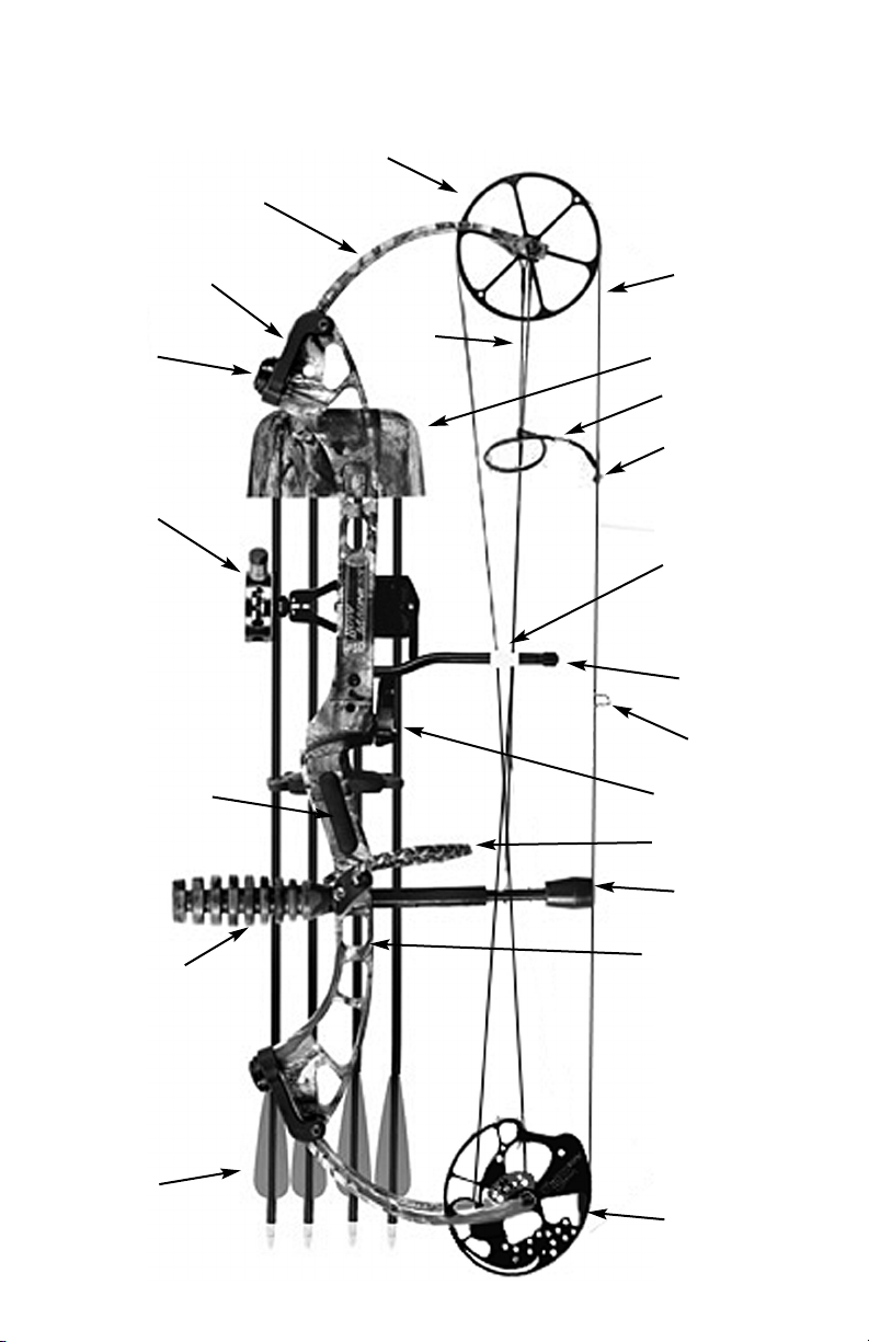
LIMB
LIMB
BOLT
SIGHT
ARROW
REST
GRIP
ARROWS
STABILIZER
IDLER WHEEL
CABLE
QUIVER
PEEP
SIGHT
PEEP
TUBING
STRING
LOOP
CABLE
GUARD
CABLE
GUARD
SLIDE
BOW
SLING
BACKSTOP
RISER
CAM
LIMB
POCKET
STRING
BOW TERMINOLOGY
Page 4
4
Compound Bow
USER’S GUIDE
SETTING-UP YOUR BOW
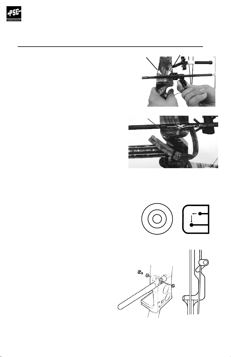
NOCKING POINT PLACEMENT:
Finger shooters: Install the nocking point so that the
arrow passes at the center of the arrowrest mounting hole
and runs slightly point-down relative to the tuning mark
on the window of the bow.
Release Aid shooters: Install the nocking point so that
the arrow passes at the center of the arrowrest mounting
hole and runs parallel to the tuning mark on the window
of the bow.
ARROWREST ADJUSTMENT:
When shooting with a release aid the in/out
position of the arrowrest should be adjusted so that
the arrow runs parallel with the tuning mark on the
shelf when viewed from above. When shooting with
fingers the arrow should point slightly away from
the tuning mark on the shelf.
SIGHT ADJUSTMENT:
When adjusting the sight pin locations, always
remember to "follow the group". That is, if the
shot group is to the left of the target, move the
sight pins to the left. If the shot group is low,
move the sight pins down.
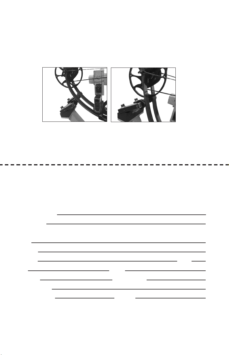
CABLE GUARD ADJUSTMENT &
INSTALLATION:
Install the cable guard as shown in Figure A.
Adjust the cable guard so the cables just clear
the arrow vanes. On bows using an offset
cable guard rod, adjustments must be done
with the rod in the up position (approximately
1 o’clock) as shown in Figure B (11 o’clock for
left handed bows). Excessive arrow clearance
may cause the cable to track incorrectly on the
wheels and cause personal injury and/or
damage to the bow.
Figure A
Figure B
••
•
Alignment
Mark
Alignment
Mark
Arrowrest mounting hole
Page 5
5
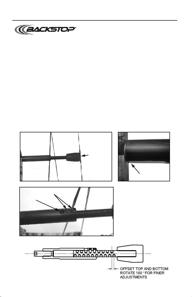
1. Remove the setscrews from the base using a 1/16” hex wrench.
2. Install the Backstop™into the threaded hole below the
grip on the string- facing side of the bow.
3. Extend the Backstop
™
until it makes contact with the string. Mark the string ¼” above
and ¼” below where it makes contact with the string. Remove the Backstop™and
add serving to that area of the string. Reinstall the Backstop™.
4. To avoid any possibility of the cables striking the setscrews, the setscrews must be
facing away from the cables. If they are not, remove the Backstop™base, add the
washer provided and reinstall the Backstop™base as shown.
5. Securely tighten the base to the bow handle.
6. Extend rod from base until rubber stopper contacts the string. Rotate rod until the
indentation in the rod closest to the alignment hole (see picture) can be identified.
Rod should be rotated 180° and the rod/stopper lightly pushed into the string until
the next available indentation is visible (Detent holes are offset – see picture below).
Install the setscrews to secure rod in this position. Tighten setscrews.
BACKSTOP™ INSTRUCTIONS
Serve string
in this area.
Set screws
Alignment
hole
Add washer
if setscrews
are near
cables.
Note: Many PSE bow models come from the factory with the Backstop™installed.
These instructions refer to reinstallation or adjustment if needed after making adjustments
to your PSE bow.
Page 6

6
Compound Bow
USER’S GUIDE
INSTALLATION OF ACCESSORIES
Arrowrest/Overdraw: The arrowrest or overdraw
should be installed according to the instructions received
with the product. It is usually mounted to the riser in the
threaded hole on the side opposite the shelf (hole "A")
using the hardware provided with the arrowrest or
overdraw.
Sight: The sight should be installed according to the
instructions received with the product. It is usually
mounted to the riser in the threaded holes (holes "B") on
the side opposite the shelf using the hardware provided
with the sight. Some bows are equipped with multiple
sight mounting holes which allow the sight to be moved
up or down.
Stabilizer: The stabilizer should be mounted according
to the manufacturer's recommendation. It is usually
mounted in the threaded hole on the front of the riser
(hole "C").
Bow Sling: The bow sling attaches to the riser of the
bow generally with the stabilizer. If a stabilizer is not
used, attach the sling to the riser with the correct sized
bolt using the hole provided for the stabilizer (hole "C").
OTHER ADJUSTMENTS
Draw Weight: Your bow is factory-set to within 2 lbs. of
the peak draw weight indicated on the label on the
lower limb of the bow. Changes in draw weight can be
made by turning the limb bolt in or out. Before making
any changes in weight, turn the limb bolt clockwise to
the bottom position. Never use extreme torque when
turning the bolt or damage to the limb may occur. The
limb bolt then may be turned counterclockwise to obtain
the desired weight, but NEVER more than 4 turns or
revolutions. Adjust each limb exactly the same.
CAUTION: On some bow models, the limb bolt locking
screw MUST be loosened BEFORE adjusting.
Wheels/Cams: Many PSE wheels and cams have
adjustable features. Each one comes from the factory
set-up and ready to use but there may be occasions
where you need to adjust the characteristics of your bow.
In some cases you will need a PSE Tune Chart to
determine what to adjust, and you may need to see a
PSE Dealer for information. If you are not sure of the adjustment you are making, stop and see
your PSE Dealer for assistance. In most cases, an appropriate bow press will be needed to make
adjustments to cams and wheels. If you do not have an appropriate press, see your PSE Dealer.
Hole
A
Holes
B
Hole
C
Your Authorized PSE Dealer is supplied with technical information on PSE bows and cams.
Please see your Dealer for assistance when making these adjustments.
Page 7

7
CAM ADJUSTMENTS
CAM ORIENTATION:
On cams with orientation marks, a reference mark is found to indicate an approximate
orientation. This line is for reference only and is meant to give approximate orientation only
and may vary between bow models. The orientation of the cams may be changed slightly by
twisting or untwisting the string or cable. If attaching the string to the “+” or the “-“ post,
the orientation marks will not be aligned with the cable.
DRAW LENGTH:
ALL MODULAR CAMS (EXCEPT SU CAM)
To change the draw length in 1” increments, the module must be changed. See your local
PSE dealer for information on how to obtain a replacement module. NOTE: some modules
can be changed without a bowpress. Top and bottom modules must be the same size
designation (the physical size may vary) and draw stop position must correspond.
For minor changes in draw length, the bow must be placed in a suitable bow press and
tension relieved from the string and cable. The string side of the cam may have additional
posts. Moving the string from the post with the dot to the post with the “+” will increase
draw by approximately ¼”. Moving the string from the post with the dot to the post with
the “-“ will decrease draw by approximately ¼”.
ALL INNER CAMS:
This system allows draw length adjustments over a prescribed range without putting the
bow in a bowpress. In all cases, the "A" setting is the longest draw length for that bow
and draw lengths get shorter as you progress up the alphabet (A to B, B to C, etc.) When
adjusting the inner cam on a two-cam bow or hybrid cam bow, both cams must be set in
the same letter position. In cases where there is a separate draw stop, the draw stop must
be moved to the hole marked with the corresponding letter as the inner cam setting.
STOP ADJUSTMENTS:
DRAW STOP:
The position of the draw stop must match the size of the module. For example, if the cam
is equipped with a number 7 module the draw stop must be placed in one of the draw stop
holes marked with a “7”. If the inner cam is in the “B” stop, the stop must be in “B”.
LET-OFF:
Let-off adjustment is part of the draw stop. To adjust from higher to lower let-off, remove
the draw stop from the higher let-off hole and reinstall it in the lower let-off hole
of the corresponding module number. For example, if the cam is equipped with a
number 7 module the stop must be reinstalled in the hole marked “7” in the row
marked with the lower let-off setting. Changing to lower let-off will shorten the draw
length a small amount.
STAGE 3™:
DRAW LENGTH: The draw length is adjusted by placing the bow in an appropriate bow
press and relieving the tension from the string and cables. Move the string to the slot that
will shorten the effective length of the string to shorten the draw length by ½” per wheel.
Move the string to the slot that will lengthen the effective length of the string to lengthen
the draw of the bow by ½” per wheel.
Page 8

8
Compound Bow
USER’S GUIDE
SYNERGY UNIVERSAL 2-CAM SYSTEM
The Synergy Universal Cam is the most advanced entry-level two-cam system available.
Both draw weight and draw length adjustments are incorporated into the design and can be
changed without the use of a bow press.
The system comes with three pairs of modules (8912, 8913 and 8914) that allow 6 different
draw length settings and 3 different weight settings. Each system will function on both
right-handed and left-handed bows. The illustration below will show a right-handed
installation. Left-handed will be mirror image of all diagrams.
Each cam is marked “RHT/LHB” (Right-Hand Top or Left-Hand Bottom) or “RHB/LHT”
(Right-Hand Bottom or Left-Hand Top) for easy identification.
1. Draw Length: The #6 is used for the shortest draw (25” to 26” range on most bows).
Increasing the module number increases the draw length usually by about 1” per number.
Note that each module can be flipped over and used as a different number. Place module
on the cam but do not install the screws at this point.
2. Weight setting: With the module in the proper position on the cam, move the module
until the hole marked “L”, “M” or “H” in the module is aligned with the threaded hole in the
cam, as shown below. Secure the module to the cam in two places with the washers and
screws provided. Repeat this operation for the cam on the other end of the bow. Moving the
module from “M” to “L” decreases the weight by about 5 pounds and moving the module
from “M” to “H” increases the draw weight be about 5 pounds. Weight adjustments can also
be made by turning the limb bolts either in or out. NEVER TURN THE LIMB BOLT OUT MORE
THAN 4 TURNS.
3. NOTES: When changing weight using module adjustments, the following can be
expected: from Light “L” to Medium “M”, draw length increased by ¼”. From Medium “M” to
Heavy “H”, draw length increases ¼”. Be aware that let-off varies with draw length changes.
Some variations in let-off, length of “valley” and firmness of “wall” may occur when
changing module settings.
Module Number Size (normal) Size (flipped over)
8912 #11 #6
8913 #10 #7
8914 #9 #8
Page 9

9
DRAW WEIGHT ADJUSTMENTS
ASYMMETRIC IDLER
PSE has two types of pocket systems: hard stop pockets and vibration damper pockets.
Hard stop limb pockets have a “bottomed” position to determine peak weight.
This position is where the limb, pocket and riser contact
one another and cannot be adjusted further.
Vibration damper pockets have rubber in between the limb
and pocket and the riser. The “bottomed” limb position is
NOT when the limbs contact the riser. The bottomed
position for vibration damper pockets is where the bottom
surface of the limb is approximately .20” (3/16” or 5 mm)
away from the riser. The limb bolt may be adjusted to
slightly increase the draw weight, but the gap between the
limb and riser must never be less than 0.15” (4 mm).
IMPORTANT: Do not “bottom” the limbs
against the riser on a bow equipped with
vibration damper pockets!
Some PSE bows are equipped with a
special asymmetric idler wheel, which is
assembled on the top limb. It is essential
that the idler be oriented properly.
The wide edge of the idler always goes
to the cable guard side of the bow. The
illustration shows the proper orientation
of the idler for a right-handed bow
when viewed while holding the bow
as it is shot.
VIBRACHECKTMHUSH KIT ACCESSORIES
Wide edge
Limb Band
Cable Guard Damper
Example of vibration damper pocket.
Under-limb pad removed for clarity.
If your bow is equipped with limb bands,
the proper placement of the bands is
approximately 1/8” beyond the limb fork.
If your bow is equipped with a Cable Guard
Damper it should be even with the cable slide
when the bow is at rest. More than one
Cable Guard Damper can be used.
Page 10

Compound Bow
USER’S GUIDE
10
X TECHNOLOGY
The X Technology bows come with many unique features that will
enhance your archery experience.
INDEPENDENT SPLIT LIMB POCKET SYSTEM
Some X Technology bows are equipped with independent split limb (ISL)
pockets. If servicing a bow with ISL pockets refer to the instruction sheet
that came with the bow or visit www.pse-archery.com.
Do not make any adjustment to this system without
referring to the instructions.
MAINTENANCE
Your bow is a mechanical device that is subject to wear and therefore
must be inspected periodically and given the proper adjustments and service. It is
recommended that this service be performed at least once a year by an authorized PSE
dealer. All components, including string, cables, axles, e-clips, limbs and riser should be
carefully inspected for damage or wear.
STRINGS AND CABLES
Apply a light coat of high quality bowstring wax to your string and cable each time you shoot
your bow. It is especially important NOT to wax the area of the string that wraps around the
idler wheel. This area of the string should be treated with a cam lubricant. This will help
reduce wear on your string and cables. Inspect the string and cables regularly and replace
them when there is evidence of wear, every 5000 shots or every 12 months.
USING A BOW PRESS
ALL X Technology bows MUST be serviced in an approved bow press and require special
consideration. Do not attempt to service these bows in any bow press without reviewing the
procedures described herein.
Use of a non-approved bow press or improper use of an approved bow press WILL result in
damage to the bow and possible personal injury. Damages incurred by improper use or
maintenance will not be covered under the warranty. See the PSE website for a list of
approved bow presses www.pse-archery.com
There are two basic types of approved presses available: compression-type and pull-type.
COMPRESSION-TYPE BOW PRESS:
This type of press pushes in a horizontal direction against the tips of the limbs.
No other support for the bow is required.
When using a press of this type, back each limb bolt out 4 turns from the bottom setting,
position the bow in the press and crank press inward to apply a compression force against
the limb tips as shown.
ISL Pocket
COMPRESSION FORCE
Page 11

11
Compress ONLY far enough to loosen
the string and cables. Over compressing
could break the limbs and cause
personal injury. Any damages incurred
from over-compressing will not be
covered under warranty.
PULL-TYPE PRESS:
This type of press pulls the riser of the bow in
a vertical direction between rollers that
compress the limbs.
When using this type press it is very
important to position the rollers and pressure points correctly.
Back the limb bolts out 4 turns from the bottom setting
and position the pressure points on the riser as close to
the limbs as possible WITHOUT making contact with the
limbs as shown in the photo. The pressure points must
not contact the limbs at any time during servicing.
(Continued on page 12)
Page 12
Position the limb rollers outward on the limbs so that when the riser is pulled down the bow
does not slip through/between the rollers before releasing tension on the string and cables. The
rollers must be at least 4” from the limb pockets or the limbs will break. While placing tension
on the limbs, BE VERY CAREFUL NOT TO PULL THE RISER DOWN TOO FAR. DEFLECT THE
LIMBS JUST ENOUGH TO REMOVE THE STRING AND CABLES.
Never allow the rollers to go past the belly (thinnest part) of the limb.
Service such as peep and vibration damper installation and string replacement can be
performed with a Pocket Press portable bow press (item #01169) available from your
local PSE dealer. Item #01170 and #01031 are pocket presses also available for
alternate axle-to-axle lengths.
IMPORTANT
WARRANTY REGISTRATION
THIS FORM MUST BE RECEIVED BY PSE WITHIN 30 DAYS OF PURCHASE TO ACTIVATE WARRANTY
SERIAL # OF BOW
BOW MODEL
NAME
ADDRESS
ADDRESS APT
CITY STATE
COUNTRY POSTAL CODE
EMAIL ADDRESS
DATE PURCHASED / / PHONE ( )
REGISTRATION
Fill out this form completely, remove it, and mail to:
PSE WARRANTY REGISTRATION
12
You can also register online at www.pse-archery.com/registration
P.O. Box 5487
Tucson, AZ 85703
Page 13

13
BOAR’N THE U.S.A.
From Florida to California
PSE is hunt’n the Wild Boar.
– DVD
HOLDING STEADY
Learn to really aim your
bow. – DVD
BOWHUNTING
DANGEROUS GAME
Bowhunting around the
world! Polar bear, lion,
elephant, crocodile,
leopard, brown bear
and more. – DVD
In the event the DVD or the hat you
are ordering is no longer available
the product will be substituted with
a like item.
Offer good in the United States Only
THANK YOU FOR
SELECTING PSE
ACT NOW ON THIS
ONE-TIME OFFER:
Buy any TWO of these
exciting PSE DVDs and
receive a FREE cap!
CAP STYLE SHOWN MAY VARY
$
18
99
$
18
99
®
Page 14

Name
Address
City State Postal Code (Zip)
Daytime Phone ( )
CREDIT CARD NUMBER
AMEX MC DISC VISA Exp
OR INCLUDE CHECK OR MONEY ORDER
BOAR’N THE U.S.A. FREE CAP
DVD 41295 45354
DANGEROUS GAME HOLDING STEADY
DVD 41349 DVD 41302
SIGNATURE
Mail to: PSE P.O. Box 5487 Tucson, AZ 85703
18.99
3.95
22.94
1.32
24.26
$
$
$
$
$
Shipping & Handling
Total (non-AZ residents)
AZ residents add
Total (AZ residents)
YES, SEND ME TWO DVD VIDEOS AND MY FREE CAP!
Please select two videos from below:
Sorry, available to US residents only.
In the event the DVD or the hat you are ordering is no
longer available the product will be substituted with
a like item.
Offer good in the United States Only
Page 15

NOTES
LIMITED LIFETIME WARRANTY
ALL PSE MANUFACTURED BOWS / ACCESSORIES / KING PRODUCTS
Each PSE Bow is backed by a PSE Limited Lifetime Warranty to the original owner for the life of the product.
Product will be replaced or repaired to restore it to its original performance. Cables, strings, or wearable
items are not covered by this warranty.
Evidence of abuse, mishandling, misuse, or alteration to any PSE product voids any claim to warranty.
PSE specifications on strings and harnesses must be adhered to.
PSE cannot be held responsible for injury or product failure resulting from improper use or neglect of
maintenance.
All bows must undergo string and cable changes every 5,000 shots or every 12 months to maintain PSE
warranty coverage. Total arrow weight must be in accordance with the recommendations made by the Archery
Trade Association (ATA) for minimum arrow weight/bow peak weight. Overstressing PSE compound bows by
using arrows lighter than ATA recommendation will void warranty and may cause damage to the bow or injury
to the shooter.
PSE makes no other claims either expressed or implied. In the interest of product improvement and consumer
safety, PSE reserves the right to make changes in product design, color, and specifications without notice.
REMOVING THE DATA LABEL FROM THE BOTTOM LIMB OF THE BOW MAY VOID THE WARRANTY.
PATENT INFORMATION
One or more of the following patents may apply:
MANUFACTURED UNDER ONE OR MORE OF THE FOLLOWING PATENTS:
4,909,231 4,967,721 5,005,554 5,020,507 5,040,520 5,054,462 5,123,396 5,241,945 5,243,958
5,280,779 5,301,651 5,307,787 5,335,644 5,339,790 5,365,650 5,377,658 5,469,834 5,487,373
5,495,843 5,507,270 5,657,739 5,678,529 5,762,060 5,960,778 6,112,732 6,176,231 6,360,735
6,792,930 6,889,683 6,968,837 RE36,942 D429,309 D503,958 D528,625 7,347,196
LICENSED UNDER:
5,141,689 5,368,006 5,392,756 5,505,185 5,782,229 5,894,835 6,237,584 6,588,411 6,966,314
5,501,208
15
Page 16

16
 Loading...